WO2023243331A1 - フォロア軸受モジュール - Google Patents
フォロア軸受モジュール Download PDFInfo
- Publication number
- WO2023243331A1 WO2023243331A1 PCT/JP2023/019181 JP2023019181W WO2023243331A1 WO 2023243331 A1 WO2023243331 A1 WO 2023243331A1 JP 2023019181 W JP2023019181 W JP 2023019181W WO 2023243331 A1 WO2023243331 A1 WO 2023243331A1
- Authority
- WO
- WIPO (PCT)
- Prior art keywords
- follower bearing
- plate
- hole
- attachment
- bearing module
- Prior art date
- Legal status (The legal status is an assumption and is not a legal conclusion. Google has not performed a legal analysis and makes no representation as to the accuracy of the status listed.)
- Ceased
Links
Images







Classifications
-
- F—MECHANICAL ENGINEERING; LIGHTING; HEATING; WEAPONS; BLASTING
- F16—ENGINEERING ELEMENTS AND UNITS; GENERAL MEASURES FOR PRODUCING AND MAINTAINING EFFECTIVE FUNCTIONING OF MACHINES OR INSTALLATIONS; THERMAL INSULATION IN GENERAL
- F16C—SHAFTS; FLEXIBLE SHAFTS; ELEMENTS OR CRANKSHAFT MECHANISMS; ROTARY BODIES OTHER THAN GEARING ELEMENTS; BEARINGS
- F16C13/00—Rolls, drums, discs, or the like; Bearings or mountings therefor
- F16C13/006—Guiding rollers, wheels or the like, formed by or on the outer element of a single bearing or bearing unit, e.g. two adjacent bearings, whose ratio of length to diameter is generally less than one
-
- F—MECHANICAL ENGINEERING; LIGHTING; HEATING; WEAPONS; BLASTING
- F16—ENGINEERING ELEMENTS AND UNITS; GENERAL MEASURES FOR PRODUCING AND MAINTAINING EFFECTIVE FUNCTIONING OF MACHINES OR INSTALLATIONS; THERMAL INSULATION IN GENERAL
- F16C—SHAFTS; FLEXIBLE SHAFTS; ELEMENTS OR CRANKSHAFT MECHANISMS; ROTARY BODIES OTHER THAN GEARING ELEMENTS; BEARINGS
- F16C19/00—Bearings with rolling contact, for exclusively rotary movement
- F16C19/22—Bearings with rolling contact, for exclusively rotary movement with bearing rollers essentially of the same size in one or more circular rows, e.g. needle bearings
- F16C19/24—Bearings with rolling contact, for exclusively rotary movement with bearing rollers essentially of the same size in one or more circular rows, e.g. needle bearings for radial load mainly
- F16C19/26—Bearings with rolling contact, for exclusively rotary movement with bearing rollers essentially of the same size in one or more circular rows, e.g. needle bearings for radial load mainly with a single row of rollers
-
- F—MECHANICAL ENGINEERING; LIGHTING; HEATING; WEAPONS; BLASTING
- F16—ENGINEERING ELEMENTS AND UNITS; GENERAL MEASURES FOR PRODUCING AND MAINTAINING EFFECTIVE FUNCTIONING OF MACHINES OR INSTALLATIONS; THERMAL INSULATION IN GENERAL
- F16C—SHAFTS; FLEXIBLE SHAFTS; ELEMENTS OR CRANKSHAFT MECHANISMS; ROTARY BODIES OTHER THAN GEARING ELEMENTS; BEARINGS
- F16C19/00—Bearings with rolling contact, for exclusively rotary movement
- F16C19/22—Bearings with rolling contact, for exclusively rotary movement with bearing rollers essentially of the same size in one or more circular rows, e.g. needle bearings
- F16C19/44—Needle bearings
- F16C19/46—Needle bearings with one row or needles
- F16C19/466—Needle bearings with one row or needles comprising needle rollers and an outer ring, i.e. subunit without inner ring
-
- F—MECHANICAL ENGINEERING; LIGHTING; HEATING; WEAPONS; BLASTING
- F16—ENGINEERING ELEMENTS AND UNITS; GENERAL MEASURES FOR PRODUCING AND MAINTAINING EFFECTIVE FUNCTIONING OF MACHINES OR INSTALLATIONS; THERMAL INSULATION IN GENERAL
- F16C—SHAFTS; FLEXIBLE SHAFTS; ELEMENTS OR CRANKSHAFT MECHANISMS; ROTARY BODIES OTHER THAN GEARING ELEMENTS; BEARINGS
- F16C35/00—Rigid support of bearing units; Housings, e.g. caps, covers
- F16C35/04—Rigid support of bearing units; Housings, e.g. caps, covers in the case of ball or roller bearings
- F16C35/06—Mounting or dismounting of ball or roller bearings; Fixing them onto shaft or in housing
- F16C35/063—Fixing them on the shaft
-
- F—MECHANICAL ENGINEERING; LIGHTING; HEATING; WEAPONS; BLASTING
- F16—ENGINEERING ELEMENTS AND UNITS; GENERAL MEASURES FOR PRODUCING AND MAINTAINING EFFECTIVE FUNCTIONING OF MACHINES OR INSTALLATIONS; THERMAL INSULATION IN GENERAL
- F16H—GEARING
- F16H53/00—Cams or cam-followers, e.g. rollers for gearing mechanisms
- F16H53/06—Cam-followers
-
- F—MECHANICAL ENGINEERING; LIGHTING; HEATING; WEAPONS; BLASTING
- F16—ENGINEERING ELEMENTS AND UNITS; GENERAL MEASURES FOR PRODUCING AND MAINTAINING EFFECTIVE FUNCTIONING OF MACHINES OR INSTALLATIONS; THERMAL INSULATION IN GENERAL
- F16C—SHAFTS; FLEXIBLE SHAFTS; ELEMENTS OR CRANKSHAFT MECHANISMS; ROTARY BODIES OTHER THAN GEARING ELEMENTS; BEARINGS
- F16C2204/00—Metallic materials; Alloys
- F16C2204/60—Ferrous alloys, e.g. steel alloys
- F16C2204/62—Low carbon steel, i.e. carbon content below 0.4 wt%
-
- F—MECHANICAL ENGINEERING; LIGHTING; HEATING; WEAPONS; BLASTING
- F16—ENGINEERING ELEMENTS AND UNITS; GENERAL MEASURES FOR PRODUCING AND MAINTAINING EFFECTIVE FUNCTIONING OF MACHINES OR INSTALLATIONS; THERMAL INSULATION IN GENERAL
- F16C—SHAFTS; FLEXIBLE SHAFTS; ELEMENTS OR CRANKSHAFT MECHANISMS; ROTARY BODIES OTHER THAN GEARING ELEMENTS; BEARINGS
- F16C2204/00—Metallic materials; Alloys
- F16C2204/60—Ferrous alloys, e.g. steel alloys
- F16C2204/66—High carbon steel, i.e. carbon content above 0.8 wt%, e.g. through-hardenable steel
-
- F—MECHANICAL ENGINEERING; LIGHTING; HEATING; WEAPONS; BLASTING
- F16—ENGINEERING ELEMENTS AND UNITS; GENERAL MEASURES FOR PRODUCING AND MAINTAINING EFFECTIVE FUNCTIONING OF MACHINES OR INSTALLATIONS; THERMAL INSULATION IN GENERAL
- F16C—SHAFTS; FLEXIBLE SHAFTS; ELEMENTS OR CRANKSHAFT MECHANISMS; ROTARY BODIES OTHER THAN GEARING ELEMENTS; BEARINGS
- F16C2204/00—Metallic materials; Alloys
- F16C2204/60—Ferrous alloys, e.g. steel alloys
- F16C2204/70—Ferrous alloys, e.g. steel alloys with chromium as the next major constituent
-
- F—MECHANICAL ENGINEERING; LIGHTING; HEATING; WEAPONS; BLASTING
- F16—ENGINEERING ELEMENTS AND UNITS; GENERAL MEASURES FOR PRODUCING AND MAINTAINING EFFECTIVE FUNCTIONING OF MACHINES OR INSTALLATIONS; THERMAL INSULATION IN GENERAL
- F16C—SHAFTS; FLEXIBLE SHAFTS; ELEMENTS OR CRANKSHAFT MECHANISMS; ROTARY BODIES OTHER THAN GEARING ELEMENTS; BEARINGS
- F16C2223/00—Surface treatments; Hardening; Coating
- F16C2223/10—Hardening, e.g. carburizing, carbo-nitriding
- F16C2223/12—Hardening, e.g. carburizing, carbo-nitriding with carburizing
-
- F—MECHANICAL ENGINEERING; LIGHTING; HEATING; WEAPONS; BLASTING
- F16—ENGINEERING ELEMENTS AND UNITS; GENERAL MEASURES FOR PRODUCING AND MAINTAINING EFFECTIVE FUNCTIONING OF MACHINES OR INSTALLATIONS; THERMAL INSULATION IN GENERAL
- F16C—SHAFTS; FLEXIBLE SHAFTS; ELEMENTS OR CRANKSHAFT MECHANISMS; ROTARY BODIES OTHER THAN GEARING ELEMENTS; BEARINGS
- F16C2226/00—Joining parts; Fastening; Assembling or mounting parts
- F16C2226/50—Positive connections
- F16C2226/60—Positive connections with threaded parts, e.g. bolt and nut connections
-
- F—MECHANICAL ENGINEERING; LIGHTING; HEATING; WEAPONS; BLASTING
- F16—ENGINEERING ELEMENTS AND UNITS; GENERAL MEASURES FOR PRODUCING AND MAINTAINING EFFECTIVE FUNCTIONING OF MACHINES OR INSTALLATIONS; THERMAL INSULATION IN GENERAL
- F16C—SHAFTS; FLEXIBLE SHAFTS; ELEMENTS OR CRANKSHAFT MECHANISMS; ROTARY BODIES OTHER THAN GEARING ELEMENTS; BEARINGS
- F16C2240/00—Specified values or numerical ranges of parameters; Relations between them
- F16C2240/40—Linear dimensions, e.g. length, radius, thickness, gap
- F16C2240/48—Particle sizes
Definitions
- the present disclosure relates to a follower bearing module.
- This application claims priority based on Japanese Application No. 2022-97876 filed on June 17, 2022, and incorporates all the contents described in the said Japanese application.
- a cam follower mounting structure that is used when attaching a cam follower is known (see, for example, Patent Document 1). Furthermore, a cam follower fixing structure used for fixing the cam follower is known (for example, see Patent Document 2).
- the follower bearing is attached and fixed to the attached member so that the outer ring rotates.
- the installation space at the installation location be as small as possible. That is, it is required to make the installation space of the follower bearing more compact.
- one of the objects is to provide a follower bearing module that can reduce the installation space and improve convenience when installing the follower bearing.
- a follower bearing module is a follower bearing module in which a follower bearing is attached to an attached member provided with an attachment hole.
- the follower bearing module includes a follower bearing, a fixture that attaches the follower bearing to a member to be attached, and a fastener that includes a body portion having a thread on its outer circumferential surface and fastens the follower bearing and the fixture.
- the follower bearing is provided with a shaft through hole that penetrates in the axial direction, and includes an inner member having an annular first raceway surface on the outer peripheral surface, and an annular second raceway surface opposite to the first raceway surface.
- the inner member includes a large diameter portion provided with a first raceway surface, and a shaft portion that extends in the axial direction from the large diameter portion and is at least partially accommodated within the attachment hole.
- the attachment includes a cylindrical part that is placed in the shaft through hole and has a threaded groove on the inner circumferential surface, and a plate part that is provided at one end of the cylindrical part in the axial direction and extends toward the outer diameter side. include.
- the fastener fastens the follower bearing and the mounting tool with the cylindrical portion disposed within the shaft through hole. At least one of the follower bearing and the attachment is provided with a rotation prevention mechanism that prevents rotation of the attachment.
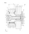
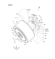
- FIG. 1 is a schematic perspective view of a follower bearing module in Embodiment 1 of the present disclosure.
- FIG. 2 is a schematic cross-sectional view taken along the line II-II in FIG.
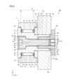
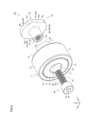
- FIG. 3 is a schematic cross-sectional view taken along the line III--III in FIG. 4 is an exploded perspective view schematically showing the follower bearing module shown in FIG. 1.
- FIG. 5 is a schematic perspective view of a fixture included in the follower bearing module of the first embodiment.
- FIG. 6 is a schematic perspective view of a fixture included in the follower bearing module of the first embodiment.
- FIG. 7 is a schematic rear view of the attachment included in the follower bearing module of the first embodiment.
- FIG. 1 is a schematic perspective view of a follower bearing module in Embodiment 1 of the present disclosure.
- FIG. 2 is a schematic cross-sectional view taken along the line II-II in FIG.
- FIG. 3 is a schematic cross-sectional view taken along the line III--III in
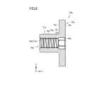
- FIG. 8 is a schematic cross-sectional view of a fixture included in the follower bearing module of the first embodiment.
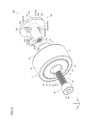
- FIG. 9 is a schematic perspective view of a follower bearing module in Embodiment 2 of the present disclosure.
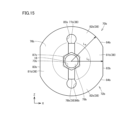
- FIG. 10 is a schematic cross-sectional view taken along the line XX in FIG.
- FIG. 11 is a schematic cross-sectional view taken along the line XI-XI in FIG. 12 is an exploded perspective view schematically showing the follower bearing module shown in FIG. 9.
- FIG. FIG. 13 is a schematic perspective view of a fixture included in the follower bearing module of the second embodiment.
- FIG. 14 is a schematic perspective view of a fixture included in the follower bearing module of the second embodiment.
- FIG. 15 is a schematic rear view of the attachment included in the follower bearing module of the second embodiment.
- a follower bearing module is a follower bearing module in which a follower bearing is attached to a member to be attached that is provided with an attachment hole.
- the follower bearing module includes a follower bearing, a fixture that attaches the follower bearing to a member to be attached, and a fastener that includes a body portion having a thread on its outer circumferential surface and fastens the follower bearing and the fixture.
- the follower bearing is provided with a shaft through hole that penetrates in the axial direction, and includes an inner member having an annular first raceway surface on the outer peripheral surface, and an annular second raceway surface opposite to the first raceway surface.
- the inner member includes a large diameter portion provided with a first raceway surface, and a shaft portion that extends in the axial direction from the large diameter portion and is at least partially accommodated within the attachment hole.
- the attachment includes a cylindrical part that is placed in the shaft through hole and has a threaded groove on the inner circumferential surface, and a plate part that is provided at one end of the cylindrical part in the axial direction and extends toward the outer diameter side. include.
- the fastener fastens the follower bearing and the mounting tool with the cylindrical portion disposed within the shaft through hole. At least one of the follower bearing and the attachment is provided with a rotation prevention mechanism that prevents rotation of the attachment.
- the outer ring is attached to and fixed to an attached member such as a driven member while rotating.
- the follower bearing is attached so that an axially extending portion called a stud is accommodated in an attachment hole provided in the member to be attached. Then, the follower bearing is fixed to the member to be attached so as not to inhibit the rotation of the outer ring.
- it is required to make the installation space more compact and to improve convenience when installing the follower bearing.
- the follower bearing and the attachment are fastened together by the fastener with the shaft portion housed in the attachment hole and the cylindrical portion of the attachment tool disposed within the shaft through hole of the shaft portion.
- Ru The plate-like part of the attachment is relatively thin, and when installing the attachment, the axial length only needs to be in a space equivalent to the thickness of the plate, so the installation space is more compact than when fastening with nuts, etc. be able to.
- the follower bearing module of the present disclosure includes a rotation prevention mechanism that prevents rotation of the attachment tool, when rotating the fastener to fasten the follower bearing and the attachment tool, the follower bearing module of the present disclosure is installed using the rotation prevention mechanism. Rotation of the ingredients can be prevented. Therefore, according to such a follower bearing module, it is possible to make the installation space more compact and to improve the convenience when installing the follower bearing.
- the thickness of the cylindrical portion and the thickness of the plate portion may be equal.
- a fitting having such a configuration can be manufactured, for example, by press molding. Therefore, the fixture can be manufactured efficiently and productivity can be improved.
- the term "thickness is equal" means that the ratio of the thickness of the plate-like part to the thickness of the cylindrical part is 1 or more and 1.3 or less.
- the rotation prevention mechanism includes a notch provided at the axial end of the shaft portion, and a protrusion provided on the outer peripheral surface of the cylindrical portion, protruding toward the outer diameter side and fitting into the notch. , may also be included.
- This type of rotation prevention mechanism prevents the attachment from rotating when the fastener is tightened by the protrusion fitted in the notch catching, thus preventing the so-called co-rotation of the fastener and the attachment. can do. Therefore, the follower bearing can be attached more reliably.
- a plurality of notches and protrusions may be provided at intervals in the circumferential direction of the shaft portion.
- a plate-like part through hole that penetrates the plate-like part may be provided on the outer diameter side of the protrusion.
- the rotation prevention mechanism includes a notch provided at the axial end of the shaft portion, and a protrusion provided on the outer peripheral surface of the cylindrical portion, protruding toward the outer diameter side and fitting into the notch. , a first portion provided on the plate-shaped portion and having a first length in the radial direction and a second portion having a second length longer in the radial direction than the first length;
- the hole portion may be provided to be recessed from one surface of the plate-like portion in the thickness direction and have portions having different diameters.
- a tool can be attached to suppress the rotation of the mounting tool using at least one of the first part, the second part, and the hole, and when tightening with the fastener, Rotation of the fixture can be prevented. Therefore, depending on the situation, it can be attached using any of the anti-rotation mechanisms, and convenience can be further improved.
- the thickness of the cylindrical portion and the thickness of the plate portion may be different.
- a fitting having such a configuration can be manufactured, for example, by forging, specifically cold forging. Therefore, the degree of freedom in design is increased, and the mounting device can be made more responsive to the user's requirements.
- the term "thicknesses are different" means that the ratio of the thickness of the plate-like part to the thickness of the cylindrical part is less than 1 or greater than 1.3.
- the thickness of the plate portion may be thicker than the thickness of the cylindrical portion. By doing so, it is possible to ensure sufficient strength of the plate-shaped portion that mainly contacts the member to be attached. Therefore, the follower bearing can be mounted more firmly.
- an arcuate surface may be formed in a region where the surface of the plate-shaped portion and the outer peripheral surface of the cylindrical portion are continuous in a cross section cut along a plane including the center of the shaft through-hole of the attachment. .
- corners are not included in the area where the surface of the plate-like part and the outer circumferential surface of the cylindrical part are continuous, and it is possible to suppress the occurrence of places where stress is concentrated. Therefore, damage to the mounting tool due to stress concentration can be prevented, and the follower bearing can be mounted more stably.
- the radius of the circular arc surface may be 0.5 mm or more and 1.5 mm or less.
- the radius of the arcuate surface By setting the radius of the arcuate surface to 0.5 mm or more, it is possible to more reliably suppress the occurrence of areas where stress is concentrated.
- the radius of the arcuate surface By setting the radius of the arcuate surface to 1.5 mm or less, it is possible to more reliably reduce the possibility that the inner member included in the follower bearing and the attachment will interfere with each other during attachment. Therefore, by doing so, the follower bearing can be mounted more stably and reliably.
- the anti-rotation mechanism is provided in the plate-shaped portion, and includes a first portion having a first radial length and a second portion having a radial length longer than the first length. and a second portion having a length of .
- a rotation prevention mechanism prevents the rotation of the attachment by attaching a tool that suppresses the rotation of the attachment by using portions of the plate-shaped portion that have different radial lengths when tightening with the fastener. be able to. In this case, since the attachment can be prevented from rotating with the tool from the outer diameter side of the attachment, rotation of the attachment can be more efficiently prevented.
- the outer peripheral surface of the plate-shaped portion corresponding to the first portion may include a flat surface.
- the outer circumferential surface of the plate-shaped portion corresponding to the second portion may include an arcuate surface.
- the outer circumferential surface of the plate-shaped portion corresponding to the first portion may include a plurality of planes arranged parallel to each other at intervals in the circumferential direction.
- the rotation prevention mechanism may include a hole that is recessed from one surface of the plate portion in the thickness direction and that has portions with different diameters.
- Such a rotation prevention mechanism can suppress the rotation of the attachment when the fastener is tightened by fitting a tool that suppresses the rotation of the attachment into the hole. In this case, even if a member that interferes with the tool is arranged on the outer diameter side of the plate-shaped portion, the tool can be fitted into the hole from the axial direction. Therefore, rotation of the attachment can be more efficiently prevented.
- the hole may include a hexagonal hole.
- the plate-shaped portion may be flat.
- the hole portion may be formed in the axial direction of the cylindrical portion so as to extend from the thread groove to one surface of the plate portion. By doing so, it is possible to ensure a wide contact area with the attached member in the flat plate portion. Further, since the hexagonal hole extends from the screw groove to one side surface of the plate-shaped portion, the size of the fixture itself can be made compact, and the installation space can be easily made compact.
- the thickness of the plate portion may be 1 mm or more and 5 mm or less. According to such a fixture, it is possible to ensure the minimum rigidity of the plate-shaped portion and achieve reliable fixation while reducing the installation space. From the viewpoint of further compacting the installation space, it is more preferable that the thickness of the plate-like portion be 1 mm or more and 3 mm or less.
- the follower bearing attachment tool of the present disclosure is included in a follower bearing module that attaches the follower bearing to an attached member provided with an attachment hole, and is a follower bearing attachment tool that attaches the follower bearing to the attached member.
- the follower bearing mount includes a cylindrical part that is placed in the shaft through hole and has a threaded groove on the inner peripheral surface, and a plate part that is provided at one end of the cylindrical part in the axial direction and extends toward the outer diameter side.
- a protrusion provided on the outer circumferential surface of the cylindrical portion and protruding toward the outer diameter side; a first portion provided on the plate portion having a first length in the radial direction; and a first portion having a first length in the radial direction; has a second length that is longer than the first length; and a hole that is recessed from one surface in the thickness direction of the plate-like portion and has portions with different diameters.
- the plate-like part of the mounting tool has a relatively thin wall thickness, and when installing the mounting tool, the axial length only needs to be in a space that is about the same as the thickness of the plate, so it is possible to use nuts, etc.
- the installation space can be made more compact than with fastening.
- the protrusion can be used to prevent the fastener and the attachment from rotating together.
- a tool can be attached to suppress the rotation of the mounting tool using at least one of the first part, the second part, and the hole, and when tightening with the fastener, Rotation of the fixture can be prevented.
- FIG. 1 is a schematic perspective view of a follower bearing module in Embodiment 1 of the present disclosure.
- FIG. 2 is a schematic cross-sectional view taken along the line II-II in FIG.
- FIG. 3 is a schematic cross-sectional view taken along the line III--III in FIG. 4 is an exploded perspective view schematically showing the follower bearing module shown in FIG. 1.
- FIG. 4 illustration of a member to be attached, which will be described later, is omitted.
- the Y direction indicates the axial direction of the follower bearing.
- the X direction and the Z direction indicate the radial direction from the center of the follower bearing when viewed from the axial direction. That is, the X direction and the Z direction are directions when the direction of the rotation center axis of the follower bearing is the Y direction.
- the X direction is a direction perpendicular to the Z direction on a plane perpendicular to the axial direction.
- follower bearing module 10a in the first embodiment includes follower bearing 11, attachment 70a, and bolt 60 as a fastener.
- the follower bearing module 10a is attached to an attached member 90 having a predetermined thickness, such as a driven member.
- the attached member 90 is indicated by a chain line.
- the member to be attached 90 is provided with an attachment hole 93 that penetrates from the first surface 91 to the second surface 92 .
- the follower bearing 11 is attached to the attached member 90 using this attachment hole 93.
- the attachment hole 93 has a round hole shape and passes straight through the follower bearing 11 in the Y direction, which is the axial direction. That is, the inner wall surface 94 forming the attachment hole 93 is a cylindrical surface. Since such a mounting hole 93 can be formed by drilling a so-called straight hole, it can be formed more easily than, for example, a mounting hole provided with a step on the inner wall surface.
- the follower bearing 11 includes a shaft member 12 as an inner member, an outer ring 13, a plurality of rollers 14 as rolling elements, and a cage 15 that holds the rollers 14. Note that in FIGS. 2 and 3, the rotation shaft 16, which is the central axis of the shaft member 12, is illustrated by a dashed line.
- the shaft member 12 includes a rod-shaped main body 17, a flange 18 formed at one end of the main body 17 and having a larger diameter than the main body 17, and a part of the outer peripheral surface of the main body 17 in the circumferential direction. It includes a side plate 19 which is a ring coaxially installed on the main body part 17 so as to surround it.
- the main body portion 17 has a first end surface 21 that is one end in the axial direction, and a second end surface 22 that is the other end opposite to the first end surface 21.
- the first end surface 21 has a circular planar shape.
- the second end surface 22 has a circular planar shape except for a portion where cutouts 34 and 35, which will be described later, are provided.
- An outer circumferential surface 23 of the annular collar portion 18 faces the outer ring 13 .
- a shaft through hole 24 is formed in the shaft member 12 and penetrates in the axial direction from the first end surface 21 to the second end surface 22.
- the opening on the first end surface 21 side and the opening on the second end surface 22 side of the shaft through hole 24 are round holes.
- the inner diameter of the first region 25 located on the first end surface 21 side of the shaft through hole 24 is larger than the inner diameter of the second region 26 adjacent to the first region 25 on the center side in the axial direction.
- the inner diameter of the third region 27 located on the second end surface 22 side of the shaft through hole 24 is larger than the inner diameter of the second region 26 adjacent to the third region 27 on the central side in the axial direction. ing.
- the inner diameter of the first region 25 is larger than the inner diameter of the third region 27.
- the inner diameters of the second region 26 and the third region 27 are larger than the outer diameter of the body portion 61 of the bolt 60, which will be described later.
- a step surface 28 including a plane extending in the radial direction is provided between the first region 25 and the second region 26. This stepped surface 28 comes into contact with a head 62 of a bolt 60, which will be described later, in the axial direction when the follower bearing 11 is attached.
- a step surface 29 including a surface inclined in the axial direction is provided between the third region 27 and the second region 26 .
- the inner circumferential surface of the shaft through hole 24 is not provided with a thread groove, but is configured with a straight surface in the axial direction. Further, the axial length of the third region 27 is longer than the axial length of a cylindrical portion 71a of a fitting 70a, which will be described later.
- the main body portion 17 includes a hollow cylindrical shaft portion 31a, and a large diameter portion 32 that is disposed between a region where the shaft portion 31a and the collar portion 18 are located in the axial direction, and has a larger diameter than the shaft portion 31a. including.
- the outer diameter of the shaft portion 31 a facing the inner wall surface 94 of the attachment hole 93 of the member to be attached 90 is a diameter that is large enough to fit into the attachment hole 93 of the member to be attached 90 . That is, when the follower bearing 11 is attached, the outer peripheral surface 37 of the shaft portion 31a is arranged to face the inner wall surface 94 of the attachment hole 93.
- the outer diameter of the large diameter portion 32 is smaller than the outer diameter of the collar portion 18.
- a first raceway surface 33 having a cylindrical shape is formed on the outer peripheral surface of the large diameter portion 32 . That is, the shaft member 12 has an annular first raceway surface 33 on its outer peripheral surface.
- the main body portion 17 includes a large diameter portion 32 provided with a first raceway surface 33 and a shaft portion 31a that extends in the axial direction from the large diameter portion 32 and is accommodated in the attachment hole 93. include.
- a stepped surface 36 extending in the radial direction is formed on the end surface of the large diameter portion 32 on the shaft portion 31a side in the axial direction.
- the outer peripheral surface 37 of the shaft portion 31a is a cylindrical surface. According to such a configuration, the configuration of the shaft portion 31a can be simplified.
- the annular side plate 19 has a first end surface 41 that is one end surface, a second end surface 42 that is the other end surface, an outer peripheral surface 43, and an inner peripheral surface 44.
- the first end surface 41 and the second end surface 42 are parallel.
- the outer peripheral surface 43 and the inner peripheral surface 44 are concentric cylindrical surfaces.
- the side plate 19 is arranged so that the first end surface 41 contacts the step surface 36 that is the end surface of the large diameter portion 32 on the shaft portion 31a side.
- the inner diameter of the side plate 19 is slightly larger than the outer diameter of the region of the shaft portion 31a that fits into the attachment hole 93.
- a portion having a larger outer diameter than the area that fits into the attachment hole 93 is formed at one end of the shaft portion 31a, and the side plate 19 is press-fitted into the portion of the shaft portion 31a having a larger outer diameter. It is fixed to the large diameter portion 32.
- the shaft member 12 is made of steel such as carbon steel for machine structures, alloy steel for machine structures, and bearing steel.
- a region of the shaft member 12 that includes at least the first raceway surface 33 of the main body portion 17 may be quench-hardened. Further, a part or the whole of the side plate 19 may be quench hardened.
- the outer ring 13 has an annular shape.
- the outer ring 13 has an annular second raceway surface 51 facing the first raceway surface 33 on its inner peripheral surface. Further, the outer ring 13 has an annular outer peripheral surface 52, a first end surface 53, and a second end surface 54.
- the outer circumferential surface 52 is constituted by a cylindrical surface except for the chamfered ends in the axial direction.
- the radial thickness of the central portion 55 of the outer ring 13 provided with the first raceway surface 33 includes the radial thickness of the one end 56 including the first end surface 53 and the second end surface 54. It is thicker than the thickness of the other end portion 57 in the radial direction.
- the inner circumferential surface of the one end portion 56 including the first end surface 53 is recessed toward the outer diameter side so as to receive the flange portion 18 of the shaft member 12 .
- the inner peripheral surface of the other end portion 57 including the second end surface 54 is recessed toward the outer diameter side so as to receive the side plate 19 . That is, the outer ring 13 is configured to be thick at the center portion 55 in the axial direction and thin at both end portions 56 and 57 in the axial direction.
- the outer ring 13 is made of steel.
- steel constituting the outer ring 13 for example, bearing steel, carbon steel for machine structures, alloy steel for machine structures, etc. can be adopted. Further, the outer ring 13 may be quench hardened.
- the cage 15 has an annular shape.
- the cage 15 is made of steel.
- the cage 15 may be made of resin.
- the retainer 15 is arranged in a space sandwiched between the shaft member 12 and the outer ring 13 so as to be concentric with the shaft member 12 and the outer ring 13.
- a plurality of pockets 47 are arranged in the retainer 15 at equal intervals in the circumferential direction.
- One roller 14 is arranged in each of the plurality of pockets 47. By being held by the retainer 15 in this way, the plurality of rollers 14 are arranged on the first raceway surface 33 and the second raceway surface 51 on an annular track along the first raceway surface 33 and the second raceway surface 51. placed in contact with each other.
- the roller 14 has a solid cylindrical shape.
- the roller 14 includes a cylindrical outer peripheral surface 48 and a pair of flat end surfaces 49.
- the end surface 49 of the roller 14 may be spherical.
- the rollers 14 are in contact with the first raceway surface 33 and the second raceway surface 51 at the outer peripheral surface 48 .
- the rollers 14 are made of steel such as bearing steel, for example.
- the rollers 14 may be quench hardened.
- the bolt 60 as a fastener includes a body 61 extending in the axial direction and a head 62 disposed at an end on one side of the body 61 in the axial direction.
- the outer circumferential surface 63 of the body portion 61 is provided with a thread.
- a recess 64 recessed in the axial direction is provided at the end of the head 62 in the axial direction.
- the recess 64 is a hexagonal hole recessed into the shape of a regular hexagonal column, and the bolt 60 can be tightened by inserting a hexagonal wrench into the recess 64.
- FIG. 7 is a schematic rear view of the attachment 70a included in the follower bearing module 10a of the first embodiment.
- FIG. 7 is a diagram of the attachment 70a viewed from the direction opposite to arrow Y.
- FIG. 8 is a schematic cross-sectional view of the attachment 70a.
- FIG. 8 is a cross section taken along a plane that includes the center of the shaft through hole 24 of the fixture 70a. The cross section shown in FIG. 8 is parallel to the YZ plane.
- the attachment 70a includes a cylindrical portion 71a and a plate-shaped portion 72a.
- the cylindrical portion 71a is arranged within the shaft through hole 24.
- a through hole 79a that penetrates in the axial direction is formed in the cylindrical portion 71a.
- the cylindrical portion 71a includes an inner circumferential surface 73a and an outer circumferential surface 74a.
- the outer peripheral surface 74a is a cylindrical surface.
- the outer diameter of the cylindrical portion 71a is smaller than the inner diameter of the shaft through hole 24 in the third region 27. Note that the inner diameter of the second region 26 of the shaft through hole 24 of the main body portion 17 is smaller than the outer diameter of the cylindrical portion 71a.
- a thread groove 77a is provided on the inner circumferential surface 73a of the cylindrical portion 71a.
- the plate-shaped portion 72a is provided at one end of the cylindrical portion 71a in the axial direction.
- the plate-shaped portion 72a has a shape extending toward the outer diameter side.
- the plate-shaped portion 72a has a flat plate shape.
- the plate-shaped portion 72a is not provided with holes or irregularities except for a region in which a hexagonal hole described later is formed.
- the plate-shaped portion 72a includes a surface (first surface) 75a located on one side in the thickness direction (axial direction) and a surface (second surface) 76a located on the other side in the thickness direction.
- the thickness T 1 of the cylindrical portion 71a and the thickness T 2 of the plate portion 72a are different.
- the thickness T 2 of the plate-shaped portion 72a is thicker than the thickness T 1 of the cylindrical portion 71a.
- the thickness T1 of the cylindrical portion 71a is the thickness in the radial direction of the inner circumferential surface 73a and the outer circumferential surface 74a.
- the thickness T1 of the cylindrical portion 71a is the radial length between the radial tip of the thread groove 77a provided on the inner peripheral surface 73a and the outer peripheral surface 74a.
- the thickness T 2 of the plate-like portion 72a is the thickness in the thickness direction (axial direction) of the surface (first surface) 75a and the surface (second surface) 76a.
- the thickness T2 of the plate-like portion 72a is 1 mm or more and 5 mm or less.
- the thickness T2 of the plate-like portion 72a is 2 mm.
- the fitting 70a having such a configuration can be manufactured by forging, specifically cold forging, for example. Therefore, the degree of freedom in design is increased, and the attachment 70a can be made more responsive to the user's requirements.
- the thickness T 2 of the plate-shaped portion 72a is thicker than the thickness T 1 of the cylindrical portion 71a. Therefore, the strength of the plate-shaped portion 72a, which mainly contacts the member to be attached, can be ensured sufficiently. Therefore, the follower bearing 11 can be mounted more firmly. The manufacturing of the fixture 70a will be described in detail later.
- an arcuate surface 78a is formed in a region where the surface (first surface) 75a of the plate-shaped portion 72a and the outer circumferential surface 74a of the cylindrical portion 71a are continuous.
- the radius R1 of the circular arc surface 78a is 0.5 mm or more and 1.5 mm or less. In this embodiment, the radius R1 of the circular arc surface 78a is 0.8 mm.
- the outer shape of the plate-like portion 72a is a circular shape with a portion cut away when viewed from the axial direction (Y direction) which is the thickness direction of the plate-like portion 72a.
- the plate-shaped portion 72a includes a first portion 81a serving as the rotation prevention mechanism 38 whose radial length is a first length L1 , and a second portion 81a whose radial length is longer than the first length. and a second portion 82a as the rotation prevention mechanism 38 having a length L2 (see especially FIG. 7).
- the radial length is the length from the rotating shaft 16 to the outer peripheral surface.
- An outer circumferential surface 83a of the plate-like portion 72a corresponding to the first portion 81a is a flat surface.
- An outer circumferential surface 84a of the plate-like portion 72a corresponding to the second portion 82a is an arcuate surface.
- a plurality of first portions 81a, two in this embodiment, are provided, and the outer peripheral surfaces 83a of the plate-like portion 72a corresponding to the first portions 81a are arranged parallel to each other at intervals in the circumferential direction. .
- Each outer circumferential surface 83a of the first portion 81a and each outer circumferential surface 84a of the second portion 82a are configured to be continuous.
- the outer circumferential surface of the plate-shaped portion 72a is a circular outer circumferential surface when viewed in the axial direction, and is symmetrically arranged at an equal distance from the rotation axis 16 in the X direction on a plane that includes the rotation axis 16 and is parallel to the YZ plane. It has a shape cut in two places.
- a tightening tool such as a spanner with an open end, can be attached to the two first portions 81a so as to sandwich the plate-shaped portion 72a from the outer diameter side as a tool for suppressing the rotation of the attachment tool 70a.
- the plate-shaped portion 72a includes a hole portion 85a serving as the rotation prevention mechanism 38 provided so as to be recessed from one surface in the thickness direction. That is, the hole 85a has a concave shape in the axial direction.
- the hole 85a has portions with different diameters.
- the hole 85a is a hexagonal hole.
- the hole portion 85a is formed in the axial direction of the cylindrical portion 71a from the thread groove 77a to the surface 76a on one side of the plate portion 72a.
- a hexagonal wrench key which serves as a tool for suppressing rotation of the fixture 70a, can be fitted into the hole 85a from the axial direction.
- the shaft portion 31a of the main body portion 17 of the assembled follower bearing 11 is advanced in the direction shown by arrow Y and inserted into the attachment hole 93 of the member to be attached 90.
- the inner wall surface 94 of the attachment hole 93 and the outer peripheral surface 37 of the shaft portion 31a face each other in the radial direction.
- the second end surface 42 of the side plate 19 and the first surface 91 of the attached member 90 come into contact with each other. Note that a gap is formed between the second end surface 54 of the outer ring 13 and the first surface 91 of the attached member 90 in the axial direction.
- the attachment 70a is attached to the attached member 90 from the side opposite to the follower bearing 11, that is, from the second surface 92 side of the attached member 90 in the axial direction.
- the fitting 70a is inserted from the direction opposite to the arrow Y so that the cylindrical portion 71a is fitted into the shaft through hole 24.
- the outer peripheral surface 74a of the cylindrical portion 71a faces the inner peripheral surface in the third region 27 of the shaft through hole 24.
- a bolt 60 as a fastener is inserted into the shaft through hole 24 from the first region 25 side in the direction of arrow Y. Then, rotate and tighten the bolt 60.
- the follower bearing 11 is attached to the member to be attached 90 by tightening the bolt 60 while preventing the rotation of the attachment 70a using the rotation prevention mechanism 38.
- a hexagonal wrench is inserted into the hole 85a and fitted to prevent the attachment tool 70a from rotating.
- a tightening tool such as a wrench with an open end.
- the shaft portion 31a is housed in the mounting hole 93, and the cylindrical portion 71a of the mounting tool 70a is arranged in the shaft through hole 24 of the shaft portion 31a.
- the follower bearing 11 and the fixture 70a are fastened together.
- the plate-shaped portion 72a of the fixture 70a has a relatively thin wall thickness, and when installing the fixture 70a, the axial length only needs to be in a space equivalent to the thickness of the plate, so the installation space is more compact than when fastening with nuts or the like. It is possible to aim for
- the follower bearing module 10a configured as described above includes the rotation prevention mechanism 38 that prevents the rotation of the attachment 70a, when the bolt 60 is rotated to fasten the follower bearing 11 and the attachment 70a, the rotation prevention mechanism 38 can be used to prevent rotation of the fixture 70a. Therefore, according to such a follower bearing module 10a, it is possible to make the installation space more compact and to improve the convenience when installing the follower bearing 11.
- an arcuate surface 78a is formed in a region where the surface 75a of the plate-like portion 72a and the outer circumferential surface 74a of the cylindrical portion 71a are continuous. is formed. Therefore, corners are not included in the region where the surface 75a of the plate-shaped portion 72a and the outer circumferential surface 74a of the cylindrical portion 71a are continuous, and it is possible to suppress the occurrence of stress concentration points. Therefore, damage to the attachment tool 70a due to stress concentration can be prevented, and the follower bearing 11 can be attached more stably.
- the radius R1 of the circular arc surface 78a is 0.5 mm or more and 1.5 mm or less.
- the radius R 1 of the arcuate surface 78a is 0.5 mm or more and 1.5 mm or less.
- the radius R 1 of the arcuate surface 78a By setting the radius R 1 of the arcuate surface 78a to 0.5 mm or more, it is possible to more reliably suppress the occurrence of stress concentration points.
- the radius R 1 of the arcuate surface 78a By setting the radius R 1 of the arcuate surface 78a to 1.5 mm or less, it is possible to more reliably reduce the possibility that the inner member included in the follower bearing 11 and the fitting 70a will interfere with each other during installation. Therefore, by doing so, the follower bearing 11 can be mounted more stably and reliably.
- the rotation prevention mechanism 38 is provided in the plate-like portion 72a, and includes a first portion 81a having a first length in the radial direction and a first portion 81a having a first length in the radial direction. It includes a second portion 82a that is a longer second length.
- a rotation prevention mechanism 38 is a tool that suppresses the rotation of the attachment 70a by using portions of the plate-shaped portion 72a having different radial lengths when the bolt 60 is tightened, such as a tool with an open tip.
- a tightening tool such as a spanner, can be attached to prevent rotation of the fixture 70a. In this case, since the attachment 70a can be prevented from rotating with a tool from the outer diameter side of the attachment 70a, rotation of the attachment 70a can be prevented more efficiently.
- the outer circumferential surface 83a of the plate-like portion 72a corresponding to the first portion 81a includes a flat surface.
- An outer circumferential surface 84a of the plate-like portion 72a corresponding to the second portion 82a includes an arcuate surface. Therefore, the tool for suppressing the rotation of the attachment 70a can be brought into close contact with the outer circumferential surface 83a of the plate-like portion 72a corresponding to the first portion 81a, and rotation of the attachment 70a can be more reliably prevented.
- the outer circumferential surface 83a of the plate-like portion 72a corresponding to the first portion 81a includes a plurality of planes arranged parallel to each other at intervals in the circumferential direction. Therefore, by using the plurality of planes, it is possible to more reliably prevent the attachment 70a from rotating.
- the rotation prevention mechanism 38 is provided to be recessed from one surface of the plate-shaped portion 72a in the thickness direction, and includes a hole portion 85a having portions with different diameters.
- Such a rotation prevention mechanism 38 can suppress the rotation of the attachment 70a when the bolt 60 is tightened by fitting a tool that suppresses the rotation of the attachment 70a into the hole 85a.
- the tool can be fitted into the hole 85a from the axial direction. Therefore, rotation of the attachment 70a can be prevented more efficiently.
- the hole 85a includes a hexagonal hole, when tightening the bolt 60, by fitting a hexagonal wrench into the hole 85a to suppress the rotation of the attachment 70a, the rotation of the attachment 70a can be made more secure. It can be prevented.
- FIG. 9 is a schematic perspective view of a follower bearing module in Embodiment 2 of the present disclosure.
- FIG. 10 is a schematic cross-sectional view taken along the line XX in FIG.
- FIG. 11 is a schematic cross-sectional view taken along the line XI-XI in FIG. 12 is an exploded perspective view schematically showing the follower bearing module shown in FIG. 9.
- FIG. 12 illustration of the attached member is omitted.
- the follower bearing module in Embodiment 2 basically has the same configuration as Embodiment 1, and produces the same effects.
- the follower bearing module of Embodiment 2 differs from Embodiment 1 in that the structure of the shaft included in the main body of the shaft member of the follower bearing and the attachment included in the follower bearing module are different. There is.
- a rotation prevention mechanism is provided at the axial end of the shaft portion 31b included in the main body portion 17 of the shaft member 12 included in the follower bearing module 10b of the second embodiment.
- Notches 34 and 35 as 38 are provided.
- two notches 34 and 35 are provided at intervals of 180 degrees in the circumferential direction.
- the cutouts 34 and 35 are each provided so as to be recessed in a rectangular shape when viewed in the axial direction and the radial direction. That is, the notches 34 and 35 are provided so as to be recessed from the second end surface 22 and the outer circumferential surface 37, respectively.
- the cutouts 34 and 35 have a shape that can fit into a protrusion described later.
- FIG. 15 is a schematic rear view of the attachment 70b included in the follower bearing module 10b of the second embodiment.
- FIG. 15 is a diagram of the attachment 70b viewed from the direction opposite to arrow Y.
- the attachment 70b includes a cylindrical portion 71b and a plate-shaped portion 72b.
- the cylindrical portion 71b is arranged within the shaft through hole 24.
- a through hole 79b that penetrates in the axial direction is formed in the cylindrical portion 71b.
- the cylindrical portion 71b includes an inner circumferential surface 73b and an outer circumferential surface 74b.
- the outer circumferential surface 74b is a cylindrical surface except for a portion where protrusions 77b and 78b, which will be described later, are provided.
- the outer diameter of the cylindrical portion 71b is smaller than the inner diameter of the shaft through hole 24 in the third region 27. Note that the inner diameter of the second region 26 of the shaft through hole 24 of the main body portion 17 is smaller than the outer diameter of the cylindrical portion 71b.
- a thread groove 80b is provided on the inner circumferential surface 73b of the cylindrical portion 71b.
- the plate-shaped portion 72b is provided at one end of the cylindrical portion 71b in the axial direction.
- the plate-shaped portion 72b has a shape extending toward the outer diameter side.
- the plate-shaped portion 72b includes a surface (first surface) 75b located on one side in the thickness direction (axial direction) and a surface (second surface) 76b located on the other side in the thickness direction.
- the thickness T 3 of the cylindrical portion 71b and the thickness T 4 of the plate portion 72b are equal.
- the thickness T3 of the cylindrical portion 71b is the radial thickness of the inner circumferential surface 73b and the outer circumferential surface 74b.
- the thickness T3 of the cylindrical portion 71b is the radial length between the radial tip of the thread groove 80b provided on the inner circumferential surface 73b and the outer circumferential surface 74b.
- the thickness T4 of the plate-like portion 72b is the thickness in the thickness direction (axial direction) of the first surface 75b and the second surface 76b.
- the thickness T4 of the plate-like portion 72b is 1 mm or more and 5 mm or less. In this embodiment, the thickness T4 of the plate-like portion 72b is 2 mm.
- the mounting tool 70b having such a configuration can be manufactured by, for example, press molding because the thickness T 3 of the cylindrical portion 71b and the thickness T 4 of the plate portion 72b are equal.
- the fixture 70b can be manufactured efficiently, and productivity can be improved.
- the thickness T 4 of the plate-shaped portion 72b is 1 mm or more and 5 mm or less, the installation space can be made more compact while ensuring the minimum rigidity of the plate-shaped portion 72b to ensure reliable fixation. can be realized.
- Projections 77b and 78b serving as the rotation prevention mechanism 38 are provided on the outer peripheral surface 74b of the cylindrical portion 71b.
- the protrusions 77b and 78b each have a shape that protrudes toward the outer diameter side.
- a plurality of protrusions 77b and 78b are provided at intervals in the circumferential direction, and in this embodiment, two are provided at intervals of 180 degrees.
- the outer shape of the projections 77b and 78b is rectangular when viewed in the axial direction.
- the protrusions 77b and 78b are each formed so as to push out a portion of the portion near the boundary between the cylindrical portion 71b and the plate-like portion 72b toward the outer diameter side. That is, the protrusions 77b and 78b are formed by partially deforming the attachment tool 70b.
- the outer shape of the plate-like portion 72b is a circular shape with a portion cut away when viewed from the axial direction (Y direction) which is the thickness direction of the plate-like portion 72b.
- the plate-shaped portion 72b includes a first portion 81b serving as the rotation prevention mechanism 38 whose radial length is a first length L3 , and a second portion 81b whose radial length is longer than the first length. and a second portion 82b as the rotation prevention mechanism 38 having a length L4 (see especially FIG. 15).
- the radial length is the length from the rotating shaft 16 to the outer peripheral surface.
- the outer circumferential surface 83b of the plate-like portion 72b corresponding to the first portion 81b is a flat surface.
- An outer circumferential surface 84b of the plate-like portion 72b corresponding to the second portion 82b is an arcuate surface.
- a plurality of first portions 81b, two in this embodiment, are provided, and the outer circumferential surfaces 83b of the plate-like portion 72b corresponding to the first portions 81b are arranged parallel to each other at intervals in the circumferential direction. .
- Each outer circumferential surface 83b of the first portion 81b and each outer circumferential surface 84b of the second portion 82b are configured to be continuous.
- the outer circumferential surface of the plate-shaped portion 72b is a circular outer circumferential surface when viewed in the axial direction, and is symmetrically arranged at an equal distance from the rotation axis 16 in the X direction on a plane that includes the rotation axis 16 and is parallel to the YZ plane. It has a shape cut in two places.
- a tightening tool such as a spanner with an open tip can be attached to the two first portions 81b so as to sandwich the plate portion 72b from the outer diameter side as a tool for suppressing the rotation of the attachment tool 70b.
- the plate-like part 72b is provided with two plate-like part through holes 85b and 86b.
- the plate-like portion through holes 85b and 86b are provided on the outer diameter side of the projections 77b and 78b, respectively. That is, the plate-like portion through holes 85b and 86b are provided at intervals of 180 degrees in the circumferential direction.
- the plate-shaped portion 72b includes a hole portion 87b serving as the rotation prevention mechanism 38 provided so as to be recessed from one surface in the thickness direction. That is, the hole 87b has a concave shape in the axial direction. The hole 87b has portions with different diameters. The hole portion 87b is configured to be continuous with the inner circumferential surface 73b of the cylindrical portion 71b. In this embodiment, the hole 87b is a hexagonal hole. A hexagonal wrench key, which serves as a tool for suppressing rotation of the fixture 70b, can be fitted into the hole 87b from the axial direction.
- a method for manufacturing such a fitting 70b will be briefly described.
- a metal disc-shaped plate member is prepared.
- This plate-shaped member is processed by a progressive press to form a cylindrical portion 71b and a plate-shaped portion 72b.
- process the details Specifically, a part of the plate-like portion 72b is cut to form the first portion 81b.
- the boundary region between the cylindrical portion 71b and the plate-like portion 72b is pushed out to form protrusions 77b and 78b.
- a hole 87b is formed in the plate-like portion 72b.
- a thread groove 80b is formed on the inner circumferential surface 73b of the cylindrical portion 71b. The order of processing these details does not matter.
- heat treatment is performed to manufacture the fixture 70b having the above configuration.
- the shaft portion 31b of the main body portion 17 of the assembled follower bearing 11 is advanced in the direction shown by arrow Y and inserted into the attachment hole 93 of the member to be attached 90.
- the inner wall surface 94 of the attachment hole 93 and the outer circumferential surface 37 of the shaft portion 31b face each other in the radial direction.
- the second end surface 42 of the side plate 19 and the first surface 91 of the attached member 90 come into contact with each other. Note that a gap is formed between the second end surface 54 of the outer ring 13 and the first surface 91 of the attached member 90 in the axial direction.
- the attachment tool 70b is attached to the attached member 90 from the side opposite to the follower bearing 11 in the axial direction, that is, from the second surface 92 side of the attached member 90.
- the fitting 70b is inserted from the direction opposite to the arrow Y so that the cylindrical portion 71b is fitted into the shaft through hole 24.
- the outer peripheral surface 74b of the cylindrical portion 71b faces the inner peripheral surface in the third region 27 of the shaft through hole 24.
- the attachment 70b is attached by fitting the protrusions 77b, 78b of the attachment 70b into the notches 34, 35 provided in the shaft portion 31b.
- the follower bearing 11 may be rotated in the circumferential direction. Thereafter, a bolt 60 as a fastener is inserted into the shaft through hole 24 from the first region 25 side in the direction of arrow Y. Then, rotate and tighten the bolt 60.
- the hole 87b, the first portion 81b, the second portion 82b, the notches 34, 35, and the projections 77b, 78b as the rotation prevention mechanism 38 are used to prevent the rotation of the attachment 70b while the bolt 60 and attach the follower bearing 11 to the member to be attached 90.
- a hexagonal wrench is inserted and fitted into the hole 87b to prevent the attachment tool 70b from rotating.
- a tightening tool such as a wrench with an open end.
- the shaft portion 31b is housed in the mounting hole 93, and the cylindrical portion 71b of the mounting tool 70b is arranged in the shaft through hole 24 of the shaft portion 31b.
- the follower bearing 11 and the fixture 70b are fastened together.
- the plate-shaped portion 72b of the fixture 70b has a relatively thin wall thickness, and when installing the fixture 70b, the axial length requires a space approximately equal to the thickness of the plate, so the installation space is more compact than when fastening with nuts or the like. It is possible to aim for
- the follower bearing module 10b having the above configuration includes the rotation prevention mechanism 38 that prevents the rotation of the attachment tool 70b, when the bolt 60 is rotated to fasten the follower bearing 11 and the attachment attachment 70b, the rotation prevention mechanism 38 can be used to prevent rotation of the fixture 70b. Therefore, according to such a follower bearing module 10b, it is possible to make the installation space more compact and to improve the convenience when installing the follower bearing 11.
- the rotation prevention mechanism 38 is provided in notches 34 and 35 provided at the axial end of the shaft portion 31b and on the outer circumferential surface 74b of the cylindrical portion 71b, and protrudes toward the outer diameter side. Projections 77b and 78b that fit into the notches 34 and 35 are included. Such a rotation prevention mechanism 38 prevents the attachment tool 70b from rotating when the bolt 60 is tightened by the protrusions 77b and 78b fitted in the notches 34 and 35 being caught. So-called co-rotation with the tool 70b can be prevented. Therefore, the follower bearing 11 can be attached more reliably.
- a plurality of cutouts 34, 35 and protrusions 77b, 78b are provided at intervals in the circumferential direction of the shaft portion 31b. Therefore, the plurality of protrusions 77b, 78b fitted into the plurality of notches 34, 35 can more reliably prevent the attachment tool 70b from rotating. Note that, if necessary, there may be one cutout and one protrusion, or three or more of each may be provided. Note that the number of notches may be greater than the number of protrusions.
- the rotation prevention mechanism 38 is provided in the plate-shaped portion 72b, and includes a first portion 81b having a first length in the radial direction and a first portion 81b having a length in the radial direction that is longer than the first length. It includes a second portion 82b that is a longer second length.
- a rotation prevention mechanism 38 is a tool that suppresses the rotation of the attachment 70b by using portions of the plate-shaped portion 72b having different radial lengths when the bolt 60 is tightened, for example, a tool with an open tip.
- a tightening tool such as a wrench, can be attached to prevent rotation of the fixture 70b. In this case, since the attachment 70b can be prevented from rotating with a tool from the outer diameter side of the attachment 70b, rotation of the attachment 70b can be prevented more efficiently.
- the outer circumferential surface 83b of the plate-like portion 72b corresponding to the first portion 81b includes a flat surface.
- An outer circumferential surface 84b of the plate-like portion 72b corresponding to the second portion 82b includes an arcuate surface. Therefore, the tool for suppressing the rotation of the attachment tool 70b can be brought into close contact with the outer circumferential surface 83b of the plate-like portion 72b corresponding to the first portion 81b, thereby making it possible to more reliably prevent rotation of the attachment tool 70b.
- the outer circumferential surface 83b of the plate-like portion 72b corresponding to the first portion 81b includes a plurality of planes arranged parallel to each other at intervals in the circumferential direction. Therefore, it is possible to more reliably prevent the attachment 70b from rotating by using the plurality of planes.
- the rotation prevention mechanism 38 is provided to be recessed from one surface of the plate-shaped portion 72b in the thickness direction, and includes a hole portion 87b having portions with different diameters.
- Such a rotation prevention mechanism 38 can suppress the rotation of the attachment 70b when the bolt 60 is tightened by fitting a tool that suppresses the rotation of the attachment 70b into the hole 87b. In this case, even if a member that interferes with the tool is arranged on the outer diameter side of the plate-shaped portion 72b, the tool can be fitted into the hole 87b from the axial direction. Therefore, rotation of the attachment 70b can be prevented more efficiently.
- the hole 87b includes a hexagonal hole, when tightening the bolt 60, by fitting a hexagonal wrench into the hole 87b to suppress the rotation of the attachment 70b, the rotation of the attachment 70b can be made more secure. It can be prevented.
- the rotation prevention mechanism 38 is provided in notches 34 and 35 provided at the axial end of the shaft portion 31b and on the outer circumferential surface 74b of the cylindrical portion 71b, and protrudes toward the outer diameter side. Projections 77b and 78b that fit into the notches 34 and 35, a first portion 81b provided on the plate-like portion 72b and having a first length in the radial direction, and a first portion 81b having a first length in the radial direction. and a hole 87b that is recessed from one surface in the thickness direction of the plate-like portion 72b and has a portion with a different diameter.
- a tool for suppressing the rotation of the mounting tool 70b can be attached using at least one of the first portion 81b, the second portion 82b, and the hole 87b, and the bolt 60 This makes it possible to prevent the attachment tool 70b from rotating during tightening. Therefore, depending on the situation, it can be attached using any of the rotation prevention mechanisms 38, and convenience can be further improved.
- the mounting tool 70b (follower bearing mounting tool) is arranged in the shaft through hole 24, and includes a cylindrical portion 71b having a threaded groove 80b on the inner circumferential surface 73b, and one axial direction of the cylindrical portion 71b.
- a plate-shaped portion 72b provided at the end and extending toward the outer diameter side, projections 77b and 78b provided on the outer circumferential surface 74b of the cylindrical portion 71b and protruding toward the outer diameter side, and projections 77b and 78b provided on the plate-shaped portion 72b and extending toward the outer diameter side.
- a hole 87b is provided to be recessed from one side of the direction and has a portion having a different diameter.
- the plate-like portion 72b of the attachment 70b has a relatively thin wall thickness, and when installing the attachment 70b, a space with an axial length of approximately the thickness of the plate is sufficient, so that the nut can be removed easily.
- the installation space can be made more compact than when using a fastening method such as a fastener.
- the protrusions 77b and 78b can be used to prevent the bolt 60 and the attachment tool 70b from rotating together.
- a tool for suppressing the rotation of the mounting tool 70b can be attached using at least one of the first portion 81b, the second portion 82b, and the hole 87b, and the bolt 60 This makes it possible to prevent the attachment tool 70b from rotating during tightening. Therefore, depending on the situation, it can be attached using any of the rotation prevention mechanisms 38, and convenience can be further improved. As described above, according to the follower bearing fitting 70b, it is possible to make the installation space more compact and to improve the convenience when installing the follower bearing 11.
- rollers are used as the rolling elements, but the present invention is not limited to this, and balls may be used as the rolling elements. By doing so, the size of the follower bearing, and by extension the follower bearing module, can be made compact.
Landscapes
- Engineering & Computer Science (AREA)
- General Engineering & Computer Science (AREA)
- Mechanical Engineering (AREA)
- Mounting Of Bearings Or Others (AREA)
- Rolling Contact Bearings (AREA)
- Gears, Cams (AREA)
Abstract
Description
本開示のフォロア軸受モジュールは、取り付け穴が設けられた被取り付け部材にフォロア軸受を取り付けるフォロア軸受モジュールである。フォロア軸受モジュールは、フォロア軸受と、フォロア軸受を被取り付け部材に取り付ける取り付け具と、外周面にねじ山が設けられた胴部を含み、フォロア軸受と取り付け具とを締結する締結具と、を備える。フォロア軸受は、軸方向に貫通する軸貫通穴が設けられており、円環状の第1軌道面を外周面に有する内方部材と、第1軌道面に対向する円環状の第2軌道面を内周面に有する外輪と、第1軌道面および第2軌道面に沿う円環状の軌道上に第1軌道面および第2軌道面に接触するように配置される複数の転動体と、を備える。内方部材は、第1軌道面が設けられた大径部と、大径部から軸方向に延び、少なくとも一部が取り付け穴内に収容される軸部と、を含む。取り付け具は、軸貫通穴内に配置され、内周面にねじ溝が設けられた筒状部と、筒状部の軸方向の一方端に設けられ、外径側に延びる板状部と、を含む。締結具は、筒状部が軸貫通穴内に配置された状態でフォロア軸受と取り付け具とを締結する。フォロア軸受および取り付け具のうちの少なくともいずれか一方には、取り付け具の回転を防止する回転防止機構が設けられている。
次に、本開示のフォロア軸受モジュールの具体的な実施の形態の一例を、図面を参照しつつ説明する。以下の図面において同一または相当する部分には同一の参照番号を付しその説明は繰返さない。
まず、本開示の実施の形態である実施の形態1について説明する。図1は、本開示の実施の形態1におけるフォロア軸受モジュールの概略斜視図である。図2は、図1中のII-IIで示す断面で切断した場合の概略断面図である。図3は、図1中のIII-IIIで示す断面で切断した場合の概略断面図である。図4は、図1に示すフォロア軸受モジュールを概略的に示す分解斜視図である。図4において、後述する被取り付け部材の図示を省略している。図1および以下に示す図において、Y方向は、フォロア軸受の軸方向を示す。X方向およびZ方向は、軸方向から見た場合のフォロア軸受の中心からの径方向を示す。すなわち、X方向およびZ方向は、フォロア軸受の回転中心軸の方向をY方向とした場合の方向である。X方向は、軸方向に垂直な平面において、Z方向と直交する方向である。
次に、他の実施の形態である実施の形態2について説明する。図9は、本開示の実施の形態2におけるフォロア軸受モジュールの概略斜視図である。図10は、図9中のX-Xで示す断面で切断した場合の概略断面図である。図11は、図9中のXI-XIで示す断面で切断した場合の概略断面図である。図12は、図9に示すフォロア軸受モジュールを概略的に示す分解斜視図である。図12において、被取り付け部材の図示を省略している。実施の形態2におけるフォロア軸受モジュールは、基本的には実施の形態1の場合と同様の構成を有し、同様の効果を奏する。しかし、実施の形態2のフォロア軸受モジュールは、フォロア軸受の軸部材の本体部に含まれる軸部およびフォロア軸受モジュールに含まれる取り付け具の構成が異なる点において実施の形態1の場合とは異なっている。
なお、上記実施の形態においては、転動体としてころを用いることとしたが、これに限らず、転動体としてボールを用いることとしてもよい。このようにすることにより、フォロア軸受、引いてはフォロア軸受モジュールのサイズをコンパクトにすることができる。
Claims (12)
- 取り付け穴が設けられた被取り付け部材にフォロア軸受を取り付けるフォロア軸受モジュールであって、
フォロア軸受と、
前記フォロア軸受を前記被取り付け部材に取り付ける取り付け具と、
外周面にねじ山が設けられた胴部を含み、前記フォロア軸受と前記取り付け具とを締結する締結具と、を備え、
前記フォロア軸受は、
軸方向に貫通する軸貫通穴が設けられており、円環状の第1軌道面を外周面に有する内方部材と、
前記第1軌道面に対向する円環状の第2軌道面を内周面に有する外輪と、
前記第1軌道面および前記第2軌道面に沿う円環状の軌道上に前記第1軌道面および前記第2軌道面に接触するように配置される複数の転動体と、を備え、
前記内方部材は、
前記第1軌道面が設けられた大径部と、
前記大径部から軸方向に延び、少なくとも一部が前記取り付け穴内に収容される軸部と、を含み、
前記取り付け具は、
前記軸貫通穴内に配置され、内周面にねじ溝が設けられた筒状部と、
前記筒状部の軸方向の一方端に設けられ、外径側に延びる板状部と、を含み、
前記締結具は、前記筒状部が前記軸貫通穴内に配置された状態で前記フォロア軸受と前記取り付け具とを締結し、
前記フォロア軸受および前記取り付け具のうちの少なくともいずれか一方には、前記取り付け具の回転を防止する回転防止機構が設けられている、フォロア軸受モジュール。 - 前記筒状部の厚さと、前記板状部の厚さとは、異なる、請求項1に記載のフォロア軸受モジュール。
- 前記板状部の厚さは、前記筒状部の厚さよりも厚い、請求項2に記載のフォロア軸受モジュール。
- 前記取り付け具の前記軸貫通穴の中心を含む平面で切断した断面において、前記板状部の表面と前記筒状部の外周面とが連なる領域には円弧面が形成されている、請求項1または請求項2に記載のフォロア軸受モジュール。
- 前記円弧面の半径は、0.5mm以上1.5mm以下である、請求項4に記載のフォロア軸受モジュール。
- 前記回転防止機構は、
前記板状部に設けられ、径方向の長さが第1の長さである第1部分および径方向の長さが前記第1の長さよりも長い第2の長さである第2部分を含む、請求項1または請求項2に記載のフォロア軸受モジュール。 - 前記第1部分に対応する前記板状部の外周面は、平面を含み、
前記第2部分に対応する前記板状部の外周面は、円弧面を含む、請求項6に記載のフォロア軸受モジュール。 - 前記第1部分に対応する前記板状部の外周面は、周方向に間隔をあけてそれぞれ平行に配置される複数の平面を含む、請求項7に記載のフォロア軸受モジュール。
- 前記回転防止機構は、
前記板状部の厚さ方向の一方側の面から凹むように設けられ、径の異なる部分を有する穴部を含む、請求項1または請求項2に記載のフォロア軸受モジュール。 - 前記穴部は、六角穴を含む、請求項9に記載のフォロア軸受モジュール。
- 前記板状部は、平板状であり、
前記穴部は、前記筒状部の軸方向において前記ねじ溝から前記板状部の一方側の表面に至るように形成されている、請求項9に記載のフォロア軸受モジュール。 - 前記板状部の厚さは、1mm以上5mm以下である、請求項1または請求項2に記載のフォロア軸受モジュール。
Priority Applications (4)
| Application Number | Priority Date | Filing Date | Title |
|---|---|---|---|
| JP2023557090A JP7410357B1 (ja) | 2022-06-17 | 2023-05-23 | フォロア軸受モジュール |
| CN202380012582.2A CN117642562B (zh) | 2022-06-17 | 2023-05-23 | 从动轴承模块 |
| EP23823631.9A EP4477905A4 (en) | 2022-06-17 | 2023-05-23 | FOLLOWER BEARING MODULE |
| US18/580,233 US12066089B1 (en) | 2022-06-17 | 2023-05-23 | Follower bearing module |
Applications Claiming Priority (2)
| Application Number | Priority Date | Filing Date | Title |
|---|---|---|---|
| JP2022097876 | 2022-06-17 | ||
| JP2022-097876 | 2022-06-17 |
Publications (1)
| Publication Number | Publication Date |
|---|---|
| WO2023243331A1 true WO2023243331A1 (ja) | 2023-12-21 |
Family
ID=89191073
Family Applications (2)
| Application Number | Title | Priority Date | Filing Date |
|---|---|---|---|
| PCT/JP2023/019182 Ceased WO2023243332A1 (ja) | 2022-06-17 | 2023-05-23 | フォロア軸受、フォロア軸受モジュールおよびフォロア軸受の内方部材の製造方法 |
| PCT/JP2023/019181 Ceased WO2023243331A1 (ja) | 2022-06-17 | 2023-05-23 | フォロア軸受モジュール |
Family Applications Before (1)
| Application Number | Title | Priority Date | Filing Date |
|---|---|---|---|
| PCT/JP2023/019182 Ceased WO2023243332A1 (ja) | 2022-06-17 | 2023-05-23 | フォロア軸受、フォロア軸受モジュールおよびフォロア軸受の内方部材の製造方法 |
Country Status (5)
| Country | Link |
|---|---|
| US (1) | US12066089B1 (ja) |
| EP (2) | EP4534865A4 (ja) |
| JP (2) | JP7410357B1 (ja) |
| CN (2) | CN119213231A (ja) |
| WO (2) | WO2023243332A1 (ja) |
Citations (4)
| Publication number | Priority date | Publication date | Assignee | Title |
|---|---|---|---|---|
| JPH102400A (ja) | 1996-03-27 | 1998-01-06 | Emerson Electric Co | カム従動子取り付け構造及び取り付け方法 |
| JP2000346173A (ja) | 1999-06-08 | 2000-12-12 | Sankyo Mfg Co Ltd | カムフォロアの固定構造 |
| JP2020125808A (ja) * | 2019-02-05 | 2020-08-20 | テクノダイナミックス株式会社 | カム装置 |
| JP2022097876A (ja) | 2020-12-21 | 2022-07-01 | 東芝ライフスタイル株式会社 | 冷蔵庫システム |
Family Cites Families (16)
| Publication number | Priority date | Publication date | Assignee | Title |
|---|---|---|---|---|
| US3602150A (en) * | 1969-05-01 | 1971-08-31 | Frost & Son C L | Suspended trolley conveyor system |
| GB1202190A (en) * | 1969-06-17 | 1970-08-12 | Roller Bearing Co Of America | An eccentrically adjustable roller |
| US4113327A (en) * | 1976-12-29 | 1978-09-12 | Roller Bearing Company Of America | Combination seal and thrust washer for anti-friction bearings |
| US4798149A (en) * | 1982-12-02 | 1989-01-17 | Florkey's Conveyor Service, Inc. | Wheel lock assembly |
| DE69004477T2 (de) * | 1989-01-25 | 1994-05-11 | Skb Fabrique De Roulements Bie | Rolle. |
| JP2002194438A (ja) * | 2000-12-22 | 2002-07-10 | Nsk Ltd | 転がり軸受 |
| ES2259176T3 (es) * | 2002-10-17 | 2006-09-16 | Ntn Corporation | Seguidor de leva de rodillo para un motor. |
| DE102005060531A1 (de) * | 2005-12-17 | 2007-07-19 | Schaeffler Kg | Befestigung einer Umlenkrolle |
| JP4812571B2 (ja) * | 2006-06-05 | 2011-11-09 | 日本トムソン株式会社 | カムフォロア |
| JP2008020003A (ja) * | 2006-07-13 | 2008-01-31 | Ntn Corp | 軌道部材の製造方法、動弁装置の製造方法および軌道部材 |
| JP2008063603A (ja) * | 2006-09-05 | 2008-03-21 | Ntn Corp | 軌道部材の製造方法、動弁装置の製造方法および軌道部材 |
| JP2008064159A (ja) * | 2006-09-05 | 2008-03-21 | Ntn Corp | 軌道部材の製造方法、動弁装置の製造方法および軌道部材 |
| JP5489111B2 (ja) * | 2009-03-25 | 2014-05-14 | Ntn株式会社 | 軸受部品、転がり軸受および軸受部品の製造方法 |
| DE102018220323B3 (de) * | 2018-11-27 | 2019-11-21 | Heidelberger Druckmaschinen Ag | Rollenlagerung in einer Druckmaschine |
| JP2021042837A (ja) * | 2019-09-13 | 2021-03-18 | 日本トムソン株式会社 | 旋回テーブル用軸受および旋回テーブル |
| JP7442120B2 (ja) * | 2019-09-19 | 2024-03-04 | 日本トムソン株式会社 | 潤滑剤組成物及びそれを封入した軸受 |
-
2023
- 2023-05-23 JP JP2023557090A patent/JP7410357B1/ja active Active
- 2023-05-23 CN CN202380040742.4A patent/CN119213231A/zh active Pending
- 2023-05-23 WO PCT/JP2023/019182 patent/WO2023243332A1/ja not_active Ceased
- 2023-05-23 EP EP23823632.7A patent/EP4534865A4/en active Pending
- 2023-05-23 WO PCT/JP2023/019181 patent/WO2023243331A1/ja not_active Ceased
- 2023-05-23 US US18/580,233 patent/US12066089B1/en active Active
- 2023-05-23 CN CN202380012582.2A patent/CN117642562B/zh active Active
- 2023-05-23 EP EP23823631.9A patent/EP4477905A4/en active Pending
- 2023-05-23 JP JP2024528437A patent/JPWO2023243332A1/ja active Pending
Patent Citations (4)
| Publication number | Priority date | Publication date | Assignee | Title |
|---|---|---|---|---|
| JPH102400A (ja) | 1996-03-27 | 1998-01-06 | Emerson Electric Co | カム従動子取り付け構造及び取り付け方法 |
| JP2000346173A (ja) | 1999-06-08 | 2000-12-12 | Sankyo Mfg Co Ltd | カムフォロアの固定構造 |
| JP2020125808A (ja) * | 2019-02-05 | 2020-08-20 | テクノダイナミックス株式会社 | カム装置 |
| JP2022097876A (ja) | 2020-12-21 | 2022-07-01 | 東芝ライフスタイル株式会社 | 冷蔵庫システム |
Non-Patent Citations (1)
| Title |
|---|
| See also references of EP4477905A4 |
Also Published As
| Publication number | Publication date |
|---|---|
| EP4534865A1 (en) | 2025-04-09 |
| CN119213231A (zh) | 2024-12-27 |
| EP4477905A4 (en) | 2025-07-02 |
| JPWO2023243331A1 (ja) | 2023-12-21 |
| CN117642562B (zh) | 2024-08-09 |
| EP4477905A1 (en) | 2024-12-18 |
| US20240263694A1 (en) | 2024-08-08 |
| JP7410357B1 (ja) | 2024-01-09 |
| CN117642562A (zh) | 2024-03-01 |
| US12066089B1 (en) | 2024-08-20 |
| EP4534865A4 (en) | 2025-09-17 |
| JPWO2023243332A1 (ja) | 2023-12-21 |
| WO2023243332A1 (ja) | 2023-12-21 |
Similar Documents
| Publication | Publication Date | Title |
|---|---|---|
| US6537007B1 (en) | Fastening structure including a bolt having a serration that is press-fit into a bolthole of a flange | |
| JP2558537Y2 (ja) | 自転車用クランク軸ユニット | |
| US8801294B2 (en) | Bearing device for a wheel | |
| JPH11173334A (ja) | 保持器付ころ軸受 | |
| CN103857931B (zh) | 固定元件,具有固定元件的转向轴承及具有转向轴承与固定元件的转向柱 | |
| JP6099698B2 (ja) | 軸受け構造体 | |
| JP4432058B2 (ja) | 車輪軸受の外レース及び外レースの止め装置 | |
| CN110645338A (zh) | 用于张紧辊或卷绕辊的带轮装置 | |
| JP2000027832A (ja) | トルク角制限ホイ―ルナット | |
| JP7410357B1 (ja) | フォロア軸受モジュール | |
| US8029195B2 (en) | Vehicular-wheel bearing assembly | |
| US20080273824A1 (en) | Bearing device for axle and fixing structure using the same | |
| JP2005212713A (ja) | 車輪用軸受装置 | |
| JP7201025B2 (ja) | ハブユニット軸受及び車両 | |
| JP7751776B1 (ja) | フォロア軸受モジュール | |
| JP3905497B2 (ja) | ホイールナット及びホイールボルト | |
| JP2001208087A (ja) | 軸受装置およびその軸受用ロックナット | |
| JP2509446B2 (ja) | 金属板へのおねじ固着方法 | |
| JPS6060321A (ja) | 旋回輪軸受 | |
| JP2004270855A (ja) | ドライブシャフトのナット脱落防止構造 | |
| JP2005114029A (ja) | 分割型転がり軸受 | |
| JP2009168043A (ja) | 軸受部材用のねじ締結装置 | |
| JP2004176826A (ja) | ボールねじ用ナット | |
| JP4576704B2 (ja) | 車輪支持用転がり軸受ユニット | |
| JP2005054999A (ja) | 締結構造 |
Legal Events
| Date | Code | Title | Description |
|---|---|---|---|
| ENP | Entry into the national phase |
Ref document number: 2023557090 Country of ref document: JP Kind code of ref document: A |
|
| WWE | Wipo information: entry into national phase |
Ref document number: 202380012582.2 Country of ref document: CN |
|
| 121 | Ep: the epo has been informed by wipo that ep was designated in this application |
Ref document number: 23823631 Country of ref document: EP Kind code of ref document: A1 |
|
| WWE | Wipo information: entry into national phase |
Ref document number: 2023823631 Country of ref document: EP |
|
| ENP | Entry into the national phase |
Ref document number: 2023823631 Country of ref document: EP Effective date: 20240910 |
|
| NENP | Non-entry into the national phase |
Ref country code: DE |