WO2023243368A1 - 連結車両の制御装置、連結車両の制御方法、および連結車両の制御プログラム - Google Patents
連結車両の制御装置、連結車両の制御方法、および連結車両の制御プログラム Download PDFInfo
- Publication number
- WO2023243368A1 WO2023243368A1 PCT/JP2023/019725 JP2023019725W WO2023243368A1 WO 2023243368 A1 WO2023243368 A1 WO 2023243368A1 JP 2023019725 W JP2023019725 W JP 2023019725W WO 2023243368 A1 WO2023243368 A1 WO 2023243368A1
- Authority
- WO
- WIPO (PCT)
- Prior art keywords
- steering angle
- virtual steering
- vehicle speed
- absolute value
- vehicle
- Prior art date
- Legal status (The legal status is an assumption and is not a legal conclusion. Google has not performed a legal analysis and makes no representation as to the accuracy of the status listed.)
- Ceased
Links
Images




Classifications
-
- B—PERFORMING OPERATIONS; TRANSPORTING
- B62—LAND VEHICLES FOR TRAVELLING OTHERWISE THAN ON RAILS
- B62D—MOTOR VEHICLES; TRAILERS
- B62D15/00—Steering not otherwise provided for
- B62D15/02—Steering position indicators ; Steering position determination; Steering aids
- B62D15/027—Parking aids, e.g. instruction means
- B62D15/0285—Parking performed automatically
-
- B—PERFORMING OPERATIONS; TRANSPORTING
- B60—VEHICLES IN GENERAL
- B60D—VEHICLE CONNECTIONS
- B60D1/00—Traction couplings; Hitches; Draw-gear; Towing devices
- B60D1/24—Traction couplings; Hitches; Draw-gear; Towing devices characterised by arrangements for particular functions
- B60D1/245—Traction couplings; Hitches; Draw-gear; Towing devices characterised by arrangements for particular functions for facilitating push back or parking of trailers
-
- B—PERFORMING OPERATIONS; TRANSPORTING
- B60—VEHICLES IN GENERAL
- B60D—VEHICLE CONNECTIONS
- B60D1/00—Traction couplings; Hitches; Draw-gear; Towing devices
- B60D1/58—Auxiliary devices
- B60D1/62—Auxiliary devices involving supply lines, electric circuits or the like
- B60D1/64—Couplings or joints therefor
-
- B—PERFORMING OPERATIONS; TRANSPORTING
- B62—LAND VEHICLES FOR TRAVELLING OTHERWISE THAN ON RAILS
- B62D—MOTOR VEHICLES; TRAILERS
- B62D13/00—Steering specially adapted for trailers
- B62D13/06—Steering specially adapted for trailers for backing a normally drawn trailer
Definitions
- the present disclosure relates to a coupled vehicle control device, a coupled vehicle control method, and a coupled vehicle control program.
- Patent Document 1 listed below describes a control device that assists in backward control of a coupled vehicle. This control device limits the absolute value of the vehicle speed in order to maintain control of driving the coupled vehicle along the route when the coupled vehicle is traveling on a route with a small radius of curvature.
- Another aspect of the present disclosure provides a method for controlling a coupled vehicle that includes a tractor and a trailer towed by the tractor.
- the articulated vehicle includes an interface through which a driver indicates a target virtual steering angle.
- the target virtual steering angle is a target value of the virtual steering angle.
- the virtual steering angle is a variable that indicates the traveling direction of a connection point between the trailer and the tractor.
- the control method includes the steps of executing target virtual steering angle acquisition processing, virtual steering angle control processing, and vehicle speed restriction processing.
- the target virtual steering angle acquisition process is a process of acquiring the target virtual steering angle.
- the virtual steering angle control process includes a process of operating the steering system of the coupled vehicle to control the virtual steering angle to the target virtual steering angle.
- the vehicle speed limiting process is a process that limits the absolute value of the vehicle speed of the connected vehicle to a smaller side during execution of the virtual steering angle control process, and uses the target virtual steering angle as input to limit the absolute value of the vehicle speed. includes virtual steering angle dependent processing that limits the steering angle to the small side.
- a control program for a coupled vehicle including a tractor and a trailer towed by the tractor includes an interface through which a driver indicates a target virtual steering angle.
- the target virtual steering angle is a target value of the virtual steering angle.
- the virtual steering angle is a variable that indicates the traveling direction of a connection point between the trailer and the tractor.
- the control program includes instructions for causing the computer to execute target virtual steering angle acquisition processing, virtual steering angle control processing, and vehicle speed restriction processing.
- the target virtual steering angle acquisition process is a process of acquiring the target virtual steering angle.
- the virtual steering angle control process includes a process of operating the steering system of the coupled vehicle to control the virtual steering angle to the target virtual steering angle.
- FIG. 1 is a perspective view showing the configuration of a coupled vehicle according to an embodiment.
- FIG. 2 is a block diagram showing the configuration of a control system for the coupled vehicle shown in FIG. 1.
- FIG. 3 is a flowchart showing the procedure of processing executed by the control device of FIG.
- FIG. 4 is a diagram showing a model of the coupled vehicle of FIG. 1.
- FIG. 5 is a flowchart showing the procedure of processing executed by the control device in FIG.
- FIG. 6 is a flowchart showing the procedure of processing executed by the control device of FIG.
- FIG. 7 is a flowchart showing the procedure of processing executed by the control device of FIG. 8A to 8C are diagrams showing the relationship between the target virtual steering speed and the turning angular speed according to the same embodiment.
- the coupled vehicle 10 includes a tractor 20 and a trailer 30.
- the tractor 20 includes front wheels 22 and rear wheels 24.
- the front wheels 22 include two wheels, a right front wheel and a left front wheel
- the rear wheels 24 include two wheels, a right rear wheel and a left rear wheel.
- a box-shaped trailer is illustrated as the trailer 30.
- Trailer 30 has wheels 32 .
- the wheels 32 include two wheels, a right wheel and a left wheel.
- the trailer 30 is connected to the rear of the tractor 20 via a ball joint 40.
- the ball joint 40 is a member that rotatably connects the trailer 30 to the tractor 20 about a shaft 42 .
- the shaft 42 extends along the height direction of the tractor 20.
- the steering system 60 includes a steering actuator that steers steered wheels.
- the steered wheel is, for example, the front wheel 22 shown in FIG.
- the steering system 60 may include a steering control device that operates a steering actuator.
- the control device 50 operates the steering system 60 means that the control device 50 outputs a command signal to the steering control device.
- the drive system 62 includes at least one of an internal combustion engine and a rotating electric machine as a thrust generating device of the vehicle.
- the drive system 62 may include a drive control device that controls an internal combustion engine and a rotating electric machine.
- the control device 50 operates the drive system 62 means that the control device 50 outputs a command signal to the drive control device.
- the braking system 64 includes at least one of two devices: a device that decelerates the rotation of the wheels by frictional force, and a device that decelerates the rotation of the wheels by converting the power of the wheels into electrical energy.
- the device that decelerates the rotation of the wheels by converting it into electrical energy may be shared with the rotating electric machine of the drive system.
- the brake system 64 may include a brake control device that controls a device that decelerates the rotation of the wheels. In that case, "the control device 50 operates the brake system 62" means that the control device 50 outputs a command signal to the brake control device.
- the control device 50 refers to the steered angle ⁇ 1 of the steered wheels detected by the steered angle sensor 70 in order to control the control amount.
- the steering angle ⁇ 1 is a value in which one of the right turning and left turning has a positive sign and the other sign has a negative sign.
- the steering angle ⁇ 1 is the turning angle of the tire.
- the steering angle sensor 70 may be a sensor that detects the pinion angle.
- the control device 50 executes a process of converting the pinion angle into a turning angle of the tire. In the following, for convenience of explanation, even if the tire turning angle is obtained by the above converting process, the obtained tire turning angle will be regarded as the detected value of the steering angle sensor 70.
- the control device 50 also refers to the hitch angle ⁇ detected by the hitch angle sensor 72.
- the hitch angle ⁇ can take either a positive or negative sign depending on the angle formed between the direction in which the tractor 20 advances from the rear to the front and the direction in which the trailer 30 advances from the rear to the front.
- the sign of the hitch angle ⁇ may be positive when the direction in which the trailer 30 travels from the rear to the front deviates counterclockwise by less than 180 degrees with respect to the direction in which the tractor 20 travels from the rear to the front.
- the control device 50 refers to the wheel speeds ⁇ w1 to ⁇ w4 detected by the wheel speed sensor 74.
- the control device 50 includes a PU 52 and a storage device 54.
- the PU 52 is a software processing device including at least one of a CPU, a GPU, a TPU, and the like.
- the storage device 54 stores a reverse assist program 54a.
- the reverse assist program 54a is a program that specifies a command for causing the PU 52 to execute reverse assist processing.
- the reverse assist process is a process that automatically performs a process of turning the steerable wheels when the coupled vehicle 10 is traveling backwards.
- the reverse assist program 54a is a program for reducing the burden of reverse driving on the driver.
- the PU 52 first determines whether the vehicle is in the reverse assist mode (S10). When determining that the vehicle is in the reverse assist mode (S10: YES), the PU 52 acquires the target virtual steering angle ⁇ 2* input to the user interface 80 (S12).
- Target virtual steering angle ⁇ 2* is a target value of virtual steering angle ⁇ 2.
- the virtual steering angle ⁇ 2 is defined by the angle formed by the traveling direction of the ball joint 40 with respect to the longitudinal direction of the trailer 30.
- the target virtual steering angle ⁇ 2* is a variable indicating the driver's instruction for steering the trailer 30.
- the PU 52 acquires the hitch angle ⁇ detected by the hitch angle sensor 72 (S14). Further, the PU 52 acquires the steering angle ⁇ 1 detected by the steering angle sensor 70 (S16).
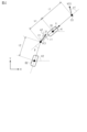
- FIG. 4 shows a model of the articulated vehicle 10 used in this embodiment.
- the pair of front wheels 22 of the tractor 20 are regarded as one front wheel C0
- the pair of rear wheels 24 of the tractor 20 are regarded as one rear wheel B1. That is, a two-wheel model is adopted for the tractor 20.
- the pair of wheels 32 of the trailer 30 is regarded as one wheel B2.
- the angle between the line defined by the front wheel C0 and the hitch point C1 and the line defined by the hitch point C1 and the wheel B2 is the hitch angle ⁇ .
- the hitch point C1 corresponds to the shaft 42 portion in FIG.
- front wheel speed VC0 which is the speed of front wheel C0
- the steering angle ⁇ 1 is quantified as the angle between the direction in which the front wheel C0 moves and a line defined by the front wheel C0 and the hitch point C1.
- the direction of vehicle speed V is parallel to the line defined by front wheel C0 and hitch point C1.
- the angle between the direction of the vehicle speed V and the x direction in FIG. 4 is an angle ⁇ 1.
- the angle between the line connecting the wheel B2 and the hitch point C1 and the x direction is an angle ⁇ 2.
- the distance l1 is the length between the front wheel C0 and the rear wheel B1.
- the distance h1 is the length between the rear wheel B1 and the hitch point C1.
- Distance l2 is the length between hitch point C1 and wheel B2.
- the direction of the speed VC1 at the hitch point C1 with respect to the direction from the wheel B2 to the hitch point C1 becomes the virtual steering angle ⁇ 2.
- the virtual steering angle ⁇ 2 becomes "-( ⁇ - ⁇ 1)".
- map data is set data of discrete values of input variables and values of output variables corresponding to each of the values of the input variables.
- the map calculation may be a process in which when the value of the input variable matches any of the values of the input variables of the map data, the value of the output variable of the corresponding map data is used as the calculation result.
- map calculation is a process in which when the value of an input variable does not match any of the values of input variables in map data, the calculation result is a value obtained by interpolating the values of multiple output variables included in map data. do it.
- the map operation will match the closest value among the values of the multiple input variables contained in the map data. It is also possible to use the value of the output variable of the map data as the calculation result.
- the PU 52 calculates a target turning angle ⁇ 1* as a manipulated variable by feedback control using the virtual steering angle ⁇ 2 as the controlled variable and the target virtual steering angle ⁇ 2* as the target value of the controlled variable (S20).
- the manipulated variable may be, for example, an output value of a proportional element whose input is the difference between the controlled variable and its target value. Further, for example, the manipulated variable may be the sum of the output value of an integral element and the output value of a proportional element that input the same difference. Further, for example, the manipulated variable may be the sum of an output value of a proportional element, an output value of an integral element, and an output value of a differential element, which input the same difference.
- the PU 52 calculates a manipulated variable for feedback control using the steered angle ⁇ 1 as the controlled variable and the target steered angle ⁇ 1* as the target controlled variable (S22). The PU 52 then operates the steering system 60 according to the amount of operation (S24).
- FIG. 5 shows a procedure for controlling the vehicle speed in the backward assist process.
- the process shown in FIG. 5 is realized by the PU 52 repeatedly executing the reverse assist program 54a at, for example, a predetermined cycle.
- the PU 52 first determines whether the vehicle is in the reverse assist control mode (S30). When determining that the vehicle is in the reverse assist control mode (S30: YES), the PU 52 acquires the user-set vehicle speed Vu (S32). The user-set vehicle speed Vu is the absolute value of the vehicle speed V of the connected vehicle 10 instructed by the driver through an input operation on the user interface 80 . Next, the PU 52 calculates the upper limit value Vth of the absolute value of the vehicle speed according to the current state of the connected vehicle 10 (S34).
- the PU 52 multiplies the minimum value of the user-set vehicle speed Vu, the upper limit value Vth, and the default value Vd by "-1" and assigns it to the target vehicle speed V* (S36).
- the reason for multiplying by "-1" is that the sign of the vehicle speed V when reversing is negative.
- the default value Vd is the upper limit of the absolute value of the vehicle speed that is predetermined from the stability margin. The stability margin in the reverse assist control mode becomes smaller as the absolute value of the vehicle speed V becomes larger. Therefore, the default value Vd is set so that the stability margin is equal to or higher than a certain value. Furthermore, the response characteristics of the steering system 60 are taken into account in the default value Vd.
- the PU 52 obtains the vehicle speed V (S38).
- the vehicle speed V is calculated by the PU 52 using at least one of the wheel speeds ⁇ w1 to ⁇ w4 detected by the wheel speed sensor 74 as input.
- the vehicle speed V may be, for example, the average value of the wheel speeds ⁇ w3 and ⁇ w4.
- the PU 52 calculates the manipulated variable for feedback control using the vehicle speed V as the controlled variable and the target vehicle speed V* as the target value of the controlled variable (S40).
- the operation amount is the driving force of the connected vehicle 10. However, the sign of the driving force can be both positive and negative. If the sign of the driving force is positive when the coupled vehicle 10 is moving backward, the driving force indicates the braking force of the coupled vehicle 10.
- the PU 52 operates the drive system 62 and the brake system 64 according to the amount of operation (S42).
- the PU52 acquires the target virtual steering angle ⁇ 2* (S50).
- the PU 52 receives the target virtual steering angle ⁇ 2* as an input and calculates the angle-dependent limit value Vth1 (S52).
- the angle-dependent limit value Vth1 is the upper limit of the absolute value of the vehicle speed V required to maintain controllability of control in which the virtual steering angle ⁇ 2 is the controlled variable and the target virtual steering angle ⁇ 2* is the target value of the controlled variable.
- the PU 52 sets the angle-dependent limit value Vth1 when the absolute value of the target virtual steering angle ⁇ 2* is large to be equal to or less than the angle-dependent limit value Vth1 when the absolute value of the target virtual steering angle ⁇ 2* is small.
- This process may be a process in which map data is stored in the storage device 54 in advance and the angle dependent limit value Vth1 is map-calculated by the PU 52.
- the map data is data that uses the absolute value of the target virtual steering angle ⁇ 2* as an input variable and uses the angle dependent limit value Vth1 as an output variable. Note that the value of the output variable included in the map data may decrease monotonically and strongly depending on the value of the input variable included in the map data.
- the PU 52 acquires the rate of change of the target virtual steering angle ⁇ 2* (S54).
- the rate of change of the target virtual steering angle ⁇ 2* is calculated by the PU 52 by inputting two or more sampled values of the target virtual steering angle ⁇ 2* acquired at mutually different timings.
- the PU 52 inputs the absolute value of the rate of change of the target virtual steering angle ⁇ 2* and calculates the speed-dependent limit value Vth2 (S56).
- the speed-dependent limit value Vth2 is an upper limit value of the vehicle speed V for suppressing a delay in following the actual virtual steering angle ⁇ 2 with respect to a change in the target virtual steering angle ⁇ 2*.
- the PU 52 sets the value of the speed dependent limit value Vth2 to one of two values depending on whether the absolute value of the rate of change of the target virtual steering angle ⁇ 2* is less than the threshold value Dth or greater than or equal to the threshold value Dth.
- the speed dependent limit value Vth2 when it is less than the threshold value Dth is larger than the speed dependent limit value Vth2 when it is equal to or more than the threshold value Dth.
- the virtual steering angle ⁇ 2 is smaller in the range in which the rate of change of the steering angle ⁇ 1 can be realized by the steering system 60.
- the range of possible values for the rate of change of is increasing.
- the jackknife hitch angle ⁇ th actually takes two values. These two jackknife hitch angles ⁇ th are stored in the storage device 54 in advance. In the process of S60, the PU 52 determines which of the two values the absolute value of the difference from the hitch angle ⁇ is smaller, depending on the sign of the steering angle ⁇ 1 and the sign of the rate of change of the steering angle ⁇ 1. Select a value.
- the PU 52 obtains the absolute value ⁇ of the difference between the target virtual steering angle ⁇ 2* and the virtual steering angle ⁇ 2 (S70).
- the absolute value ⁇ of the difference is calculated by the PU 52 using the target virtual steering angle ⁇ 2* and the virtual steering angle ⁇ 2 as input.
- the next PU 52 determines whether the restriction flag F is "1" (S72).
- the restriction flag F becomes "1” when the vehicle speed V is restricted to the small side due to the large absolute value ⁇ of the difference. Further, the restriction flag F becomes "0" when the same restriction is not applied.
- the PU 52 determines whether the absolute value ⁇ of the difference is smaller than the threshold value ⁇ th (S78). If the PU 52 determines that it is smaller than the threshold value ⁇ th (S78: YES), it increases the counter C by "1" (S80). The counter C measures the duration of time after the absolute value ⁇ of the difference switches from a state where it is greater than or equal to the threshold value ⁇ th to a state where it is less than the threshold value ⁇ th. On the other hand, when the PU 52 determines that it is equal to or greater than the threshold value ⁇ th (S78: NO), the PU 52 initializes the counter C (S82).
- the PU 52 substitutes the minimum value of the angle-dependent limit value Vth1, the speed-dependent limit value Vth2, the hitch angle-dependent limit value Vth3, and the deviation-dependent limit value Vth4 into the upper limit value Vth (S90).
- the PU 52 sets the minimum value of the absolute values of the user-set vehicle speed Vu, the upper limit value Vth, and the default value Vd as the absolute value of the target vehicle speed V*. This allows consideration of factors that cannot be expressed by the upper limit value Vth.
- the PU 52 executed the control of the virtual steering angle ⁇ 2 during the backward control of the coupled vehicle 10. Since the backward control of the coupled vehicle 10 is more difficult than the forward control, the PU 52 controls the virtual steering angle ⁇ 2 during the backward control, thereby making it possible to improve the controllability of the difficult backward control.
Landscapes
- Engineering & Computer Science (AREA)
- Transportation (AREA)
- Mechanical Engineering (AREA)
- Chemical & Material Sciences (AREA)
- Combustion & Propulsion (AREA)
- Steering Control In Accordance With Driving Conditions (AREA)
- Control Of Driving Devices And Active Controlling Of Vehicle (AREA)
Abstract
Description
「連結車両の構成」
図1に示すように、連結車両10は、トラクタ20およびトレーラ30を有している。トラクタ20は、前輪22および後輪24を備える。前輪22は右前輪および左前輪の2輪を含み、後輪24は右後輪および左後輪の2輪を含む。また、図1には、トレーラ30として、箱型のトレーラを例示する。トレーラ30は、車輪32を有している。車輪32は、右車輪および左車輪の2輪を含む。
図3に後退アシスト処理における操舵に関する処理の手順を示す。図3に示す処理は、PU52が後退アシストプログラム54aをたとえば所定周期で繰り返し実行することにより実現される。なお、以下では、先頭に「S」が付与された数字によって、各処理のステップ番号を表現する。
xc0=xb1+l1・cosθ1 …(c2)
xc1=xb1-h1・cosθ1 …(c3)
上記の式(c2),(c3)の両辺を微分した式および式(c1)を用いると、以下の式(c4)が得られる。
上記の式(c4)によれば、角度γ1が転舵角α1によって表現できる。したがって、仮想操舵角α2は、以下の式(c5)にて表現される。
すなわち、仮想操舵角α2は、ヒッチ角βおよび転舵角α1から求めることができる。
図3には、上記の式(c5)を記載しているが、実際には、記憶装置54にマップデータを記憶しておくことにより、PU52は、S18の処理において、仮想操舵角α2をマップ演算してもよい。マップデータは、ヒッチ角βおよび転舵角α1を入力変数として且つ、仮想操舵角α2を出力変数とする。
「後退アシスト処理における車速の制御」
図5に、後退アシスト処理における車速の制御に関する処理の手順を示す。図5に示す処理は、PU52が後退アシストプログラム54aをたとえば所定周期で繰り返し実行することにより実現される。
図6および図7に、S34の処理の詳細を示す。
図8A~図8Cに、トラクタ20の転舵角α1の変化速度と仮想操舵角α2の変化速度との関係の車速Vへの依存を示す。詳しくは、図8Aは、ヒッチ角βが「-40°」であって且つ転舵角α1が「-20°」の場合を示す。図8Bは、ヒッチ角βが「-40°」であって且つ転舵角α1が「0°」の場合を示す。図8Cは、ヒッチ角βが「-40°」であって且つ転舵角α1が「20°」の場合を示す。図8A~図8Cにおいて、転舵角α1の変化速度の実現可能範囲は、その大きさが「DA1」以下の範囲である。
dβ/dt
=-(V/l2)・sinβ
-{V/(l1・l2)}・(l2+h1・cosβ)・tanα …(c6)
ここで、ジャックナイフ現象が生じる場合、転舵角α1を最大値α1thとしたところで、ヒッチ角βを変化させることができない。したがって、上記の式(c6)におけるヒッチ角βの時間微分値をゼロとして且つ、転舵角α1に最大値α1thを代入したときのヒッチ角βを、ジャックナイフヒッチ角βthと見なす。ただし、転舵角α1が正および負の双方の値を取り得ることから、上記の式(c6)には、「α1th」と「(-1)・αth」との双方を代入しうる。そのため、ジャックナイフヒッチ角βthは、実際には2つの値を取る。それら2個のジャックナイフヒッチ角βthは、記憶装置54に予め記憶されている。そしてPU52は、S60の処理においては、転舵角α1の符号および転舵角α1の変化速度の符号に応じて、2個の値のうちのヒッチ角βとの差の絶対値が小さくなる方の値を選択する。
「本実施形態の作用および効果」
PU52は、後退アシスト制御中に、目標仮想操舵角α2*の絶対値、目標仮想操舵角α2*の変化速度の絶対値、差の絶対値Δ、およびヒッチ角βとジャックナイフヒッチ角βthとの差の絶対値に応じて、上限値Vthを設定した。車速Vの絶対値が小さい場合の方が大きい場合よりも、仮想操舵角α2およびヒッチ角βを所望の値に近づける制御をしやすい。そのため、本実施形態によれば、後退アシスト制御の制御性を高めることができる。
(1)PU52は、連結車両10の実際の車速の絶対値が上限値Vth以下となる条件で、運転者によって指示された車速に近づけるように制御する処理を実行した。これにより、連結車両10の車速を極力、運転者の意向に沿った車速に制御できる。
なお、本実施形態は、以下のように変更して実施することができる。本実施形態および以下の変更例は、技術的に矛盾しない範囲で互いに組み合わせて実施することができる。
・S52の処理では、目標仮想操舵角α2*の絶対値に応じて角度依存制限値Vth1の大きさを3個以上の値のうちのいずれかに選択的に設定したが、これに限らない。たとえば、目標仮想操舵角α2*の絶対値が閾値以上であるか閾値未満であるかに応じて、角度依存制限値Vth1の大きさを2通りの値のいずれかに設定してもよい。
・S56の処理では、目標仮想操舵角α2*の変化速度の絶対値が閾値Dth以上であるか否かに応じて、速度依存制限値Vth2の大きさを2個の値のうちのいずれかに設定したが、これに限らない。たとえば、速度依存制限値Vth2の大きさを3個以上の値に設定してもよい。その場合、目標仮想操舵角α2*の変化速度の絶対値が大きい場合の速度依存制限値Vth2を、目標仮想操舵角α2*の変化速度の絶対値が小さい場合の速度依存制限値Vth2以下とする。この処理は、たとえば記憶装置54にマップデータが記憶された状態でPU52によって速度依存制限値Vth2をマップ演算することによって実現してもよい。ここで、マップデータは、目標仮想操舵角α2*の変化速度の絶対値を入力変数として且つ速度依存制限値Vth2を出力変数とするデータである。
・図7に示した処理においては、目標仮想操舵角α2*と仮想操舵角α2との差の絶対値が閾値Δth以上の状態から閾値Δth未満の状態に移行してから所定時間が経過するまでは、偏差依存制限値Vth4を第1速度V1に維持したが、これに限らない。たとえば、目標仮想操舵角α2*と仮想操舵角α2との差の絶対値が閾値Δth以上の状態から閾値Δth未満の状態に切り替わったタイミングで偏差依存制限値Vth4に第0速度V0を代入してもよい。
・S58~S62の処理では、ヒッチ角依存制限値Vth3を、3個以上の値のうちのいずれかに選択的に設定したが、これに限らない。たとえば、ジャックナイフヒッチ角βthとヒッチ角βとの差の絶対値が閾値以上であるか閾値未満であるかに応じて、ヒッチ角依存制限値Vth3の大きさを2通りの値のいずれかに設定してもよい。
・上限値Vthを、角度依存制限値Vth1、速度依存制限値Vth2、偏差依存制限値Vth4、およびヒッチ角依存制限値Vth3の4つのうちの最小値を選択する処理によって定めることは必須ではない。たとえば、それら4つの値を算出した際に用いた変数を入力変数として且つ上限値Vthを出力変数とするマップデータを用いてマップ演算をしてもよい。
・仮想操舵角α2を制御量として且つ目標仮想操舵角α2*を制御量の目標値とするフィードバック制御の操作量としては、トラクタ20の前輪22の転舵角α1に限らない。たとえば下記「操舵系について」の欄に記載したように、前輪22を転舵させる装置と、後輪24を転舵させる装置とを備えた装置が操舵系の場合、トラクタ20のヨーレートの目標値を操作量としてもよい。その場合、PU52は、フィードバック制御によってヨーレートをその目標値に近づけるための操作量を、前輪22の転舵角と後輪24の転舵角とすればよい。
・たとえば後退アシスト処理において、運転者のアクセル操作およびブレーキ操作によって連結車両10の走行速度が制御されるようにしてもよい。ただし、その場合、後退アシスト処理には、車速Vが上限値Vthを超えないように制限する処理を含める。また、車速Vがデフォルト値Vdを超えないように制限する処理を含めてもよい。
・下記「操舵系について」の欄に記載したように、操舵系が上記実施形態と相違する場合、対象とする操舵系に応じてデフォルト値を設定すればよい。ここで、操舵系が複数のアクチュエータを備える場合などには、目標ヨーレートに対して安定余裕度の観点から制限を設けてもよい。これにより、安定余裕度を維持するための車速の絶対値を設計しやすくなる。
・連結車両10の操舵系としては、前輪22を転舵させる装置に限らない。たとえば、前輪22を転舵させる装置と、後輪24を転舵させる装置とを備えた装置であってもよい。またたとえば、インホイールモータを備えた装置であってもよい。
・制御装置としては、PU52と記憶装置54とを備えて、ソフトウェア処理を実行するものに限らない。たとえば、上記実施形態において実行される処理の少なくとも一部を、ハードウェア処理するたとえばASIC等の専用のハードウェア回路を備えてもよい。すなわち、制御装置は、以下の(a)~(c)のいずれかの構成であればよい。(a)上記処理の全てを、プログラムに従って実行する処理装置と、プログラムを記憶する記憶装置等のプログラム格納装置とを備える処理回路。(b)上記処理の一部をプログラムに従って実行する処理装置およびプログラム格納装置と、残りの処理を実行する専用のハードウェア回路とを備える処理回路。(c)上記処理の全てを実行する専用のハードウェア回路を備える処理回路。ここで、処理装置およびプログラム格納装置を備えたソフトウェア実行装置や、専用のハードウェア回路は複数であってもよい。
・後退アシストプログラム54a等の制御プログラムを実行するコンピュータとしては、連結車両10に搭載されたコンピュータに限らない。たとえば、連結車両10に搭載された上記PU52と、運転者の携帯端末との双方によって同コンピュータを構成してもよい。その場合、たとえば、S34の処理を携帯端末が実行してもよい。
・連結車両としては、図1に例示した車両に限らない。
なお、本明細書において、「Aが大きい場合のBをAが小さい場合のB以下にする条件を満たしつつAに応じてBの大きさを小さい側に制限する処理」において、Aが大きい場合とAが小さい場合とは、両者を比較した場合の相対的な大小関係を意味する。たとえば、「Aが大きい場合」は、「Aが第1の値」である場合に対応し、「Aが小さい場合」は、「Aが第1の値よりも小さい第2の値である場合」に対応する。そして、上記処理によれば、第1の値と第2の値との設定によっては、Aが第1の値である場合のBが、Aが第2の値である場合のBよりも小さくなることがあることを意味する。
Claims (12)
- トラクタと、前記トラクタによって牽引されるトレーラと、を備える連結車両の制御装置であって、
前記連結車両は、運転者が目標仮想操舵角を指示するためのインターフェースを備え、
前記目標仮想操舵角は、仮想操舵角の目標値であり、
前記仮想操舵角は、前記トレーラと前記トラクタとの連結箇所の進行方向を示す変数であり、
前記制御装置は、目標仮想操舵角取得処理、仮想操舵角制御処理、および車速制限処理を実行するように構成され、
前記目標仮想操舵角取得処理は、前記目標仮想操舵角を取得する処理であり、
前記仮想操舵角制御処理は、前記仮想操舵角を前記目標仮想操舵角に制御すべく前記連結車両の操舵系を操作する処理を含み、
前記車速制限処理は、前記仮想操舵角制御処理の実行中に、前記連結車両の車速の絶対値を小さい側に制限する処理であって且つ、前記目標仮想操舵角を入力として前記車速の絶対値を小さい側に制限する仮想操舵角依存処理を含む連結車両の制御装置。 - 前記目標仮想操舵角は、前記トレーラの直進方向に対する前記進行方向のなす角度を示し、
前記仮想操舵角依存処理は、前記直進方向に対する前記進行方向のなす角度の絶対値が大きい場合の前記車速の絶対値を前記なす角度の絶対値が小さい場合の前記車速の絶対値以下にする条件を満たすように、前記目標仮想操舵角に応じて前記車速の絶対値を小さい側に制限する変化速度依存処理を含む請求項1記載の連結車両の制御装置。 - 車速制限処理は、前記目標仮想操舵角の変化速度の絶対値が大きい場合の前記車速の絶対値を前記変化速度の絶対値が小さい場合の前記車速の絶対値以下にする条件を満たしつつ前記変化速度の絶対値に応じて前記車速の絶対値の大きさを小さい側に制限する変化速度依存処理を含む請求項1記載の連結車両の制御装置。
- 仮想操舵角取得処理を実行するように構成され、
前記仮想操舵角取得処理は、前記仮想操舵角を取得する処理であり、
前記仮想操舵角制御処理は、フィードバック処理を含み、
前記フィードバック処理は、フィードバック制御によって、前記仮想操舵角を前記目標仮想操舵角に近づける処理であり、
前記車速制限処理は、前記仮想操舵角と前記目標仮想操舵角との差の絶対値が大きい場合の前記車速の絶対値を、前記差の絶対値が小さい場合の前記車速の絶対値以下にする条件を満たしつつ前記差の絶対値に応じて前記車速の絶対値の大きさを小さい側に制限する偏差依存処理を含む請求項1記載の連結車両の制御装置。 - 前記偏差依存処理は、
前記仮想操舵角と前記目標仮想操舵角との差の絶対値が閾値以上となる場合の前記車速の絶対値を前記差の絶対値が前記閾値未満の場合に取り得る前記車速の絶対値の最大値よりも小さい第1速度以下に制限する処理と、
前記差の絶対値が前記閾値以上の状態から前記閾値未満の状態に移行した時点から所定期間において前記車速の絶対値を前記第1速度以下に制限する処理と、を含む請求項4記載の連結車両の制御装置。 - ヒッチ角を取得するヒッチ角取得処理を実行するように構成され、
ヒッチ角は、前記トラクタの前後方向と前記トレーラの前後方向とのなす角度であり、
前記車速制限処理は、前記ヒッチ角とジャックナイフヒッチ角との差の絶対値が小さい場合の前記車速の絶対値を前記ヒッチ角と前記ジャックナイフヒッチ角との差の絶対値が大きい場合の前記車速の絶対値以下にする条件を満たしつつ前記ヒッチ角に応じて前記車速の絶対値を制限するヒッチ角依存処理を含み、
前記ジャックナイフヒッチ角は、ジャックナイフが生じるヒッチ角である請求項1記載の連結車両の制御装置。 - 車速制御処理を実行するように構成され、
前記車速制御処理は、前記車速を制御すべく前記トラクタの駆動系を操作する処理であり、
前記車速制限処理は、前記車速制御処理によって制御される前記車速の絶対値を小さい側に制限する処理である請求項1記載の連結車両の制御装置。 - 受付処理を実行するように構成され、
前記受付処理は、前記運転者による前記車速の絶対値の指示を受け付ける処理であり、
前記車速制限処理は、前記車速の絶対値の上限値を算出する処理であり、
前記車速制御処理は、前記連結車両の実際の車速の絶対値が前記上限値以下となる条件で、前記実際の車速の絶対値を、前記運転者によって指示された前記車速の絶対値に近づけるように制御する処理を含む請求項7記載の連結車両の制御装置。 - 前記車速制御処理は、目標車速設定処理、および操作処理を含み、
前記目標車速設定処理は、前記指示された車速の絶対値、前記上限値およびデフォルト車速の絶対値のうちの最小値を目標車速の絶対値とする処理であり、
前記操作処理は、前記車速の絶対値が前記目標車速の絶対値に近づくように前記連結車両の駆動系を操作する処理である請求項8記載の連結車両の制御装置。 - 前記仮想操舵角制御処理を前記連結車両の後退制御時に実行するように構成されている請求項1記載の連結車両の制御装置。
- トラクタと、前記トラクタによって牽引されるトレーラと、を備える連結車両の制御方法であって、
前記連結車両は、運転者が目標仮想操舵角を指示するためのインターフェースを備え、
前記目標仮想操舵角は、仮想操舵角の目標値であり、
前記仮想操舵角は、前記トレーラと前記トラクタとの連結箇所の進行方向を示す変数であり、
前記制御方法は、目標仮想操舵角取得処理、仮想操舵角制御処理、および車速制限処理を実行する工程を有し、
前記目標仮想操舵角取得処理は、前記目標仮想操舵角を取得する処理であり、
前記仮想操舵角制御処理は、前記仮想操舵角を前記目標仮想操舵角に制御すべく前記連結車両の操舵系を操作する処理を含み、
前記車速制限処理は、前記仮想操舵角制御処理の実行中に、前記連結車両の車速の絶対値を小さい側に制限する処理であって且つ、前記目標仮想操舵角を入力として前記車速の絶対値を小さい側に制限する仮想操舵角依存処理を含む連結車両の制御方法。 - トラクタと、前記トラクタによって牽引されるトレーラと、を備える連結車両の制御プログラムであって、
前記連結車両は、運転者が目標仮想操舵角を指示するためのインターフェースを備え、
前記目標仮想操舵角は、仮想操舵角の目標値であり、
前記仮想操舵角は、前記トレーラと前記トラクタとの連結箇所の進行方向を示す変数であり、
前記制御プログラムは、目標仮想操舵角取得処理、仮想操舵角制御処理、および車速制限処理をコンピュータに実行させる指令を含み、
前記目標仮想操舵角取得処理は、前記目標仮想操舵角を取得する処理であり、
前記仮想操舵角制御処理は、前記仮想操舵角を前記目標仮想操舵角に制御すべく前記連結車両の操舵系を操作する処理を含み、
前記車速制限処理は、前記仮想操舵角制御処理の実行中に、前記連結車両の車速の絶対値を小さい側に制限する処理であって且つ、前記目標仮想操舵角を入力として前記車速の絶対値を小さい側に制限する仮想操舵角依存処理を含む連結車両の制御プログラム。
Priority Applications (2)
| Application Number | Priority Date | Filing Date | Title |
|---|---|---|---|
| CN202380046397.5A CN119365375A (zh) | 2022-06-17 | 2023-05-26 | 连结车辆的控制装置、连结车辆的控制方法、以及连结车辆的控制程序 |
| EP23823667.3A EP4541675A4 (en) | 2022-06-17 | 2023-05-26 | COUPLED VEHICLE CONTROL DEVICE, COUPLED VEHICLE CONTROL METHOD, AND COUPLED VEHICLE CONTROL PROGRAM |
Applications Claiming Priority (2)
| Application Number | Priority Date | Filing Date | Title |
|---|---|---|---|
| JP2022-098166 | 2022-06-17 | ||
| JP2022098166A JP2023184174A (ja) | 2022-06-17 | 2022-06-17 | 連結車両の制御装置、連結車両の制御方法、および連結車両の制御プログラム |
Publications (1)
| Publication Number | Publication Date |
|---|---|
| WO2023243368A1 true WO2023243368A1 (ja) | 2023-12-21 |
Family
ID=89191232
Family Applications (1)
| Application Number | Title | Priority Date | Filing Date |
|---|---|---|---|
| PCT/JP2023/019725 Ceased WO2023243368A1 (ja) | 2022-06-17 | 2023-05-26 | 連結車両の制御装置、連結車両の制御方法、および連結車両の制御プログラム |
Country Status (4)
| Country | Link |
|---|---|
| EP (1) | EP4541675A4 (ja) |
| JP (1) | JP2023184174A (ja) |
| CN (1) | CN119365375A (ja) |
| WO (1) | WO2023243368A1 (ja) |
Families Citing this family (1)
| Publication number | Priority date | Publication date | Assignee | Title |
|---|---|---|---|---|
| JP2026054071A (ja) * | 2024-09-13 | 2026-03-26 | 株式会社ジェイテクト | 連結車両の制御装置、連結車両の制御方法、および連結車両の制御プログラム |
Citations (5)
| Publication number | Priority date | Publication date | Assignee | Title |
|---|---|---|---|---|
| JP2002274353A (ja) * | 2001-03-16 | 2002-09-25 | Nissan Motor Co Ltd | 車両用制駆動力制御装置 |
| US20160229452A1 (en) * | 2015-02-10 | 2016-08-11 | Ford Global Technologies, Llc | Speed optimized trajectory control for motor vehicles |
| JP2017502867A (ja) * | 2013-11-18 | 2017-01-26 | ローベルト ボツシユ ゲゼルシヤフト ミツト ベシユレンクテル ハフツングRobert Bosch Gmbh | 牽引車両のためのベクトルベースのドライバアシスタンス |
| JP2020001576A (ja) * | 2018-06-28 | 2020-01-09 | アイシン精機株式会社 | 運転支援装置 |
| JP2021091264A (ja) * | 2019-12-09 | 2021-06-17 | フォルシアクラリオン・エレクトロニクス株式会社 | 牽引支援装置 |
Family Cites Families (2)
| Publication number | Priority date | Publication date | Assignee | Title |
|---|---|---|---|---|
| DE102014002856B4 (de) * | 2014-02-27 | 2016-08-11 | Audi Ag | Verfahren zur Steuerung einer Fahrt eines Kraftfahrzeugs und Kraftfahrzeug |
| US9981662B2 (en) * | 2015-10-15 | 2018-05-29 | Ford Global Technologies, Llc | Speed limiting comfort enhancement |
-
2022
- 2022-06-17 JP JP2022098166A patent/JP2023184174A/ja active Pending
-
2023
- 2023-05-26 WO PCT/JP2023/019725 patent/WO2023243368A1/ja not_active Ceased
- 2023-05-26 EP EP23823667.3A patent/EP4541675A4/en active Pending
- 2023-05-26 CN CN202380046397.5A patent/CN119365375A/zh active Pending
Patent Citations (6)
| Publication number | Priority date | Publication date | Assignee | Title |
|---|---|---|---|---|
| JP2002274353A (ja) * | 2001-03-16 | 2002-09-25 | Nissan Motor Co Ltd | 車両用制駆動力制御装置 |
| JP2017502867A (ja) * | 2013-11-18 | 2017-01-26 | ローベルト ボツシユ ゲゼルシヤフト ミツト ベシユレンクテル ハフツングRobert Bosch Gmbh | 牽引車両のためのベクトルベースのドライバアシスタンス |
| US20160229452A1 (en) * | 2015-02-10 | 2016-08-11 | Ford Global Technologies, Llc | Speed optimized trajectory control for motor vehicles |
| US10286950B2 (en) | 2015-02-10 | 2019-05-14 | Ford Global Technologies, Llc | Speed optimized trajectory control for motor vehicles |
| JP2020001576A (ja) * | 2018-06-28 | 2020-01-09 | アイシン精機株式会社 | 運転支援装置 |
| JP2021091264A (ja) * | 2019-12-09 | 2021-06-17 | フォルシアクラリオン・エレクトロニクス株式会社 | 牽引支援装置 |
Non-Patent Citations (1)
| Title |
|---|
| See also references of EP4541675A4 |
Also Published As
| Publication number | Publication date |
|---|---|
| EP4541675A4 (en) | 2025-08-27 |
| CN119365375A (zh) | 2025-01-24 |
| EP4541675A1 (en) | 2025-04-23 |
| JP2023184174A (ja) | 2023-12-28 |
Similar Documents
| Publication | Publication Date | Title |
|---|---|---|
| JP6269557B2 (ja) | 車両の運転支援制御装置 | |
| US9669866B2 (en) | Steering intention determination device, vehicle control device, steering assist device, and steering assist system | |
| JP4341665B2 (ja) | 車両操舵制御装置 | |
| WO2014128818A1 (ja) | 車両用操舵制御装置及び車両用操舵制御方法 | |
| WO2014167629A1 (ja) | 操舵制御装置および操舵制御方法 | |
| JP2022523577A (ja) | 車両安定化システムおよびその動作方法 | |
| JP5359200B2 (ja) | 車両操舵制御装置 | |
| WO2023228854A1 (ja) | 連結車両の制御装置、連結車両の制御方法、および連結車両の制御プログラム | |
| WO2023243368A1 (ja) | 連結車両の制御装置、連結車両の制御方法、および連結車両の制御プログラム | |
| JP4639985B2 (ja) | 車両の操舵制御装置 | |
| JP2016215864A (ja) | 電動パワーステアリング装置 | |
| JP2010155561A (ja) | 車両制御装置及び車両制御方法 | |
| JP4100223B2 (ja) | 車両用操舵制御装置 | |
| WO2023223837A1 (ja) | 連結車両の制御装置、連結車両の制御方法、および連結車両の制御プログラム | |
| JP2023114989A (ja) | パワーステアリングシステムのギア比を車両速度及びハンドル角の関数として決定する方法 | |
| JP5515782B2 (ja) | 操舵装置 | |
| WO2024042969A1 (ja) | 連結車両の制御装置、連結車両の制御方法、および連結車両の制御プログラム | |
| JP7402216B2 (ja) | 車両の補助ステアリングシステムにおける補助機能適用の重み付け | |
| JP5407298B2 (ja) | 車両用操舵装置およびその制御方法 | |
| JP2006282067A (ja) | 車両用操舵制御装置 | |
| JP7812946B2 (ja) | 連結車両の制御装置、連結車両の制御方法、および連結車両の制御プログラム | |
| JP7780042B2 (ja) | 連結車両のジャックナイフ対策装置、連結車両のジャックナイフ対策方法、および連結車両のジャックナイフ対策プログラム | |
| JP5228937B2 (ja) | 挙動制御装置 | |
| JP2014151882A (ja) | 車両用操舵制御装置及び車両用操舵制御方法 | |
| JP2008024183A (ja) | 操舵装置 |
Legal Events
| Date | Code | Title | Description |
|---|---|---|---|
| 121 | Ep: the epo has been informed by wipo that ep was designated in this application |
Ref document number: 23823667 Country of ref document: EP Kind code of ref document: A1 |
|
| WWE | Wipo information: entry into national phase |
Ref document number: 202380046397.5 Country of ref document: CN |
|
| WWE | Wipo information: entry into national phase |
Ref document number: 2023823667 Country of ref document: EP |
|
| NENP | Non-entry into the national phase |
Ref country code: DE |
|
| WWP | Wipo information: published in national office |
Ref document number: 202380046397.5 Country of ref document: CN |
|
| ENP | Entry into the national phase |
Ref document number: 2023823667 Country of ref document: EP Effective date: 20250117 |
|
| WWP | Wipo information: published in national office |
Ref document number: 2023823667 Country of ref document: EP |