WO2023243473A1 - Optical element - Google Patents
Optical element Download PDFInfo
- Publication number
- WO2023243473A1 WO2023243473A1 PCT/JP2023/020916 JP2023020916W WO2023243473A1 WO 2023243473 A1 WO2023243473 A1 WO 2023243473A1 JP 2023020916 W JP2023020916 W JP 2023020916W WO 2023243473 A1 WO2023243473 A1 WO 2023243473A1
- Authority
- WO
- WIPO (PCT)
- Prior art keywords
- faraday rotation
- rotation element
- optical element
- faraday
- magnet
- Prior art date
- Legal status (The legal status is an assumption and is not a legal conclusion. Google has not performed a legal analysis and makes no representation as to the accuracy of the status listed.)
- Ceased
Links
Images





Classifications
-
- G—PHYSICS
- G02—OPTICS
- G02F—OPTICAL DEVICES OR ARRANGEMENTS FOR THE CONTROL OF LIGHT BY MODIFICATION OF THE OPTICAL PROPERTIES OF THE MEDIA OF THE ELEMENTS INVOLVED THEREIN; NON-LINEAR OPTICS; FREQUENCY-CHANGING OF LIGHT; OPTICAL LOGIC ELEMENTS; OPTICAL ANALOGUE/DIGITAL CONVERTERS
- G02F1/00—Devices or arrangements for the control of the intensity, colour, phase, polarisation or direction of light arriving from an independent light source, e.g. switching, gating or modulating; Non-linear optics
- G02F1/01—Devices or arrangements for the control of the intensity, colour, phase, polarisation or direction of light arriving from an independent light source, e.g. switching, gating or modulating; Non-linear optics for the control of the intensity, phase, polarisation or colour
- G02F1/09—Devices or arrangements for the control of the intensity, colour, phase, polarisation or direction of light arriving from an independent light source, e.g. switching, gating or modulating; Non-linear optics for the control of the intensity, phase, polarisation or colour based on magneto-optical elements, e.g. exhibiting Faraday effect
- G02F1/093—Devices or arrangements for the control of the intensity, colour, phase, polarisation or direction of light arriving from an independent light source, e.g. switching, gating or modulating; Non-linear optics for the control of the intensity, phase, polarisation or colour based on magneto-optical elements, e.g. exhibiting Faraday effect used as non-reciprocal devices, e.g. optical isolators, circulators
-
- G—PHYSICS
- G02—OPTICS
- G02B—OPTICAL ELEMENTS, SYSTEMS OR APPARATUS
- G02B27/00—Optical systems or apparatus not provided for by any of the groups G02B1/00 - G02B26/00, G02B30/00
- G02B27/28—Optical systems or apparatus not provided for by any of the groups G02B1/00 - G02B26/00, G02B30/00 for polarising
- G02B27/286—Optical systems or apparatus not provided for by any of the groups G02B1/00 - G02B26/00, G02B30/00 for polarising for controlling or changing the state of polarisation, e.g. transforming one polarisation state into another
-
- G—PHYSICS
- G02—OPTICS
- G02B—OPTICAL ELEMENTS, SYSTEMS OR APPARATUS
- G02B5/00—Optical elements other than lenses
- G02B5/30—Polarising elements
- G02B5/3025—Polarisers, i.e. arrangements capable of producing a definite output polarisation state from an unpolarised input state
-
- G—PHYSICS
- G02—OPTICS
- G02B—OPTICAL ELEMENTS, SYSTEMS OR APPARATUS
- G02B7/00—Mountings, adjusting means, or light-tight connections, for optical elements
- G02B7/008—Mountings, adjusting means, or light-tight connections, for optical elements with means for compensating for changes in temperature or for controlling the temperature; thermal stabilisation
-
- G—PHYSICS
- G02—OPTICS
- G02F—OPTICAL DEVICES OR ARRANGEMENTS FOR THE CONTROL OF LIGHT BY MODIFICATION OF THE OPTICAL PROPERTIES OF THE MEDIA OF THE ELEMENTS INVOLVED THEREIN; NON-LINEAR OPTICS; FREQUENCY-CHANGING OF LIGHT; OPTICAL LOGIC ELEMENTS; OPTICAL ANALOGUE/DIGITAL CONVERTERS
- G02F1/00—Devices or arrangements for the control of the intensity, colour, phase, polarisation or direction of light arriving from an independent light source, e.g. switching, gating or modulating; Non-linear optics
- G02F1/01—Devices or arrangements for the control of the intensity, colour, phase, polarisation or direction of light arriving from an independent light source, e.g. switching, gating or modulating; Non-linear optics for the control of the intensity, phase, polarisation or colour
- G02F1/09—Devices or arrangements for the control of the intensity, colour, phase, polarisation or direction of light arriving from an independent light source, e.g. switching, gating or modulating; Non-linear optics for the control of the intensity, phase, polarisation or colour based on magneto-optical elements, e.g. exhibiting Faraday effect
Definitions
- the present invention relates to an optical element.
- One aspect of the present invention aims to realize a Faraday rotator that is small, inexpensive, and can withstand high-output, high-repetition lasers.
- an optical element includes a reflective Faraday rotation element that rotates the polarization plane of reflected light with respect to the polarization plane of incident light, and a
- the device includes a magnet provided on the opposite side of a surface on which incident light enters, and a cooling section provided between the Faraday rotation element and the magnet, and the cooling section cools the Faraday rotation element.
- FIG. 3 is a configuration diagram showing the configuration of main parts of another optical system including an optical element according to Embodiment 2.
- FIG. FIG. 7 is a configuration diagram showing the configuration of main parts of an optical system including an optical element according to a third embodiment.
- FIG. 7 is a configuration diagram showing the configuration of main parts of an optical system including an optical element according to a fourth embodiment.
- FIG. 2 is a schematic cross-sectional view showing the configuration of an optical element according to a comparative example.
- Embodiment 1 Prior to describing Embodiment 1 of the present invention, a comparative example will first be described.
- FIG. 11 is a schematic cross-sectional view showing the configuration of an optical element 200 according to a comparative example.
- the optical element 200 is an optical element that includes a donut-shaped magnet 230 and a Faraday rotation element 210 in the center where the magnetic field of the magnet 230 is concentrated.
- the light incident on the optical element 200 rotates the plane of polarization of the incident light by the magnetic field of the magnet 230 acting on the Faraday rotation element 210, and then passes through the optical element 200.
- the optical element 200 is used at room temperature.
- the optical element 200 has a structure that easily traps heat. Therefore, heat is accumulated by the incident laser, resulting in a large thermal lens effect and a large thermal birefringence effect. Therefore, optical element 200 is not suitable for continuous use. Furthermore, since the plane of polarization is rotated while transmitting the laser, one optical element 200 is required for each optical path.
- the mirror 120 is a mirror that reflects light, and the surface (back surface) opposite to the surface on which the incident light enters the Faraday rotation element 110 is coated with a mirror. Therefore, the mirror 120 reflects the light incident on the Faraday rotation element 110 and makes the reflected light pass through the Faraday rotation element again.
- the mirror 120 may be a thin film layer in which metal is deposited on one surface of the Faraday rotation element 110 (the surface opposite to the surface on which the incident light is incident).
- the mirror 120 may be a multilayer film of an inorganic oxide such as SiO 2 or ZrO 2 stacked on one surface of the Faraday rotation element 110.
- the light incident on the optical element 100 is reflected by the mirror 120 and passes through the Faraday rotation element 110 twice. Therefore, the optical element 100 can rotate the plane of polarization twice as much as when the light is simply incident on a Faraday rotation element and transmitted.
- the magnet 130 is a magnet provided on the opposite side of the Faraday rotation element to the surface on which the incident light enters.
- the magnet 130 is a so-called slab-type magnet, and has an S-pole surface and an N-pole surface.
- the magnet 130 is arranged so that the S-pole or N-pole surface of the magnet 130 is parallel to the surface of the Faraday rotation element on which the incident light is incident. That is, in the Faraday rotation element, the magnetic field by the magnet 130 is oriented perpendicular to the plane on which the incident light enters the Faraday rotation element 110.
- An example of the magnet 130 is a block-shaped magnet of 50 x 50 (size of a surface parallel to the Faraday rotation element 110) x 48 (thickness) mm, and has a magnetic force of 0.4T.
- the surface of the magnet 130 with the magnetic poles may be larger than the beam aperture.
- the surface of the magnet 130 having the magnetic poles may be larger than the surface of the Faraday rotation element 110 on which the incident light is incident.
- the refrigerant circulation section 140 is provided between the Faraday rotation element 110 and the magnet 130.
- the refrigerant circulation section 140 is in contact with the mirror 120.
- the refrigerant circulation unit 140 has piping that circulates the refrigerant therein.
- the coolant circulation unit 140 has a role of absorbing the heat of the Faraday rotation element 110 via the mirror 120 and cooling the Faraday rotation element 110. It is preferable to use liquid nitrogen or liquid helium as the coolant.
- the refrigerant circulation unit 140 is made of a material with high thermal conductivity, such as copper, sapphire, or other metal.
- the cryostat 150 is a container that includes all other components of the optical element 100, and cools the inside thereof.
- the method of cooling the cryostat is not particularly limited.
- the cryostat 150 is provided with a window that transmits light for entering and/or emitting a laser.
- the cryostat 150 may use liquid nitrogen or liquid helium.
- FIG. 2 shows the measurement results of the magnetic flux density (vertical axis) according to the distance from the center of the magnet 130 (horizontal axis). That is, in FIG. 2, the distance Z from the surface (S pole or N pole) of the magnet 130 is changed, and the distribution of magnetic flux density on the plane is measured.
- the thickness of the Faraday rotation element 110 in the optical element 100 is 5 mm
- a substantially uniform magnetic flux density of about 0.45 T is obtained in a 20 mm width region of the surface of the Faraday rotation element 110 on which the incident light enters.
- the thickness of the Faraday rotation element 110 is 10 mm
- a substantially uniform magnetic flux density of about 0.35 T is obtained in a 20 mm width region of the surface of the Faraday rotation element 110 on which the incident light enters.
- a second polarizing plate (not shown) was provided on the exit side of the reflected light, and a power meter (not shown) was provided on the secondary side thereof.
- the angle of the polarizing plate 3 is measured. From these angular differences, it can be determined how much the polarization plane of the reflected light has rotated with respect to the polarization plane of the incident light.
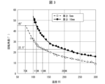
- FIG. 3 shows experimental results showing the transition of the rotation angle of the plane of polarization when the temperature is changed.
- the horizontal axis is temperature (K) and the vertical axis is the rotation angle (°) of the plane of polarization.
- the experiment was conducted using a Faraday rotation element 110 with a thickness of 5 mm and a thickness of 10 mm. Further, the incident angle of light to the Faraday rotation element 110 was set to 5°.
- the optical element 100 can be suitably used as an isolator or the like.
- FIG. 4 shows experimental results showing the distribution of power intensity for each polarization angle.
- the horizontal axis is the rotation angle (°) of the plane of polarization
- the vertical axis is the measured value of power intensity (a.u.).
- the experiment was conducted using a 10 mm Faraday rotation element, and the temperature of the Faraday rotation element 110 was measured at 300K and 110K. As shown in FIG. 4, a sine wave is obtained.
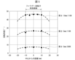
- FIG. 5 shows experimental results showing the distribution of the rotation angle of the laser spot in the radial direction.
- the horizontal axis represents the distance (mm) of the laser spot from the center of the magnet 130 (the center of the Faraday rotation element 110), and the vertical axis represents the rotation angle (°) of the plane of polarization.
- the experiments were conducted in a 110K environment using a Faraday rotation element of 10 mm, and in a 110K environment and a 300K environment using a Faraday rotation element with a thickness of 5 mm.
- the Faraday rotation element 110 rotates the polarization plane of reflected light with respect to the polarization plane of incident light due to the Faraday effect.
- the Verdet constant is known as a proportionality constant for determining the rotation angle at this time.
- FIG. 6 shows the Verdet constant (rad/Tm) of TGG versus temperature (K).
- the Verdet constant is inversely proportional to absolute temperature.
- the Verdet constant it is 35 rad/Tm at 300K, 60 rad/Tm at 200K, 110 rad/Tm at 100K, and 165 rad/Tm at 70K. Therefore, it is important to cool the Faraday rotation element 110.
- the optical element 100 according to the first embodiment has a weight of about 1/60 and a magnetic force of about 1/2 to 1/3 than the optical element 200 according to the comparative example, so it is small and inexpensive. As a result, the optical element 100 can be forcibly cooled by the cooling section. Furthermore, since it is cooled, unlike the comparative example, the heat generated by the laser does not remain, and the thermal lens effect and thermal birefringence effect are also small. Therefore, it can be used with high output and high repetition rate.
- the refrigerant circulation unit 140 is plane-connected to the Faraday rotation element 110 via a thin film mirror 120. Therefore, the coolant circulation unit 140 can quickly remove a large amount of heat generated by the laser from the Faraday rotary element 110. Therefore, the optical element 100 can be used with high output and high repetition.
- FIG. 7 is a configuration diagram showing the configuration of main parts of an optical system 1a including an optical element 100a according to the second embodiment.
- FIG. 8 is a configuration diagram showing the configuration of main parts of another optical system 1b including the optical element 100a according to the second embodiment.
- the optical element 100a includes Faraday rotation elements 110a and 110b, mirrors 120a and 120b, a magnet 130, a coolant circulation section 140, and a cryostat 150.
- one Faraday rotation element 110 is arranged so as to face either the S pole or the N pole of the magnet 130.
- one Faraday rotation element 110a, 110b is arranged at each of the S pole and the N pole.
- FIG. 9 is a configuration diagram showing the configuration of main parts of an optical system 1c including an optical element 100b according to the third embodiment.
- an optical element 100b according to the third embodiment differs from the first embodiment in that, unlike the optical element 100, it includes a heating section 170 that heats a coolant circulation section 140.
- the heating section 170 has a function of heating the refrigerant circulation section 140. That is, a heating unit 170 such as a heater is fixed to a copper block in which piping for passing refrigerant is formed. As a result, it is also possible to heat the Faraday rotary element 110, whose temperature monotonically decreases to the temperature of the refrigerant, by the refrigerant. Therefore, it becomes possible to constantly control (fix) the temperature to a predetermined temperature.
- the heat dissipation section 180 is a heat dissipation plate that is in contact with the surface of the Faraday rotation element 110 on which the incident light is incident, and radiates the heat of the Faraday rotation element 110.
- As the heat dissipation section 180 sapphire or the like can be used.
- the wavelength that is incident on the optical element 100 is not particularly limited. Naturally, if the wavelengths are different, the Verdet constants will also be different. Therefore, the temperature, the thickness of the Faraday rotation element, etc. are not limited to the various experimental results shown in the first embodiment.
- an optical element includes a reflective Faraday rotation element that rotates a polarization plane of reflected light with respect to a polarization plane of incident light;
- the device includes a magnet provided on the opposite side of a surface on which incident light enters, and a cooling section provided between the Faraday rotation element and the magnet, and the cooling section cools the Faraday rotation element.
- a Faraday rotator (optical element) that achieves a high Verdet constant can be obtained by providing a cooling part for cooling the Faraday rotator element between the Faraday rotator element and the magnet.
- it since it is a reflective Faraday rotator, it can rotate the plane of polarization separately during incidence and reflection, so it only needs half the length of the conventional type, making the magnet smaller and allowing Faraday rotation.
- the optical element can be made thinner, and the optical element can be made smaller.
- an optical element includes a reflective Faraday rotation element that rotates the polarization plane of reflected light with respect to the polarization plane of incident light, and a
- the device includes a magnet provided on the opposite side of the surface on which the incident light enters, and a cooling unit that cools the Faraday rotation element to 200K or less.
- the optical element according to Aspect 6 of the present invention may further include a heating section that heats the Faraday rotation element in any one of Aspects 1 to 5 above.
- the cooling capacity of the Faraday rotator element can be improved by the heat radiation part, and a Faraday rotator having a high Verdet constant can be realized.
- the Faraday rotation element is referred to as a first Faraday rotation element, and the optical element is provided on the opposite side of the first Faraday rotation element with respect to the magnet.
- the device may further include a reflective second Faraday rotation element that rotates the polarization plane of the reflected light with respect to the polarization plane of the incident light.
- two Faraday rotation elements can be arranged for one magnet, and the optical system can be made smaller and lower in cost.
- An optical element according to aspect 9 of the present invention is an optical element according to aspect 8, which reflects or refracts the reflected light from the first Faraday rotation element and makes it the incident light to the second Faraday rotation element. You may prepare.
Landscapes
- Physics & Mathematics (AREA)
- General Physics & Mathematics (AREA)
- Optics & Photonics (AREA)
- Nonlinear Science (AREA)
- Engineering & Computer Science (AREA)
- Power Engineering (AREA)
Abstract
Description
本発明は光学素子に関する。 The present invention relates to an optical element.
特許文献1では、ファラデー回転素子に対して熱伝導率が高く、複屈折を有しない放熱基板をファラデー回転素子に接合させ、ファラデー回転素子の熱を放熱している。
In
ここで、高出力・高繰り返しのレーザに耐え得るファラデー回転子は大型で高コストになる傾向がある。そのため、ファラデー回転子が高出力・高繰り返しのレーザ開発における大きな障害の一つとなっている。 Here, Faraday rotators that can withstand high-output, high-repetition lasers tend to be large and expensive. Therefore, the Faraday rotator has become one of the major obstacles in the development of high-output, high-repetition lasers.
本発明の一態様は、小型で安価な、高出力・高繰り返しのレーザに耐え得るファラデー回転子を実現することを目的とする。 One aspect of the present invention aims to realize a Faraday rotator that is small, inexpensive, and can withstand high-output, high-repetition lasers.
上記の課題を解決するために、本発明の一態様に係る光学素子は、入射光の偏光面に対し反射光の偏光面を回転させる反射型のファラデー回転素子と、前記ファラデー回転素子に対し前記入射光が入射する面の反対側に設けられた磁石と、前記ファラデー回転素子と前記磁石との間に設けられた冷却部と、を備え、前記冷却部は、前記ファラデー回転素子を冷却する。 In order to solve the above problems, an optical element according to one aspect of the present invention includes a reflective Faraday rotation element that rotates the polarization plane of reflected light with respect to the polarization plane of incident light, and a The device includes a magnet provided on the opposite side of a surface on which incident light enters, and a cooling section provided between the Faraday rotation element and the magnet, and the cooling section cools the Faraday rotation element.
本発明の一態様によれば、小型で安価な、高出力・高繰り返しのレーザに耐え得るファラデー回転子を実現できる。 According to one aspect of the present invention, it is possible to realize a Faraday rotator that is small, inexpensive, and can withstand high-output, high-repetition lasers.
〔実施形態1〕
本発明の実施形態1の説明に先立ち、比較例をまず説明する。
[Embodiment 1]
Prior to describing
(比較例)
図11は、比較例に係る光学素子200の構成を示す概略断面図である。光学素子200は、ドーナツ状の磁石230と、磁石230の磁場が集中する中央部にファラデー回転素子210とが設けられた光学素子である。光学素子200への入射光は、磁石230の磁場がファラデー回転素子210に作用することによって、当該入射光の偏光面を回転させたうえで、光学素子200を透過していく。光学素子200は常温で用いられる。
(Comparative example)
FIG. 11 is a schematic cross-sectional view showing the configuration of an
光学素子200の一例としては、直径236mmで高さ240mmほどの円柱形状をしており、重量としては80kgほどある。重量のうち、大部分が中心部において1.5Tの磁力を生成する磁石230の重量である。そのため、非常に大きく重いため、コストがかかる。ここで、300Kにおけるベルデ定数は35rad/Tmである。
An example of the
さらに、光学素子200は、熱が籠りやすい構造をしている。このため、入射したレーザによって熱を蓄熱し、大きな熱レンズ効果と大きな熱複屈折効果とが生じる。そのため、光学素子200は、連続使用に適していない。また、レーザを透過させながら偏光面を回転させるため、1光路につき、光学素子200が1個必要になる。
Furthermore, the
(光学系1の構成)
以下、本発明の一実施形態について、図1~6を参照し、詳細に説明する。
(Configuration of optical system 1)
Hereinafter, one embodiment of the present invention will be described in detail with reference to FIGS. 1 to 6.
図1は、実施形態1に係る光学素子100を含む、光学系1の要部の構成を示す構成図である。光学系1は、レーザ光源2と偏光板3と、光学素子100とを備える。
FIG. 1 is a configuration diagram showing the configuration of main parts of an
レーザ光源2は、高出力・高繰り返しのレーザ光源であり、例えば1パルス当たりのエネルギー100J,パルス頻度100Hzのレーザ(波長1030nm)を出射するレーザ光源(YAG)である。偏光板3は、レーザ光源2から出射された出射光を特定方向の偏光のみを通過させることで、出射光の偏光状態を良質にするための光学素子である。
The
光学素子100は、反射型のファラデー回転素子110を含む光学素子である。光学素子100は、入射光の偏光面に対し、反射光の偏光面を回転させる機能を有する。
The
(光学素子100の構成)
光学素子100は、ファラデー回転素子110と、ミラー120と、磁石130と、冷媒循環部140(冷却部)と、クライオスタット150(冷却部)と、を備える。
(Configuration of optical element 100)
The
ファラデー回転素子110は、透過する光の偏光面を、印加されている磁場に応じて回転させる。ファラデー回転素子110は、光学素子100に入射した光を入射させる。ファラデー回転素子110としては、TGG(Tb3Ga5O12:Terbium Gallium Garnet)単結晶を用いてもよく、他のファラデー回転を生じる物体、例えば、TAG(Tb3Al5O12)、TSAG(Tb3Sc2Al3O12)、ガラス材料のFR-5(HOYA)、およびFR25N等が挙げられる。
The Faraday
また、ミラー120は、光を反射するミラーであり、ファラデー回転素子110に対し入射光が入射する面の反対側の面(背面)にミラーコートされている。そのため、ミラー120は、ファラデー回転素子110への入射光を反射し、再度ファラデー回転素子を通過する反射光とする。ミラー120は、ファラデー回転素子110の一面(入射光が入射する面の反対面)に金属を蒸着した薄膜層であってもよい。または、ミラー120は、ファラデー回転素子110の一面に積層されたSiO2またはZrO2等の無機酸化物の多層膜であってもよい。
Further, the
つまり、光学素子100に入射した光は、ミラー120による反射によって、2度ファラデー回転素子110を透過する。そのため、光学素子100は、ただファラデー回転素子に入射させ透過させた場合よりも偏光面を2倍回転させることができる。
In other words, the light incident on the
磁石130は、ファラデー回転素子に対し入射光が入射する面の反対側に設けられている磁石である。磁石130は、いわゆるスラブ型の磁石であり、S極の面とN極の面とを有する。磁石130のS極またはN極の面が、ファラデー回転素子における入射光が入射する面と平行になるように磁石130は配置される。すなわち、ファラデー回転素子において、磁石130による磁場は、ファラデー回転素子110における入射光が入射する面に対して垂直に向いている。磁石130の一例としては、50×50(ファラデー回転素子110に対して平行な面の大きさ)×48(厚さ)mmのブロック状の磁石であり、0.4Tの磁力を有する。光の光路において均一な磁場を生成するために、磁石130の磁極を有する面は、ビーム口径より大きくてもよい。さらに、磁石130の磁極を有する面は、ファラデー回転素子110における入射光が入射する面より大きくてもよい。
The
冷媒循環部140は、ファラデー回転素子110と磁石130との間に設けられる。冷媒循環部140は、ミラー120に接している。冷媒循環部140は、内部に冷媒を通し循環させる配管を有する。冷媒循環部140は、ミラー120を介してファラデー回転素子110の熱を吸収し、ファラデー回転素子110を冷却する役割をもつ。冷媒としては、液体窒素または液体ヘリウムを用いることが好ましい。冷媒循環部140としては熱伝導率が高い材質、例えば銅、サファイア、または他の金属を用いることが好ましい。
The
クライオスタット150は、光学素子100の他の構成要素を全て含む容器であり、その中を冷却している。クライオスタットの冷却方法は特に限定されない。クライオスタット150には、レーザを入射および/または出射するための光を透過する窓が設けられている。クライオスタット150としては、液体窒素または液体ヘリウムを用いるものであってもよい。
The
(磁力計測結果)
図2は、磁石130の中心からの距離(横軸)に応じた、磁束密度(縦軸)の測定結果である。つまり、図2では、磁石130の面(S極またはN極)からの距離Zを変化させ、平面上の磁束密度の分布を計測している。光学素子100におけるファラデー回転素子110の厚さが5mm厚の場合、ファラデー回転素子110における入射光が入射する面の幅20mmの領域において、略均一な約0.45Tの磁束密度が得られる。ファラデー回転素子110の厚さが10mm厚の場合、ファラデー回転素子110における入射光が入射する面の幅20mmの領域において、略均一な約0.35Tの磁束密度が得られる。
(Magnetic force measurement results)
FIG. 2 shows the measurement results of the magnetic flux density (vertical axis) according to the distance from the center of the magnet 130 (horizontal axis). That is, in FIG. 2, the distance Z from the surface (S pole or N pole) of the
以降、本実施形態に係る光学素子100における、この磁場環境下でのファラデー回転の効果を確認していく。
Hereinafter, we will confirm the effect of Faraday rotation in the
(偏光面の回転角度の検証)
入射光に対する反射光の偏光面の回転角度を検証するにあたり、反射光の出口側に、第2の偏光板(図示省略)と、その2次側にパワーメータ(図示省略)とを設けた。パワーメータによる反射光のパワーの計測値が最大になるように、第2の偏光板の偏光面を操作し、パワーの計測値が最大になったときの第2の偏光面の角度を計測する。また、偏光板3の角度を計測する。これらの角度差から、入射光の偏光面に対し、反射光の偏光面がどれだけ回転したかがわかる。
(Verification of rotation angle of polarization plane)
In order to verify the rotation angle of the polarization plane of the reflected light with respect to the incident light, a second polarizing plate (not shown) was provided on the exit side of the reflected light, and a power meter (not shown) was provided on the secondary side thereof. Manipulate the polarization plane of the second polarizing plate so that the power measurement value of the reflected light by the power meter is maximized, and measure the angle of the second polarization plane when the power measurement value becomes maximum. . Also, the angle of the
図3は、温度を変化させたときにおける偏光面の回転角度の遷移を示す実験結果である。図3において、横軸は温度(K)、縦軸は偏光面の回転角度(°)である。図3に示すように、実験はファラデー回転素子110の厚さが5mmのものと10mmのもので行った。また、ファラデー回転素子110に対する光の入射角は5°とした。
FIG. 3 shows experimental results showing the transition of the rotation angle of the plane of polarization when the temperature is changed. In FIG. 3, the horizontal axis is temperature (K) and the vertical axis is the rotation angle (°) of the plane of polarization. As shown in FIG. 3, the experiment was conducted using a
図3に示すようにファラデー回転素子110の厚さが5mmの場合は、130Kで22.5°回転しており、75Kで45°回転するであろうことがわかった。また、ファラデー回転素子110の厚さが10mmの場合は、200Kで22.5°回転しており、110Kで45°回転していることがわかった。それゆえ、光学素子100は、アイソレータ等として好適に用いることができる。
As shown in FIG. 3, when the thickness of the
ここで、22.5°の結果をも計測した理由は、実施形態2において22.5°回転させた場合での実施形態を説明しているからである。詳細は後述する。 Here, the reason why the results at 22.5° were also measured is that the second embodiment describes an embodiment in which the rotation is performed by 22.5°. Details will be described later.
(偏光角度ごとの強度分布の検証)
次に、偏光角度ごとの強度分布を検証した。検証は、第2の偏光板を回転させながら、パワーメータによるパワーの計測値の変化を計測した。その上で、パワーの計測値の最大値に対して正規化した値で考える。
(Verification of intensity distribution for each polarization angle)
Next, we verified the intensity distribution for each polarization angle. Verification was performed by measuring changes in the power measured by a power meter while rotating the second polarizing plate. Then, consider the value normalized to the maximum value of the measured power value.
図4は、偏光角度ごとのパワー強度の分布を示す実験結果である。図4において、横軸は偏光面の回転角度(°)、縦軸はパワー強度(a.u.)の計測値である。実験は、ファラデー回転素子10mmのもので行い、ファラデー回転素子110の温度は300Kと110Kとで計測した。図4に示すように、正弦波が得られている。
FIG. 4 shows experimental results showing the distribution of power intensity for each polarization angle. In FIG. 4, the horizontal axis is the rotation angle (°) of the plane of polarization, and the vertical axis is the measured value of power intensity (a.u.). The experiment was conducted using a 10 mm Faraday rotation element, and the temperature of the
(ファラデー回転素子110の半径方向における回転角度の検証)
さらに、ファラデー回転素子110に対するビームの入射位置に応じた回転角度の分布を検証した。具体的には、小さい口径のレーザービームをファラデー回転素子110に対し入射させ、当該ビームをファラデー回転素子110に対し平行な平面で平行移動させることによって、ファラデー回転素子110の半径方向における、回転角度の分布を検証した。
(Verification of rotation angle in radial direction of Faraday rotation element 110)
Furthermore, the distribution of rotation angles depending on the incident position of the beam on the
図5は、レーザスポットの半径方向における回転角度の分布を示す実験結果である。図5において、横軸はレーザスポットの磁石130の中心(ファラデー回転素子110の中心)からの距離(mm)、縦軸は偏光面の回転角度(°)である。実験は、ファラデー回転素子10mmのものを110K環境で行ったものと、ファラデー回転素子の厚さ5mmのものを110K環境および300K環境で行ったものとがある。 FIG. 5 shows experimental results showing the distribution of the rotation angle of the laser spot in the radial direction. In FIG. 5, the horizontal axis represents the distance (mm) of the laser spot from the center of the magnet 130 (the center of the Faraday rotation element 110), and the vertical axis represents the rotation angle (°) of the plane of polarization. The experiments were conducted in a 110K environment using a Faraday rotation element of 10 mm, and in a 110K environment and a 300K environment using a Faraday rotation element with a thickness of 5 mm.
どの結果でも、ファラデー回転素子110の中心に対する距離が-10~10mmの場合(ファラデー回転素子有効領域)では、ほぼ一定の回転角度を得られることが分かった。そのため、ファラデー回転素子有効領域において、均一に偏光面を回転させることができる。すなわち、有益なファラデー回転素子110だといえる。
In all the results, it was found that an almost constant rotation angle can be obtained when the distance from the center of the
また、ファラデー回転素子110の厚さが5mmにおける110Kと300Kとの結果を比較することによって、低温下における回転角度が高いことが明確にわかる。
Furthermore, by comparing the results at 110K and 300K when the thickness of the
(ベルデ定数)
上述したように、ファラデー回転素子110は、ファラデー効果によって、入射光の偏光面に対して、反射光の偏光面を回転させる。この際の回転角度を求める比例定数としてベルデ定数が知られている。
(Verdet constant)
As described above, the
図6は、温度(K)に対するTGGのベルデ定数(rad/Tm)を示す。図6に示すようにベルデ定数は、絶対温度に反比例する関係がある。例えば、ベルデ定数の一例として、300Kでは35rad/Tmであるが、200Kでは60rad/Tmになり、100Kでは110rad/Tmになり、70Kでは165rad/Tmになる。したがって、ファラデー回転素子110を冷却することは重要である。
FIG. 6 shows the Verdet constant (rad/Tm) of TGG versus temperature (K). As shown in FIG. 6, the Verdet constant is inversely proportional to absolute temperature. For example, as an example of the Verdet constant, it is 35 rad/Tm at 300K, 60 rad/Tm at 200K, 110 rad/Tm at 100K, and 165 rad/Tm at 70K. Therefore, it is important to cool the
(小括)
ファラデー回転素子110を、冷媒循環部140および/またはクライオスタット150によって冷却することによって、ベルデ定数を高め、低磁力の磁石130でも必要な角度だけ偏光面を回転させる光学素子100を示した。
(Brief Summary)
The
実施形態1に係る光学素子100は、比較例に係る光学素子200よりも、重量が約1/60であり、磁力が約1/2~1/3なため、小型で安価である。その結果、光学素子100は、冷却部によって強制冷却することができる。また、冷却しているため、比較例と異なり、レーザによる熱が滞留せずに、熱レンズ効果および熱複屈折効果も少ない特徴がある。そのため、高出力・高繰り返しでの使用が可能である。特に冷媒循環部140は、薄膜であるミラー120を介してファラデー回転素子110と面で接続されている。そのため、冷媒循環部140は、レーザによる多量の熱を迅速にファラデー回転素子110から奪うことができる。それゆえ、光学素子100は、高出力・高繰り返しでの使用が可能である。
The
〔実施形態2〕
本発明の他の実施形態について、以下に説明する。なお、説明の便宜上、上記実施形態にて説明した部材と同じ機能を有する部材については、同じ符号を付記し、その説明を繰り返さない。
[Embodiment 2]
Other embodiments of the invention will be described below. For convenience of explanation, members having the same functions as the members described in the above embodiment are given the same reference numerals, and the description thereof will not be repeated.
図7は、実施形態2に係る光学素子100aを含む光学系1aの要部の構成を示す構成図である。また、図8は、実施形態2に係る光学素子100aを含む別の光学系1bの要部の構成を示す構成図である。光学素子100aは、ファラデー回転素子110a、110bと、ミラー120a、120bと、磁石130と、冷媒循環部140と、クライオスタット150と、を備える。
FIG. 7 is a configuration diagram showing the configuration of main parts of an
実施形態1に係る光学素子100では、磁石130におけるS極またはN極のどちらかに面するようにファラデー回転素子110を1個配置した。対して、実施形態2では、ファラデー回転素子110を2個配置するために、S極およびN極のそれぞれに1個ずつ、ファラデー回転素子110a、110bを配置する。
In the
図7では、異なるレーザ光源2aおよび2bが出射したレーザが、偏光板3aまたは3bを経て、ファラデー回転素子110aおよび110bに入射しており、その反射光をそれぞれ利用している。このように、1個の磁石130に対し、2つのレーザの偏光面を同時に回転させることができる。そのため、共通して利用できる磁石130、冷媒循環部140、およびクライオスタット150の分だけコストダウン効果が得られる。この場合、各ファラデー回転素子110aおよび110bの透過時の回転角度は45°であることが望ましい。
In FIG. 7, lasers emitted by different
また、図8では、光学素子100aに対して、複数のミラー160a、160bを設ける。単一のレーザ光源2が出射したレーザが偏光板3を経て、ファラデー回転素子110aに入射し、その反射光がミラー160aで反射され、またさらにミラー160aによる反射光がミラー160bによって、反射される。その後、ミラー160bによる反射光がファラデー回転素子110bに入射し、反射されて光学素子100aを出ていく。結果的に、単一のレーザ光源2から出射されたレーザは、2個のファラデー回転素子110aおよび110bによって回転されることになっている。そのため、必要な回転角度に対するファラデー回転素子110a、110bの厚さを小さくすることができる。その結果、光学系1bを安価に構築できる。この場合、各ファラデー回転素子110aおよび110bの透過時の回転角度は22.5°(2個のファラデー回転素子で合計して45°)であることが望ましい。
Furthermore, in FIG. 8, a plurality of
〔実施形態3〕
図9は、実施形態3に係る光学素子100bを含む、光学系1cの要部の構成を示す構成図である。図9に示すように、実施形態3に係る光学素子100bでは、光学素子100と異なり、冷媒循環部140を加熱する加熱部170を備える点が、実施形態1と異なる。
[Embodiment 3]
FIG. 9 is a configuration diagram showing the configuration of main parts of an
加熱部170は、冷媒循環部140を加熱する機能を備える。つまり、冷媒を通す配管が形成された銅のブロックに対し、ヒータなどの加熱部170が固定されている。その結果、冷媒によって冷媒の温度まで単調に温度低下していくファラデー回転素子110を加熱することも可能になる。そのため、温度を所定の温度に一定に制御(固定)することが可能になる。
The
加熱部170による温度調整機能によって、ファラデー回転素子110の温度は一定に保たれるため、所望のベルデ定数を維持することができる。それゆえに、偏光面を目的とした回転角度で回転させることができるようになる。従って、精度よく偏光面を回転させることができる光学素子100bを得ることができる。
Because the temperature adjustment function of the
〔実施形態4〕
図10は、実施形態4に係る光学素子100cを含む、光学系1dの要部の構成を示す構成図である。図10に示すように、実施形態4に係る光学素子100cでは、光学素子100と異なり、ファラデー回転素子110から放熱する放熱部180を備える点が、実施形態1と異なる。
[Embodiment 4]
FIG. 10 is a configuration diagram showing the configuration of main parts of the
放熱部180は、ファラデー回転素子110における入射光が入射する面に接し、ファラデー回転素子110の熱を放出する放熱板である。放熱部180としては、サファイアなどを用いることができる。
The
放熱部180によって、ファラデー回転素子110の冷却能力を向上することができ、容易にファラデー回転素子110の温度を低温に保つことができる。そのため、高いベルデ定数を有するファラデー回転素子を実現することができる。
The cooling capacity of the
〔変形例〕
実施形態1から4では、冷媒循環部140とクライオスタット150とを共に備える例を示したが、どちらか一方だけであってもよい。すなわち、少なくとも冷媒循環部140またはクライオスタット150でもって、ファラデー回転素子110を冷却することができればよい。
[Modified example]
In
また、波長は光学素子100に入射させる波長は特に制限されない。当然、波長が異なる場合、ベルデ定数も異なることになる。そのため、実施形態1で示した各種実験結果に、温度およびファラデー回転素子の厚さ等は制限されない。
Furthermore, the wavelength that is incident on the
〔まとめ〕
上記の課題を解決するために、本発明の態様1に係る光学素子は、入射光の偏光面に対し反射光の偏光面を回転させる反射型のファラデー回転素子と、前記ファラデー回転素子に対し前記入射光が入射する面の反対側に設けられた磁石と、前記ファラデー回転素子と前記磁石との間に設けられた冷却部と、を備え、前記冷却部は、前記ファラデー回転素子を冷却する。
〔summary〕
In order to solve the above problems, an optical element according to
上記の構成によれば、ファラデー回転素子を冷却する冷却部をファラデー回転素子と磁石との間に設けることによって、高ベルデ定数を実現したファラデー回転子(光学素子)を得ることができる。また、反射型のファラデー回転子であるため、入射時と反射時とに分けて偏光面を回転させることができるため、従来型の半分の長さで良くなり、磁石を小体積にし、ファラデー回転子を薄型化することができ、光学素子の小型化を実現することができる。 According to the above configuration, a Faraday rotator (optical element) that achieves a high Verdet constant can be obtained by providing a cooling part for cooling the Faraday rotator element between the Faraday rotator element and the magnet. In addition, since it is a reflective Faraday rotator, it can rotate the plane of polarization separately during incidence and reflection, so it only needs half the length of the conventional type, making the magnet smaller and allowing Faraday rotation. The optical element can be made thinner, and the optical element can be made smaller.
本発明の態様2に係る光学素子は、上記態様1において、前記冷却部は、液体窒素を通すことで冷却してもよい。また、前記冷却部は、クライオスタットであってもよい。
In the optical element according to
上記の構成によれば、冷却部は冷媒として液体窒素を用いた冷却か、クライオスタットを用いることができ、ファラデー回転素子を十分に冷却することができる。 According to the above configuration, the cooling unit can use liquid nitrogen as a refrigerant or a cryostat, and can sufficiently cool the Faraday rotation element.
上記の課題を解決するために、本発明の態様3に係る光学素子は、入射光の偏光面に対し反射光の偏光面を回転させる反射型のファラデー回転素子と、前記ファラデー回転素子に対し前記入射光が入射する面の反対側に設けられた磁石と、前記ファラデー回転素子を200K以下に冷却する冷却部と、を備える。
In order to solve the above problems, an optical element according to
上記の構成によれば、ファラデー回転素子を200K以下に冷却することができ、高ベルデ定数を実現したファラデー回転子を得ることができる。また、反射型のファラデー回転子であるため、入射時と反射時とに分けて偏光面を回転させることができるため、磁石を小容量にすることができ、光学素子の小型化を実現することができる。 According to the above configuration, the Faraday rotator can be cooled to 200K or less, and a Faraday rotator that achieves a high Verdet constant can be obtained. In addition, since it is a reflection type Faraday rotator, the plane of polarization can be rotated separately during incidence and reflection, so the magnet capacity can be reduced, making it possible to miniaturize optical elements. Can be done.
本発明の態様4に係る光学素子は、上記態様1から3のいずれかにおいて、前記冷却部は、前記ファラデー回転素子を130K以下に冷却してもよい。また、前記冷却部は、前記ファラデー回転素子を110K以下に冷却してもよい。
In the optical element according to
上記の構成によれば、さらにファラデー回転素子のベルデ定数を上げることができる。 According to the above configuration, the Verdet constant of the Faraday rotation element can be further increased.
本発明の態様5に係る光学素子は、上記態様1から4のいずれかにおいて、冷却部は、前記ファラデー回転素子を、所定の温度に制御してもよい。
In the optical element according to Aspect 5 of the present invention, in any of
上記の構成によれば、冷却部はファラデー回転素子を所定の温度に制御(固定)することができるため、ベルデ定数を一定に保つことができ、偏光面の回転角を一定に保つことができる。そのため、低損失の光学系を構成することができるようになる。 According to the above configuration, the cooling unit can control (fix) the Faraday rotation element at a predetermined temperature, so the Verdet constant can be kept constant, and the rotation angle of the plane of polarization can be kept constant. . Therefore, it becomes possible to configure an optical system with low loss.
本発明の態様6に係る光学素子は、上記態様1から5のいずれかにおいて、前記ファラデー回転素子を加熱する加熱部をさらに備えてもよい。
The optical element according to Aspect 6 of the present invention may further include a heating section that heats the Faraday rotation element in any one of
上記の構成によれば、冷却部で冷却し、加熱部によって加熱することで、所望のベルデ定数を得ることができる温度に、ファラデー回転素子を容易に制御(固定)することができる。そのため、低損失の光学系を構成することができるようになる。 According to the above configuration, by cooling with the cooling section and heating with the heating section, the Faraday rotary element can be easily controlled (fixed) at a temperature at which a desired Verdet constant can be obtained. Therefore, it becomes possible to configure an optical system with low loss.
本発明の態様7に係る光学素子は、上記態様1から6のいずれかにおいて、前記ファラデー回転素子における前記入射光が入射する面に接し、前記ファラデー回転素子の熱を放出させる放熱部をさらに備えてもよい。
The optical element according to Aspect 7 of the present invention is the optical element according to any one of
上記の構成によれば、放熱部によってファラデー回転素子の冷却能力を向上することができ、高いベルデ定数を有するファラデー回転子を実現することができる。 According to the above configuration, the cooling capacity of the Faraday rotator element can be improved by the heat radiation part, and a Faraday rotator having a high Verdet constant can be realized.
本発明の態様8に係る光学素子は、上記態様1から7のいずれかにおいて、前記ファラデー回転素子を第1ファラデー回転素子と称し、前記磁石に対して前記第1ファラデー回転素子の反対側に設けられた、入射光の偏光面に対し反射光の偏光面を回転させる反射型の第2ファラデー回転素子をさらに備えてもよい。
In the optical element according to aspect 8 of the present invention, in any one of
上記の構成によれば、1個の磁石に対し、2個のファラデー回転素子を配置することができ、光学系の小型化および低コスト化を実現することができる。 According to the above configuration, two Faraday rotation elements can be arranged for one magnet, and the optical system can be made smaller and lower in cost.
本発明の態様9に係る光学素子は、上記態様8において、前記第1ファラデー回転素子からの前記反射光を、反射または屈折させて、前記第2ファラデー回転素子への前記入射光とする素子を備えてもよい。 An optical element according to aspect 9 of the present invention is an optical element according to aspect 8, which reflects or refracts the reflected light from the first Faraday rotation element and makes it the incident light to the second Faraday rotation element. You may prepare.
上記の構成によれば、1個の磁石に対し、2個のファラデー回転素子を配置し、当該2個のファラデー回転素子でもって、偏光面を2度にわけて所定の角度分だけ回転させるため、ファラデー回転素子1個あたりの回転角度を小さくすることができる。そのため、ファラデー回転素子自体の厚さの低減、またはベルデ定数を小さくする(ファラデー回転素子の温度を高温にする)ことができ、低コスト化・低エネルギー化することができる。 According to the above configuration, two Faraday rotation elements are arranged for one magnet, and the plane of polarization is divided into two degrees and rotated by a predetermined angle using the two Faraday rotation elements. , the rotation angle per Faraday rotation element can be reduced. Therefore, the thickness of the Faraday rotation element itself can be reduced or the Verdet constant can be made small (the temperature of the Faraday rotation element can be raised to a high temperature), and cost and energy can be reduced.
〔付記事項〕
本発明は上述した各実施形態に限定されるものではなく、請求項に示した範囲で種々の変更が可能であり、異なる実施形態にそれぞれ開示された技術的手段を適宜組み合わせて得られる実施形態についても本発明の技術的範囲に含まれる。
[Additional notes]
The present invention is not limited to the embodiments described above, and various modifications can be made within the scope of the claims, and embodiments obtained by appropriately combining technical means disclosed in different embodiments. are also included within the technical scope of the present invention.
1、1a、1b、1c、1d 光学系
2、2a、2b レーザ光源
3、3a、3b 偏光板
100、100a、100b、100c、200 光学素子
110、110a、110b、210 ファラデー回転素子
120、120a、120b、160a、160b ミラー
130、230 磁石
140 冷媒循環部(冷却部)
150 クライオスタット(冷却部)
170 加熱部
180 放熱部
1, 1a, 1b, 1c, 1d
150 Cryostat (cooling section)
170
Claims (11)
前記ファラデー回転素子に対し前記入射光が入射する面の反対側に設けられた磁石と、
前記ファラデー回転素子と前記磁石との間に設けられた冷却部と、を備え、
前記冷却部は、前記ファラデー回転素子を冷却する、光学素子。 a reflective Faraday rotation element that rotates the polarization plane of reflected light with respect to the polarization plane of incident light;
a magnet provided on the opposite side of the Faraday rotation element to the surface on which the incident light is incident;
a cooling section provided between the Faraday rotation element and the magnet,
The cooling unit is an optical element that cools the Faraday rotation element.
前記ファラデー回転素子に対し前記入射光が入射する面の反対側に設けられた磁石と、
前記ファラデー回転素子を200K以下に冷却する冷却部と、を備える、光学素子。 a reflective Faraday rotation element that rotates the polarization plane of reflected light with respect to the polarization plane of incident light;
a magnet provided on the opposite side of the Faraday rotation element to the surface on which the incident light is incident;
An optical element comprising: a cooling unit that cools the Faraday rotation element to 200K or less.
前記磁石に対して前記第1ファラデー回転素子の反対側に設けられた、入射光の偏光面に対し反射光の偏光面を回転させる反射型の第2ファラデー回転素子をさらに備える請求項1から6のいずれか1項に記載の光学素子。 The Faraday rotation element is referred to as a first Faraday rotation element,
Claims 1 to 6 further comprising a reflective second Faraday rotation element that is provided on the opposite side of the first Faraday rotation element with respect to the magnet and rotates the polarization plane of reflected light with respect to the polarization plane of incident light. The optical element according to any one of the above.
Priority Applications (2)
| Application Number | Priority Date | Filing Date | Title |
|---|---|---|---|
| DE112023002630.0T DE112023002630T5 (en) | 2022-06-13 | 2023-06-06 | OPTICAL ELEMENT |
| JP2024528735A JP7833815B2 (en) | 2022-06-13 | 2023-06-06 | Optical element |
Applications Claiming Priority (2)
| Application Number | Priority Date | Filing Date | Title |
|---|---|---|---|
| JP2022-095172 | 2022-06-13 | ||
| JP2022095172 | 2022-06-13 |
Publications (1)
| Publication Number | Publication Date |
|---|---|
| WO2023243473A1 true WO2023243473A1 (en) | 2023-12-21 |
Family
ID=89191085
Family Applications (1)
| Application Number | Title | Priority Date | Filing Date |
|---|---|---|---|
| PCT/JP2023/020916 Ceased WO2023243473A1 (en) | 2022-06-13 | 2023-06-06 | Optical element |
Country Status (3)
| Country | Link |
|---|---|
| JP (1) | JP7833815B2 (en) |
| DE (1) | DE112023002630T5 (en) |
| WO (1) | WO2023243473A1 (en) |
Citations (3)
| Publication number | Priority date | Publication date | Assignee | Title |
|---|---|---|---|---|
| US5115340A (en) * | 1988-09-30 | 1992-05-19 | Amoco Corporation | High average power Faraday isolator |
| DE102010028213A1 (en) * | 2010-04-26 | 2011-10-27 | Jt Optical Engine Gmbh + Co. Kg | Optical isolator, has Faraday-rotator arranged between input and output polarization filters, where laser beam runs from front side through Faraday-element based on reflection at reflector and is reflected at rear side of Faraday-element |
| JP2014517504A (en) * | 2011-04-18 | 2014-07-17 | エコール ポリテクニック | Device for thermal control in an optical element and related thermal control method |
Family Cites Families (2)
| Publication number | Priority date | Publication date | Assignee | Title |
|---|---|---|---|---|
| JP4884836B2 (en) * | 2006-05-23 | 2012-02-29 | 浜松ホトニクス株式会社 | Faraday rotator and laser system using the same |
| JP6860264B2 (en) * | 2019-06-28 | 2021-04-14 | 株式会社Smmプレシジョン | Faraday rotator and its manufacturing method, optical isolator, optical transmission device |
-
2023
- 2023-06-06 DE DE112023002630.0T patent/DE112023002630T5/en active Pending
- 2023-06-06 JP JP2024528735A patent/JP7833815B2/en active Active
- 2023-06-06 WO PCT/JP2023/020916 patent/WO2023243473A1/en not_active Ceased
Patent Citations (3)
| Publication number | Priority date | Publication date | Assignee | Title |
|---|---|---|---|---|
| US5115340A (en) * | 1988-09-30 | 1992-05-19 | Amoco Corporation | High average power Faraday isolator |
| DE102010028213A1 (en) * | 2010-04-26 | 2011-10-27 | Jt Optical Engine Gmbh + Co. Kg | Optical isolator, has Faraday-rotator arranged between input and output polarization filters, where laser beam runs from front side through Faraday-element based on reflection at reflector and is reflected at rear side of Faraday-element |
| JP2014517504A (en) * | 2011-04-18 | 2014-07-17 | エコール ポリテクニック | Device for thermal control in an optical element and related thermal control method |
Also Published As
| Publication number | Publication date |
|---|---|
| JP7833815B2 (en) | 2026-03-23 |
| DE112023002630T5 (en) | 2025-04-10 |
| JPWO2023243473A1 (en) | 2023-12-21 |
Similar Documents
| Publication | Publication Date | Title |
|---|---|---|
| US20140218795A1 (en) | Power scalable multi-pass faraday rotator | |
| Snetkov et al. | Compensation of thermal effects in Faraday isolator for high average power lasers | |
| US4909612A (en) | Optical isolator employing multipass faraday rotation | |
| US11693267B2 (en) | Single and multi-stage high power optical isolators using a single polarizing element | |
| US7057791B2 (en) | Compact multipass optical isolator | |
| JP2000510965A (en) | Opto-isolator | |
| US20150124318A1 (en) | High magnetic field-type multi-pass faraday rotator | |
| JP3983024B2 (en) | Laser oscillator | |
| WO2023243473A1 (en) | Optical element | |
| US6833941B2 (en) | Magneto-optic optical device | |
| JPS60203914A (en) | Variable wavelength filter | |
| JP4797733B2 (en) | Polarization-independent optical isolator for high-power lasers | |
| CN110402522B (en) | Thin Disc Laser Device | |
| JP3975066B2 (en) | Laser oscillator | |
| US12326588B2 (en) | Polarization manipulation of free-space electromagnetic radiation fields | |
| KR102025759B1 (en) | Thin-disk laser device | |
| KR101983071B1 (en) | Thin-disk laser device | |
| GB2259603A (en) | Diode pumped solid-state laser | |
| Nicklaus et al. | Faraday isolators for high average power fundamental mode radiation | |
| JP2004361757A (en) | Optical isolator | |
| JP3348257B2 (en) | Optical isolator device | |
| JPS60205422A (en) | Fabry-perot resonance type polarization plane rotating element | |
| US20250314919A1 (en) | Optical isolator for high average power and high pulse energy lasers | |
| CN120936935A (en) | Polarization rotation device and Faraday isolator | |
| US20060238868A1 (en) | Athermal abirefringent optical components |
Legal Events
| Date | Code | Title | Description |
|---|---|---|---|
| 121 | Ep: the epo has been informed by wipo that ep was designated in this application |
Ref document number: 23823766 Country of ref document: EP Kind code of ref document: A1 |
|
| WWE | Wipo information: entry into national phase |
Ref document number: 2024528735 Country of ref document: JP |
|
| WWE | Wipo information: entry into national phase |
Ref document number: 112023002630 Country of ref document: DE |
|
| WWP | Wipo information: published in national office |
Ref document number: 112023002630 Country of ref document: DE |
|
| 122 | Ep: pct application non-entry in european phase |
Ref document number: 23823766 Country of ref document: EP Kind code of ref document: A1 |