WO2023243577A1 - 光治療装置 - Google Patents
光治療装置 Download PDFInfo
- Publication number
- WO2023243577A1 WO2023243577A1 PCT/JP2023/021654 JP2023021654W WO2023243577A1 WO 2023243577 A1 WO2023243577 A1 WO 2023243577A1 JP 2023021654 W JP2023021654 W JP 2023021654W WO 2023243577 A1 WO2023243577 A1 WO 2023243577A1
- Authority
- WO
- WIPO (PCT)
- Prior art keywords
- housing
- casing
- phototherapy device
- laser
- shielding
- Prior art date
- Legal status (The legal status is an assumption and is not a legal conclusion. Google has not performed a legal analysis and makes no representation as to the accuracy of the status listed.)
- Ceased
Links
Images


Classifications
-
- A—HUMAN NECESSITIES
- A61—MEDICAL OR VETERINARY SCIENCE; HYGIENE
- A61N—ELECTROTHERAPY; MAGNETOTHERAPY; RADIATION THERAPY; ULTRASOUND THERAPY
- A61N5/00—Radiation therapy
- A61N5/06—Radiation therapy using light
- A61N5/067—Radiation therapy using light using laser light
-
- A—HUMAN NECESSITIES
- A61—MEDICAL OR VETERINARY SCIENCE; HYGIENE
- A61N—ELECTROTHERAPY; MAGNETOTHERAPY; RADIATION THERAPY; ULTRASOUND THERAPY
- A61N5/00—Radiation therapy
- A61N2005/002—Cooling systems
- A61N2005/005—Cooling systems for cooling the radiator
-
- A—HUMAN NECESSITIES
- A61—MEDICAL OR VETERINARY SCIENCE; HYGIENE
- A61N—ELECTROTHERAPY; MAGNETOTHERAPY; RADIATION THERAPY; ULTRASOUND THERAPY
- A61N5/00—Radiation therapy
- A61N5/06—Radiation therapy using light
- A61N2005/0632—Constructional aspects of the apparatus
-
- A—HUMAN NECESSITIES
- A61—MEDICAL OR VETERINARY SCIENCE; HYGIENE
- A61N—ELECTROTHERAPY; MAGNETOTHERAPY; RADIATION THERAPY; ULTRASOUND THERAPY
- A61N5/00—Radiation therapy
- A61N5/06—Radiation therapy using light
- A61N2005/0664—Details
Definitions
- the present invention relates to a phototherapy device.
- a phototherapeutic device that irradiates a target site, which is a living tissue, with a laser for the purpose of treatment or treatment assistance, such as promoting blood circulation and metabolism (Patent Document 1).
- the phototherapy device described in Patent Document 1 includes a cylindrical casing, a laser light source arranged inside the casing and configured to irradiate a target region with a laser from the tip of the casing, and the casing.
- an exhaust port provided on the side surface of the housing, an intake port provided on the side surface of the housing opposite to the exhaust port, and an air supply device that supplies air into the interior of the housing via the intake port.
- the phototherapy device described in Patent Document 1 has a part such as a mirror that reflects light into the interior of the casing through an exhaust port that directly communicates with the outside, although it is not expected in normal usage, for example, out of interest.
- a rod-shaped insert may be inserted.
- the laser beam may be reflected to the outside of the housing through the exhaust port. If the reflected laser light is irradiated onto living tissue unrelated to the original treatment, it may cause adverse effects such as burns, and if it is irradiated onto the eyes, there is a risk of blindness.
- the primary reflected light (hereinafter referred to as reflected light R) that is reflected from materials with high reflectance such as metals and mirrors and leaks out is reflected by resin materials with low reflectivity such as the casing and shielding members and leaks.
- reflected light R the primary reflected light
- resin materials with low reflectivity such as the casing and shielding members and leaks.
- the exhaust port is made extremely small or does not have an exhaust port itself in order to prevent insertion of the insert, there is a risk that the inside of the casing and furthermore the target region will become extremely hot.
- An object of the present invention is to provide a phototherapy device configured so that even if a laser is unintentionally reflected inside a housing, the reflected light cannot be directly seen from the outside.
- a cylindrical casing a laser light source disposed inside the casing and configured to irradiate a laser beam from a tip of the casing to a target region; a first opening provided on a side surface of the body; and a first opening provided on a side surface of the body;
- a phototherapy device characterized by comprising: a shielding section provided on the outside of a housing.
- the shielding portion may be provided so that the optical path of the laser emitted from the laser light source cannot be directly viewed from outside the housing through the first opening.
- the shielding section is arranged so that when a virtual straight line is drawn connecting an arbitrary point in the optical path range of the laser and an arbitrary point on the edge defining the first opening, the straight line passes through the shielding section. may be formed.
- the shielding portion has a shielding wall extending along the axial direction of the housing, and the shielding wall and the housing form at least one second opening that opens in the circumferential direction or rearward of the housing. may have been done.
- the shielding wall may face a side surface of the housing and be curved in a convex shape toward the housing.
- the device may further include a third opening provided on a side surface of the casing, and an air supply device that supplies air into the casing through the third opening.
- a common effect is provided in that even if the laser is unintentionally reflected inside the housing, a phototherapy device is provided that is configured so that the reflected light cannot be directly seen from the outside.
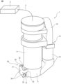
- FIG. 1 is a perspective view of a phototherapy device according to an embodiment of the invention.
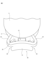
- FIG. 2 is a perspective view of the shielding part.
- FIG. 3 is a longitudinal sectional view of the distal end of the phototherapy device.
- FIG. 4 is a cross-sectional view taken along line AA in FIG. 3, and is a cross-sectional view of the distal end of the phototherapy device.
- FIG. 1 is a perspective view of a phototherapy device 1 according to an embodiment of the present invention
- FIG. 2 is a perspective view of a shielding part 20
- FIG. 3 is a longitudinal sectional view of the distal end of the phototherapy device 1.
- FIG. 4 is a cross-sectional view taken along line AA in FIG. 3, and is a cross-sectional view of the distal end portion of the phototherapy device 1.
- a phototherapy device 1 serving as a probe is electrically connected to a control device 2 via a cable 3.
- the control device 2 includes one or more processors, a storage unit, peripheral circuits thereof, and the like.
- the control device 2 comprehensively controls the overall operation of the phototherapy device 1 based on a computer program stored in advance in the storage section. During this process, the control device 2 sends control signals regarding laser irradiation and stopping, fan starting and stopping, etc., as appropriate.
- the control device 2 may have an input/output unit, for example, a display unit such as a display, or an input interface such as an operation button or a touch panel.
- the phototherapy device 1, control device 2, cable 3, input interface, etc. may be collectively referred to as a phototherapy system.
- the phototherapy device 1 has a cylindrical housing 4 and a laser light source 6 placed inside the housing 4.
- the casing 4 has a cylindrical movable part 5 that is disposed at the tip of the casing 4 and is movable in the axial direction with respect to the casing 4 .
- the casing 4 has a cylindrical shape with a circular cross section as a whole, but it may also be a cylindrical member with an elliptical cross section, or it may have another shape, for example, a square or polygonal cross section such as an octagon. It may be a cylindrical member having.
- the laser irradiated from the laser light source 6 is irradiated onto the target region through the opening 11 provided on the distal end surface of the housing 4 .
- the movable part 5 functions as a contact-type interlock mechanism in the phototherapy device 1.
- the phototherapy device 1 is configured to irradiate the laser only when the movable part 5 is pressed against the target region or the vicinity of the target region and retreats. That is, the configuration is such that the retraction of the movable part 5 is detected by a sensor disposed inside the housing 4, and the control device 2 uses the detection as a trigger to permit laser irradiation. Thereby, unintended laser irradiation can be prevented.
- the phototherapy device 1 does not need to have the movable part 5.
- An exhaust port 12 which is a first opening, is provided on the side surface of the casing 4, specifically on the side surface of the movable part 5.
- the positions of the exhaust port 12 and the intake port 13 in the housing 4 may be arbitrarily set in the axial direction and the circumferential direction.
- the phototherapy device 1 has an air supply device 14 that supplies air injected into the housing 4 from the intake port 13.
- the air supply device 14 includes a fan 15 disposed adjacent to the side surface of the housing 4 and a duct 16 that connects the fan 15 and the intake port 13. Therefore, the air F taken in by the rotation of the fan 15 is guided to the intake port 13 via the duct 16.
- the air F supplied into the casing 4 through the intake port 13 takes away heat from the inside of the casing 4 heated by laser irradiation and the target area, and then flows to the outside of the casing 4 through the exhaust port 12. is discharged to.
- the air F discharged to the outside of the casing 4 is discharged to the outside of the phototherapy device 1 via a first vent 24 and a second vent 25, which will be described later.
- the phototherapy device 1 does not need to have the air supply device 14 and the intake port 13.
- air F heated by laser irradiation inside the phototherapy device 1 is discharged to the outside of the housing 4 through the exhaust port 12 by convection.
- the exhaust ports 12 may be provided at a plurality of locations in the housing 4 in order to improve the exhaust efficiency by convection.
- the phototherapy device 1 further includes a shielding section 20 that is integrally provided with the side surface of the housing 4.
- the shielding part 20 includes a first shielding wall 21 and two second shielding walls 22 extending along the axial direction of the housing 4, and a bottom wall 23 provided flush with the tip surface of the housing 4. ing.
- the bottom wall 23 does not need to be flush with the top end surface of the casing 4 as long as it does not protrude beyond the top end surface of the casing 4 .
- the bottom wall 23 may have a bottom surface parallel to the distal end surface of the casing 4, which is disposed rearward from the distal end surface of the casing 4, and extends rearward from the edge of the distal end surface of the casing 4. It may be an inclined slope.
- the first shielding wall 21 is arranged to face the side surface of the housing 4, particularly the exhaust port 12.
- a central portion of the first shielding wall 21 in the width direction, that is, in the circumferential direction, is formed to curve convexly toward the housing 4 .
- the first shielding wall 21 is curved in the opposite direction to the side surface of the housing 4.
- Each of the two second shielding walls 22 extends radially outward from the side surface of the housing 4 with respect to the axial direction.
- the tip portions of the two second shielding walls 22 in the radial direction are continuously connected to the end portions of the first shielding wall 21 in the circumferential direction.
- a connecting portion between the first shielding wall 21 and the second shielding wall 22 is formed to curve outward in a convex shape.
- Two first ventilation holes 24 are defined by cutting out two connecting portions on the tip side between the first shielding wall 21 and the second shielding wall 22 and the corresponding bottom wall 23.
- the first shielding wall 21 and the second shielding wall 22 have an end face extending rearward along the axial direction from the distal end side of the casing 4, and an end face extending radially at a position spaced apart from the distal end of the casing 4.
- the notch is formed to form an end face extending from the top to the bottom.
- two substantially rectangular first ventilation holes 24 are defined in the shielding part 20, which are arranged on the front end side of the housing 4 and open in the circumferential direction. Note that the first ventilation hole 24 is defined so that the bottom wall 23 is not cut out, and only the two connecting portions on the tip side between the first shielding wall 21 and the second shielding wall 22 are cut out. You may also do so.
- the rear end surfaces of the first shielding wall 21 and the second shielding wall 22 and the side surface of the casing 4 define a second vent 25 that is arranged on the side surface of the casing 4 and opens rearward.
- the second ventilation port 25 has an elongated shape that extends along the circumferential direction and is narrowed at the center due to the curvature of the first shielding wall 21 .
- the two first and second ventilation holes 24 and 25 constitute a second opening that opens in the circumferential direction or rearward of the housing 4 by the first shielding wall 21 and the second shielding wall 22 and the housing 4. .
- the surface of the distal end of the phototherapy device 1 where the opening 11, which is the laser irradiation port, is in contact with the vicinity of the target region. Therefore, the laser cannot be directly viewed through the opening 11 on the distal end side of the phototherapy device 1.
- the exhaust port 12 is open to the outside of the phototherapy device 1 .
- the shielding part 20 Specifically, the position, shape, and size of the first ventilation port 24 and the second ventilation port 25 are set in relation to the position, shape, and size of the exhaust port 12.
- the optical path range of the laser is indicated by the symbol L in FIGS. 3 and 4.
- the optical path range L of the laser refers to the range of the inner space defined by the outermost contour of the irradiated laser.
- the range surrounded by the dashed line is the optical path range L of the laser.
- the line of sight V from the outside of the phototherapy device 1 through the second vent 25 is blocked by the side surface of the casing 4 around the exhaust port 12, and reaches the optical path range L of the laser.
- the line of sight V from the outside of the phototherapy device 1 through the first vent 24 is blocked by the side surface of the casing 4 around the exhaust port 12, and It will never be reached.
- the shielding part 20 is provided so that the optical path of the laser emitted from the laser light source 6 cannot be directly seen from outside the housing 4 through the exhaust port 12.
- the shielding section 20 is constructed such that when a virtual straight line connecting an arbitrary point in the optical path range L of the laser and an arbitrary point on the edge defining the exhaust port 12 is drawn, the straight line becomes the shielding section. It is formed so as to pass through 20. As a result, even if a rod-shaped insert having a light-reflecting portion is inserted into the housing 4 from the exhaust port 12 via the first vent 24 or the second vent 25, the outside of the phototherapy device 1 is The laser is never reflected.
- FIGS. 3 and 4 the reflected light R directed to the outside via the exhaust port 12 is blocked by the shielding part 20 , particularly the first shielding wall 21 . Therefore, the reflected light R cannot be visually recognized from the outside of the phototherapy device 1 via the first vent 24 or the second vent 25. That is, even if a curved insert having a light-reflecting portion is inserted into the housing 4 from the exhaust port 12 via the first vent 24 or the second vent 25, the outside of the phototherapy device 1 The laser is never reflected.
- the shielding part 20 is configured to prevent the insert from being inserted through the exhaust port 12, and to shield the reflected laser light from being irradiated to the outside even if the insert is inserted. Therefore, the phototherapy device 1 is configured so that even if the laser is unintentionally reflected inside the housing 4, the reflected light cannot be visually recognized from the outside.
- the air F discharged radially outward from the exhaust port 12 is caused by the first shielding wall 21 that is curved in the opposite direction to the side surface of the housing 4, that is, curved convexly toward the housing 4.
- the air is guided to be discharged from the first vent 24 to the outside. Furthermore, the remaining air F is discharged to the outside from the second vent 25. Since the first shielding wall 21 is curved in the opposite direction to the side surface of the housing 4, it becomes possible to guide the air F more smoothly.
- the curvature of the first shielding wall 21 may be a curvature corresponding to a part of a cylindrical surface in an axis parallel to the axis of the housing 4, or a spherical surface, as long as the air F can be guided smoothly. It may be a curve corresponding to a part of a convex curved surface such as.
- the shielding part 20 was provided integrally with the housing 4, but it may be configured separately from the housing 4. In this case, the shielding part 20 may be configured to be detachable from the housing 4.
- the phototherapy device 1 had a total of three vents, two first vents 24 and one second vent 25, but one or two of these vents It may have an opening, and it may additionally have four or more ventilation holes. The position, shape, and size of the vent may be determined based on the amount of air supplied from the intake port 13 and the like, taking into account the above-mentioned laser reflection and the like.
- the shielding portion may be provided not only for the exhaust port 12 but also for the first opening formed for other purposes.
- Phototherapy device 2 Control device 3 Cable 4 Housing 5 Movable part 6 Laser light source 11 Opening 12 Exhaust port 13 Intake port 14 Air supply device 15 Fan 16 Duct 20 Shielding portion 21 First shielding wall 22 Second shielding wall 23 Bottom wall 24 First vent 25 Second vent
Landscapes
- Health & Medical Sciences (AREA)
- Engineering & Computer Science (AREA)
- Biomedical Technology (AREA)
- Nuclear Medicine, Radiotherapy & Molecular Imaging (AREA)
- Optics & Photonics (AREA)
- Pathology (AREA)
- Physics & Mathematics (AREA)
- Radiology & Medical Imaging (AREA)
- Life Sciences & Earth Sciences (AREA)
- Animal Behavior & Ethology (AREA)
- General Health & Medical Sciences (AREA)
- Public Health (AREA)
- Veterinary Medicine (AREA)
- Radiation-Therapy Devices (AREA)
Abstract
Description
2 制御装置
3 ケーブル
4 筐体
5 可動部
6 レーザ光源
11 開口
12 排気口
13 吸気口
14 空気供給装置
15 ファン
16 ダクト
20 遮蔽部
21 第1遮蔽壁
22 第2遮蔽壁
23 底壁
24 第1通気口
25 第2通気口
Claims (6)
- 筒状の筐体と、
前記筐体の内部に配置され且つ前記筐体の先端から標的部位に対してレーザを照射するよう構成されたレーザ光源と、
前記筐体の側面に設けられた第1開口部と、
前記筐体の内部において意図せず反射するレーザの反射光であって、前記第1開口部を介して外部に向かう反射光を遮蔽するよう前記筐体の外側に設けられた遮蔽部と、を具備することを特徴とする光治療装置。 - 前記遮蔽部が、前記レーザ光源から照射されたレーザの光路を前記筐体の外部から前記第1開口部を介して直接視認できないように設けられている請求項1に記載の光治療装置。
- 前記遮蔽部が、レーザの光路範囲における任意の点と第1開口部を画成する縁部の任意の点とを結んだ仮想の直線を引いた場合に当該直線が当該遮蔽部を通過するように形成されている請求項2に記載の光治療装置。
- 前記遮蔽部が、前記筐体の軸線方向に沿って延びる遮蔽壁を有し、前記遮蔽壁と前記筐体とによって、前記筐体の周方向又は後方に開く少なくとも1つの第2開口部が形成されている請求項3に記載の光治療装置。
- 前記遮蔽壁が、前記筐体の側面に対向し、前記筐体に向かって凸状に湾曲している請求項4に記載の光治療装置。
- 前記筐体の側面に設けられた第3開口部と、前記第3開口部を介して前記筐体の内部に空気を供給する空気供給装置と、をさらに具備する請求項1乃至5のいずれか一項に記載の光治療装置。
Priority Applications (5)
| Application Number | Priority Date | Filing Date | Title |
|---|---|---|---|
| CN202380046788.7A CN119365238A (zh) | 2022-06-13 | 2023-06-12 | 光治疗装置 |
| EP23823867.9A EP4537897A4 (en) | 2022-06-13 | 2023-06-12 | PHOTOTHERAPY DEVICE |
| CA3259239A CA3259239A1 (en) | 2022-06-13 | 2023-06-12 | Phototherapy apparatus |
| KR1020247040656A KR20250007643A (ko) | 2022-06-13 | 2023-06-12 | 광 치료 장치 |
| JP2024528828A JP7802170B2 (ja) | 2022-06-13 | 2023-06-12 | 光治療装置 |
Applications Claiming Priority (2)
| Application Number | Priority Date | Filing Date | Title |
|---|---|---|---|
| JP2022-095070 | 2022-06-13 | ||
| JP2022095070 | 2022-06-13 |
Publications (1)
| Publication Number | Publication Date |
|---|---|
| WO2023243577A1 true WO2023243577A1 (ja) | 2023-12-21 |
Family
ID=89191227
Family Applications (1)
| Application Number | Title | Priority Date | Filing Date |
|---|---|---|---|
| PCT/JP2023/021654 Ceased WO2023243577A1 (ja) | 2022-06-13 | 2023-06-12 | 光治療装置 |
Country Status (6)
| Country | Link |
|---|---|
| EP (1) | EP4537897A4 (ja) |
| JP (1) | JP7802170B2 (ja) |
| KR (1) | KR20250007643A (ja) |
| CN (1) | CN119365238A (ja) |
| CA (1) | CA3259239A1 (ja) |
| WO (1) | WO2023243577A1 (ja) |
Citations (3)
| Publication number | Priority date | Publication date | Assignee | Title |
|---|---|---|---|---|
| JPS49146793U (ja) * | 1973-04-13 | 1974-12-18 | ||
| KR101865784B1 (ko) * | 2017-09-07 | 2018-06-08 | 주식회사 지티지웰니스 | 지방분해용 핸드피스의 레이저 장치와 이를 이용한 핸드피스 |
| WO2021132271A1 (ja) * | 2019-12-23 | 2021-07-01 | 帝人ファーマ株式会社 | 光治療装置 |
Family Cites Families (2)
| Publication number | Priority date | Publication date | Assignee | Title |
|---|---|---|---|---|
| KR101176851B1 (ko) * | 2010-02-01 | 2012-08-27 | 연세대학교 산학협력단 | 부항기 프로브 및 그를 구비하는 부항 장치 |
| KR102144930B1 (ko) * | 2018-03-09 | 2020-08-14 | (주)라메디텍 | 레이저 채혈기 |
-
2023
- 2023-06-12 JP JP2024528828A patent/JP7802170B2/ja active Active
- 2023-06-12 WO PCT/JP2023/021654 patent/WO2023243577A1/ja not_active Ceased
- 2023-06-12 CA CA3259239A patent/CA3259239A1/en active Pending
- 2023-06-12 EP EP23823867.9A patent/EP4537897A4/en active Pending
- 2023-06-12 CN CN202380046788.7A patent/CN119365238A/zh active Pending
- 2023-06-12 KR KR1020247040656A patent/KR20250007643A/ko active Pending
Patent Citations (3)
| Publication number | Priority date | Publication date | Assignee | Title |
|---|---|---|---|---|
| JPS49146793U (ja) * | 1973-04-13 | 1974-12-18 | ||
| KR101865784B1 (ko) * | 2017-09-07 | 2018-06-08 | 주식회사 지티지웰니스 | 지방분해용 핸드피스의 레이저 장치와 이를 이용한 핸드피스 |
| WO2021132271A1 (ja) * | 2019-12-23 | 2021-07-01 | 帝人ファーマ株式会社 | 光治療装置 |
Non-Patent Citations (1)
| Title |
|---|
| See also references of EP4537897A4 * |
Also Published As
| Publication number | Publication date |
|---|---|
| EP4537897A1 (en) | 2025-04-16 |
| CN119365238A (zh) | 2025-01-24 |
| JP7802170B2 (ja) | 2026-01-19 |
| KR20250007643A (ko) | 2025-01-14 |
| CA3259239A1 (en) | 2025-04-02 |
| EP4537897A4 (en) | 2026-04-08 |
| JPWO2023243577A1 (ja) | 2023-12-21 |
Similar Documents
| Publication | Publication Date | Title |
|---|---|---|
| US10564411B2 (en) | Illumination device and endoscope | |
| JP6871231B2 (ja) | 一体型照明システムを備えた硝子体カッタ | |
| JP2026063019A (ja) | レーザー治療を制御するためのシステムおよび方法 | |
| JP5886866B2 (ja) | 共通の光源を使用する光コヒーレンストモグラフィ及び照明 | |
| US20200155233A1 (en) | Fiber optic laser surgical instrument having a radial dispersion pattern | |
| JP7123978B2 (ja) | 位置決め装置、システム及び方法 | |
| JP7725504B2 (ja) | パーソナルケアデバイスのための向上された冷却 | |
| CN113950353A (zh) | 光治疗诊断装置及其工作方法 | |
| WO2020105096A1 (ja) | 内視鏡フードおよび内視鏡システム | |
| EP3975952B1 (en) | Aligning multi-wavelength laser beams with cores of a multi-core fiber | |
| WO2023243577A1 (ja) | 光治療装置 | |
| US10018784B2 (en) | Fiber-optic device and process for manufacturing the device | |
| JP4804534B2 (ja) | 電磁放射線供給機器 | |
| WO2020115843A1 (ja) | 光照射処置具 | |
| JP7210377B2 (ja) | 医療用レーザライトガイド | |
| KR102730593B1 (ko) | 광 조사 장치 | |
| CN116997285A (zh) | 照射探针系统以及照射探针 | |
| JP7618216B2 (ja) | 光照射装置 | |
| JPS6251633B2 (ja) | ||
| KR20210119967A (ko) | 광 프로브 | |
| WO2019130465A1 (ja) | 外科処置装置 | |
| JPH01262855A (ja) | レーザプローブ |
Legal Events
| Date | Code | Title | Description |
|---|---|---|---|
| 121 | Ep: the epo has been informed by wipo that ep was designated in this application |
Ref document number: 23823867 Country of ref document: EP Kind code of ref document: A1 |
|
| WWE | Wipo information: entry into national phase |
Ref document number: 2024528828 Country of ref document: JP |
|
| ENP | Entry into the national phase |
Ref document number: 20247040656 Country of ref document: KR Kind code of ref document: A |
|
| WWE | Wipo information: entry into national phase |
Ref document number: 1020247040656 Country of ref document: KR |
|
| WWE | Wipo information: entry into national phase |
Ref document number: 202380046788.7 Country of ref document: CN |
|
| WWE | Wipo information: entry into national phase |
Ref document number: 2023823867 Country of ref document: EP |
|
| NENP | Non-entry into the national phase |
Ref country code: DE |
|
| WWP | Wipo information: published in national office |
Ref document number: 202380046788.7 Country of ref document: CN |
|
| ENP | Entry into the national phase |
Ref document number: 2023823867 Country of ref document: EP Effective date: 20250113 |
|
| WWP | Wipo information: published in national office |
Ref document number: 2023823867 Country of ref document: EP |