WO2023248580A1 - Dispositif de génération de potentiel vectoriel, procédé d'agencement de bobines à potentiel vectoriel, transformateur à potentiel vectoriel et système d'alimentation électrique sans contact - Google Patents
Dispositif de génération de potentiel vectoriel, procédé d'agencement de bobines à potentiel vectoriel, transformateur à potentiel vectoriel et système d'alimentation électrique sans contact Download PDFInfo
- Publication number
- WO2023248580A1 WO2023248580A1 PCT/JP2023/014505 JP2023014505W WO2023248580A1 WO 2023248580 A1 WO2023248580 A1 WO 2023248580A1 JP 2023014505 W JP2023014505 W JP 2023014505W WO 2023248580 A1 WO2023248580 A1 WO 2023248580A1
- Authority
- WO
- WIPO (PCT)
- Prior art keywords
- vector potential
- coil
- coils
- vector
- solenoid
- Prior art date
- Legal status (The legal status is an assumption and is not a legal conclusion. Google has not performed a legal analysis and makes no representation as to the accuracy of the status listed.)
- Ceased
Links
Images





Classifications
-
- A—HUMAN NECESSITIES
- A61—MEDICAL OR VETERINARY SCIENCE; HYGIENE
- A61N—ELECTROTHERAPY; MAGNETOTHERAPY; RADIATION THERAPY; ULTRASOUND THERAPY
- A61N2/00—Magnetotherapy
- A61N2/02—Magnetotherapy using magnetic fields produced by coils, including single turn loops or electromagnets
-
- H—ELECTRICITY
- H01—ELECTRIC ELEMENTS
- H01F—MAGNETS; INDUCTANCES; TRANSFORMERS; SELECTION OF MATERIALS FOR THEIR MAGNETIC PROPERTIES
- H01F38/00—Adaptations of transformers or inductances for specific applications or functions
- H01F38/14—Inductive couplings
-
- H—ELECTRICITY
- H01—ELECTRIC ELEMENTS
- H01F—MAGNETS; INDUCTANCES; TRANSFORMERS; SELECTION OF MATERIALS FOR THEIR MAGNETIC PROPERTIES
- H01F5/00—Coils
-
- H—ELECTRICITY
- H01—ELECTRIC ELEMENTS
- H01F—MAGNETS; INDUCTANCES; TRANSFORMERS; SELECTION OF MATERIALS FOR THEIR MAGNETIC PROPERTIES
- H01F3/00—Cores, Yokes, or armatures
- H01F3/10—Composite arrangements of magnetic circuits
- H01F3/14—Constrictions; Gaps, e.g. air-gaps
Definitions
- the present invention relates to a vector potential generator, a vector potential coil arrangement method, a vector potential transformer, and a contactless power supply system.
- the return current conductor connected in series with the vector potential coil allows the internal region of the vector potential coil (the hollow region formed by the windings of the solenoid coil, that is, the windings of the coil shaft) to be substantially free of magnetic field.
- a vector potential generation device that generates a state has also been developed (see, for example, Patent Document 2).
- a vector potential detection device has also been developed that detects a vector potential by utilizing the fact that a voltage is induced by a vector potential that changes over time (see, for example, Patent Document 3).
- the vector potential coil described above revolves more than once, and the object to which the generated vector potential is applied with good strength (for example, the secondary conductor) is placed in the internal region of the approximately annular vector potential coil. Therefore, the objects to which the vector potential is applied are limited to those that can be inserted into the internal region of the vector potential coil.
- the present invention has been made in view of the above-mentioned problems, and provides a vector potential generator and a vector potential coil arrangement method with fewer restrictions on objects to which vector potential is applied, as well as a vector potential transformer that can utilize the vector potential generator. , and to obtain a contactless power supply system.
- a vector potential generator includes a vector potential coil that is a solenoid coil extending along a curved coil axis, a ferromagnetic member extending along the coil axis within the solenoid coil, and a current flowing through the vector potential coil. and a power supply device that conducts.
- the vector potential coil and the ferromagnetic member each have an opening in the circumferential direction.
- a method for arranging a vector potential coil uses a vector potential coil, which is a solenoid coil extending along a curved coil axis, and a support body that supports a ferromagnetic member extending along the coil axis within the solenoid coil.
- a vector potential coil and a ferromagnetic member are arranged at a position where a vector potential is generated in the brain of a human body without attaching the support to the head.
- a vector potential generation device includes a plurality of vector potential coils that are solenoid coils extending along the respective coil axes, and a power supply device that conducts current to the plurality of vector potential coils.
- the plurality of vector potential coils are arranged along a linear or curved arrangement direction.
- a method for arranging vector potential coils according to the present invention involves attaching a support to the head of a human body that supports a plurality of vector potential coils, which are plural solenoid coils extending along the respective coil axes. Instead, multiple vector potential coils are placed at positions that generate vector potential in the human brain.
- a contactless power supply system includes any of the vector potential generation devices described above and a power receiving side device. Then, the power receiving side device senses the vector potential generated by the vector potential generator, and connects a secondary conductor member in which a secondary voltage is induced by the vector potential, and a power source that supplies the power obtained from the secondary voltage to the load. A circuit.
- a vector potential transformer includes a vector potential coil that is a solenoid coil extending along a curved coil axis, a ferromagnetic member extending along the coil axis within the solenoid coil, and sensing the vector potential. , and a secondary conductor member in which a secondary voltage is induced by the vector potential.
- the vector potential coil and the ferromagnetic member each have an opening in the circumferential direction.
- the vector potential transformer senses a plurality of vector potential coils which are a plurality of solenoid coils extending along the respective coil axes, and a vector potential generated by the plurality of vector potential coils, and uses the vector potential to generate two and a secondary conductor member in which a secondary voltage is induced.
- the plurality of vector potential coils are arranged along a linear or curved arrangement direction.
- a vector potential generation device and a vector potential coil arrangement method with fewer restrictions on objects to which vector potential is applied, as well as a vector potential transformer and a contactless power supply system that can utilize the vector potential generation device.
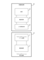
- FIG. 1 is a block diagram showing the configuration of a vector potential generation device 10 according to an embodiment of the present invention.
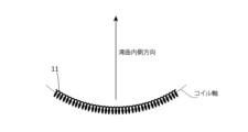
- FIG. 2 is a diagram showing an example of a vector potential coil in the vector potential coil device 1 shown in FIG. 1.
- FIG. 3 is a diagram showing an example of the vector potential coil device 1 in the first embodiment.
- FIG. 4 is a diagram showing an example of application of a vector potential by the vector potential generator 10 according to the first embodiment.
- FIG. 5 is a block diagram showing the configuration of a contactless power supply system according to Embodiment 2 of the present invention.
- FIG. 6 is a diagram showing an example of the vector potential coil device 1 and the secondary conductor member 21 in the non-contact power supply system shown in FIG. FIG.
- FIG. 7 is a diagram showing the configuration of the vector potential coil device 1 in the vector potential generation device 10 according to Embodiment 4 of the present invention.
- FIG. 8 is a diagram showing the configuration of the vector potential coil device 1 in the vector potential generation device 10 according to Embodiment 5 of the present invention.
- FIG. 9 is a diagram showing the configuration of the vector potential coil device 1 in the vector potential generation device 10 according to Embodiment 6 of the present invention.
- FIG. 10 is a diagram showing the configuration of vector potential coil device 1 in vector potential generation device 10 according to Embodiment 7 of the present invention.
- FIG. 11 is a diagram showing an example of a bed incorporating the vector potential generation device 10 according to the seventh embodiment.
- FIG. 12 is a diagram showing the configuration of the vector potential coil device 1 in the vector potential generation device 10 according to Embodiment 8 of the present invention.
- FIG. 13 is a diagram showing the configuration of the vector potential coil device 1 in the vector potential generation device 10 according to Embodiment 9 of the present invention.
- FIG. 14 is a front view showing an example of a vector potential coil in the vector potential coil device 1 according to Embodiment 10 of the present invention.
- FIG. 15 is a top view showing an example of the vector potential coil in the vector potential coil device 1 according to Embodiment 10 of the present invention.
- FIG. 16 is a side view showing an example of a vector potential coil in the vector potential coil device 1 according to Embodiment 10 of the present invention.
- FIG. 1 is a block diagram showing the configuration of a vector potential generation device 10 according to an embodiment of the present invention.
- a vector potential generation device 10 shown in FIG. 1 includes a vector potential coil device 1 and a power supply device 2.
- FIG. 2 is a diagram showing an example of a vector potential coil in the vector potential coil device 1 shown in FIG. 1.
- the vector potential coil device 1 includes a vector potential coil (hereinafter also referred to as VP coil) 11 as shown in FIG. 2, for example.
- the VP coil 11 is a solenoid coil extending along a curved coil axis.
- FIG. 3 is a diagram showing an example of the vector potential coil device 1 in the first embodiment.
- the vector potential coil device 1 includes the above-mentioned VP coil 11 and a ferromagnetic member 11A.
- the ferromagnetic member 11A has a shape extending along the above-described coil axis within the above-described solenoid coil, and is made of a ferromagnetic material.
- the vector potential due to the current flowing through the VP coil 11 becomes weaker as it moves away from the current, but since the VP coil 11 and the ferromagnetic member 11A are curved as described above, At the center of curvature), the vector potentials generated by the currents at each position of the VP coil 11 overlap, so the strength increases. Further, since the vector potential is enhanced according to the effective permeability of the ferromagnetic member 11, the strength of the vector potential becomes larger in the inner direction of the curve (in the case of an arc shape, the center of curvature).
- the power supply device 2 shown in FIG. 1 generates a current based on power from a commercial power source or a battery (primary battery or secondary battery), and transfers the current (here, an alternating current of a predetermined frequency) to a VP coil 11. Make it conductive. Note that when the power supply device 2 conducts current to the VP coil 11 using battery power, the vector potential generation device 10 may be a portable device that includes the battery.
- the VP coil 11 and the ferromagnetic member 11A are provided with an opening 14 in the circumferential direction.
- the coil axis of the VP coil 11 has not been rotated more than once.
- the above-mentioned coil axis has a circular arc shape
- the angle (center angle) from one end of the VP coil 11 (coil axis) to the other end as seen from the center of the circle that includes the coil axis is:
- the angle (center angle) from one end of the ferromagnetic member 11A to the other end as seen from the center of the circle including the coil axis is less than 360 degrees.
- an opening 14 is formed.
- the central angle may be 180 degrees or less than 180 degrees.
- the larger the central angle the greater the strength of the vector potential in the direction toward the inside of the curve, so it is preferable that the central angle is large.
- This central angle is any angle greater than 0 degrees and less than 360 degrees; furthermore, (a) it may be any angle greater than 0 degrees and less than 180 degrees, and (b) greater than 0 degrees. (c) may be any angle greater than 0 degrees and less than 45 degrees; or (d) greater than 0.5 degrees and less than 360 degrees. Furthermore, (e) it may be any angle between 0.5 degrees and 180 degrees, and (f) 0.5 degrees and above and 90 degrees or less. (e) Any angle between 0.5 degrees and 45 degrees; (f) Any angle between 0.5 degrees and 25 degrees. or (g) any angle greater than or equal to 2 degrees and less than 360 degrees; and (h) any angle greater than or equal to 2 degrees and less than 180 degrees.
- the opening 14 be larger (in other words, depending on the shape and size of the object to be applied, the above-mentioned coil axis the radius of curvature and/or the central angle described above is determined).
- FIG. 4 is a diagram showing an example of application of a vector potential by the vector potential generation device 10 according to the first embodiment.
- an object to which a vector potential is applied in FIG. 4, a human foot 101 is placed in this opening 14.
- the ferromagnetic member 11A is made of a conductive material such as permalloy, and one end of the VP coil 11 and one end (end portion 11A1) of the ferromagnetic member 11A are mutually connected. It is electrically connected and serves as a path for current. Then, the power supply device 2 applies a voltage to the other end of the VP coil 11 and the other end of the ferromagnetic member 11A to cause the VP coil 11 to conduct current.
- the power supply device 2 applies voltage to a terminal 12 electrically connected to the other end of the VP coil 11 and a terminal 13 electrically connected to the other end (end 11A2) of the ferromagnetic member 11A. The voltage is applied to cause the VP coil 11 to conduct current.
- the coil axis of the VP coil 11 does not revolve more than once, the distance between both ends of the VP coil 11 becomes large, but the ferromagnetic member 11A is used as a current path, and either one of the VP coils 11 Since the two terminals 12 and 13 are arranged on the end side, the area surrounded by the path flowing through the wiring from the power supply device 2 to the VP coil 11 and the ferromagnetic member 11A is relatively narrow, and the current flowing through this wiring is Unnecessary magnetic fields generated due to this are suppressed.
- the power supply device 2 applies a predetermined voltage to the above-mentioned terminals 12 and 13 in the vector potential generation device 10 to conduct current to the VP coil 11 and the ferromagnetic member 11A.
- a magnetic field is generated along the coil axis by the current flowing through the VP coil 11, and a vector potential is generated parallel to the current. is larger than the vector potential of the VP coil 11 in the direction toward the outside of the curve.
- the VP coil 11 is a solenoid coil that extends along the curved coil axis, and the ferromagnetic member 11A extends along the coil axis within the solenoid coil. It is extending.
- the power supply device 2 causes the VP coil 11 to conduct current.
- the VP coil 11 and the ferromagnetic member 11A are provided with an opening 14 in the circumferential direction (that is, the circumferential direction of the VP coil 11 and the ferromagnetic member 11A that are rotating less than one turn).
- the object to which the vector potential is applied can be placed in the opening 14 or in the internal region of the VP coil 11 via the opening 14, so there are fewer restrictions on the object to which the vector potential is applied.
- a circular VP coil when it is desired to apply a vector potential to the shoulders of a human body, using a circular VP coil requires a relatively large VP coil that allows the human body's torso to fit into the hollow part.
- a vector potential can be effectively applied to such a location using a relatively small VP coil 11.
- FIG. 5 is a block diagram showing the configuration of a contactless power supply system according to Embodiment 2 of the present invention.
- the contactless power supply system according to the second embodiment includes the above-described vector potential generation device 10 and a power receiving device 30.
- the power receiving device 30 includes a secondary conductor member 21 to which a vector potential is applied, a power supply circuit 22, and a load 23.
- the secondary conductor member 21 senses the vector potential generated by the alternating current by the vector potential generator 10, and generates a secondary voltage (alternating current voltage) based on the time change of the vector potential as shown in Patent Document 3 mentioned above. induced.
- FIG. 6 is a diagram showing an example of the vector potential coil device 1 and the secondary conductor member 21 in the non-contact power supply system shown in FIG. 5.
- the secondary conductor member 21 is preferably arranged at the center of curvature of the coil axis of the VP coil 11.
- the power supply circuit 22 is connected to the terminals 21A and 21B of the secondary conductor member 21, and supplies the load 23 with power obtained from the voltage generated between the terminals 21A and 21B (that is, the above-mentioned secondary voltage).
- the power supply circuit 22 includes, for example, a rectifying and smoothing circuit, converts the power obtained from the secondary voltage into DC power, and supplies the DC power to the load 23 .
- the vector potential generator 10 generates a relatively strong vector potential in the secondary conductor member 21 of the power receiving device 30 disposed in or around the opening 14 . As a result, a secondary voltage is generated in the secondary conductor member 21.
- the power supply circuit 22 supplies power based on this secondary voltage to the load 23.
- the secondary conductor member 21 senses the vector potential generated by the vector potential generator 10, and a secondary voltage is induced by the vector potential.
- the power supply circuit 22 supplies power obtained from the secondary voltage to the load 23.
- the vector potential transformer according to Embodiment 3 of the present invention includes the above-mentioned VP coil 11, the above-mentioned ferromagnetic member 11A, and the above-mentioned secondary conductor member 21. Thereby, power is transmitted from the VP coil 11 (that is, the primary side) to the secondary conductor member 21 (that is, the secondary side).
- This vector potential transformer is one device including a VP coil 11, a ferromagnetic member 11A, and a secondary conductor member 21, and the relationship between the VP coil 11, the ferromagnetic member 11A, and the secondary conductor member 21 is The positional relationship is fixed.
- the number of VP coils 11 used in the vector potential transformer according to the third embodiment may be one or more, and the VP coils 11 of any of the other embodiments may be used as appropriate.
- FIG. 7 is a diagram showing the configuration of the vector potential coil device 1 in the vector potential generation device 10 according to Embodiment 4 of the present invention.
- a ferromagnetic member 11B is arranged inside the VP coil 11 (that is, the solenoid coil). Like the ferromagnetic member 11A, this ferromagnetic member 11B has a shape along the coil axis of the VP coil 11, and further extends to the outside of the VP coil 11 (in the direction of the outside of the curve) to form a closed magnetic path. are doing.
- the ferromagnetic member 11B is a member made of a conductive ferromagnetic material (for example, a metal magnetic material such as permalloy), and connects the connection point 11B1 on one coil end side of the VP coil 11 and the other coil of the VP coil 11.
- One coil end of the VP coil 11 is electrically connected to the ferromagnetic member 11B at the connection point 11B1.
- the other coil end of the VP coil 11 is electrically connected to the terminal 12, the connection point 11B2 of the ferromagnetic member 11B is electrically connected to the terminal 13 via the lead wire, and the power supply device 2 , a voltage is applied to the terminals 12 and 13 to cause the VP coil 11 to conduct current.
- a gap 11B3 is formed in the ferromagnetic member 11B in the direction toward the outside of the curve of the VP coil 11, and the gap 11B3 allows current to pass through the portion of the ferromagnetic member 11B outside the curve of the VP coil 11. It is no longer conductive.
- the transition part between the inner part and the outer part of the ferromagnetic member 11B is made continuous and smooth without sharp bends in order to reduce the influence of leakage of magnetic flux and decrease in magnetic permeability due to bending. It is preferable to have a curved shape. Further, the ferromagnetic member 11B may be formed by connecting a plurality of members.
- vector potential coil device 1 in the vector potential generator 10 according to the fourth embodiment is applicable to any of the first to third embodiments.
- FIG. 8 is a diagram showing the configuration of the vector potential coil device 1 in the vector potential generation device 10 according to Embodiment 5 of the present invention.
- the VP coil 11 includes an inner solenoid coil 11-1 and an outer solenoid coil 11-2 that extend along the same curved coil axis and have different coil diameters. , one coil end of the inner solenoid coil 11-1 and one coil end of the outer solenoid coil 11-2 are electrically connected.
- the inner solenoid coil 11-1 and the outer solenoid coil 11-2 each function as one VP coil. Therefore, the VP coil 11 of the fifth embodiment electrically functions as two VP coils. The configuration is such that they are connected in series in the same phase.
- a ferromagnetic member 11C is arranged inside the VP coil 11 (inner solenoid coil 11-1).
- This ferromagnetic member 11C is similar to the above-described ferromagnetic member 11A.
- the VP coil 11 and the ferromagnetic member 11C are not electrically connected, and the ferromagnetic member 11C does not need to have electrical conductivity.
- the power supply device 2 applies a voltage to the other end of the inner solenoid coil 11-1 and the other end 11-2 of the outer solenoid coil to conduct current to the VP coil 11. Specifically, the power supply device 2 applies voltage to a terminal 12 electrically connected to the other end of the inner solenoid coil 11-1 and a terminal 13 electrically connected to the other end 11-2 of the outer solenoid coil. The voltage is applied to cause the VP coil 11 to conduct current.
- vector potential coil device 1 in the vector potential generator 10 according to the fifth embodiment is applicable to any of the first to third embodiments.
- FIG. 9 is a diagram showing the configuration of the vector potential coil device 1 in the vector potential generation device 10 according to Embodiment 6 of the present invention.
- the VP coil 11 includes an inner solenoid coil 11-1 and an outer solenoid coil 11-2 similar to those in the fifth embodiment. Furthermore, in the sixth embodiment, as shown in FIG. 9, for example, a ferromagnetic member 11D is arranged inside the VP coil 11 (inner solenoid coil 11-1). This ferromagnetic member 11D is similar to the above-described ferromagnetic member 11B. However, the VP coil 11 and the ferromagnetic member 11D are not electrically connected, the ferromagnetic member 11D does not need to have electrical conductivity, and no gap is provided.
- the alternating current conducts through the inner solenoid coil 11-1 and the outer solenoid coil 11-2, but does not conduct through the ferromagnetic member 11D, so the ferromagnetic member 11D requires conductivity and a gap. I don't.
- FIG. 10 is a diagram showing the configuration of the vector potential coil device 1 in the vector potential generation device 10 according to Embodiment 7 of the present invention.
- the vector potential coil device 1 includes a plurality of VP coils 11.
- Each VP coil 11 in the seventh embodiment is a plurality of solenoid coils that have a linear coil axis and extend along the coil axis.
- the plurality of VP coils 11 are arranged along a linear arrangement direction. In other words, the vector potential coil device 1 has a substantially flat outer shape.
- the power supply device 2 conducts current through the plurality of VP coils 11 .
- the plurality of VP coils 11 may be electrically connected in series or in parallel. Further, a plurality of power supply devices 2 may conduct current to a plurality of VP coils 11, respectively.
- the plurality of power supply devices 2 respectively conduct the alternating currents to the plurality of VP coils 11 so that the alternating currents conducted to the plurality of VP coils 11 are synchronized.
- the vector potential coil device 1 includes a plurality of ferromagnetic members (not shown) extending along the coil axes of the plurality of VP coils 11, similar to the ferromagnetic members described above.
- FIG. 11 is a diagram showing an example of a bed incorporating the vector potential generation device 10 according to the seventh embodiment.
- the plurality of VP coils 11 described above are built into the mattress 211 of the bed 201, and the power supply device 2 is installed in the main body of the bed 201 or the like.
- a vector potential is applied to the person sleeping on the bed 201.
- the VP coil 11 is arranged along a direction perpendicular to the longitudinal direction of the bed 201 (the longitudinal direction of the human body), but the VP coil 11 is arranged along the longitudinal direction of the bed 201 (the longitudinal direction of the human body).
- a coil 11 may be arranged.
- the VP coil 11 is built in the mattress 211, but the VP coil 11 may be built in the bed body, a pad placed on the mattress 211, or the like.
- FIG. 12 is a diagram showing the configuration of the vector potential coil device 1 in the vector potential generation device 10 according to Embodiment 8 of the present invention.
- the vector potential coil device 1 includes a plurality of VP coils 11.
- Each VP coil 11 in Embodiment 8 is a plurality of solenoid coils that have a linear coil axis and extend along the coil axis.
- the plurality of VP coils 11 are arranged along a curved (curved) arrangement direction.
- the power supply device 2 conducts current through the plurality of VP coils 11 .
- the plurality of VP coils 11 may be electrically connected in series or in parallel.
- the vector potential coil device 1 also includes a plurality of ferromagnetic members (not shown) extending along the coil axes of the plurality of VP coils 11, similar to the ferromagnetic members described above.
- the arrangement direction is a closed curve
- the plurality of VP coils 11 are arranged along the arc-shaped arrangement direction.
- the plurality of VP coils 11 are arranged within a predetermined center angle ⁇ range (here, at equal angular intervals) with respect to a circle including an arc in the arrangement direction. Since the vector potentials of the two VP coils 11 are canceled at an intermediate position between the two VP coils 11, the central angle ⁇ is set to any angle less than 180 degrees, for example.
- a part of the human body such as an arm or a leg is placed in the space inward of the plurality of VP coils 11 arranged, and a vector potential is applied to that part.
- a plurality of VP coils 11 having linear coil axes are arranged along a curved arrangement direction along a predetermined plane of symmetry (perpendicular to the X axis and parallel to the Z and Y axes).
- a plane of symmetry perpendicular to the X axis and parallel to the Z and Y axes.
- the vector combination of vector potentials generated by the plurality of VP coils 11 As a result, a vector potential is generated in a direction perpendicular to the symmetry plane (X-axis direction in FIG. 12). Therefore, for example, the VP coil 11 has a curved coil axis as shown in FIG.
- the VP coil 11 has a linear coil axis, and is arranged symmetrically with respect to a predetermined plane of symmetry along a curved arrangement direction.
- a vector potential can be generated in a desired direction within a two-dimensional plane of the X-axis and the Y-axis.
- FIG. 13 is a diagram showing the configuration of the vector potential coil device 1 in the vector potential generation device 10 according to Embodiment 9 of the present invention.
- the vector potential coil device 1 includes a plurality of VP coils 11.
- the plurality of VP coils 11 are each wound along a linear coil axis, and are wound so that the inclination angle of the winding direction gradually changes along the direction of the coil axis.
- the vector potential coil device 1 also includes a plurality of ferromagnetic members (not shown) extending along the coil axes of the plurality of VP coils 11, similar to the ferromagnetic members described above.
- the VP coil 11 is wound along a linear coil axis, but the inclination angle of the winding direction (coil It is wound so that the angle (angle between the axial direction and the winding direction) A0 to A5 gradually changes.
- the tilt angle at the center of the VP coil 11 is 90 degrees, and the farther from the center, the smaller the tilt angle becomes (A0>A1>A2>A3>A4>A5).
- FIG. 14 is a front view showing an example of a vector potential coil in the vector potential coil device 1 according to Embodiment 10 of the present invention.
- FIG. 15 is a top view showing an example of the vector potential coil in the vector potential coil device 1 according to Embodiment 10 of the present invention.
- FIG. 16 is a side view showing an example of a vector potential coil in the vector potential coil device 1 according to Embodiment 10 of the present invention.
- the vector potential coil device 1 includes a plurality of vector potential coils 31-1 to 31-5.
- the plurality of vector potential coils 31-1 to 31-5 are each wound along a curved coil axis, and are wound in the curved inner direction of the coil axis (in other words, The planes (including the coil axis) intersect with each other.
- FIG. 14 to 16 the plurality of vector potential coils 31-1 to 31-5 are each wound along a curved coil axis, and are wound in the curved inner direction of the coil axis (in other words, The planes (including the coil axis) intersect with each other.
- the planes including the coil axes of the plurality of vector potential coils 31-1 to 31-5 are parallel to the Y-axis direction, and the inclination angle of these planes with respect to the X-axis direction is A plurality of vector potential coils 31-1 to 31-5 are arranged so that the angular intervals of the vector potential coils 31-1 to 31-5 are approximately the same. Further, here, the inclination angle of the vector potential coil 31-1 is 90 degrees.
- the vector potential coil device 1 is equipped with five vector potential coils 31-1 to 31-5, but similar vector potential coils of any number M of 2 to 4 or 6 or more It may also include potentials 31-1 to 31-M.
- the shape (curvature, etc.) and arrangement of the coil axes are determined so that the coil axes of the plurality of vector potential coils 31-1 to 31-5 are included in a single partial spherical surface (for example, a hemispherical surface), and that portion The application target is placed at the center of the spherical surface (that is, the center of curvature of all the coil axes).
- the shape (curvature, etc.) and arrangement of the coil axes are adjusted so that the coil axes of the plurality of vector potential coils 31-1 to 31-5 are included in a single curved surface other than a partial spherical surface (partial aspheric surface). It may be decided.
- the plurality of vector potential coils 31-1 to 31-5 each generate a vector potential according to an alternating current in the same manner as in the above-described embodiment, and the plurality of vector potential coils 31-1 to 31-5 generate Vector potentials are combined to obtain vector potential VP(t).
- the power supply device 2 conducts alternating current to the plurality of vector potential coils 31-1 to 31-5 so that the amplitude of the combined vector potential VP(t) is maximized (for example, in phase with each other).
- any of the above-mentioned ferromagnetic members may be arranged along the coil axes of the plurality of vector potential coils 31-1 to 31-5, respectively.
- the vector potential generation device 10 As described above, according to the vector potential generation device 10 according to the tenth embodiment, the vector potential is concentrated in the curved inner direction of the plurality of vector potential coils 31-1 to 31-5, and a high-strength vector potential is generated. can be applied to the application target.
- the vector potential coil device 1 is placed on the head of a human body in order to treat brain tumors (such as glioblastoma) in the human body.
- brain tumors such as glioblastoma
- the vector potential generation device 10 further includes a support body shaped to match the shape of the head of a human body, and one of the vector potential coil devices 1 (VP coils) described above is attached to the support body. and a ferromagnetic material member, a plurality of VP coils, etc.) are fixed.
- a helmet worn on the head, a stand on which a VP coil or the like is placed near the head, etc. are used.
- the support described above may be a device that receives contact with the head, such as a pillow or a headrest of a chair, in which case the vector potential coil device 1 described above is built into such a support.
- the vector potential coil device 1 is placed close to a position where a vector potential is generated in the human brain. That is, by conducting an alternating current to the vector potential coil device 1, an alternating vector potential is generated in the brain inside the head. This applies an alternating electric field or alternating current to the brain.
- an alternating current electric field under such conditions is non-invasively applied to the brain by the vector potential coil device 1.
- an electrode pad is usually pasted on the skin of the head after shaving, but according to the eleventh embodiment, shaving is not necessary. In addition, it becomes unnecessary to apply adhesive electrode pads to the skin of the head, and the burden (physical burden and mental burden) on the patient during treatment by applying an alternating electric field is reduced.
- This eddy current is a current that flows in a direction that cancels out changes in the magnetic field explained by Faraday's electromagnetic induction and Lenz's law, so the eddy current that flows in the area near the epidermis of the cerebrum cancels out the initial pulsed magnetic field. , were unable to induce currents deep in the brain.
- the surface of the cerebrum has a wrinkled structure, and even if the wrinkles are adjacent to each other, the valleys between the wrinkles are deep. Electrically, the electrical resistance between the wrinkles is high, so a pulsed magnetic field can control the current It is difficult to flush the area.
- the magnetic flux of the pulsed magnetic field is applied from a direction perpendicular to the scalp, eddy currents can only flow in a plane parallel to the scalp.
- the two conventional methods have the above-mentioned problems, but since the device of this embodiment generates a vector potential, it can be applied to the skull even in deep parts of the brain such as the cerebellum, corpus callosum, and hypothalamus. Electric fields can be applied without interference.
- the ferromagnetic member arranged along the coil axis of the VP coil 11 may be omitted if necessary.
- power is transmitted from the vector potential generator 10 to the secondary conductor member 21, but in addition, power is transmitted from the vector potential generator 10 to the secondary conductor member 21.
- an alternating current for example, regenerative current
- the VP coil 11 has a two-layer structure in the radial direction of the inner solenoid coil 11-1 and the outer solenoid coil 11-2, but if the number of layers is even , the number of layers may be four or more. In that case, either end of the solenoid coil 11-i is connected to the solenoid coil 11-(i+1) of the next layer so that the solenoid coils 11-i of all layers are electrically connected in series.
- the present invention is applicable, for example, to generation of vector potential using a VP coil.
Landscapes
- Engineering & Computer Science (AREA)
- Power Engineering (AREA)
- Health & Medical Sciences (AREA)
- Biomedical Technology (AREA)
- Nuclear Medicine, Radiotherapy & Molecular Imaging (AREA)
- Radiology & Medical Imaging (AREA)
- Life Sciences & Earth Sciences (AREA)
- Animal Behavior & Ethology (AREA)
- General Health & Medical Sciences (AREA)
- Public Health (AREA)
- Veterinary Medicine (AREA)
- Magnetic Treatment Devices (AREA)
- Coils Of Transformers For General Uses (AREA)
Abstract
Priority Applications (2)
| Application Number | Priority Date | Filing Date | Title |
|---|---|---|---|
| DE112023001438.8T DE112023001438T5 (de) | 2022-06-23 | 2023-04-10 | Vorrichtung zur erzeugung eines vektorpotentials, verfahren zur anordnung einer vektorpotentialspule, vektorpotential-transformator und kontaktloses stromversorgungssystem |
| CN202380026844.0A CN118872007A (zh) | 2022-06-23 | 2023-04-10 | 向量势产生装置、向量势线圈配置方法、向量势变压器以及非接触馈电系统 |
Applications Claiming Priority (2)
| Application Number | Priority Date | Filing Date | Title |
|---|---|---|---|
| JP2022-100853 | 2022-06-23 | ||
| JP2022100853A JP7841705B2 (ja) | 2022-06-23 | 2022-06-23 | ベクトルポテンシャル発生装置、ベクトルポテンシャルコイル配置方法、ベクトルポテンシャルトランス、および非接触給電システム |
Publications (1)
| Publication Number | Publication Date |
|---|---|
| WO2023248580A1 true WO2023248580A1 (fr) | 2023-12-28 |
Family
ID=89379451
Family Applications (1)
| Application Number | Title | Priority Date | Filing Date |
|---|---|---|---|
| PCT/JP2023/014505 Ceased WO2023248580A1 (fr) | 2022-06-23 | 2023-04-10 | Dispositif de génération de potentiel vectoriel, procédé d'agencement de bobines à potentiel vectoriel, transformateur à potentiel vectoriel et système d'alimentation électrique sans contact |
Country Status (4)
| Country | Link |
|---|---|
| JP (1) | JP7841705B2 (fr) |
| CN (1) | CN118872007A (fr) |
| DE (1) | DE112023001438T5 (fr) |
| WO (1) | WO2023248580A1 (fr) |
Cited By (1)
| Publication number | Priority date | Publication date | Assignee | Title |
|---|---|---|---|---|
| WO2025191907A1 (fr) * | 2024-03-11 | 2025-09-18 | スミダコーポレーション株式会社 | Système de dispositif implantable |
Citations (10)
| Publication number | Priority date | Publication date | Assignee | Title |
|---|---|---|---|---|
| JPH10151467A (ja) * | 1996-08-30 | 1998-06-09 | Toshihiko Yayama | 液体の活性化処理方法 |
| US20140239954A1 (en) * | 2011-08-01 | 2014-08-28 | Commissariat A L'energie Atomique Et Aux Energies Alternatives | Method and System for Generating Magnetic Field Gradients for an NMR Imaging Machine |
| WO2015099147A1 (fr) * | 2013-12-27 | 2015-07-02 | 国立大学法人岩手大学 | Dispositif de génération de potentiel vecteur, transformateur de potentiel vecteur, dispositif de perméation de blindage, dispositif de génération de champ électrique spatial sans contact, circuit nul et structure pour dispositif de génération de potentiel vecteur |
| US20150219732A1 (en) * | 2012-08-24 | 2015-08-06 | The Trustees Of Dartmouth College | Method and Apparatus For Magnetic Susceptibility Tomography, Magnetoencephalography, and Taggant Or Contrast Agent Detection |
| WO2015122506A1 (fr) * | 2014-02-14 | 2015-08-20 | 国立大学法人大阪大学 | Dispositif de bobine et système de stimulation magnétique transcrânienne |
| JP2015527134A (ja) * | 2012-07-30 | 2015-09-17 | ニューロプレックス インコーポレイテッド | 神経障害の治療用の磁気刺激のための装置および方法 |
| WO2016159371A1 (fr) * | 2015-04-03 | 2016-10-06 | 国立大学法人東京大学 | Dispositif de bobine destiné à utilisé dans un dispositif de stimulation magnétique transcrânienne |
| JP2017510070A (ja) * | 2014-03-05 | 2017-04-06 | メディカル エナジェティクス リミテッド | 8つのコネクタおよび反対回転場を有する二重螺旋電気導体 |
| US20190123422A1 (en) * | 2017-10-25 | 2019-04-25 | Samsung Electro-Mechanics Co., Ltd. | Antenna device and portable terminal including the same |
| JP2020150776A (ja) * | 2019-03-15 | 2020-09-17 | 株式会社東芝 | 送電装置、受電装置および非接触電力伝送システム |
-
2022
- 2022-06-23 JP JP2022100853A patent/JP7841705B2/ja active Active
-
2023
- 2023-04-10 WO PCT/JP2023/014505 patent/WO2023248580A1/fr not_active Ceased
- 2023-04-10 CN CN202380026844.0A patent/CN118872007A/zh active Pending
- 2023-04-10 DE DE112023001438.8T patent/DE112023001438T5/de active Pending
Patent Citations (10)
| Publication number | Priority date | Publication date | Assignee | Title |
|---|---|---|---|---|
| JPH10151467A (ja) * | 1996-08-30 | 1998-06-09 | Toshihiko Yayama | 液体の活性化処理方法 |
| US20140239954A1 (en) * | 2011-08-01 | 2014-08-28 | Commissariat A L'energie Atomique Et Aux Energies Alternatives | Method and System for Generating Magnetic Field Gradients for an NMR Imaging Machine |
| JP2015527134A (ja) * | 2012-07-30 | 2015-09-17 | ニューロプレックス インコーポレイテッド | 神経障害の治療用の磁気刺激のための装置および方法 |
| US20150219732A1 (en) * | 2012-08-24 | 2015-08-06 | The Trustees Of Dartmouth College | Method and Apparatus For Magnetic Susceptibility Tomography, Magnetoencephalography, and Taggant Or Contrast Agent Detection |
| WO2015099147A1 (fr) * | 2013-12-27 | 2015-07-02 | 国立大学法人岩手大学 | Dispositif de génération de potentiel vecteur, transformateur de potentiel vecteur, dispositif de perméation de blindage, dispositif de génération de champ électrique spatial sans contact, circuit nul et structure pour dispositif de génération de potentiel vecteur |
| WO2015122506A1 (fr) * | 2014-02-14 | 2015-08-20 | 国立大学法人大阪大学 | Dispositif de bobine et système de stimulation magnétique transcrânienne |
| JP2017510070A (ja) * | 2014-03-05 | 2017-04-06 | メディカル エナジェティクス リミテッド | 8つのコネクタおよび反対回転場を有する二重螺旋電気導体 |
| WO2016159371A1 (fr) * | 2015-04-03 | 2016-10-06 | 国立大学法人東京大学 | Dispositif de bobine destiné à utilisé dans un dispositif de stimulation magnétique transcrânienne |
| US20190123422A1 (en) * | 2017-10-25 | 2019-04-25 | Samsung Electro-Mechanics Co., Ltd. | Antenna device and portable terminal including the same |
| JP2020150776A (ja) * | 2019-03-15 | 2020-09-17 | 株式会社東芝 | 送電装置、受電装置および非接触電力伝送システム |
Cited By (1)
| Publication number | Priority date | Publication date | Assignee | Title |
|---|---|---|---|---|
| WO2025191907A1 (fr) * | 2024-03-11 | 2025-09-18 | スミダコーポレーション株式会社 | Système de dispositif implantable |
Also Published As
| Publication number | Publication date |
|---|---|
| DE112023001438T5 (de) | 2024-12-24 |
| JP7841705B2 (ja) | 2026-04-07 |
| CN118872007A (zh) | 2024-10-29 |
| JP2024001964A (ja) | 2024-01-11 |
Similar Documents
| Publication | Publication Date | Title |
|---|---|---|
| CN108472494B (zh) | 线圈以及使用其的磁刺激装置 | |
| US10426969B2 (en) | Magnetic field stimulation | |
| US4066065A (en) | Coil structure for electromagnetic therapy | |
| Nguyen et al. | Field distribution models of spiral coil for misalignment analysis in wireless power transfer systems | |
| EP2748623B1 (fr) | Agencement de bobine pour mpi | |
| CN103945760B (zh) | 具有大视场的用于影响和/或检测磁性颗粒的装置和方法 | |
| KR20170134496A (ko) | 경두개 자기 자극 장치용 코일 장치 | |
| Jia et al. | The optimization of wireless power transmission: design and realization | |
| JP2018519863A5 (fr) | ||
| EP3038525B1 (fr) | Agencement de bobines d'un système ou appareil mpi | |
| US12533510B2 (en) | Electrical stimulator | |
| JP2008177566A (ja) | 高q値、低体積空芯インダクタ | |
| Campi et al. | Innovative wireless charging system for implantable capsule robots | |
| WO2023248580A1 (fr) | Dispositif de génération de potentiel vectoriel, procédé d'agencement de bobines à potentiel vectoriel, transformateur à potentiel vectoriel et système d'alimentation électrique sans contact | |
| Nieskoski et al. | Comparison of a single optimized coil and a Helmholtz pair for magnetic nanoparticle hyperthermia | |
| JP2017015620A (ja) | 磁気遮蔽装置、磁場ノイズ低減方法、脊髄誘発磁界測定システム | |
| JP3737054B2 (ja) | 磁束照射装置 | |
| Hsiao et al. | Improved coil design for functional magnetic stimulation of expiratory muscles | |
| JP2010512921A (ja) | 作用領域の磁性粒子に影響を及ぼし、及び/又は該磁性粒子を検出する装置並びに方法 | |
| JP6233880B2 (ja) | 体内ロボットの非接触給電システム | |
| JP5250820B2 (ja) | 磁場発生アプリケータ、及び、磁場発生装置 | |
| JP7758915B2 (ja) | コイル構造 | |
| Wen et al. | Design and Experiment of 2D Rectangular Solenoid Transmitting Coil for Novel Gastrointestinal Capsule Robot | |
| WO2024111162A1 (fr) | Dispositif de bobine à potentiel vecteur pour appliquer un stimulus électrique sur la peau | |
| US20120130462A1 (en) | Implantable Lead Comprising an Elongate Lead Body |
Legal Events
| Date | Code | Title | Description |
|---|---|---|---|
| 121 | Ep: the epo has been informed by wipo that ep was designated in this application |
Ref document number: 23826769 Country of ref document: EP Kind code of ref document: A1 |
|
| WWE | Wipo information: entry into national phase |
Ref document number: 202380026844.0 Country of ref document: CN |
|
| WWE | Wipo information: entry into national phase |
Ref document number: 18849870 Country of ref document: US |
|
| WWE | Wipo information: entry into national phase |
Ref document number: 112023001438 Country of ref document: DE |
|
| 122 | Ep: pct application non-entry in european phase |
Ref document number: 23826769 Country of ref document: EP Kind code of ref document: A1 |