WO2023275949A1 - エアロゾル生成システム - Google Patents
エアロゾル生成システム Download PDFInfo
- Publication number
- WO2023275949A1 WO2023275949A1 PCT/JP2021/024407 JP2021024407W WO2023275949A1 WO 2023275949 A1 WO2023275949 A1 WO 2023275949A1 JP 2021024407 W JP2021024407 W JP 2021024407W WO 2023275949 A1 WO2023275949 A1 WO 2023275949A1
- Authority
- WO
- WIPO (PCT)
- Prior art keywords
- heating
- generating system
- aerosol generating
- area
- rigid body
- Prior art date
- Legal status (The legal status is an assumption and is not a legal conclusion. Google has not performed a legal analysis and makes no representation as to the accuracy of the status listed.)
- Ceased
Links
Images



Classifications
-
- A—HUMAN NECESSITIES
- A24—TOBACCO; CIGARS; CIGARETTES; SIMULATED SMOKING DEVICES; SMOKERS' REQUISITES
- A24F—SMOKERS' REQUISITES; MATCH BOXES; SIMULATED SMOKING DEVICES
- A24F40/00—Electrically operated smoking devices; Component parts thereof; Manufacture thereof; Maintenance or testing thereof; Charging means specially adapted therefor
- A24F40/40—Constructional details, e.g. connection of cartridges and battery parts
- A24F40/46—Shape or structure of electric heating means
-
- A—HUMAN NECESSITIES
- A24—TOBACCO; CIGARS; CIGARETTES; SIMULATED SMOKING DEVICES; SMOKERS' REQUISITES
- A24F—SMOKERS' REQUISITES; MATCH BOXES; SIMULATED SMOKING DEVICES
- A24F40/00—Electrically operated smoking devices; Component parts thereof; Manufacture thereof; Maintenance or testing thereof; Charging means specially adapted therefor
- A24F40/20—Devices using solid inhalable precursors
-
- A—HUMAN NECESSITIES
- A24—TOBACCO; CIGARS; CIGARETTES; SIMULATED SMOKING DEVICES; SMOKERS' REQUISITES
- A24F—SMOKERS' REQUISITES; MATCH BOXES; SIMULATED SMOKING DEVICES
- A24F40/00—Electrically operated smoking devices; Component parts thereof; Manufacture thereof; Maintenance or testing thereof; Charging means specially adapted therefor
- A24F40/40—Constructional details, e.g. connection of cartridges and battery parts
-
- C—CHEMISTRY; METALLURGY
- C08—ORGANIC MACROMOLECULAR COMPOUNDS; THEIR PREPARATION OR CHEMICAL WORKING-UP; COMPOSITIONS BASED THEREON
- C08L—COMPOSITIONS OF MACROMOLECULAR COMPOUNDS
- C08L79/00—Compositions of macromolecular compounds obtained by reactions forming in the main chain of the macromolecule a linkage containing nitrogen with or without oxygen or carbon only, not provided for in groups C08L61/00 - C08L77/00
- C08L79/04—Polycondensates having nitrogen-containing heterocyclic rings in the main chain; Polyhydrazides; Polyamide acids or similar polyimide precursors
- C08L79/08—Polyimides; Polyester-imides; Polyamide-imides; Polyamide acids or similar polyimide precursors
-
- H—ELECTRICITY
- H05—ELECTRIC TECHNIQUES NOT OTHERWISE PROVIDED FOR
- H05B—ELECTRIC HEATING; ELECTRIC LIGHT SOURCES NOT OTHERWISE PROVIDED FOR; CIRCUIT ARRANGEMENTS FOR ELECTRIC LIGHT SOURCES, IN GENERAL
- H05B3/00—Ohmic-resistance heating
- H05B3/02—Details
- H05B3/04—Waterproof or air-tight seals for heaters
-
- H—ELECTRICITY
- H05—ELECTRIC TECHNIQUES NOT OTHERWISE PROVIDED FOR
- H05B—ELECTRIC HEATING; ELECTRIC LIGHT SOURCES NOT OTHERWISE PROVIDED FOR; CIRCUIT ARRANGEMENTS FOR ELECTRIC LIGHT SOURCES, IN GENERAL
- H05B3/00—Ohmic-resistance heating
- H05B3/02—Details
- H05B3/06—Heater elements structurally combined with coupling elements or holders
-
- H—ELECTRICITY
- H05—ELECTRIC TECHNIQUES NOT OTHERWISE PROVIDED FOR
- H05B—ELECTRIC HEATING; ELECTRIC LIGHT SOURCES NOT OTHERWISE PROVIDED FOR; CIRCUIT ARRANGEMENTS FOR ELECTRIC LIGHT SOURCES, IN GENERAL
- H05B3/00—Ohmic-resistance heating
- H05B3/20—Heating elements having extended surface area substantially in a two-dimensional [2D] plane, e.g. plate-heater
- H05B3/22—Heating elements having extended surface area substantially in a two-dimensional [2D] plane, e.g. plate-heater non-flexible
- H05B3/26—Heating elements having extended surface area substantially in a two-dimensional [2D] plane, e.g. plate-heater non-flexible heating conductor mounted on insulating base
-
- H—ELECTRICITY
- H05—ELECTRIC TECHNIQUES NOT OTHERWISE PROVIDED FOR
- H05B—ELECTRIC HEATING; ELECTRIC LIGHT SOURCES NOT OTHERWISE PROVIDED FOR; CIRCUIT ARRANGEMENTS FOR ELECTRIC LIGHT SOURCES, IN GENERAL
- H05B3/00—Ohmic-resistance heating
- H05B3/20—Heating elements having extended surface area substantially in a two-dimensional [2D] plane, e.g. plate-heater
- H05B3/22—Heating elements having extended surface area substantially in a two-dimensional [2D] plane, e.g. plate-heater non-flexible
- H05B3/28—Heating elements having extended surface area substantially in a two-dimensional [2D] plane, e.g. plate-heater non-flexible heating conductor embedded in insulating material
-
- H—ELECTRICITY
- H05—ELECTRIC TECHNIQUES NOT OTHERWISE PROVIDED FOR
- H05B—ELECTRIC HEATING; ELECTRIC LIGHT SOURCES NOT OTHERWISE PROVIDED FOR; CIRCUIT ARRANGEMENTS FOR ELECTRIC LIGHT SOURCES, IN GENERAL
- H05B3/00—Ohmic-resistance heating
- H05B3/20—Heating elements having extended surface area substantially in a two-dimensional [2D] plane, e.g. plate-heater
- H05B3/22—Heating elements having extended surface area substantially in a two-dimensional [2D] plane, e.g. plate-heater non-flexible
- H05B3/28—Heating elements having extended surface area substantially in a two-dimensional [2D] plane, e.g. plate-heater non-flexible heating conductor embedded in insulating material
- H05B3/286—Heating elements having extended surface area substantially in a two-dimensional [2D] plane, e.g. plate-heater non-flexible heating conductor embedded in insulating material the insulating material being an organic material, e.g. plastic
-
- H—ELECTRICITY
- H05—ELECTRIC TECHNIQUES NOT OTHERWISE PROVIDED FOR
- H05B—ELECTRIC HEATING; ELECTRIC LIGHT SOURCES NOT OTHERWISE PROVIDED FOR; CIRCUIT ARRANGEMENTS FOR ELECTRIC LIGHT SOURCES, IN GENERAL
- H05B2203/00—Aspects relating to Ohmic resistive heating covered by group H05B3/00
- H05B2203/021—Heaters specially adapted for heating liquids
Definitions
- the present invention relates to an aerosol generation system.
- the suction device uses a base material including an aerosol source for generating an aerosol and a flavor source for imparting a flavor component to the generated aerosol to generate an aerosol imparted with a flavor component.
- a user can enjoy the flavor by inhaling the flavor component-applied aerosol generated by the suction device.
- the action of the user inhaling the aerosol is hereinafter also referred to as puffing or puffing action.
- Patent Literature 1 discloses a technique in which when a stick-shaped base material is inserted into a suction device, a blade-shaped heating unit is inserted into the base material to heat the base material from the inside. It is
- the suction device that uses a blade-shaped heating part has the problem that the heating part is easily broken.
- the present invention has been made in view of the above problems, and an object of the present invention is to provide a mechanism that can prevent the heating unit from breaking.
- a power supply unit that supplies power and a heating unit that heats a substrate containing an aerosol source
- the heating unit includes the power
- An aerosol generating system which includes an electric resistor that generates heat by electric power supplied from a supply unit, a rigid body, and an electric insulator disposed between the electric resistor and the rigid body, and is inserted into the base material. be done.
- the heating unit may include two electrical insulators, and the electrical resistor may be sandwiched between the two electrical insulators.
- the heating unit may include two rigid bodies, and the electrical resistor and the electrical insulator may be sandwiched between the two rigid bodies.
- the electric resistor falls within a range sandwiched between the two electric insulators, and the two electric insulators fall within a range sandwiched between the two rigid bodies.
- ends of the two rigid bodies that do not contact the electrical insulator may be joined together.
- the heating portion may be formed by hot-pressing the electrical resistor, the electrical insulator, and the rigid body.
- the end portion of the electrical insulator on the rear end side of the heating portion may be positioned closer to the rear end side of the heating portion than the end portion of the rigid body on the rear end side of the heating portion.
- the heating part may be inserted into the base material from the tip of the heating part, and the tip of the heating part may be sharp.
- the electric resistor includes a heating area, which is an area in which the amount of heat generated per unit area is equal to or greater than a predetermined value, located on the front end side of the heating section, and a heating area located on the rear end side of the heating section. and a non-heating area that is an area in which the amount of heat generated is less than a predetermined value, and the boundary between the heating area and the non-heating area is located closer to the end of the rigid body on the rear end side of the heating unit than the heating unit. It may be positioned on the rear end side of the portion.
- the electric resistor includes a heating area, which is an area in which the amount of heat generated per unit area is equal to or greater than a predetermined value, located on the front end side of the heating section, and a heating area located on the rear end side of the heating section. and a non-heated area that is an area where the amount of heat generated is less than a predetermined value, and the boundary between the heated area and the non-heated area is at the same position as the end of the rigid body on the rear end side of the heating section. may be located.
- the heating part may generate heat unevenly in the direction from the front end to the rear end of the heating part.
- the electric resistor may be unevenly distributed in the direction from the front end to the rear end of the heating part.
- the rigid body may be composed of a metal plate.
- the rigid body may be made of a SUS metal plate.
- the electrical insulator may be made of polyimide.
- the electrical insulator may be configured in a film shape.
- the electric resistor may be made of SUS.
- the aerosol generating system has an internal space and an opening that communicates the internal space with the outside. a holding portion that holds the rigid body so as to protrude from the bottom portion of the portion toward the opening.
- the holding part may hold the rigid body in a state separated from the electrical insulator.
- the aerosol generating system may include the base material.
- a mechanism is provided that can prevent the heating unit from breaking.
- FIG. 3 is a see-through perspective view of a portion where a heating section is arranged in the suction device according to the present embodiment;
- FIG. 3 is a cross-sectional view of the portion where the heating unit is arranged in the suction device according to the present embodiment, taken along line AA.
- Configuration example of suction device The suction device according to this configuration example generates an aerosol by heating a substrate including an aerosol source from inside the substrate. This configuration example will be described below with reference to FIG.
- FIG. 1 is a schematic diagram schematically showing a configuration example of a suction device.
- the suction device 100 includes a power supply unit 111, a sensor unit 112, a notification unit 113, a storage unit 114, a communication unit 115, a control unit 116, a heating unit 121, and a storage unit 140. include.
- the suction is performed by the user while the stick-shaped base material 150 is accommodated in the accommodation section 140 .
- Each component will be described in order below.
- the power supply unit 111 accumulates power.
- the power supply unit 111 supplies electric power to each component of the suction device 100 .
- the power supply unit 111 may be composed of, for example, a rechargeable battery such as a lithium ion secondary battery.
- the power supply unit 111 may be charged by being connected to an external power supply via a USB (Universal Serial Bus) cable or the like.
- the power supply unit 111 may be charged in a state of being disconnected from the device on the power transmission side by wireless power transmission technology. Alternatively, only the power supply unit 111 may be detached from the suction device 100 or may be replaced with a new power supply unit 111 .
- the sensor unit 112 detects various information regarding the suction device 100 .
- the sensor unit 112 then outputs the detected information to the control unit 116 .
- the sensor unit 112 is configured by a pressure sensor such as a condenser microphone, a flow rate sensor, or a temperature sensor.
- the sensor unit 112 detects a numerical value associated with the user's suction
- the sensor unit 112 outputs information indicating that the user has performed suction to the control unit 116 .
- the sensor unit 112 is configured by an input device, such as a button or switch, that receives information input from the user.
- sensor unit 112 may include a button for instructing start/stop of aerosol generation.
- the sensor unit 112 then outputs the information input by the user to the control unit 116 .
- the sensor section 112 is configured by a temperature sensor that detects the temperature of the heating section 121 .
- a temperature sensor detects the temperature of the heating portion 121 based on the electrical resistance value of the conductive tracks of the heating portion 121, for example.
- the sensor section 112 may detect the temperature of the stick-shaped substrate 150 accommodated in the accommodation section 140 based on the temperature of the heating section 121 .
- the notification unit 113 notifies the user of information.
- the notification unit 113 is configured by a light-emitting device such as an LED (Light Emitting Diode).
- the notification unit 113 emits light in different light emission patterns when the power supply unit 111 is in a charging required state, when the power supply unit 111 is being charged, when an abnormality occurs in the suction device 100, and the like.
- the light emission pattern here is a concept including color, timing of lighting/lighting out, and the like.
- the notification unit 113 may be configured by a display device that displays an image, a sound output device that outputs sound, a vibration device that vibrates, or the like, together with or instead of the light emitting device.
- the notification unit 113 may notify information indicating that suction by the user has become possible. Information indicating that suction by the user is enabled is notified when the temperature of the stick-shaped base material 150 heated by the heating unit 121 reaches a predetermined temperature.
- the storage unit 114 stores various information for the operation of the suction device 100 .
- the storage unit 114 is configured by, for example, a non-volatile storage medium such as flash memory.
- An example of the information stored in the storage unit 114 is information regarding the OS (Operating System) of the suction device 100, such as control details of various components by the control unit 116.
- FIG. Another example of the information stored in the storage unit 114 is information related to suction by the user, such as the number of times of suction, suction time, total suction time, and the like.
- the communication unit 115 is a communication interface for transmitting and receiving information between the suction device 100 and other devices.
- the communication unit 115 performs communication conforming to any wired or wireless communication standard.
- a communication standard for example, wireless LAN (Local Area Network), wired LAN, Wi-Fi (registered trademark), Bluetooth (registered trademark), or the like can be adopted.
- the communication unit 115 transmits information about suction by the user to the smartphone so that the smartphone displays information about suction by the user.
- the communication unit 115 receives new OS information from the server in order to update the OS information stored in the storage unit 114 .
- the control unit 116 functions as an arithmetic processing device and a control device, and controls the general operations within the suction device 100 according to various programs.
- the control unit 116 is realized by an electronic circuit such as a CPU (Central Processing Unit) and a microprocessor.
- the control unit 116 may include a ROM (Read Only Memory) for storing programs to be used, calculation parameters, etc., and a RAM (Random Access Memory) for temporarily storing parameters, etc. that change as appropriate.
- the suction device 100 executes various processes under the control of the controller 116 .
- the housing part 140 has an internal space 141 and holds the stick-shaped base material 150 while housing a part of the stick-shaped base material 150 in the internal space 141 .
- the accommodating portion 140 has an opening 142 that communicates the internal space 141 with the outside, and holds the stick-shaped substrate 150 inserted into the internal space 141 through the opening 142 .
- the housing portion 140 is a cylindrical body having an opening 142 and a bottom portion 143 as a bottom surface, and defines a columnar internal space 141 .
- the accommodating part 140 is configured such that the inner diameter is smaller than the outer diameter of the stick-shaped base material 150 at least in part in the height direction of the cylindrical body, and the stick-shaped base material 150 inserted into the inner space 141 is held in the container.
- the stick-shaped substrate 150 can be held by pressing from the outer periphery.
- the containment portion 140 also functions to define a flow path for air through the stick-shaped substrate 150 .
- An air inlet hole which is an inlet for air into the flow path, is arranged, for example, in the bottom portion 143 .
- the air outflow hole which is the exit of air from such a channel, is the opening 142 .
- the stick-shaped base material 150 is a stick-shaped member.
- the stick-type substrate 150 includes a substrate portion 151 and a mouthpiece portion 152 .
- the base material portion 151 includes an aerosol source.
- the aerosol source is atomized by heating to produce an aerosol.
- the aerosol source may be tobacco-derived, such as, for example, a processed product of cut tobacco or tobacco material formed into granules, sheets, or powder. Aerosol sources may also include non-tobacco sources made from plants other than tobacco, such as mints and herbs. By way of example, the aerosol source may contain perfume ingredients such as menthol. If the inhalation device 100 is a medical inhaler, the aerosol source may contain a medicament for inhalation by the patient.
- the aerosol source is not limited to solids, and may be, for example, polyhydric alcohols such as glycerin and propylene glycol, and liquids such as water. At least a portion of the base material portion 151 is accommodated in the internal space 141 of the accommodation portion 140 while the stick-shaped substrate 150 is held in the accommodation portion 140.
- the mouthpiece 152 is a member held by the user when inhaling. At least part of the mouthpiece 152 protrudes from the opening 142 when the stick-shaped base material 150 is held in the housing 140 . Then, when the user holds the mouthpiece 152 protruding from the opening 142 in his/her mouth and sucks, air flows into the housing 140 through an air inlet hole (not shown). The air that has flowed in passes through the internal space 141 of the housing portion 140 , that is, through the base portion 151 and reaches the inside of the user's mouth together with the aerosol generated from the base portion 151 .
- the heating unit 121 heats the aerosol source to atomize the aerosol source and generate an aerosol.
- the heating part 121 is made of any material such as metal or polyimide.
- the heating part 121 is configured in a blade shape and arranged so as to protrude from the bottom part 143 of the housing part 140 into the internal space 141 of the housing part 140 . Therefore, when the stick-shaped base material 150 is inserted into the storage part 140, the blade-shaped heating part 121 is inserted into the stick-shaped base material 150 so as to pierce the base material part 151 of the stick-shaped base material 150. be done.
- the heating part 121 when the heating part 121 generates heat, the aerosol source contained in the stick-shaped substrate 150 is heated from the inside of the stick-shaped substrate 150 and atomized to generate an aerosol.
- the heating unit 121 generates heat when supplied with power from the power supply unit 111 .
- power may be supplied and an aerosol may be generated when the sensor unit 112 detects that a predetermined user input has been performed.
- the temperature of the stick-shaped base material 150 heated by the heating unit 121 reaches a predetermined temperature, suction by the user becomes possible.
- the power supply may be stopped.
- power may be supplied and aerosol may be generated during a period in which the sensor unit 112 detects that the user has inhaled.
- the power supply unit 111 is an example of a power supply unit that supplies power.
- Stick substrate 150 is an example of a substrate that contains an aerosol source.
- the suction device 100 and the stick-shaped base material 150 cooperate to generate an aerosol that is inhaled by the user.
- the combination of suction device 100 and stick-type substrate 150 may be viewed as an aerosol generating system.
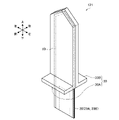
- FIG. 2 is a perspective view of the heating section 121 according to this embodiment.
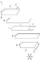
- FIG. 3 is an exploded perspective view of the heating section 121 according to this embodiment.
- FIG. 4 is a front view of the heating section 121 according to this embodiment.
- FIG. 5 is a side view of the heating section 121 according to this embodiment.
- FIG. 6 is a see-through perspective view of a portion where the heating section 121 is arranged in the suction device 100 according to this embodiment.
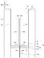
- FIG. 7 is a cross-sectional view of a portion of the suction device 100 according to the present embodiment where the heating section 121 is arranged, taken along line AA.
- the heating section 121 has an electrical resistor 10, electrical insulators 20 (20A and 20B), and rigid bodies 30 (30A and 30B). 6 and 7, the heating part 121 is arranged so as to protrude into the internal space 141 of the housing part 140. As shown in FIGS. 2 to 5, the heating section 121 has an electrical resistor 10, electrical insulators 20 (20A and 20B), and rigid bodies 30 (30A and 30B). 6 and 7, the heating part 121 is arranged so as to protrude into the internal space 141 of the housing part 140. As shown in FIGS.
- elements having substantially the same functional configuration may be distinguished by attaching different alphabets after the same reference numerals.
- multiple elements having substantially the same functional configuration are differentiated as rigid bodies 30A and 30B as appropriate.
- the rigid bodies 30A and 30B are simply referred to as the rigid bodies 30 when there is no particular need to distinguish between them.
- the direction in which the stick-shaped substrate 150 is inserted into the heating unit 121 is also referred to as the downward direction.
- the direction in which the stick-shaped base material 150 is removed from the heating unit 121 is also referred to as an upward direction.
- the upper end is also referred to as the front end, and the lower end is also referred to as the rear end.
- the vertical direction corresponds to the longitudinal direction of the electrical resistor 10, the electrical insulator 20, and the rigid body 30 (in particular, the first portion 31). Also, the vertical direction corresponds to the longitudinal direction of the heating unit 121 .
- the direction in which the electrical resistor 10, the electrical insulator 20, and the rigid body 30 overlap is also referred to as the front-rear direction.
- the front-rear direction corresponds to the thickness direction of the electrical resistor 10, the electrical insulator 20, and the rigid body 30 (in particular, the first portion 31). Also, the front-rear direction corresponds to the thickness direction of the heating portion 121 .
- a direction perpendicular to the up-down direction and the front-rear direction is also referred to as the left-right direction.
- the horizontal direction corresponds to the lateral direction of the electrical resistor 10 , the electrical insulator 20 and the rigid body 30 . Also, the horizontal direction corresponds to the lateral direction of the heating unit 121 .
- the electric resistor 10 generates heat by power supplied from the power supply section 111 .
- the electrical resistor 10 generates Joule heat when current flows.
- the electrical resistor 10 is configured as a thin conductor wire and stretched to form a plane.
- the electric resistor 10 is made of, for example, SUS (Steel Use Stainless). With such a configuration, the electrical resistor 10 can exhibit high heat resistance.
- the electrical resistor 10 is sandwiched between two electrical insulators 20 (20A and 20B). Therefore, it is possible to prevent the electrical resistor 10 from unintentionally coming into contact with another conductor and causing a short circuit. Note that the two electrical insulators 20 have the same shape.
- the electrical insulator 20 is a member having electrical insulation.
- the electrical insulator 20 is made of any material having electrical insulation.
- the electrical insulator 20 is made of polyimide. With such a configuration, the electrical insulator 20 can exhibit high heat resistance.
- the electrical insulator 20 is arranged between the electrical resistor 10 and the rigid body 30 . Therefore, it is possible to prevent a situation in which the electrical resistor 10 and the rigid body 30 come into contact with each other and cause a short circuit.
- the end of the electrical insulator 20 on the rear end side (that is, the lower side) of the heating section 121 is closer than the end of the rigid body 30 on the rear end side (that is, the lower side) of the heating section 121 . are also positioned on the rear end side (that is, on the lower side) of the heating section 121 . That is, the electrical insulator 20 extends below the rigid body 30 . With such a configuration, it is possible to more reliably prevent a situation in which the electrical resistor 10 and the rigid body 30 come into contact with each other and cause a short circuit.
- the electrical insulator 20 is configured in a film shape.
- the two film-shaped electrical insulators 20 and the electrical resistor 10 sandwiched between the two electrical insulators 20 form a so-called film heater.
- a film heater is configured by winding a conductive wire on the film surface while bending it.
- the heat distribution on the film surface can be arbitrarily designed by the distribution (that is, density) of the conductors on the film surface.
- the rigid body 30 is a member having a predetermined rigidity. According to such a configuration, the rigid body 30 exhibits rigidity against the force applied to the heating section 121, and can prevent the heating section 121 from bending.
- the rigid body 30 is also a heat conductive member.
- the rigid body 30 is heated by heat transfer from the electrical resistor 10 . Therefore, the heat generated by the electrical resistor 10 is transferred to the stick-shaped base material 150 via the rigid body 30 .
- the rigid body 30 is formed in a plate shape.
- the rigid body 30 is composed of a metal plate.
- the rigid body 30 is made of a SUS metal plate. With such a configuration, the rigid body 30 can exhibit high heat resistance.
- the rigid body 30 has a first portion 31 and a second portion 32 .
- the first portion 31 is a portion of the rigid body 30 that extends vertically (corresponding to the first direction).
- the second portion 32 is a member extending in the front-rear direction (corresponding to the second direction), which is a direction different from that of the first portion 31 .
- the rigid body 30 may be configured by bending a single metal plate.
- the second portion 32 is held by a holding portion 40 which will be described later. According to such a configuration, the second portion 32 held by the holding portion 40 can exhibit high rigidity against force applied to the first portion 31 in the front-rear direction. Therefore, the rigid body 30 can prevent the heating portion 121 from bending in the front-rear direction.
- the rigid body 30 may form an L-shape with the first portion 31 and the second portion 32 . That is, the angle formed by the first portion 31 and the second portion 32 may be 90 degrees. With such a configuration, the rigid body 30 can exhibit greater rigidity against forces applied in the front-rear direction. Therefore, it is possible to further prevent the heating portion 121 from bending in the front-rear direction.
- the stick-shaped base material 150 is inserted into the internal space 141 until the tip of the stick-shaped base material 150 contacts the second portion 32 .
- the part sandwiched by the first part 31 of the heating part 121 is inserted into the stick-shaped base material 150 . That is, the first portion 31 constitutes the outermost shell in the portion of the heating portion 121 that is inserted into the stick-shaped substrate 150 .
- the electrical resistor 10 and the electrical insulator 20 are sandwiched between two rigid bodies 30 (30A and 30B). More specifically, the electrical resistor 10 and the electrical insulator 20 are sandwiched between the first portions 31 (31A and 31B) of the two rigid bodies 30. As shown in FIG. With such a configuration, it is possible to further prevent the heating portion 121 from bending in the front-rear direction. Note that the two rigid bodies 30 have the same shape.
- the two rigid bodies 30 sandwich the electrical resistor 10 and the electrical insulator 20 with the first portion 31, and the two second portions 32 face in opposite directions to each other. placed. More simply, the electrical resistor 10 and the electrical insulator 20 are sandwiched by first portions 31 of two rigid bodies 30 arranged back-to-back. According to such a configuration, the two rigid bodies 30 form a T shape with the electrical resistor 10 and the electrical insulator 20 sandwiched therebetween. . Therefore, it is possible to further prevent the heating portion 121 from bending.
- the electric resistor 10 fits within the range sandwiched between the two electric insulators 20 .
- the left and right ends of the electrical resistor 10 are located inside the left and right ends of the electrical insulator 20 in the portion sandwiched between the two first portions 31 of the heating portion 121 .
- the upper end of the electrical resistor 10 is positioned below the upper end of the electrical insulator 20 . Therefore, the two electrical insulators 20 can sandwich the electrical resistor 10 without exposing the electrical resistor 10 to the outside in the portion of the heating unit 121 that is inserted into the stick-shaped base material 150. .
- the two electrical insulators 20 are within a range sandwiched between the two rigid bodies 30 (more specifically, the first portion 31). fits in. Specifically, the left and right ends of the electrical insulator 20 are positioned inside the left and right ends of the first portions 31 in the portion sandwiched between the two first portions 31 of the heating portion 121 . The upper end of the electrical insulator 20 is positioned below the upper end of the first portion 31 . Therefore, the first portions 31 of the two rigid bodies 30 can sandwich the electrical insulator 20 without exposing the electrical insulator 20 to the outside in the portion of the heating portion 121 that is inserted into the stick-shaped base material 150 . It becomes possible.
- the ends of the two rigid bodies 30 (more specifically, the first portions 31) that do not contact the electrical insulator 20 are joined together.
- the upper ends and the left and right ends of the first portions 31 of the two rigid bodies 30 that do not contact the electrical insulator 20 are joined without gaps.
- the electrical resistor 10 and the electrical insulator 20 sandwiched between the two rigid bodies 30 are hidden from the outside. Therefore, it is possible to prevent problems such as deterioration of heating efficiency due to foreign matter entering between the two rigid bodies 30 .
- the heating part 121 may be formed by hot-pressing the electric resistor 10, the electric insulator 20 and the rigid body 30.
- the heating portion 121 may be formed by hot-pressing the first portions 31 of the electrical resistor 10 , the two electrical insulators 20 and the two rigid bodies 30 . With such a configuration, it is possible to achieve the above-described bonding without gaps and to improve the strength of the heating portion 121 .
- the heating part 121 is inserted into the stick-shaped base material 150 from the tip of the heating part 121 . Therefore, the tip of the heating portion 121 is configured to be sharp. That is, the rigid body 30 has a sharp upper end. In this embodiment, as shown in FIG. 3, the tip of the first portion 31 is formed in the same triangular shape and joined with the vertex facing upward. Such a configuration can reduce the resistance that the heating unit 121 receives from the stick-shaped substrate 150 when the heating unit 121 is inserted into the stick-shaped substrate 150 . Therefore, it is possible to further prevent the heating portion 121 from bending.
- the electrical resistor 10 forms a heating area 11 and a non-heating area 12.
- the heating area 11 is an area of the electric resistor 10 in which the amount of heat generated per unit area is equal to or greater than a predetermined value.
- the heating area 11 is arranged on the tip side (that is, the upper side) of the heating section 121 .
- the non-heating area 12 is an area of the electric resistor 10 in which the amount of heat generated per unit area is less than a predetermined value.
- the non-heating area 12 is arranged on the rear end side (that is, below) of the heating section 121 . According to such a configuration, at least the heating area 11 can be inserted inside the stick-shaped substrate 150 . Therefore, it is possible to quickly raise the temperature of the stick-type substrate 150 .
- the boundary between the heating area 11 and the non-heating area 12 is closer to the rear end of the heating section 121 than the end of the rigid body 30 on the rear end side of the heating section 121 (i.e., below). i.e., on the lower side). That is, the heating area 11 is arranged so as to protrude below the rigid body 30 . Thereby, the heating area 11 can directly heat the first portion 31 at least at the portion in contact with the first portion 31 . Furthermore, the heating area 11 can indirectly heat the second portion 32 and the holding portion 40 in the portion protruding below the rigid body 30 . This makes it possible to efficiently heat the stick-type substrate 150 .
- the end of the electrical insulator 20 on the rear end side (that is, the lower side) of the heating section 121 is closer than the end of the rigid body 30 on the rear end side (that is, the lower side) of the heating section 121 . are also positioned on the rear end side (that is, on the lower side) of the heating section 121 . That is, the electrical insulator 20 is arranged so as to protrude below the rigid body 30 . Thereby, the electrical insulator 20 can reliably insulate the electrical resistor 10 and the rigid body 30 from each other.
- the heating part 121 may generate heat unevenly in the direction from the front end to the rear end of the heating part 121 (that is, in the vertical direction).
- the heating area 11 and the non-heating area 12 of the electrical resistor 10 may generate heat at different temperatures.
- a plurality of areas that generate heat at different temperatures may be distributed separately in the vertical direction.
- a plurality of areas that generate heat at different temperatures are arranged vertically. may be distributed separately. With such a configuration, it is possible to heat the stick-shaped substrate 150 with an optimum temperature distribution.
- the electric resistors 10 may be unevenly distributed in the direction from the front end to the rear end of the heating part 121 (that is, the vertical direction). As an example, the electric resistor 10 may be unevenly distributed between the heating area 11 and the non-heating area 12 of the electric resistor 10 . As another example, in the heating area 11, a plurality of areas having different distributions of the electrical resistors 10 may be distributed vertically. In particular, in the portion of the heating area 11 that is inserted into the stick-shaped substrate 150 (that is, the portion sandwiched between the first portions 31 of the electrical resistor 10), a plurality of areas in which the distribution of the electrical resistor 10 is different. may be separately distributed in the vertical direction. With such a configuration, it is possible to heat the heating unit 121 unevenly in the vertical direction.
- the housing portion 140 has a holding portion 40, a sealing portion 50, an interior member 60 and an exterior member .
- the exterior member 70 is a tubular member.
- the exterior member 70 may constitute the outermost shell of the suction device 100 .
- the interior member 60 is a member forming an inner wall (in particular, a side wall) of the housing portion 140 .
- the holding portion 40 and the sealing portion 50 constitute a bottom portion 143 of the housing portion 140 .
- the holding part 40 is a member that holds the heating part 121 . As shown in FIGS. 6 and 7 , the holding portion 40 holds the heating portion 121 so that the tip of the heating portion 121 protrudes from the bottom portion 143 of the housing portion 140 toward the opening 142 . According to this configuration, when the stick-shaped base material 150 is inserted into the internal space 141 through the opening 142 , the tip of the heating part 121 sticks into the stick-shaped base material 150 , and the heating part 121 is inserted into the stick-shaped base material 150 . can be inserted.
- the holding part 40 is made of a material having high heat resistance.
- the holding unit 40 is made of PEEK (Poly Ether Ether Ketone). With such a configuration, even if the heating unit 121 generates high heat, the heating unit 121 can be held continuously.
- the holding portion 40 holds the second portion 32 of the rigid body 30 .
- the holding portion 40 is configured in a plate shape. Then, the upper surface of the holding portion 40 and the lower surface of the second portion 32 of the rigid body 30 are joined, and the side surface of the holding portion 40 and the inner surface of the exterior member 70 are joined.
- the holding part 40 holds the rigid body 30 while being separated from the electrical insulator 20.
- a hole 41 is provided in the central portion of the plate-shaped holding portion 40 .
- the holding portion 40 and the heating portion 121 are positioned so that the electrical insulator 20 sandwiching the electrical resistor 10 passes through the hole 41 .
- the cross section of the hole 41 is formed wider than the cross section of the electrical insulator 20 sandwiching the electrical resistor 10 . Therefore, the holding portion 40 can hold the rigid body 30 without coming into contact with the electrical insulators 20 sandwiching the electrical resistor 10 . According to this configuration, even if the holding portion 40 and the rigid body 30 are misaligned, the electrical insulator 20 sandwiching the electrical resistor 10 is pulled by the holding portion 40 and broken. can be prevented.
- the sealing portion 50 seals the hole provided in the holding portion 40 . Specifically, the sealing portion 50 seals at least the hole 41 . If the holding portion 40 has other holes, the sealing portion 50 seals the holes. With such a configuration, it is possible to prevent the aerosol generated from the stick-shaped base material 150 from leaking into the space 144 below the bottom portion 143 of the tubular exterior member 70 . Considering that electronic devices such as the power supply unit 111 and the control unit 116 can be arranged in the space 144, it is possible to prevent failure of the suction device 100 with such a configuration.
- the holding portion 40 may be provided with the above-described air inflow holes for allowing air to flow into the internal space 141 in addition to the holes 41 .
- the air inflow hole communicates with the external space through an air flow path configured independently of the space 144 in which the electronic device is arranged.
- the sealing portion 50 seals the holes other than the air inlet holes.
- the sealing portion 50 is fixed to the holding portion 40 .
- the sealing portion 50 seals the hole provided in the holding portion 40 by being arranged in close contact with the holding portion 40 .
- the sealing portion 50 is arranged on the opposite side of the second portion 32 of the rigid body 30 with the holding portion 40 interposed therebetween.
- the sealing portion 50 is arranged so as to be in close contact with the lower surface of the holding portion 40 . According to such a configuration, it is possible to seal the space 144 below the bottom portion 143 without hindering the holding of the rigid body 30 by the holding portion 40 .
- the sealing portion 50 is arranged in contact with the electrical insulator 20 .
- the sealing portion 50 is arranged so as to be in close contact with the periphery of the electrical insulator 20 sandwiching the electrical resistor 10 . With such a configuration, it is possible to reliably seal the space 144 below the bottom portion 143 .
- the sealing portion 50 is made of a material having water repellency.
- the sealing portion 50 is made of silicon. According to such a configuration, the liquid formed by condensing the aerosol generated from the stick-shaped substrate 150 is prevented from leaking into the space 144 below the bottom portion 143 .
- one rigid body 30 forms an L shape and two rigid bodies 30 form a T shape, but the present invention is not limited to this example.
- one rigid body 30 may be bent at an obtuse angle and two rigid bodies 30 may form a Y-shape.
- one rigid body 30 may be curved to form a J shape. Even if the rigid body 30 has such a shape, the rigid body 30 exhibits high rigidity against force applied in the front-rear direction, and can prevent the heating portion 121 from bending in the front-rear direction.
- the boundary between the heating area 11 and the non-heating area 12 is closer to the rear end of the heating unit 121 (i.e., lower) than the end of the rigid body 30 on the rear end side of the heating unit 121 (i.e., below). That is, the example positioned on the lower side has been described, but the present invention is not limited to such an example.
- the boundary between the heating area 11 and the non-heating area 12 may be located at the same position as the end of the rigid body 30 on the rear end side (that is, below) of the heating section 121 . That is, the lower end of the heating area 11 may coincide with the lower end of the first portion 31 .
- the heating area 11 can directly heat the rigid body 30 in the portion of the heating portion 121 that is inserted into the stick-shaped substrate 150 .
- the heating area 11 does not protrude below the rigid body 30, i.e., the portion of the heating unit 121 that is not inserted into the stick-shaped substrate 150, heat can be more reliably transferred to other components such as the power supply unit 111. can be prevented. Therefore, it is possible to prevent failure of the suction device 100 due to heat.
- the electric resistors 10 are unevenly distributed in the vertical direction of the non-heating area 12, so that the heating unit 121 generates heat unevenly in the vertical direction.
- the heating section 121 may include a plurality of electrical resistors 10 separated in the vertical direction.
- the controller 116 may be capable of controlling power supply to each of the plurality of electrical resistors 10 . In that case, the control unit 116 may control the power supply to each of the plurality of electric resistors 10 to cause the heating unit 121 to generate heat unevenly in the vertical direction. This configuration also enables the heating unit 121 to generate heat unevenly in the vertical direction.
- the internal space 141 is a quadrangular prism as shown in FIG. 6
- the internal space 141 can take any shape such as a cylindrical shape.
- the shape of the second portion 32 of the rigid body 30 may be adjusted so as to follow the shape of the bottom surface of the housing portion 140 .
- the following configuration also belongs to the technical scope of the present invention.
- a power supply unit that supplies power
- a heating unit that heats a substrate containing an aerosol source
- the heating unit includes an electric resistor that generates heat by electric power supplied from the power supply unit, a rigid body, and an electric insulator disposed between the electric resistor and the rigid body, and is inserted into the base material.
- Ru Aerosol generation system (2) the heating unit includes two electrical insulators; The electrical resistor is sandwiched between two electrical insulators, The aerosol generating system according to (1) above.
- the heating unit includes two rigid bodies, The electrical resistor and the electrical insulator are sandwiched between the two rigid bodies, The aerosol generating system according to (2) above.
- the electric resistor falls within a range sandwiched between the two electric insulators, and the two electric insulators fall within a range sandwiched between the two rigid bodies. fits in The aerosol generating system according to (3) above.
- ends of the two rigid bodies that do not contact the electrical insulator are joined together.
- the heating part is formed by hot-pressing the electrical resistor, the electrical insulator, and the rigid body, The aerosol generating system according to any one of (1) to (5) above.
- the end of the electrical insulator on the rear end side of the heating section is located closer to the rear end of the heating section than the end of the rigid body on the rear end side of the heating section.
- the aerosol generating system according to any one of (1) to (6) above.
- the heating unit is inserted into the base material from the tip of the heating unit, The tip of the heating unit is configured to be sharp, The aerosol generating system according to any one of (1) to (7) above.
- the electric resistor includes a heating area, which is an area in which the amount of heat generated per unit area is equal to or greater than a predetermined value, located on the front end side of the heating section, and a heating area located on the rear end side of the heating section.
- the aerosol generating system according to any one of (1) to (8) above.
- the electric resistor includes a heating area, which is an area in which the amount of heat generated per unit area is equal to or greater than a predetermined value, located on the front end side of the heating section, and a heating area located on the rear end side of the heating section.
- the aerosol generating system according to any one of (1) to (8) above.
- the heating unit generates heat unevenly in the direction from the front end to the rear end of the heating unit,
- the aerosol generating system according to any one of (1) to (10) above.
- the electric resistor is unevenly distributed in the direction from the front end to the rear end of the heating part,
- the rigid body is composed of a metal plate, The aerosol generating system according to any one of (1) to (12) above.
- the rigid body is composed of a SUS metal plate, The aerosol generating system according to (13) above.
- the electrical insulator is composed of polyimide, The aerosol generating system according to (1) to 14 above.
- the electrical insulator is configured in the form of a film, The aerosol generating system according to any one of (1) to (15) above.
- the electrical resistor is made of SUS, The aerosol generating system according to any one of (1) to (16) above.
- the aerosol generating system comprises: an accommodating portion having an internal space and an opening that communicates the internal space with the outside, and containing the substrate inserted into the internal space through the opening; a holding portion that holds the rigid body so that the tip side of the heating portion protrudes from the bottom portion of the housing portion toward the opening; comprising a The aerosol generating system according to any one of (1) to (17) above. (19) The holding part holds the rigid body in a state separated from the electrical insulator, The aerosol generating system according to (18) above. (20) wherein the aerosol-generating system comprises the substrate; The aerosol generating system according to any one of (1) to (19) above.
- suction device 111 power supply unit 112 sensor unit 113 notification unit 114 storage unit 115 communication unit 116 control unit 121 heating unit 140 storage unit 141 internal space 142 opening 143 bottom 150 stick-shaped substrate 151 substrate 152 mouthpiece 10 electric resistor REFERENCE SIGNS LIST 11 heating area 12 non-heating area 20 electrical insulator 30 rigid body 31 first part 32 second part 40 holding part 41 hole 50 sealing part 60 interior member 70 exterior member
Landscapes
- Chemical & Material Sciences (AREA)
- Health & Medical Sciences (AREA)
- Chemical Kinetics & Catalysis (AREA)
- Medicinal Chemistry (AREA)
- Polymers & Plastics (AREA)
- Organic Chemistry (AREA)
- Resistance Heating (AREA)
- Electrostatic Spraying Apparatus (AREA)
- Fuel Cell (AREA)
Abstract
Description
本構成例に係る吸引装置は、エアロゾル源を含む基材を基材内部から加熱することでエアロゾルを生成する。以下、図1を参照しながら、本構成例を説明する。
図2は、本実施形態に係る加熱部121の斜視図である。図3は、本実施形態に係る加熱部121の分解斜視図である。図4は、本実施形態に係る加熱部121の正面図である。図5は、本実施形態に係る加熱部121の側面図である。図6は、本実施形態に係る吸引装置100における加熱部121が配置された部分の透過斜視図である。図7は、本実施形態に係る吸引装置100における加熱部121が配置された部分のA-A切断線における断面図である。
以上、添付図面を参照しながら本発明の好適な実施形態について詳細に説明したが、本発明はかかる例に限定されない。本発明の属する技術の分野における通常の知識を有する者であれば、請求の範囲に記載された技術的思想の範疇内において、各種の変更例または修正例に想到し得ることは明らかであり、これらについても、当然に本発明の技術的範囲に属するものと了解される。
(1)
電力を供給する電力供給部と、
エアロゾル源を含有した基材を加熱する加熱部と、
を備え、
前記加熱部は、前記電力供給部から供給された電力により発熱する電気抵抗体、剛体、及び前記電気抵抗体と前記剛体との間に配置される電気絶縁体を含み、前記基材に挿入される、
エアロゾル生成システム。
(2)
前記加熱部は、2つの前記電気絶縁体を含み、
前記電気抵抗体は、2つの前記電気絶縁体により挟まれる、
前記(1)に記載のエアロゾル生成システム。
(3)
前記加熱部は、2つの前記剛体を含み、
前記電気抵抗体及び前記電気絶縁体は、2つの前記剛体により挟まれる、
前記(2)に記載のエアロゾル生成システム。
(4)
前記加熱部のうち前記基材に挿入される部分において、前記電気抵抗体は2つの前記電気絶縁体により挟まれる範囲内に収まり、2つの前記電気絶縁体は2つの前記剛体により挟まれる範囲内に収まる、
前記(3)に記載のエアロゾル生成システム。
(5)
前記加熱部のうち前記基材に挿入される部分において、2つの前記剛体のうち前記電気絶縁体に接触しない端部同士が接合される、
前記(4)に記載のエアロゾル生成システム。
(6)
前記加熱部は、前記電気抵抗体、前記電気絶縁体、及び前記剛体がホットプレスされることで、形成される、
前記(1)~(5)のいずれか一項に記載のエアロゾル生成システム。
(7)
前記加熱部の後端側における前記電気絶縁体の端部は、前記加熱部の後端側における前記剛体の端部よりも前記加熱部の後端側に位置する、
前記(1)~(6)のいずれか一項に記載のエアロゾル生成システム。
(8)
前記加熱部は、前記加熱部の先端から前記基材に挿入され、
前記加熱部の先端は、鋭利に構成される、
前記(1)~(7)のいずれか一項に記載のエアロゾル生成システム。
(9)
前記電気抵抗体は、前記加熱部の先端側に配置される単位面積当たりの発熱量が所定値以上であるエリアである加熱エリア、及び前記加熱部の後端側に配置される単位面積当たりの発熱量が所定値未満であるエリアである非加熱エリアと、を形成し、
前記加熱エリアと前記非加熱エリアとの境界は、前記加熱部の後端側における前記剛体の端部よりも前記加熱部の後端側に位置する、
前記(1)~(8)のいずれか一項に記載のエアロゾル生成システム。
(10)
前記電気抵抗体は、前記加熱部の先端側に配置される単位面積当たりの発熱量が所定値以上であるエリアである加熱エリア、及び前記加熱部の後端側に配置される単位面積当たりの発熱量が所定値未満であるエリアである非加熱エリアと、を形成し、
前記加熱エリアと前記非加熱エリアとの境界は、前記加熱部の後端側における前記剛体の端部と同じ位置に位置する、
前記(1)~(8)のいずれか一項に記載のエアロゾル生成システム。
(11)
前記加熱部は、前記加熱部の先端から後端への方向において不均一に発熱する、
前記(1)~(10)のいずれか一項に記載のエアロゾル生成システム。
(12)
前記電気抵抗体は、前記加熱部の先端から後端への方向において不均一に分布する、
前記(11)に記載のエアロゾル生成システム。
(13)
前記剛体は、金属板により構成される、
前記(1)~(12)のいずれか一項に記載のエアロゾル生成システム。
(14)
前記剛体は、SUS金属板により構成される、
前記(13)に記載のエアロゾル生成システム。
(15)
前記電気絶縁体は、ポリイミドにより構成される、
前記(1)~14に記載のエアロゾル生成システム。
(16)
前記電気絶縁体は、フィルム状に構成される、
前記(1)~(15)のいずれか一項に記載のエアロゾル生成システム。
(17)
前記電気抵抗体は、SUSにより構成される、
前記(1)~(16)のいずれか一項に記載のエアロゾル生成システム。
(18)
前記エアロゾル生成システムは、
内部空間及び前記内部空間を外部に連通する開口を有し、前記開口から前記内部空間に挿入された前記基材を収容する収容部と、
前記加熱部の先端側が前記収容部の底部から前記開口に向かう方向に突出するように、前記剛体を保持する保持部と、
を備える、
前記(1)~(17)のいずれか一項に記載のエアロゾル生成システム。
(19)
前記保持部は、前記電気絶縁体から離隔した状態で、前記剛体を保持する、
前記(18)に記載のエアロゾル生成システム。
(20)
前記エアロゾル生成システムは、前記基材を含む、
前記(1)~(19)のいずれか一項に記載のエアロゾル生成システム。
111 電源部
112 センサ部
113 通知部
114 記憶部
115 通信部
116 制御部
121 加熱部
140 収容部
141 内部空間
142 開口
143 底部
150 スティック型基材
151 基材部
152 吸口部
10 電気抵抗体
11 加熱エリア
12 非加熱エリア
20 電気絶縁体
30 剛体
31 第1部分
32 第2部分
40 保持部
41 孔
50 封止部
60 内装部材
70 外装部材
Claims (20)
- 電力を供給する電力供給部と、
エアロゾル源を含有した基材を加熱する加熱部と、
を備え、
前記加熱部は、前記電力供給部から供給された電力により発熱する電気抵抗体、剛体、及び前記電気抵抗体と前記剛体との間に配置される電気絶縁体を含み、前記基材に挿入される、
エアロゾル生成システム。 - 前記加熱部は、2つの前記電気絶縁体を含み、
前記電気抵抗体は、2つの前記電気絶縁体により挟まれる、
請求項1に記載のエアロゾル生成システム。 - 前記加熱部は、2つの前記剛体を含み、
前記電気抵抗体及び前記電気絶縁体は、2つの前記剛体により挟まれる、
請求項2に記載のエアロゾル生成システム。 - 前記加熱部のうち前記基材に挿入される部分において、前記電気抵抗体は2つの前記電気絶縁体により挟まれる範囲内に収まり、2つの前記電気絶縁体は2つの前記剛体により挟まれる範囲内に収まる、
請求項3に記載のエアロゾル生成システム。 - 前記加熱部のうち前記基材に挿入される部分において、2つの前記剛体のうち前記電気絶縁体に接触しない端部同士が接合される、
請求項4に記載のエアロゾル生成システム。 - 前記加熱部は、前記電気抵抗体、前記電気絶縁体、及び前記剛体がホットプレスされることで、形成される、
請求項1~5のいずれか一項に記載のエアロゾル生成システム。 - 前記加熱部の後端側における前記電気絶縁体の端部は、前記加熱部の後端側における前記剛体の端部よりも前記加熱部の後端側に位置する、
請求項1~6のいずれか一項に記載のエアロゾル生成システム。 - 前記加熱部は、前記加熱部の先端から前記基材に挿入され、
前記加熱部の先端は、鋭利に構成される、
請求項1~7のいずれか一項に記載のエアロゾル生成システム。 - 前記電気抵抗体は、前記加熱部の先端側に配置される単位面積当たりの発熱量が所定値以上であるエリアである加熱エリア、及び前記加熱部の後端側に配置される単位面積当たりの発熱量が所定値未満であるエリアである非加熱エリアと、を形成し、
前記加熱エリアと前記非加熱エリアとの境界は、前記加熱部の後端側における前記剛体の端部よりも前記加熱部の後端側に位置する、
請求項1~8のいずれか一項に記載のエアロゾル生成システム。 - 前記電気抵抗体は、前記加熱部の先端側に配置される単位面積当たりの発熱量が所定値以上であるエリアである加熱エリア、及び前記加熱部の後端側に配置される単位面積当たりの発熱量が所定値未満であるエリアである非加熱エリアと、を形成し、
前記加熱エリアと前記非加熱エリアとの境界は、前記加熱部の後端側における前記剛体の端部と同じ位置に位置する、
請求項1~8のいずれか一項に記載のエアロゾル生成システム。 - 前記加熱部は、前記加熱部の先端から後端への方向において不均一に発熱する、
請求項1~10のいずれか一項に記載のエアロゾル生成システム。 - 前記電気抵抗体は、前記加熱部の先端から後端への方向において不均一に分布する、
請求項11に記載のエアロゾル生成システム。 - 前記剛体は、金属板により構成される、
請求項1~12のいずれか一項に記載のエアロゾル生成システム。 - 前記剛体は、SUS金属板により構成される、
請求項13に記載のエアロゾル生成システム。 - 前記電気絶縁体は、ポリイミドにより構成される、
請求項1~14に記載のエアロゾル生成システム。 - 前記電気絶縁体は、フィルム状に構成される、
請求項1~15のいずれか一項に記載のエアロゾル生成システム。 - 前記電気抵抗体は、SUSにより構成される、
請求項1~16のいずれか一項に記載のエアロゾル生成システム。 - 前記エアロゾル生成システムは、
内部空間及び前記内部空間を外部に連通する開口を有し、前記開口から前記内部空間に挿入された前記基材を収容する収容部と、
前記加熱部の先端側が前記収容部の底部から前記開口に向かう方向に突出するように、前記剛体を保持する保持部と、
を備える、
請求項1~17のいずれか一項に記載のエアロゾル生成システム。 - 前記保持部は、前記電気絶縁体から離隔した状態で、前記剛体を保持する、
請求項18に記載のエアロゾル生成システム。 - 前記エアロゾル生成システムは、前記基材を含む、
請求項1~19のいずれか一項に記載のエアロゾル生成システム。
Priority Applications (7)
| Application Number | Priority Date | Filing Date | Title |
|---|---|---|---|
| CN202180098704.5A CN117412683A (zh) | 2021-06-28 | 2021-06-28 | 气溶胶生成系统 |
| PCT/JP2021/024407 WO2023275949A1 (ja) | 2021-06-28 | 2021-06-28 | エアロゾル生成システム |
| KR1020237041498A KR20240006053A (ko) | 2021-06-28 | 2021-06-28 | 에어로졸 생성 시스템 |
| JP2023531164A JP7518294B2 (ja) | 2021-06-28 | 2021-06-28 | エアロゾル生成システム |
| EP21948261.9A EP4338620A4 (en) | 2021-06-28 | 2021-06-28 | AEROSOL GENERATING SYSTEM |
| TW110140768A TWI859477B (zh) | 2021-06-28 | 2021-11-02 | 霧氣生成系統 |
| US18/490,559 US20240065328A1 (en) | 2021-06-28 | 2023-10-19 | Aerosol generation system |
Applications Claiming Priority (1)
| Application Number | Priority Date | Filing Date | Title |
|---|---|---|---|
| PCT/JP2021/024407 WO2023275949A1 (ja) | 2021-06-28 | 2021-06-28 | エアロゾル生成システム |
Related Child Applications (1)
| Application Number | Title | Priority Date | Filing Date |
|---|---|---|---|
| US18/490,559 Continuation US20240065328A1 (en) | 2021-06-28 | 2023-10-19 | Aerosol generation system |
Publications (1)
| Publication Number | Publication Date |
|---|---|
| WO2023275949A1 true WO2023275949A1 (ja) | 2023-01-05 |
Family
ID=84690995
Family Applications (1)
| Application Number | Title | Priority Date | Filing Date |
|---|---|---|---|
| PCT/JP2021/024407 Ceased WO2023275949A1 (ja) | 2021-06-28 | 2021-06-28 | エアロゾル生成システム |
Country Status (7)
| Country | Link |
|---|---|
| US (1) | US20240065328A1 (ja) |
| EP (1) | EP4338620A4 (ja) |
| JP (1) | JP7518294B2 (ja) |
| KR (1) | KR20240006053A (ja) |
| CN (1) | CN117412683A (ja) |
| TW (1) | TWI859477B (ja) |
| WO (1) | WO2023275949A1 (ja) |
Citations (8)
| Publication number | Priority date | Publication date | Assignee | Title |
|---|---|---|---|---|
| JPH01154485A (ja) * | 1987-12-10 | 1989-06-16 | Hitachi Metals Ltd | 面状ヒータ |
| JPH04188586A (ja) * | 1990-11-20 | 1992-07-07 | Matsushita Electric Ind Co Ltd | 面ヒータ |
| JP2003031341A (ja) * | 2001-07-13 | 2003-01-31 | Espec Corp | プレートヒータ |
| JP2007157488A (ja) * | 2005-12-05 | 2007-06-21 | Sankei Giken:Kk | 面状発熱体 |
| JP2014212045A (ja) * | 2013-04-19 | 2014-11-13 | 株式会社クリエイティブ テクノロジー | 面状発熱体 |
| JP5854394B2 (ja) | 2012-12-28 | 2016-02-09 | フィリップ・モーリス・プロダクツ・ソシエテ・アノニム | エアロゾル発生システムのための加熱アセンブリ |
| JP2018511316A (ja) * | 2015-03-31 | 2018-04-26 | フィリップ・モーリス・プロダクツ・ソシエテ・アノニム | エアロゾル発生システム用の長いヒーター組立品および加熱組立品 |
| JP2020501610A (ja) * | 2016-12-16 | 2020-01-23 | ケーティー・アンド・ジー・コーポレーション | エアロゾル生成方法及びその装置 |
Family Cites Families (5)
| Publication number | Priority date | Publication date | Assignee | Title |
|---|---|---|---|---|
| KR102583037B1 (ko) * | 2017-05-16 | 2023-09-27 | 이충언 | 에어로졸을 발생시키는 가열소자 및 이를 이용한 흡연장치 |
| JP7128215B2 (ja) * | 2017-06-09 | 2022-08-30 | フィリップ・モーリス・プロダクツ・ソシエテ・アノニム | 適合可能なエアロゾル発生システム |
| CN209376679U (zh) * | 2018-09-28 | 2019-09-13 | 深圳市合元科技有限公司 | 烘焙烟具 |
| CN212488476U (zh) * | 2020-05-12 | 2021-02-09 | 威滔电子科技(深圳)有限公司 | 一种发热组件及气溶胶产生装置 |
| CN112244359B (zh) * | 2020-09-30 | 2024-08-09 | 深圳麦时科技有限公司 | 发热体、发热组件和加热装置 |
-
2021
- 2021-06-28 CN CN202180098704.5A patent/CN117412683A/zh active Pending
- 2021-06-28 KR KR1020237041498A patent/KR20240006053A/ko active Pending
- 2021-06-28 WO PCT/JP2021/024407 patent/WO2023275949A1/ja not_active Ceased
- 2021-06-28 JP JP2023531164A patent/JP7518294B2/ja active Active
- 2021-06-28 EP EP21948261.9A patent/EP4338620A4/en active Pending
- 2021-11-02 TW TW110140768A patent/TWI859477B/zh active
-
2023
- 2023-10-19 US US18/490,559 patent/US20240065328A1/en active Pending
Patent Citations (8)
| Publication number | Priority date | Publication date | Assignee | Title |
|---|---|---|---|---|
| JPH01154485A (ja) * | 1987-12-10 | 1989-06-16 | Hitachi Metals Ltd | 面状ヒータ |
| JPH04188586A (ja) * | 1990-11-20 | 1992-07-07 | Matsushita Electric Ind Co Ltd | 面ヒータ |
| JP2003031341A (ja) * | 2001-07-13 | 2003-01-31 | Espec Corp | プレートヒータ |
| JP2007157488A (ja) * | 2005-12-05 | 2007-06-21 | Sankei Giken:Kk | 面状発熱体 |
| JP5854394B2 (ja) | 2012-12-28 | 2016-02-09 | フィリップ・モーリス・プロダクツ・ソシエテ・アノニム | エアロゾル発生システムのための加熱アセンブリ |
| JP2014212045A (ja) * | 2013-04-19 | 2014-11-13 | 株式会社クリエイティブ テクノロジー | 面状発熱体 |
| JP2018511316A (ja) * | 2015-03-31 | 2018-04-26 | フィリップ・モーリス・プロダクツ・ソシエテ・アノニム | エアロゾル発生システム用の長いヒーター組立品および加熱組立品 |
| JP2020501610A (ja) * | 2016-12-16 | 2020-01-23 | ケーティー・アンド・ジー・コーポレーション | エアロゾル生成方法及びその装置 |
Non-Patent Citations (1)
| Title |
|---|
| See also references of EP4338620A4 |
Also Published As
| Publication number | Publication date |
|---|---|
| TW202300035A (zh) | 2023-01-01 |
| TWI859477B (zh) | 2024-10-21 |
| JP7518294B2 (ja) | 2024-07-17 |
| EP4338620A1 (en) | 2024-03-20 |
| KR20240006053A (ko) | 2024-01-12 |
| EP4338620A4 (en) | 2025-04-30 |
| JPWO2023275949A1 (ja) | 2023-01-05 |
| CN117412683A (zh) | 2024-01-16 |
| US20240065328A1 (en) | 2024-02-29 |
Similar Documents
| Publication | Publication Date | Title |
|---|---|---|
| CN113677227A (zh) | 电子气雾剂供应系统 | |
| WO2021260894A1 (ja) | 吸引装置、制御方法、及びプログラム | |
| US20240081408A1 (en) | Aerosol generation system | |
| US20230000152A1 (en) | Inhaling device, control method, and non-transitory computer readable medium | |
| WO2022064560A1 (ja) | 吸引装置、制御装置、及び制御方法 | |
| JP7518295B2 (ja) | エアロゾル生成システム | |
| JP7498865B2 (ja) | エアロゾル生成システム | |
| WO2023275949A1 (ja) | エアロゾル生成システム | |
| JP7544977B2 (ja) | エアロゾル生成システム | |
| JP7595169B2 (ja) | エアロゾル生成システム | |
| JP7544978B2 (ja) | エアロゾル生成システム | |
| JP7595168B2 (ja) | エアロゾル生成システム | |
| CN118401135A (zh) | 气溶胶生成装置 | |
| JP7646002B2 (ja) | エアロゾル生成システム | |
| WO2023286143A1 (ja) | エアロゾル生成システム | |
| CN120751949A (zh) | 用于气溶胶产生装置的电源单元和气溶胶产生装置 | |
| WO2022190281A1 (ja) | 吸引装置 | |
| WO2023275956A1 (ja) | エアロゾル生成システム |
Legal Events
| Date | Code | Title | Description |
|---|---|---|---|
| 121 | Ep: the epo has been informed by wipo that ep was designated in this application |
Ref document number: 21948261 Country of ref document: EP Kind code of ref document: A1 |
|
| WWE | Wipo information: entry into national phase |
Ref document number: 2023531164 Country of ref document: JP |
|
| WWE | Wipo information: entry into national phase |
Ref document number: 202180098704.5 Country of ref document: CN |
|
| ENP | Entry into the national phase |
Ref document number: 20237041498 Country of ref document: KR Kind code of ref document: A |
|
| WWE | Wipo information: entry into national phase |
Ref document number: 2021948261 Country of ref document: EP |
|
| NENP | Non-entry into the national phase |
Ref country code: DE |
|
| ENP | Entry into the national phase |
Ref document number: 2021948261 Country of ref document: EP Effective date: 20240129 |