WO2023286302A1 - Dispositif de commande - Google Patents
Dispositif de commande Download PDFInfo
- Publication number
- WO2023286302A1 WO2023286302A1 PCT/JP2022/004442 JP2022004442W WO2023286302A1 WO 2023286302 A1 WO2023286302 A1 WO 2023286302A1 JP 2022004442 W JP2022004442 W JP 2022004442W WO 2023286302 A1 WO2023286302 A1 WO 2023286302A1
- Authority
- WO
- WIPO (PCT)
- Prior art keywords
- state
- engine
- timing
- control device
- vehicle
- Prior art date
- Legal status (The legal status is an assumption and is not a legal conclusion. Google has not performed a legal analysis and makes no representation as to the accuracy of the status listed.)
- Ceased
Links
Images


Classifications
-
- F—MECHANICAL ENGINEERING; LIGHTING; HEATING; WEAPONS; BLASTING
- F02—COMBUSTION ENGINES; HOT-GAS OR COMBUSTION-PRODUCT ENGINE PLANTS
- F02D—CONTROLLING COMBUSTION ENGINES
- F02D11/00—Arrangements for, or adaptations to, non-automatic engine control initiation means, e.g. operator initiated
- F02D11/06—Arrangements for, or adaptations to, non-automatic engine control initiation means, e.g. operator initiated characterised by non-mechanical control linkages, e.g. fluid control linkages or by control linkages with power drive or assistance
- F02D11/10—Arrangements for, or adaptations to, non-automatic engine control initiation means, e.g. operator initiated characterised by non-mechanical control linkages, e.g. fluid control linkages or by control linkages with power drive or assistance of the electric type
-
- F—MECHANICAL ENGINEERING; LIGHTING; HEATING; WEAPONS; BLASTING
- F02—COMBUSTION ENGINES; HOT-GAS OR COMBUSTION-PRODUCT ENGINE PLANTS
- F02D—CONTROLLING COMBUSTION ENGINES
- F02D29/00—Controlling engines, such controlling being peculiar to the devices driven thereby, the devices being other than parts or accessories essential to engine operation, e.g. controlling of engines by signals external thereto
- F02D29/02—Controlling engines, such controlling being peculiar to the devices driven thereby, the devices being other than parts or accessories essential to engine operation, e.g. controlling of engines by signals external thereto peculiar to engines driving vehicles; peculiar to engines driving variable pitch propellers
-
- F—MECHANICAL ENGINEERING; LIGHTING; HEATING; WEAPONS; BLASTING
- F02—COMBUSTION ENGINES; HOT-GAS OR COMBUSTION-PRODUCT ENGINE PLANTS
- F02D—CONTROLLING COMBUSTION ENGINES
- F02D41/00—Electrical control of supply of combustible mixture or its constituents
- F02D41/02—Circuit arrangements for generating control signals
- F02D41/04—Introducing corrections for particular operating conditions
- F02D41/045—Detection of accelerating or decelerating state
-
- F—MECHANICAL ENGINEERING; LIGHTING; HEATING; WEAPONS; BLASTING
- F02—COMBUSTION ENGINES; HOT-GAS OR COMBUSTION-PRODUCT ENGINE PLANTS
- F02D—CONTROLLING COMBUSTION ENGINES
- F02D41/00—Electrical control of supply of combustible mixture or its constituents
- F02D41/02—Circuit arrangements for generating control signals
- F02D41/14—Introducing closed-loop corrections
- F02D41/1438—Introducing closed-loop corrections using means for determining characteristics of the combustion gases; Sensors therefor
- F02D41/1473—Introducing closed-loop corrections using means for determining characteristics of the combustion gases; Sensors therefor characterised by the regulation method
- F02D41/1475—Regulating the air fuel ratio at a value other than stoichiometry
-
- F—MECHANICAL ENGINEERING; LIGHTING; HEATING; WEAPONS; BLASTING
- F02—COMBUSTION ENGINES; HOT-GAS OR COMBUSTION-PRODUCT ENGINE PLANTS
- F02D—CONTROLLING COMBUSTION ENGINES
- F02D41/00—Electrical control of supply of combustible mixture or its constituents
- F02D41/02—Circuit arrangements for generating control signals
- F02D41/18—Circuit arrangements for generating control signals by measuring intake air flow
-
- F—MECHANICAL ENGINEERING; LIGHTING; HEATING; WEAPONS; BLASTING
- F02—COMBUSTION ENGINES; HOT-GAS OR COMBUSTION-PRODUCT ENGINE PLANTS
- F02D—CONTROLLING COMBUSTION ENGINES
- F02D41/00—Electrical control of supply of combustible mixture or its constituents
- F02D41/30—Controlling fuel injection
- F02D41/3011—Controlling fuel injection according to or using specific or several modes of combustion
- F02D41/3017—Controlling fuel injection according to or using specific or several modes of combustion characterised by the mode(s) being used
- F02D41/3023—Controlling fuel injection according to or using specific or several modes of combustion characterised by the mode(s) being used a mode being the stratified charge spark-ignited mode
-
- F—MECHANICAL ENGINEERING; LIGHTING; HEATING; WEAPONS; BLASTING
- F02—COMBUSTION ENGINES; HOT-GAS OR COMBUSTION-PRODUCT ENGINE PLANTS
- F02D—CONTROLLING COMBUSTION ENGINES
- F02D41/00—Electrical control of supply of combustible mixture or its constituents
- F02D41/0002—Controlling intake air
- F02D2041/001—Controlling intake air for engines with variable valve actuation
-
- F—MECHANICAL ENGINEERING; LIGHTING; HEATING; WEAPONS; BLASTING
- F02—COMBUSTION ENGINES; HOT-GAS OR COMBUSTION-PRODUCT ENGINE PLANTS
- F02D—CONTROLLING COMBUSTION ENGINES
- F02D41/00—Electrical control of supply of combustible mixture or its constituents
- F02D41/02—Circuit arrangements for generating control signals
- F02D41/14—Introducing closed-loop corrections
- F02D41/1401—Introducing closed-loop corrections characterised by the control or regulation method
- F02D2041/1412—Introducing closed-loop corrections characterised by the control or regulation method using a predictive controller
-
- F—MECHANICAL ENGINEERING; LIGHTING; HEATING; WEAPONS; BLASTING
- F02—COMBUSTION ENGINES; HOT-GAS OR COMBUSTION-PRODUCT ENGINE PLANTS
- F02D—CONTROLLING COMBUSTION ENGINES
- F02D41/00—Electrical control of supply of combustible mixture or its constituents
- F02D41/30—Controlling fuel injection
- F02D41/3011—Controlling fuel injection according to or using specific or several modes of combustion
- F02D41/3076—Controlling fuel injection according to or using specific or several modes of combustion with special conditions for selecting a mode of combustion, e.g. for starting, for diagnosing
Definitions
- the present invention relates to a control device.
- the mixture ratio indicated by the amount of air and fuel injection is controlled to the optimum value so that the efficiency of the catalyst is maximized.
- Patent Document 1 describes a technique for quickly switching to lean combustion by VTC control in response to the problem of response delay in the amount of air, which is a problem when switching between normal combustion and lean combustion.
- An object of the present invention is to provide a control device that can reduce the energy consumption of actuators.
- the present invention provides a control device for an actuator used for acceleration of a vehicle, wherein the actuator is controlled to at least two operating states, has a response delay in control, and At a first timing, the device predicts whether or not there is a request to accelerate the vehicle for each predetermined time period from the first timing to the second timing, and stores whether or not there is a request for acceleration of the vehicle for each predetermined time period.
- the operating state of the actuator at the first timing is the first state and it is predicted that there is no acceleration request from the third timing to the second timing within the period, the actuator operates within the period; The state is changed from the first state to the energy saving second state.
- the energy consumption of the actuator can be reduced.
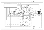
- FIG. 1 is a system configuration diagram showing the configuration of an internal combustion engine system to which the present invention is applied;
- FIG. FIG. 4 is a diagram showing the engine operating range and the behavior of the engine operating point when the driver accelerates or decelerates.
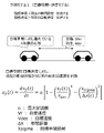
- FIG. 4 is an explanatory diagram of a prediction principle (prediction model 1) of a re-acceleration prediction function;
- FIG. 4 is an explanatory diagram of a prediction principle (prediction model 2) of a re-acceleration prediction function;
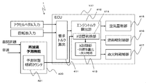
- 1 is a block diagram illustrating the configuration of an embodiment of the present invention;
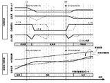
- FIG. 4 is a time chart of engine control based on the re-acceleration prediction function of the embodiment of the present invention; 4 is a flowchart for explaining processing in each block according to the embodiment of the present invention;
- This embodiment relates to a vehicle control device that controls an engine so as to improve fuel efficiency while taking into account the driving characteristics of the driver and the efficiency of the engine or hybrid system.
- the present invention relates to a control device for an internal combustion engine that predicts and expands the fuel-saving operating range of the engine.
- An object of the present embodiment is, for example, in a vehicle equipped with an engine, to solve the problem of response delay when switching the combustion state of the engine when the engine is operated under low load or high load.
- By predicting the deceleration it is determined that the engine will be in a low load state or a high load state in the future, and preparations are made in advance to switch the combustion state, resulting in low load and high load states.
- FIG. 1 shows the system configuration of an internal combustion engine to which the present invention is applied, and the internal combustion engine shows a cross section of one cylinder.
- An airflow meter 101 for measuring the amount of intake air is installed in the intake passage of the internal combustion engine 100, and a throttle valve 102 for adjusting the amount of intake air is installed downstream thereof.
- the air amount output of the airflow meter 101 and the opening degree output of the throttle valve 102 are sent to an ECU (engine control unit) 107 .
- the internal combustion engine 100 has a fuel injection valve 103 that directly injects fuel into the cylinder 112 .
- the fuel injection valve 103 is connected to a fuel supply passage 114 and supplied with high-pressure fuel.
- a spark plug connected to the spark ignition device 109 is provided at the top of the cylinder 112 .
- a piston 113 is mounted in the cylinder 112 so as to be vertically movable.
- the crankshaft which converts the vertical motion of the piston 113 into rotational motion, is provided with a crank angle signal plate 105 and a crank angle sensor 106 for detecting the rotational angular velocity (rotational speed of the internal combustion engine) and angular position.
- a signal from the crank angle sensor 106 is transmitted to the ECU 107 .
- Internal combustion engine 100 also includes a camshaft 116 for opening and closing intake valves 117 .
- the camshaft 116 is connected to the crankshaft by a timing belt or metal chain and rotates in conjunction with the rotation of the crankshaft.
- the camshaft 116 also has a cam angle signal plate 118 and a cam angle sensor 115 for detecting its rotational angular velocity and angular position.
- the intake valve 117 is provided with an intake VTC (Valve Timing Control) capable of changing the angular phase difference of the intake side camshaft so that the opening/closing timing of the intake valve 117 can be changed.
- the intake VTC is controlled by a signal from the ECU 107 .
- Fuel pressure sensor 104 is a sensor for measuring the pressure in fuel supply passage 114 to fuel injection valve 103 .
- a water temperature sensor 108 is attached to a cooling water passage of the internal combustion engine 100 and is a sensor for measuring the cooling water temperature of the internal combustion engine.
- the valve opening detection sensor 110 is a sensor for detecting the opening timing of the fuel injection valve 103 . Valve opening detection sensor 110 can also be used as a knock sensor for detecting knocking.
- the throttle valve 102 adjusts the amount of intake air.
- the air flow meter 101 measures the amount of intake air whose intake amount has been adjusted by the throttle valve 102, and the signal is transmitted to the ECU 07. After that, the intake air passes through the intake valve 117 and enters the cylinder 112 of the internal combustion engine to form an air-fuel mixture with the fuel injected from the fuel injection valve 103 .
- the fuel injection valve 103 is energized by a signal from the ECU 107 to be controlled to open and close to inject fuel.
- a mixture of fuel and intake air formed in the cylinder 112 is ignited by the spark ignition device 109 .
- the spark ignition device 109 is ignition controlled by a signal from the ECU 107 .
- the ignited air-fuel mixture burns and expands to push the piston 113 downward.
- the output shaft (crankshaft) is connected to the piston 113, rotates when the piston 113 is pushed down, and outputs engine torque.
- the air-fuel mixture that has finished burning becomes exhaust gas and is sent to the three-way catalyst 120 through the exhaust pipe 119 .
- the three-way catalyst 120 has the function of converting harmful nitrogen oxides and carbon monoxide contained in the exhaust gas into harmless substances such as carbon dioxide, water and nitrogen through oxidation/reduction reactions.
- the A/F sensor 121 detects the amount of oxygen contained in the exhaust gas and transmits the sensor output to the ECU 107 .
- the ECU 107 determines from the output of the A/F sensor 121 whether the air-fuel ratio is excessive fuel (rich) or oxygen excessive (lean), and controls the air-fuel ratio.
- FIG. 2 is a diagram showing driving conditions to which the control described in this embodiment is applied.
- the horizontal axis indicates the engine speed
- the vertical axis indicates the engine torque.
- the engine speed increases toward the right side
- the engine torque output increases toward the upper side.
- the amount of air and the amount of fuel injection are controlled so as to be approximately 1 in the entire range regardless of the magnitude of the engine torque or the magnitude of the engine torque.
- Lean burn has a larger amount of air than normal combustion, and it is necessary to open the throttle valve 102 more. Therefore, the pumping loss during intake is reduced. Also, during lean-burn combustion, the combustion speed is slow and the combustion temperature is lower than in normal combustion. Therefore, cooling loss can be reduced, and extra work corresponding to the cooling loss can be reduced.
- the curve indicated by the dots in Figure 2 shows the behavior of the vehicle during acceleration and deceleration. At the Start point in FIG. 2, both the engine speed and the engine torque are high, and the load on the engine is high.
- Figures 3A and 3B are examples of a model that determines whether or not the vehicle will accelerate based on the behavior of the preceding vehicle.
- the prediction model 1 shown in FIG. 3A is a model that measures the inter-vehicle distance and vehicle speed and expresses the driver's psychology with respect to the target inter-vehicle distance and target speed by acceleration.
- the formula for this model is given by
- Vf(t) indicates the current vehicle speed and Vdes indicates the target vehicle speed.
- Vdes indicates the target vehicle speed.
- Xsigma is the target inter-vehicle distance and ⁇ X(t) is the current inter-vehicle distance.
- the inter-vehicle distance term used exceeds 1.
- a re-acceleration prediction function 420 (Fig. 4), which will be described later, uses such a model to quantitatively evaluate the driver's intention to accelerate. Expect lower engine loads.
- the re-acceleration prediction function 420 calculates the positional relationship with the preceding vehicle after an arbitrary time elapses. If it is determined that the inter-vehicle distance will be shorter than the predetermined inter-vehicle distance after the elapse of the predetermined time, the vehicle will decelerate. You can also
- the re-acceleration prediction function 420 reads the driver's psychology of accelerating or decelerating, and predicts that the engine will have a high load when accelerating and a low engine load when decelerating. .
- FIG. 4 is a block diagram showing the essential parts of the control device 1 according to the embodiment.
- the control device 1 of this embodiment includes a re-acceleration prediction function 420 and an ECU (engine control unit) 107 .
- ECU engine control unit
- the re-acceleration prediction function 420 is realized, for example, by an electronic control device separate from the ECU 107, an integrated circuit (for example, FPGA: Field Programmable Gate Array), or the like, but may be realized by the ECU 107.
- the ECU 107 and the electronic control unit are configured by, for example, a processor such as a CPU (Central Processing Unit), a storage device such as a memory, a communication I/F (input/output circuit), etc., and the processor is the subject of processing.
- a processor such as a CPU (Central Processing Unit)
- a storage device such as a memory
- communication I/F input/output circuit
- the required torque calculation unit 411 calculates the required torque based on the input of each sensor information.
- the engine torque calculator 412 calculates the torque that the engine should output from the required torque, and issues commands to the air amount control 415 , the fuel injection control 416 and the ignition timing control 417 .
- the value of ⁇ calculated by the ⁇ control unit 413 takes a value near 1, and control is performed so that the ratio of the air amount and the fuel injection amount becomes the theoretical air-fuel ratio (stoichiometric).
- the ⁇ switching determination unit 414 of the engine torque calculation unit 412 determines that the required torque calculated by the required torque calculation unit 411 is low and the engine is operated under low load. When driving, control is performed to switch ⁇ .
- the ⁇ control unit 413 recalculates the air amount, fuel injection amount, and ignition timing for realizing a desired torque when ⁇ is 1 or more, and performs air amount control, fuel injection control, and ignition timing control during lean combustion. conduct.
- the prediction state continuation counter calculated by the re-acceleration prediction function 420 and the output of the re-acceleration prediction function are input to the ⁇ switching determination unit 414 .
- the re-acceleration prediction function 420 determines whether the vehicle will accelerate in the future.
- the re-acceleration prediction function 420 has a function for calculating a prediction state continuation counter 421, and the prediction state continuation counter counts how many seconds the acceleration or deceleration state continues in the future. Output the deceleration status.
- the re-acceleration prediction function 420 outputs the acceleration/deceleration prediction result for each predetermined interval, and obtains the prediction result that the vehicle will decelerate after 1.0 [s].
- FIG. 5 is a diagram showing side by side time charts of the ⁇ control unit 413 and the re-acceleration prediction function 420 for explaining the embodiment of the present invention.
- the time chart indicated by the solid line in the ⁇ switching control in FIG. 5 indicates the parameters of each engine control of the present invention, and the time chart indicated by the broken line is the conventional control chart in which the ⁇ switching control is executed after the engine load becomes low. is.
- the preceding vehicle is moving at a constant speed. represent the scene.
- the target equivalence ratio fuel injection amount
- the target equivalence ratio fuel injection amount
- the engine is in a high-load state.
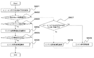
- FIG. 6 is a flow chart showing the flow of control steps in the control block shown in FIG. This flowchart is periodically executed at a predetermined activation timing (for example, every 100 ms).
- step S601 the re-acceleration prediction function 420 of FIG. 4 predicts the acceleration state or deceleration state of the vehicle for each unit step time up to a predetermined time using prediction models shown in FIGS. Store as a continuation counter.
- five prediction results of k1 to k5 are stored as prediction results of 0.2 [s] intervals up to 1.0 [s] ahead.
- step S602 it is determined whether the current operating state of the engine is normal operation or fuel-saving operation.
- step S603 the prediction results of the re-acceleration prediction function 420 at each elapse of the predetermined time estimated in step S601 are evaluated, and the prediction results of k1 to k5 of the prediction state continuation counter 421 are determined. If the prediction results of k1 to k5 are all predictions of deceleration, the process proceeds to step S604. Also, if any of the prediction results k1 to k5 includes prediction of acceleration, the flow chart is terminated and engine control continues with normal operation.
- step S604 preparation for engine fuel-saving operation is started.
- step S605 If it is determined in step S605 that preparation for fuel-saving engine operation has not been completed, the flowchart is terminated, and normal engine control is continued until a state is reached in which fuel-saving engine operation can be performed.
- Step S607 evaluates the prediction state continuation counter 421 of the re-acceleration prediction function 420 when the engine is in fuel-saving operation.
- step S608 If acceleration is predicted, the process proceeds to step S609.
- the vehicle acceleration or deceleration prediction by the re-acceleration prediction function is used.
- the control device 1 (Fig. 4) is a control device for an actuator (internal combustion engine) used for vehicle acceleration.
- the actuator is, for example, an internal combustion engine (engine), a hybrid engine, a motor, or the like.
- the control device 1 (the re-acceleration prediction function 420 in FIG. 4) changes from the first timing (k0) to the second timing (for example, (I) in FIG. 5) at the first timing (for example, k0 in (I) in FIG. Presence/absence of a vehicle acceleration request for each predetermined time period of the period up to k5) of ) is predicted, and the presence or absence of a vehicle acceleration request for each predetermined time period is stored.
- the third timing is the same as the first timing (k0), but it may be another timing (for example, k1 to k4).
- the fourth timing is the same as the first timing (k0), but it may be another timing (for example, k1 to k4).
- the actuator is an internal combustion engine.
- the first state and the second state are combustion states of the internal combustion engine, and the air-fuel ratio in the second state is higher than the air-fuel ratio in the first state.
- the engine speed is lower in the second state than in the first state.
- the EGR rate may be higher or the opening of the waste gate valve may be larger in the second state than in the first state.
- fuel-saving operation can be performed by switching the combustion state of the internal combustion engine from the first state to the second state.
- the EGR rate can be controlled by the throttle valve 102, the EGR valve 122a of the EGR system 122 indicated by the dashed line in FIG. 1, or the like.
- the wastegate valve 123a is one of the parts constituting the turbocharger 123 indicated by the dashed line in FIG. be.
- the control device 1 uses prediction models 1 and 2 (FIGS. 3A and 3B) to predict the presence or absence of a vehicle acceleration request at predetermined time intervals from the first timing to the second timing.
- prediction models 1 and 2 FGS. 3A and 3B
- the control device 1 uses prediction models 1 and 2 (FIGS. 3A and 3B) to predict the presence or absence of a vehicle acceleration request at predetermined time intervals from the first timing to the second timing.
- a first timing using at least one of the following distance from the preceding vehicle, the vehicle speed of the preceding vehicle, the vehicle speed of the own vehicle, and the acceleration of the own vehicle, every predetermined time period from the first timing to the second timing
- Presence or absence of an acceleration request for the vehicle may be predicted. This makes it possible to quantitatively predict the presence or absence of an acceleration request.
- the third timing and the fourth timing described above have the same value, but are independent values. This makes it possible to change the number of presence/absence of acceleration used for prediction between deceleration prediction and acceleration prediction.
- the present embodiment it is possible to prepare for implementing fuel-saving operation before detecting that the load of the engine has become low and shifting to fuel-saving operation, and the implementation time of fuel-saving operation is can be extended to improve fuel efficiency.
- the problem of response delay in air volume control it is possible to avoid deterioration of drivability during control transitions by preparing in advance when the engine returns to normal operation from fuel-saving operation. It is possible.
- the present invention is not limited to the above-described embodiments, and includes various modifications.
- the above-described embodiments have been described in detail in order to explain the present invention in an easy-to-understand manner, and are not necessarily limited to those having all the configurations described.
- part of the configuration of one embodiment can be replaced with the configuration of another embodiment, and the configuration of another embodiment can be added to the configuration of one embodiment.
- an example of control of ⁇ combustion switching is shown as an example of fuel-saving operation of the engine, but it is of course possible to apply it to other engine control in consideration of response delay. For example, when the engine load becomes low during running, the engine is stopped, and when it is predicted that the engine will be accelerated while the engine is stopped, the engine is restarted in consideration of the engine start time.
- various things such as increasing or decreasing the prediction state continuation counter (k1 to k5) according to the request, changing the calculation cycle according to the control responsiveness, etc. method is conceivable.
- each function and each step of the drawings used for explanation may be realized by software or hardware. Some may be implemented in either.
- each block in the block diagram may be included in the same control device, or each block may be arranged in another control device and configured by communication between the control devices.
- a control device for an actuator for reacceleration with an operation delay having at least two operating states comprising a reacceleration prediction function and a prediction state duration counter, wherein the reacceleration prediction function is activated after a predetermined time has elapsed from the current time. It is determined whether or not there is a request for re-acceleration every predetermined time until the re-acceleration request for every predetermined time from the current time calculated by the re-acceleration prediction function until after the elapse of the predetermined time.
- the actuator At the current time, the actuator is operating in state 1, and the prediction up to the farthest point from the current time stored in the prediction state duration counter, after an arbitrary time has passed to the furthest time from the current time, when there is no reacceleration request in all predictions, the operating state of the actuator is changed to state 2.
- the operation state of the actuator is in state 2 at the current time, and the prediction up to the furthest point from the current time stored in the prediction state duration counter occurs after an arbitrary time elapses to the farthest time from the current time, the controller changes the operation state of the actuator to state 1 when there is a request for reacceleration.
- the reacceleration actuator is an internal combustion engine
- the states 1 and 2 are combustion states of the internal combustion engine.
- the re-acceleration prediction function predicts a vehicle, and the re-acceleration prediction function determines whether or not the vehicle will accelerate.
- any one of the current inter-vehicle distance to the preceding vehicle, the current vehicle speed of the preceding vehicle, the current vehicle speed, and the current acceleration of the vehicle is input to the re-acceleration prediction function.
- a control device comprising:
- the air-fuel ratio is set so that when the target air-fuel ratio is compared between the state 1 and the state 2, the air ratio is higher in the state 2 than in the state 1. control device.
- control device in (3), the control device is characterized in that the target engine speed is differentiated between states 1 and 2 of the combustion state of the internal combustion engine.
- the target engine speed is set so that when the target engine speed is compared between states 1 and 2, the engine speed is lower in state 2 than in state 1.
- a control device characterized by:
- Reference Signs List 100 Internal combustion engine 101 Airflow meter 102 Throttle valve 103 Fuel injection valve 104 Fuel pressure sensor 105 Crank angle signal plate 106 Crank angle sensor 107 ECU (engine control unit) DESCRIPTION OF SYMBOLS 108... Water temperature sensor 109... Spark ignition device 110... Valve opening detection sensor 112... Cylinder 113... Piston 114... Fuel supply passage 115... Cam angle sensor 116... Cam shaft 117... Intake valve 118... Cam angle signal plate 119...
- Exhaust pipe 120 Three-way catalyst 121 A/F sensor 122a EGR valve 123a Wastegate valve 411 Requested torque calculator 412 Engine torque calculator 413 ⁇ controller 414 ⁇ switching determination unit 415 Air amount control 416 Fuel Injection control 417 Ignition timing control 420 Re-acceleration prediction function 421 Predicted state continuation counter
Landscapes
- Engineering & Computer Science (AREA)
- Chemical & Material Sciences (AREA)
- Combustion & Propulsion (AREA)
- Mechanical Engineering (AREA)
- General Engineering & Computer Science (AREA)
- Combined Controls Of Internal Combustion Engines (AREA)
- Control Of Vehicle Engines Or Engines For Specific Uses (AREA)
- Electrical Control Of Air Or Fuel Supplied To Internal-Combustion Engine (AREA)
Abstract
À un premier instant, ce dispositif de commande (fonction de prédiction de réaccélération) prédit s'il existe ou non une requête pour accélérer un véhicule à chaque instant prédéterminé d'une période allant du premier instant à un second instant, et stocke s'il existe ou non une requête pour accélérer le véhicule à chaque instant prédéterminé. Le dispositif de commande (ECU) amène l'état de fonctionnement d'un actionneur à passer d'un premier état à un second état d'économie d'énergie dans ladite période de temps lorsque l'état de fonctionnement de l'actionneur au premier instant est le premier état et il est prédit qu'il n'y aura pas de requête d'accélération d'un troisième instant à un second instant dans ladite période de temps.
Priority Applications (2)
| Application Number | Priority Date | Filing Date | Title |
|---|---|---|---|
| DE112022001338.9T DE112022001338T5 (de) | 2021-07-12 | 2022-02-04 | Steuerungsvorrichtung |
| JP2023535085A JP7526896B2 (ja) | 2021-07-12 | 2022-02-04 | 制御装置 |
Applications Claiming Priority (2)
| Application Number | Priority Date | Filing Date | Title |
|---|---|---|---|
| JP2021114813 | 2021-07-12 | ||
| JP2021-114813 | 2021-07-12 |
Publications (1)
| Publication Number | Publication Date |
|---|---|
| WO2023286302A1 true WO2023286302A1 (fr) | 2023-01-19 |
Family
ID=84919204
Family Applications (1)
| Application Number | Title | Priority Date | Filing Date |
|---|---|---|---|
| PCT/JP2022/004442 Ceased WO2023286302A1 (fr) | 2021-07-12 | 2022-02-04 | Dispositif de commande |
Country Status (3)
| Country | Link |
|---|---|
| JP (1) | JP7526896B2 (fr) |
| DE (1) | DE112022001338T5 (fr) |
| WO (1) | WO2023286302A1 (fr) |
Citations (1)
| Publication number | Priority date | Publication date | Assignee | Title |
|---|---|---|---|---|
| JP2004270718A (ja) * | 2003-03-05 | 2004-09-30 | Nissan Motor Co Ltd | 車両用駆動力制御装置 |
-
2022
- 2022-02-04 JP JP2023535085A patent/JP7526896B2/ja active Active
- 2022-02-04 WO PCT/JP2022/004442 patent/WO2023286302A1/fr not_active Ceased
- 2022-02-04 DE DE112022001338.9T patent/DE112022001338T5/de active Pending
Patent Citations (1)
| Publication number | Priority date | Publication date | Assignee | Title |
|---|---|---|---|---|
| JP2004270718A (ja) * | 2003-03-05 | 2004-09-30 | Nissan Motor Co Ltd | 車両用駆動力制御装置 |
Also Published As
| Publication number | Publication date |
|---|---|
| DE112022001338T5 (de) | 2023-12-21 |
| JPWO2023286302A1 (fr) | 2023-01-19 |
| JP7526896B2 (ja) | 2024-08-01 |
Similar Documents
| Publication | Publication Date | Title |
|---|---|---|
| JP3603398B2 (ja) | 内燃機関の制御装置 | |
| US7089913B2 (en) | Compression ignition internal combustion engine | |
| JP5011413B2 (ja) | 筒内直接燃料噴射方式内燃機関の制御装置 | |
| US9181879B2 (en) | Control apparatus for internal combustion engine and control apparatus for vehicle equipped with internal combustion engine | |
| JPWO2002014665A1 (ja) | 圧縮着火式内燃機関 | |
| EP2444641B1 (fr) | Dispositif de commande pour moteur à essence avec injection directe | |
| JP2000008892A (ja) | 電磁駆動式吸気バルブを備えたエンジンの制御装置 | |
| US11136927B2 (en) | Internal combustion engine system | |
| EP2222945B1 (fr) | Dispositif de commande pour moteur à combustion interne | |
| CN101939519B (zh) | 用于车辆内燃机的进气控制装置 | |
| US20030226528A1 (en) | Compression ignition internal combustion engine | |
| JP2011012555A (ja) | 内燃機関の制御装置 | |
| WO2023286302A1 (fr) | Dispositif de commande | |
| WO2005056995A1 (fr) | Unite de commande de moteur | |
| JP2017020449A (ja) | 内燃機関の制御装置 | |
| JP4502030B2 (ja) | 内燃機関の制御装置 | |
| JP5310392B2 (ja) | 内燃機関システムの制御方法及び内燃機関システム | |
| JP2009121263A (ja) | 内燃機関の制御装置 | |
| JP4696987B2 (ja) | 燃料噴射制御装置 | |
| JP2016014354A (ja) | 内燃機関の制御装置 | |
| JP4957033B2 (ja) | 燃料噴射制御装置 | |
| JP2011038477A (ja) | エンジンの制御装置 | |
| JP5834137B2 (ja) | エンジンの制御装置 | |
| JP4877525B2 (ja) | 内燃機関の制御装置 | |
| JP2009057945A (ja) | エンジンの制御装置 |
Legal Events
| Date | Code | Title | Description |
|---|---|---|---|
| 121 | Ep: the epo has been informed by wipo that ep was designated in this application |
Ref document number: 22841652 Country of ref document: EP Kind code of ref document: A1 |
|
| WWE | Wipo information: entry into national phase |
Ref document number: 2023535085 Country of ref document: JP |
|
| WWE | Wipo information: entry into national phase |
Ref document number: 112022001338 Country of ref document: DE |
|
| 122 | Ep: pct application non-entry in european phase |
Ref document number: 22841652 Country of ref document: EP Kind code of ref document: A1 |