WO2024004149A1 - 工作機械、及び、工作機械の軸合わせ方法 - Google Patents
工作機械、及び、工作機械の軸合わせ方法 Download PDFInfo
- Publication number
- WO2024004149A1 WO2024004149A1 PCT/JP2022/026305 JP2022026305W WO2024004149A1 WO 2024004149 A1 WO2024004149 A1 WO 2024004149A1 JP 2022026305 W JP2022026305 W JP 2022026305W WO 2024004149 A1 WO2024004149 A1 WO 2024004149A1
- Authority
- WO
- WIPO (PCT)
- Prior art keywords
- spindle
- main shaft
- axis
- machine tool
- value
- Prior art date
- Legal status (The legal status is an assumption and is not a legal conclusion. Google has not performed a legal analysis and makes no representation as to the accuracy of the status listed.)
- Ceased
Links
Images







Classifications
-
- G—PHYSICS
- G05—CONTROLLING; REGULATING
- G05B—CONTROL OR REGULATING SYSTEMS IN GENERAL; FUNCTIONAL ELEMENTS OF SUCH SYSTEMS; MONITORING OR TESTING ARRANGEMENTS FOR SUCH SYSTEMS OR ELEMENTS
- G05B19/00—Program-control systems
- G05B19/02—Program-control systems electric
- G05B19/18—Numerical control [NC], i.e. automatically operating machines, in particular machine tools, e.g. in a manufacturing environment, so as to execute positioning, movement or co-ordinated operations by means of program data in numerical form
- G05B19/404—Numerical control [NC], i.e. automatically operating machines, in particular machine tools, e.g. in a manufacturing environment, so as to execute positioning, movement or co-ordinated operations by means of program data in numerical form characterised by control arrangements for compensation, e.g. for backlash, overshoot, tool offset, tool wear, temperature, machine construction errors, load, inertia
-
- B—PERFORMING OPERATIONS; TRANSPORTING
- B23—MACHINE TOOLS; METAL-WORKING NOT OTHERWISE PROVIDED FOR
- B23Q—DETAILS, COMPONENTS, OR ACCESSORIES FOR MACHINE TOOLS, e.g. ARRANGEMENTS FOR COPYING OR CONTROLLING; MACHINE TOOLS IN GENERAL CHARACTERISED BY THE CONSTRUCTION OF PARTICULAR DETAILS OR COMPONENTS; COMBINATIONS OR ASSOCIATIONS OF METAL-WORKING MACHINES, NOT DIRECTED TO A PARTICULAR RESULT
- B23Q15/00—Automatic control or regulation of feed movement, cutting velocity or position of tool or work
- B23Q15/007—Automatic control or regulation of feed movement, cutting velocity or position of tool or work while the tool acts upon the workpiece
- B23Q15/12—Adaptive control, i.e. adjusting itself to have a performance which is optimum according to a preassigned criterion
-
- B—PERFORMING OPERATIONS; TRANSPORTING
- B23—MACHINE TOOLS; METAL-WORKING NOT OTHERWISE PROVIDED FOR
- B23Q—DETAILS, COMPONENTS, OR ACCESSORIES FOR MACHINE TOOLS, e.g. ARRANGEMENTS FOR COPYING OR CONTROLLING; MACHINE TOOLS IN GENERAL CHARACTERISED BY THE CONSTRUCTION OF PARTICULAR DETAILS OR COMPONENTS; COMBINATIONS OR ASSOCIATIONS OF METAL-WORKING MACHINES, NOT DIRECTED TO A PARTICULAR RESULT
- B23Q15/00—Automatic control or regulation of feed movement, cutting velocity or position of tool or work
- B23Q15/20—Automatic control or regulation of feed movement, cutting velocity or position of tool or work before or after the tool acts upon the workpiece
- B23Q15/22—Control or regulation of position of tool or workpiece
-
- B—PERFORMING OPERATIONS; TRANSPORTING
- B23—MACHINE TOOLS; METAL-WORKING NOT OTHERWISE PROVIDED FOR
- B23Q—DETAILS, COMPONENTS, OR ACCESSORIES FOR MACHINE TOOLS, e.g. ARRANGEMENTS FOR COPYING OR CONTROLLING; MACHINE TOOLS IN GENERAL CHARACTERISED BY THE CONSTRUCTION OF PARTICULAR DETAILS OR COMPONENTS; COMBINATIONS OR ASSOCIATIONS OF METAL-WORKING MACHINES, NOT DIRECTED TO A PARTICULAR RESULT
- B23Q17/00—Arrangements for observing, indicating or measuring on machine tools
- B23Q17/12—Arrangements for observing, indicating or measuring on machine tools for indicating or measuring vibration
-
- B—PERFORMING OPERATIONS; TRANSPORTING
- B23—MACHINE TOOLS; METAL-WORKING NOT OTHERWISE PROVIDED FOR
- B23B—TURNING; BORING
- B23B25/00—Accessories or auxiliary equipment for turning-machines
- B23B25/06—Measuring, gauging, or adjusting equipment on turning-machines for setting-on, feeding, controlling, or monitoring the cutting tools or work
-
- B—PERFORMING OPERATIONS; TRANSPORTING
- B23—MACHINE TOOLS; METAL-WORKING NOT OTHERWISE PROVIDED FOR
- B23B—TURNING; BORING
- B23B3/00—General-purpose turning-machines or devices, e.g. centre lathes with feed rod and lead screw; Sets of turning-machines
- B23B3/30—Turning-machines with two or more working-spindles, e.g. in fixed arrangement
-
- G—PHYSICS
- G05—CONTROLLING; REGULATING
- G05B—CONTROL OR REGULATING SYSTEMS IN GENERAL; FUNCTIONAL ELEMENTS OF SUCH SYSTEMS; MONITORING OR TESTING ARRANGEMENTS FOR SUCH SYSTEMS OR ELEMENTS
- G05B2219/00—Program-control systems
- G05B2219/30—Nc systems
- G05B2219/37—Measurements
- G05B2219/37434—Measuring vibration of machine or workpiece or tool
-
- G—PHYSICS
- G05—CONTROLLING; REGULATING
- G05B—CONTROL OR REGULATING SYSTEMS IN GENERAL; FUNCTIONAL ELEMENTS OF SUCH SYSTEMS; MONITORING OR TESTING ARRANGEMENTS FOR SUCH SYSTEMS OR ELEMENTS
- G05B2219/00—Program-control systems
- G05B2219/30—Nc systems
- G05B2219/50—Machine tool, machine tool null till machine tool work handling
- G05B2219/50152—Align axis cylinder, tube with rotation axis machine
Definitions
- the present disclosure relates to a machine tool and a method for aligning the axis of the machine tool.
- Machine tools such as NC milling machines and machining centers that process workpieces with tools are known.
- Such machine tools may have a clamp that can be tightened to attach a work or a tool, or may have a main shaft that can rotate with a work or tool attached using a clamp or the like. If there is an abnormality such as chips being caught in the workpiece or the mounting portion of the tool, the machining accuracy of the workpiece may be adversely affected.
- Patent Document 1 describes a machine tool that detects an abnormality based on data regarding vibrations of a clamp that can be tightened in order to mount a workpiece or a tool.
- a machine tool that has a main spindle and a back main spindle on the same axis, and grips one end side and the other end of a workpiece with a clamp that the main spindle has and a clamp that the back main spindle has.
- misalignment also referred to as axis misalignment or misalignment
- Patent Document 2 discloses that an outer diameter measuring device is used to measure the axis of a bar held by a main spindle and the axis of a bar held by a back main spindle in a state facing the main axis, and to measure both of these. There is a description of correcting the misalignment of the axis of the back main spindle with respect to the axis of the main spindle based on measurement data by.
- the purpose of the present disclosure is to more easily align the axis of a machine tool.
- One aspect of the present disclosure is a first spindle that grips one end of the workpiece; a second main shaft that grips the other end of the work; a sensor that detects a physical quantity related to vibration when the first spindle and the second spindle are rotating synchronously with the first spindle and the second spindle gripping the work; a control unit that aligns the first spindle and the second spindle based on the physical quantity; It is a machine tool equipped with
- One of the other aspects of the present disclosure is a first spindle that grips one end of the workpiece; a second main shaft that grips the other end of the work; a sensor that detects a physical quantity related to vibration when the first spindle and the second spindle are rotating synchronously with the first spindle and the second spindle gripping the work; a control unit that aligns the first spindle and the second spindle based on the physical quantity; This is a method for aligning the axis of a machine tool equipped with.
- Another aspect of the present disclosure is a program for causing a computer to execute the above method for aligning the axis of a machine tool, or a storage medium that non-temporarily stores the program.
- axis alignment of a machine tool can be performed more easily.
- FIG. 1 is a diagram showing an example of a machine tool according to an embodiment.
- FIG. 1 is a block diagram schematically showing an example of the configuration of a machine tool according to an embodiment. It is a figure showing an example of the functional composition of a control part. It is a time chart showing detection values of a vibration sensor before and after fastening a workpiece.
- FIG. 6 is a diagram obtained by experimentally determining the dispersion value of the detection values of the vibration sensor when the second principal axis is intentionally shifted with respect to the first principal axis.
- FIG. 6 is a diagram showing an example of a locus of movement of the second main shaft when aligning the first main shaft and the second main shaft.
- FIG. 7 is a diagram showing an example of the dispersion value of the detection value of the vibration sensor when the second main axis is moving along the trajectory shown in FIG. 6;
- FIG. 7 is a diagram showing an example of a trajectory of moving the second main shaft in the direction of the first phase when aligning the first main shaft and the second main shaft.
- FIG. 9 is a diagram showing an example of the variance value of the detection value of the vibration sensor when the second main axis is moving along the trajectory shown in FIG. 8;
- FIG. 7 is a diagram illustrating an example of a locus in which the second principal axis is moved from (X1, Y1) as a starting point when aligning the first principal axis and the second principal axis.
- FIG. 11 is a diagram showing an example of the variance of the detection values of the vibration sensor when the second main axis is moving along the trajectory shown in FIG. 10; 12 is a flowchart showing a flow when aligning the first main axis and the second main axis. It is a flowchart which shows the flow of circle movement processing. 3 is a flowchart showing a flow of linear movement processing.
- FIG. 6 is a diagram obtained experimentally from the range of detection values of the vibration sensor when the second principal axis is intentionally shifted with respect to the first principal axis.
- a machine tool that is one of the aspects of the present disclosure includes a first spindle that grips one end of the workpiece, a second spindle that grips the other end of the workpiece, and a first spindle and a second spindle that grip the workpiece.
- a sensor that detects a physical quantity related to vibration when the first spindle and the second spindle are rotating synchronously in the state, and a control unit that aligns the first spindle and the second spindle based on the physical quantity; Equipped with.
- the control unit performs axis alignment during manufacture of the machine tool or before use.
- the alignment of the first spindle and the second spindle is performed when the first spindle and the second spindle are rotating synchronously with the first spindle and the second spindle gripping the same workpiece.
- "when they are rotating synchronously” may be used as long as the first spindle and the second spindle are rotating synchronously, for example, when the first spindle and the second spindle are rotating synchronously. or when the first main shaft and the second main shaft are rotating when the first main shaft and the second main shaft have a mechanism for synchronous rotation.
- the control unit performs axis alignment based on this vibration.
- the sensor may be any sensor that can detect a physical quantity related to vibrations generated in the first or second main axis, such as a vibration sensor (including an acceleration sensor), a position sensor, or the like.
- FIG. 1 is a diagram showing an example of a machine tool 1 according to the present embodiment.
- the machine tool 1 according to the present embodiment includes a first spindle 11 and a first headstock 12 that rotatably supports the first spindle 11.
- the first main shaft 11 includes a first clamp 13 that can be tightened to attach one end of the workpiece W.
- the machine tool 1 also includes a second spindle 21 on substantially the same axis as the first spindle 11, and a second headstock 22 that rotatably supports the second spindle 21.
- the second main shaft 21 may be a back main shaft.
- the second main shaft 21 includes a second clamp 23 that can be tightened to attach the other end of the workpiece W.
- an adjustment mechanism 24 is provided between the second spindle 21 and the second headstock 22 to move the second spindle 21 relative to the second headstock 22.
- the adjustment mechanism 24 is capable of relatively moving the second main shaft 21 in two axial directions, for example, the X-axis and the Y-axis.
- the adjustment mechanism 24 includes, for example, a gear and an actuator that operates the gear.
- the first headstock 12 and the second headstock 22 are fixed to, for example, a pedestal 100, which is the same structure, so that their relative positions do not change. In FIG. 1, the axial direction of the first main shaft 11 and the second main shaft (the left-right direction in FIG.
- the direction perpendicular to the top surface of the pedestal 100 is defined as the X-axis direction.
- the fastening operation of the workpiece W by the first clamp 13 and the second clamp 23 can be caused by, for example, a clamp actuator (not shown) composed of a cylinder, a piston, or the like.
- a clamp actuator (not shown) composed of a cylinder, a piston, or the like.
- a vibration sensor 25 that measures the vibration of the second main shaft 21 is arranged on the second main shaft 21.
- the vibration sensor 25 may measure the vibration of the second spindle 21 only when aligning the first spindle 11 and the second spindle 21, or the vibration sensor 25 may measure the vibration of the second spindle 21 at all times while the machine tool 1 is in operation.
- the vibration of the main shaft 21 may also be measured.
- the timing of measurement by the vibration sensor 25 can be changed as appropriate.
- the vibration sensor 25 only needs to be placed at a location where the vibration of the second clamp 23 can be measured.
- the vibration sensor 25 may be placed, for example, as close as possible to the second clamp 23.
- an acceleration sensor is used as the vibration sensor 25.
- the acceleration sensor is a sensor that can measure acceleration in one direction, for example, the X-axis direction or the Y-axis direction shown in FIG. 1, but alternatively, it can also be a sensor that can measure acceleration in two or more directions. good.
- the vibration sensor 25 is not limited to an acceleration sensor, and may be, for example, a distance sensor. Further, a plurality of each sensor may be used. Note that in the following, when the detected value of the vibration sensor 25 is referred to, it may be either a voltage that is an output value of the vibration sensor 25, or a value obtained by converting the voltage into acceleration or vibration. This conversion is performed by an axis alignment unit 402, which will be described later.
- the machine tool 1 includes a control section 40.
- the control unit 40 is a computer that controls the machine tool 1.
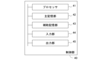
- FIG. 2 is a block diagram schematically showing an example of the configuration of the machine tool 1 according to the present embodiment.
- the control unit 40 has a general computer configuration.
- the control section 40 includes a processor 41 , a main storage section 42 , an auxiliary storage section 43 , an input section 44 , and an output section 45 . These are interconnected by a bus. Sensors such as the vibration sensor 25 are connected to the bus via an interface, and signals from these sensors are input to the control unit 40.
- the bus includes, via an interface, an actuator that rotates the first main shaft 11, an actuator that rotates the second main shaft 21, an actuator that performs the fastening and opening actions of the first clamp 13, and a fastening action of the second clamp 23. , an actuator that performs an opening operation, an adjustment mechanism 24, and the like are connected, and control signals are sent from the control unit 40 to these devices.
- the processor 41 is a CPU (Central Processing Unit), a DSP (Digital Signal Processor), or the like.
- the processor 41 controls the machine tool 1 and performs various information processing operations.
- the main storage unit 42 is a RAM (Random Access Memory), a ROM (Read Only Memory), or the like.
- the auxiliary storage unit 43 is an EPROM (Erasable Programmable ROM), a hard disk drive (HDD), a removable medium, or the like.
- the auxiliary storage unit 43 stores an operating system (OS), various programs, various tables, and the like.
- the processor 41 loads the program stored in the auxiliary storage section 43 into the work area of the main storage section 42 and executes it, and each component etc. is controlled through the execution of this program.
- the control unit 40 realizes a function that meets a predetermined purpose.
- the main storage section 42 and the auxiliary storage section 43 are computer-readable recording media. Note that the control unit 40 may be a single computer or a plurality of computers working together. Further, the information stored in the auxiliary storage section 43 may be stored in the main storage section 42. Further, the information stored in the main storage section 42 may be stored in the auxiliary storage section 43.
- the input unit 44 is a means for accepting input operations performed by the user, and includes, for example, a touch panel, a mouse, a keyboard, a microphone, or the like.
- the output unit 45 is a means for presenting information to the user, and can include, for example, an LCD (Liquid Crystal Display), an EL (Electroluminescence) panel, a speaker, a lamp, and the like. Note that the input section 44 and the output section 45 may be configured as one touch panel display.
- FIG. 3 is a diagram showing an example of the functional configuration of the control unit 40.
- the control unit 40 includes a processing control unit 401 and an axis alignment unit 402 as functional components.
- the processing control unit 401 and the axis alignment unit 402 are functional components provided, for example, by the processor 41 of the control unit 40 executing various programs stored in the auxiliary storage unit 43.
- the machining control unit 401 controls the machine tool 1 when machining the workpiece W.
- the processing control unit 401 fastens the workpiece W using the first clamp 13 and the second clamp 23, rotates the first spindle 11 and the second spindle 21 in synchronization, and further controls the movement of the tool to fasten the workpiece W. For example, cutting.
- Known techniques can be used to control the processing of the workpiece W by the processing control unit 401.
- the axis alignment unit 402 aligns the first spindle 11 and the second spindle 21 (axis alignment) based on the detected value of the vibration sensor 25.
- the axis alignment section 402 performs axis alignment, for example, before the processing control section 401 controls the processing of the workpiece W.
- the relationship between the detection value of the vibration sensor 25 and the axis deviation of the first main shaft 11 and the second main shaft 21 will be explained with reference to FIGS. 4 and 5.
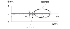
- FIG. 4 is a time chart showing the detected values of the vibration sensor 25 before and after the workpiece W is fastened.
- the horizontal axis in FIG. 4 indicates time, and the vertical axis indicates voltage, which is the output of the vibration sensor 25.
- time is 0 in FIG. 4
- one end side of the work W is clamped only by the first clamp 13, and the first main shaft 11, the work W, and the second main shaft 21 are rotating synchronously. Thereafter, the other end side of the workpiece W is clamped by the second clamp 23.
- the vibration generated at that time is detected by the vibration sensor 25.
- the vibration caused by the clamp is indicated by "clamp" in FIG. After that, the first main shaft 11 and the second main shaft 21 are rotating synchronously with both ends of the workpiece W being gripped by the first main shaft 11 and the second main shaft 21.
- FIG. 5 is a diagram in which the variance values of the detection values of the vibration sensor 25 when the second main shaft 21 is intentionally shifted with respect to the first main shaft 11 are experimentally determined.
- the horizontal axis in FIG. 5 indicates the relative shift of the second main axis 21 with respect to the first main axis 11 in the X-axis direction.
- the X-axis according to FIG. 5 corresponds to the X-axis defined in FIG. 1. Note that there is no deviation in the Y-axis direction.
- the dispersion value in FIG. 5 is the dispersion value of the values detected by the vibration sensor 25 during the period indicated by "measurement period” in FIG. 4.
- the measurement period in FIG. 4 is a period after the vibration caused by the clamp has become sufficiently small, and is a period sufficient to calculate the dispersion value. Note that in the following, when the term "dispersion” is used, it refers to the dispersion of the detected values of the vibration sensor 25.
- this phenomenon is utilized to align the first main shaft 11 and the second main shaft 21. That is, the first main shaft 11 and the second main shaft 21 are aligned by moving the second main shaft 21 in a direction in which the dispersion value of the detection values of the vibration sensor 25 becomes smaller.
- the alignment unit 402 aligns the first spindle 11 and the second spindle 21 while gripping the same workpiece W with both the first spindle 11 and the second spindle 21. 21 are rotated in a predetermined direction at a predetermined rotational speed (that is, rotated synchronously). Moreover, the axis alignment unit 402 performs axis alignment after the vibrations generated by fastening the workpiece W have become sufficiently small so as not to be affected by the vibrations. Note that axis alignment can be performed only once when manufacturing the machine tool 1, or each time the machine tool 1 is started, or each time the workpiece W is fastened.
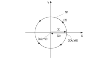
- FIG. 6 is a diagram showing an example of a locus of movement of the second main shaft 21 when aligning the first main shaft 11 and the second main shaft 21.
- the X-axis and Y-axis in FIG. 6 correspond to the X-axis and Y-axis in FIG. 1.
- the coordinates of the origin which is the starting point of the second main axis 21, are indicated by (X0, Y0).
- This origin is the position of the central axis of the second main shaft 21 when the second main shaft 21 performs the fastening operation of the workpiece W.
- the axis alignment unit 402 moves the second main shaft 21 along a circle S1 centered on the origin (X0, Y0).
- the diameter of the circle S1 can be set to an arbitrary value that is equal to or less than the maximum value of the misalignment between the first main shaft 11 and the second main shaft 21 due to manufacturing tolerances, for example. In other words, even if axis misalignment occurs between the first spindle 11 and the second spindle 21, it is considered that the axis misalignment occurs within the range of manufacturing tolerances, so move the second spindle 21 within this range. Find the position where the axes match.
- the axis alignment unit 402 performs the following processing during axis alignment.
- the following (1) to (3) correspond to the arrows (1) to (3) shown in FIG.
- the alignment unit 402 generates a command to move the second main shaft 21 in the X-axis direction to (XA, Y0).
- the detected value of the vibration sensor 25 at this time is not used.
- the position (XA, Y0) is the intersection of the X axis and the circle S1. Note that the position (XA, Y0) or the straight radius of the circle S1 is stored in the auxiliary storage section 43 in advance.
- the axis alignment unit 402 sends the generated command to the adjustment mechanism 24, and the adjustment mechanism 24 moves the second main shaft 21 based on this command.
- the alignment section 402 stops the second main shaft 21.
- the current position of the second main shaft 21 may be detected by a sensor, for example, or may be calculated based on the amount of operation of the adjustment mechanism 24.
- the axis alignment unit 402 generates a command to move the second main shaft 21 along the circle S1.
- the second main shaft 21 is moved counterclockwise, but is not limited thereto, and may be moved clockwise.
- the detection value of the vibration sensor 25 is obtained, for example, at each predetermined phase centered on the origin (X0, Y0).
- the alignment unit 402 stops the second main shaft 21 over a measurement period at every predetermined phase, and acquires the detection value of the vibration sensor 25 over the measurement period. Therefore, the alignment unit 402 generates and sends to the adjustment mechanism 24 a command to move the second main shaft 21 along the circle S1 and a command to stop the second main shaft 21 over a measurement period for each predetermined phase. Then, the adjustment mechanism 24 moves the second main shaft 21 based on this command.
- the measurement period is set in advance as a period during which the dispersion value corresponding to the axis misalignment can be calculated with high accuracy.
- the alignment unit 402 stores the detection value of the vibration sensor 25 acquired over the measurement period for each predetermined phase in the auxiliary storage unit 43 in association with the phase centered on the origin (X0, Y0). . Furthermore, based on the detection values of the vibration sensor 25 acquired over the measurement period, a variance value of the detection values of the vibration sensor 25 is calculated, and this variance value is linked to the phase centered on the origin (X0, Y0). and stores it in the auxiliary storage section 43.
- the predetermined phase may be set based on, for example, the time required for alignment and the accuracy of alignment. The accuracy of alignment increases as the predetermined phase becomes smaller, but the time required for alignment becomes longer, so the user may set it based on whether time or accuracy is prioritized. For example, it may be possible to input a predetermined phase from the input section 44.
- the alignment unit 402 stops the detection of vibration by the vibration sensor 25, and moves the second main shaft 21 to the origin (X0, Y0). Generate a command to move.
- the alignment unit 402 sends the generated command to the adjustment mechanism 24, and based on this command, the adjustment mechanism 24 moves the second main shaft 21 to the origin (X0, Y0).
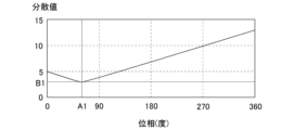
- FIG. 7 is a diagram showing an example of the variance of the detected values of the vibration sensor 25 when the second main shaft 21 is moving along the trajectory shown in FIG. 6.
- the phase on the horizontal axis indicates the phase centered on the origin (X0, Y0), with the phase when the second main shaft 21 is located at the position (XA, Y0) being 0.
- the dispersion value decreases as the phase increases from 0, and for example, at the phase indicated by A1, the dispersion value becomes the minimum value indicated by B1. Further, as the phase becomes larger than A1, the dispersion value also becomes larger.
- the phase indicated by A1 will also be referred to as a first phase A1.
- the position where the variance value is the smallest on the circle S1 corresponds to the first target position according to the present disclosure.
- the dispersion value is the minimum at the first phase A1. Then, by moving the second main axis 21 from the origin (X0, Y0) in the direction of the first phase A1, the dispersion value can be reduced. That is, it is considered that the deviation between the first main shaft 11 and the second main shaft 21 becomes smaller.
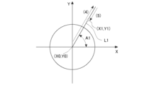
- FIG. 8 is a diagram showing an example of a trajectory in which the second main shaft 21 is moved in the direction of the first phase A1 when aligning the first main shaft 11 and the second main shaft 21.
- the origin (X0, Y0) in FIG. 8 is the same position as the origin (X0, Y0) shown in FIG.
- the axis alignment unit 402 moves the second main shaft 21 along the straight line L1 extending from the origin (X0, Y0) in the direction of the first phase A1. Therefore, the alignment unit 402 performs the following processing.
- the following (4)-(5) correspond to the arrows (4)-(5) shown in FIG.
- the axis alignment unit 402 generates a command to move the second main shaft 21 along the straight line L1 in a direction away from the origin (X0, Y0) on the straight line L1.
- the detection value of the vibration sensor 25 is obtained, for example, at every predetermined distance from the origin (X0, Y0).
- the alignment unit 402 stops the second main shaft 21 at predetermined distance intervals over the measurement period, and acquires the detection value of the vibration sensor 25 over the measurement period. Therefore, the alignment unit 402 generates a command to move the second main shaft 21 along the straight line L1 and a command to stop the second main shaft 21 for a measurement period every predetermined distance, and sends the command to the adjustment mechanism 24. Then, the adjustment mechanism 24 moves the second main shaft 21 based on this command.
- the axis alignment unit 402 associates the detection value of the vibration sensor 25 acquired over the measurement period with the distance from the origin (X0, Y0) for each predetermined distance and stores it in the auxiliary storage unit 43. Furthermore, based on the detection values of the vibration sensor 25 acquired over the measurement period, a variance value of the detection values of the vibration sensor 25 is calculated, and this variance value is linked to the distance from the origin (X0, Y0). The information is stored in the auxiliary storage section 43.
- the predetermined distance may be set based on, for example, the time required for alignment and the accuracy of alignment. As the predetermined distance becomes smaller, the accuracy of axis alignment increases, but the time required for axis alignment increases, so the user may set it based on whether priority is given to time or accuracy. For example, it may be possible to input a predetermined distance from the input unit 44.
- the axis alignment unit 402 determines a second origin (X1, Y1) where the dispersion value is the minimum, and moves the second principal axis 21 to the second origin. Generate a command to move to (X1, Y1).
- the alignment unit 402 compares the dispersion value stored in the auxiliary storage unit 43 with the dispersion values before and after it to find the dispersion value B2 at which the decreasing trend changes to the increasing trend, and calculates the dispersion value B2 corresponding to the dispersion value B2. Find the distance A2 from the origin (X0, Y0).
- This position (X1, Y1) is hereinafter also referred to as the second origin (X1, Y1).
- the second origin (X1, Y1) is a position when moved by a distance A2 in the direction of the first phase A1 with respect to the origin (X0, Y0).
- the alignment unit 402 sends the generated command to the adjustment mechanism 24, and based on this command, the adjustment mechanism 24 moves the second main shaft 21 to the second origin (X1, Y1). Note that the position where the dispersion value is the smallest on the straight line L1 corresponds to the second target position according to the present disclosure.
- FIG. 9 is a diagram showing an example of the variance of the detected values of the vibration sensor 25 when the second main shaft 21 is moving along the trajectory shown in FIG. 8.
- the distance on the horizontal axis is the distance from the origin (X0, Y0).
- (4)-(5) shown in FIG. 9 correspond to (4)-(5) shown in FIG.
- the dispersion value decreases as the distance increases from 0, and when the distance is A2, the dispersion value becomes the minimum value indicated by B2. Furthermore, the larger the distance is than A2, the larger the dispersion value becomes. In this way, when the distance is A2, the dispersion value becomes the minimum at B2.
- the second origin (X1, Y1) is a position moved from the origin (X0, Y0) by the distance where the variance value is the smallest in the direction of the phase where the variance value of the detected values of the vibration sensor 25 is the smallest. be.
- Such a second origin (X1, Y1) has a smaller variance value of the detection value of the vibration sensor 25 than the origin (X0, Y0). In this way, it is possible to search for a position where the variance value of the detection values of the vibration sensor 25 is smaller.
- the alignment unit 402 executes the control in (1) to (5) above again using the second origin (X1, Y1) as a starting point. In this manner, by repeatedly performing the above control, it is possible to determine the position of the second main shaft 21 where the variance value of the detected values of the vibration sensor 25 becomes smaller.
- FIG. 10 is a diagram showing an example of a trajectory in which the second spindle 21 is moved from (X1, Y1) as a starting point when aligning the first spindle 11 and the second spindle 21.
- the coordinates of the starting point of the second main axis 21 are the second origin (X1, Y1).
- the second limit (X1, Y1) becomes the origin of the X'Y' coordinate system.
- the second origin (X1, Y1) which is the starting point in FIG. 10, is the same position as the second origin (X1, Y1) in FIG.
- the alignment unit 402 moves the second main shaft 21 along a circle S2 centered on the second origin (X1, Y1). Circle S2 has the same diameter as circle S1 shown in FIG. Alternatively, the diameter of the circle S2 may be smaller than the diameter of the circle S1.
- the axis alignment unit 402 performs the following process.
- the following (6) to (8) correspond to the arrows (6) to (8) shown in FIG.
- the alignment unit 402 generates a command to move the second main shaft 21 in the X'-axis direction to the position (X1+XA, Y1). The detected value of the vibration sensor 25 at this time is not used.
- the alignment unit 402 sends the generated command to the adjustment mechanism 24, and the adjustment mechanism 24 moves the second main shaft 21 based on this command.
- the axis alignment unit 402 generates a command to move the second main shaft 21 along the circle S2.
- the detected value of the vibration sensor 25 is acquired, for example, at every predetermined phase centered on the second origin (X1, Y1).
- the alignment unit 402 stops the second main shaft 21 over a measurement period at every predetermined phase, and acquires the detection value of the vibration sensor 25 over the measurement period. Therefore, the alignment unit 402 generates and sends to the adjustment mechanism 24 a command to move the second main shaft 21 along the circle S2 and a command to stop the second main shaft 21 over a measurement period for each predetermined phase. Then, the adjustment mechanism 24 moves the second main shaft 21 based on this command.
- the alignment unit 402 associates the detection value of the vibration sensor 25 acquired over the measurement period with the phase centered on the second origin (X1, Y1) for each predetermined phase, and stores it in the auxiliary storage unit 43. Make me remember. Furthermore, based on the detection values of the vibration sensor 25 acquired over the measurement period, a variance value of the detection values of the vibration sensor 25 is calculated, and this variance value is calculated as the phase centered on the second origin (X1, Y1). The information is linked and stored in the auxiliary storage unit 43.
- the predetermined phase is the same as the predetermined phase explained in FIG. However, alternatively, a phase different from the predetermined phase shown in FIG. 6 may be employed.
- the alignment unit 402 stops the detection of vibration by the vibration sensor 25, and moves the second main shaft to the second origin (X1, Y1). A command to move 21 is generated.
- the alignment unit 402 sends the generated command to the adjustment mechanism 24, and based on this command, the adjustment mechanism 24 moves the second main shaft 21 to the second origin (X1, Y1).
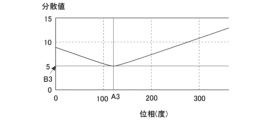
- FIG. 11 is a diagram showing an example of the variance of the detected values of the vibration sensor 25 when the second main shaft 21 is moving along the trajectory shown in FIG. 10.
- the phase on the horizontal axis indicates the phase centered on the second origin (X1, Y1), with the phase when the second main shaft 21 is located at the position (X1+XA, Y1) being 0.
- the dispersion value decreases as the phase increases from 0, and for example, at the phase indicated by A3, the dispersion value becomes the minimum value indicated by B3. Further, as the phase becomes larger than A3, the dispersion value also becomes larger.
- the phase indicated by A3 will also be referred to as a second phase A3.
- the position where the variance value is the smallest on the circle S2 also corresponds to the first target position according to the present disclosure.
- the dispersion value becomes the minimum at the second phase A3. Then, by moving the second main axis 21 from the second origin (X1, Y1) in the direction of the second phase A3, the dispersion value can be reduced. That is, the misalignment between the first main shaft 11 and the second main shaft 21 can be reduced. In this case, it is possible to search for a position where the variance value is even smaller by executing a process similar to that described with reference to FIGS. 8 and 9. At this time, the same process is repeatedly executed by replacing the X'Y' axis with the XY axis and proceeding with the process.
- the minimum variance value B3 shown in FIG. 11 is greater than or equal to the minimum variance value B2 shown in FIG. 9. Therefore, if the minimum value B3 of the dispersion value shown in FIG. 11 is greater than or equal to the minimum value B2 of the dispersion value shown in FIG. 9, it is considered that there is no need to move the position of the second main shaft 21 any further. Therefore, in this embodiment, if the minimum value B3 of the variance values shown in FIG. 11 is greater than or equal to the minimum value B2 of the variance values shown in FIG. It is determined that alignment of the first main shaft 11 and the second main shaft 21 has been completed.
- the second principal axis 21 is moved along the circle S1 to find the phase where the variance value is the minimum, and the second principal axis 21 is moved along the straight line L1 to find the position where the variance value is the minimum.
- the alignment unit 402 updates the second origin (X1, Y1) as the origin of the second spindle 21. Note that at this point, the second main spindle 21 is located at the second origin (X1, Y1), so the processing control by the processing control unit 401 is started while the position of the second main spindle 21 remains unchanged.
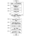
- FIG. 12 is a flowchart showing a flow when aligning the first spindle 11 and the second spindle 21.
- This routine is executed before the machining control unit 401 performs machining control in the machine tool 1.
- the execution may be triggered by the user inputting to the input unit 44 to control processing.
- the process may be executed based on the user's input to the input unit 44 when the machine tool 1 is manufactured or when the user starts the machine tool 1.
- the process may be executed at predetermined time intervals or every predetermined number of times the machine tool 1 is started.
- step S101 the alignment unit 402 executes a fastening process.
- the fastening process is a process in which the first spindle 11 grips one end of the workpiece W, the second spindle 21 grips the other end of the workpiece W, and rotates them synchronously.
- the first spindle 11 is rotated at a predetermined rotational speed while one end side of the workpiece W is clamped by the first spindle 11.
- the second main shaft 21 rotating synchronously with the first main shaft 11, the second main shaft 21 clamps the other end side of the workpiece W.
- step S102 the axis alignment unit 402 determines whether a predetermined time has elapsed since the second main shaft 21 and the workpiece W were fastened together.
- the predetermined time here is, for example, the time until vibrations generated by fastening the workpiece W become sufficiently small. If an affirmative determination is made in step S102, the process advances to step S103, and if a negative determination is made, the process of step S102 is executed again.
- step S103 the axis alignment unit 402 acquires the origin of the second main axis 21.
- the origin here is the position of the second spindle 21 at the time when the fastening is completed in step S101, the origin (X0, Y0) set in step S310 described later, or the origin updated in step S106 in the previous routine. This is the origin (X0, Y0).
- step S104 the axis alignment unit 402 performs circular movement processing.
- the circular movement process is a process of moving the second main axis 21 along the circle S1 and acquiring the dispersion values of the detected values of the vibration sensor 25 at a plurality of locations.
- FIG. 13 is a flowchart showing the flow of the circular movement process.
- the process shown in FIG. 13 is a subroutine executed in step S104.
- step S201 the axis alignment unit 402 moves the second main shaft 21 to the circle S1.
- the alignment unit 402 generates a command to move the second main shaft 21 to the circle S1 and sends it to the adjustment mechanism 24.
- step S202 the alignment unit 402 moves the second main shaft 21 on the circle S1 by a predetermined phase.
- the alignment unit 402 generates a command and sends it to the adjustment mechanism 24 so that the second spindle 21 moves by a predetermined phase on the circle S1 with respect to the second headstock 22.
- step S203 the alignment unit 402 detects vibration by acquiring the detection value of the vibration sensor 25 over the measurement period.
- the detected value of the vibration sensor 25 is stored in the auxiliary storage unit 43 in association with the phase at that time.
- step S204 the alignment unit 402 calculates a variance value based on the detected value obtained in step S203.
- step S205 the alignment unit 402 stores the calculated dispersion value in the auxiliary storage unit 43 in association with the phase at that time.
- step S206 the alignment unit 402 determines whether the second main shaft 21 has gone around the circle S1.
- the axis alignment unit 402 determines whether the current position of the second main shaft 21 matches the position after moving in step S201. If an affirmative determination is made in step S206, the process advances to step S207, and if a negative determination is made, the process returns to step S202.
- step S207 the alignment unit 402 extracts the minimum value B1 from among the variance values stored in step S205. Then, in step S208, the alignment unit 402 acquires the phase A1 corresponding to the minimum value B1 of the variance values extracted in step S207 from the data stored in step S205.
- step S209 the axis alignment unit 402 moves the second main shaft 21 to the origin (X0, Y0), which is the starting point.
- the alignment unit 402 generates a command to move the second main shaft 21 to the origin (X0, Y0) and sends it to the adjustment mechanism 24.
- the process of step S209 may be executed in parallel with the processes of step S207 and step S208, or the process of step S209 may be executed before the processes of step S207 and step S208. Good too.
- the process in step S209 is completed, the process returns to the routine shown in FIG. 12 and proceeds to step S105.
- step S105 the alignment unit 402 determines whether the minimum value B1 of the variance values acquired in step S104 is greater than or equal to the minimum value B2 of the variance values acquired in the previous step S108. Note that B2 is not acquired the first time this routine is executed. Therefore, the initial value of B2 is stored in the auxiliary storage section 43 in advance as a value that will result in an affirmative determination in step S105 when the axes are aligned. Alternatively, the initial value of B2 may be set to a sufficiently large value so that a negative determination is always made in step S105.
- a step of calculating a variance value at the origin may be added between step S102 and step S103, and this variance value at the origin may be used as the initial value of B2. If an affirmative determination is made in step S105, the process proceeds to step S106, and if a negative determination is made, the process proceeds to step S108, where linear movement processing is executed.
- FIG. 14 is a flowchart showing the flow of linear movement processing.
- the process shown in FIG. 14 is a subroutine executed in step S108.
- the linear movement process corresponds to the process for finding B2, which is the minimum value of the variance values shown in FIG.
- step S301 the alignment unit 402 moves the second main shaft 21 by a predetermined distance in the direction of phase A1 corresponding to the minimum value B1 of the dispersion values obtained in the immediately preceding step S208.
- the alignment unit 402 generates a command and sends it to the adjustment mechanism 24 so that the second spindle 21 moves a predetermined distance from the origin in the direction of phase A1 with respect to the second headstock 22.
- step S302 the alignment unit 402 detects vibration by acquiring the detection value of the vibration sensor 25 over the measurement period.
- the detected value of the vibration sensor 25 is stored in the auxiliary storage unit 43 in association with the distance from the origin at that time.
- step S303 the alignment unit 402 calculates a variance value based on the detected value acquired in step S302.
- step S304 the alignment unit 402 stores the calculated dispersion value in the auxiliary storage unit 43 in association with the distance from the origin at that time.
- step S305 the alignment unit 402 determines whether the variance value has changed from a decreasing trend to an increasing trend.
- the alignment unit 402 determines that, for example, the variance value stored in the previous step S304 is smaller than the variance value stored in the previous step S304, and that the variance value in the current step is smaller than the variance value stored in the previous step S304. If the variance value stored in S304 is larger, it is determined that the variance value has changed from a decreasing trend to an increasing trend. Alternatively, if there is no change from the variance value stored in the previous step S304, or if there is a change, it is sufficiently small, it may be determined that the variance value has changed from a decreasing trend to an increasing trend. good.
- step S305 If an affirmative determination is made in step S305, the process advances to step S306, and if a negative determination is made, the process returns to step S301.
- step S309 the axis alignment unit 402 moves the second main shaft 21 to the second origin (X1, Y1).
- the alignment unit 402 generates a command to move the second main shaft 21 to the second origin (X1, Y1) and sends it to the adjustment mechanism 24.
- step S310 the alignment unit 402 updates the origin so that the second origin (X1, Y1) becomes the new origin (X0, Y0) of the second main shaft 21.
- step S105 the second principal axis 21 is moved along the circle S1 to obtain the phase A1 where the variance value is the minimum, and the second principal axis 21 is moved in the direction where the variance value is the minimum.
- the process of obtaining the position (X1, Y1) where the variance value of the detected values of the vibration sensor 25 is the minimum while moving the vibration sensor 25 is alternately and repeatedly performed.
- step S106 the axis alignment unit 402 updates the current position of the second spindle 21 as the origin of the second spindle 21 when processing the workpiece W.
- the origin of the second main axis 21 is stored in the auxiliary storage section 43.
- step S107 the alignment unit 402 resets the minimum value B2 of the variance values. As a result, the minimum value B2 of the variance value returns to the initial value.
- the alignment of the first main shaft 11 and the second main shaft 21 can be performed based on the dispersion value of the detection value of the vibration sensor 25. That is, by adjusting the relative position of the first spindle 11 and the second spindle 21 to a position where the variance value of the detection values of the vibration sensor 25 is smaller, alignment can be performed more quickly and more accurately. can.
- the second main axis 21 is moved along the circle S1 and the straight line L1, and the dispersion value of the detection value of the vibration sensor 25 is acquired.
- a mesh is generated around the second principal axis 21, and the variance value of the detection value of the vibration sensor 25 is obtained at each intersection of the mesh, and the position where the variance value is the smallest is determined as It is determined that the axes of the first main shaft 11 and the second main shaft 21 are aligned.
- the size of the mesh is related to the accuracy of axis alignment, and the smaller the mesh, the higher the accuracy of axis alignment.
- the size of the mesh may be determined depending on which is given priority: the accuracy of axis alignment or the time required for axis alignment.
- first set the mesh large move the second principal axis 21 to the position where the variance value is the smallest, and then generate a smaller mesh around that position to find the position where the variance value is the smallest. You can ask for it.
- the positions where the axes of the first principal axis 11 and the second principal axis 21 match may be narrowed down by repeatedly executing the process of gradually reducing the size of the mesh and calculating the dispersion value.
- the first principal axis 11 and the second principal axis 21 can also be aligned by generating a mesh in this way and calculating the variance of the detected values of the vibration sensor 25 at each intersection of the mesh.
- axis alignment is performed using the dispersion value of the detection values of the vibration sensor 25, but the sensor is not limited to this, and any sensor capable of detecting a physical quantity correlated with vibration may be used.
- a displacement meter, an ammeter, an AE (Acoustic Emission) sensor, or a microphone may be used.
- the second main axis 21 is moved along the circle S1, but instead of this, it may be moved along the sides of a polygon centered on the origin. Then, vibrations may be detected by the vibration sensor 25 at each of the vertices of the polygon, and further the variance value may be calculated.
- variance that is, the average of the squares of the deviations from the average value
- the present invention is not limited to this, and other values indicating the degree of dispersion can also be used.
- standard deviation root mean square, range (difference between maximum value and minimum value), or amplitude of vibration may be used instead of variance.
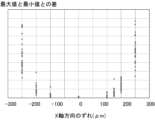
- FIG. 15 is a diagram that experimentally determined the range of detection values (the difference between the maximum value and the minimum value) of the vibration sensor 25 when the second main shaft 21 is intentionally shifted with respect to the first main shaft 11. .
- the horizontal axis in FIG. 15 indicates the relative shift of the second main axis 21 with respect to the first main axis 11 in the X-axis direction.
- the X-axis in FIG. 15 corresponds to the X-axis defined in FIG. 1. Note that there is no deviation in the Y-axis direction.
- the range of detected values is obtained multiple times and plotted for the same amount of deviation.
- the range of detected values in FIG. 15 is the difference between the maximum value and the minimum value of the values detected by the vibration sensor 25 during the period indicated by "measurement period" in FIG. 4.
- the range of the detected value can be used to align the first principal axis 11 and the second principal axis 21. That is, the first main shaft 11 and the second main shaft 21 can be aligned by moving the second main shaft 21 in a direction in which the range of detection values of the vibration sensor 25 becomes smaller.
Landscapes
- Engineering & Computer Science (AREA)
- Mechanical Engineering (AREA)
- Human Computer Interaction (AREA)
- Manufacturing & Machinery (AREA)
- Physics & Mathematics (AREA)
- General Physics & Mathematics (AREA)
- Automation & Control Theory (AREA)
- Automatic Control Of Machine Tools (AREA)
- Numerical Control (AREA)
Abstract
Description
ワークの一端側を把持する第一主軸と、
前記ワークの他端側を把持する第二主軸と、
前記第一主軸及び前記第二主軸が前記ワークを把持した状態で、前記第一主軸及び前記第二主軸が同期回転しているときの振動に関連する物理量を検出するセンサと、
前記物理量に基づいて前記第一主軸と前記第二主軸との軸合わせを行う制御部と、
を備える工作機械である。
ワークの一端側を把持する第一主軸と、
前記ワークの他端側を把持する第二主軸と、
前記第一主軸及び前記第二主軸が前記ワークを把持した状態で、前記第一主軸及び前記第二主軸が同期回転しているときの振動に関連する物理量を検出するセンサと、
前記物理量に基づいて前記第一主軸と前記第二主軸との軸合わせを行う制御部と、
を備える工作機械の軸合わせ方法である。
図1は、本実施形態に係る工作機械1の一例を示した図である。図1に示すように、本実施形態に係る工作機械1は、第一主軸11と、この第一主軸11を回転可能に支持する第一主軸台12とを備えている。第一主軸11は、ワークWの一端側を装着するために締結動作可能な第一クランプ13を備えている。また、工作機械1は、第一主軸11と略同一の軸線上に第二主軸21と、この第二主軸21を回転可能に支持する第二主軸台22とを備えている。第二主軸21は、背面主軸としてもよい。第二主軸21は、ワークWの他端側を装着するために締結動作可能な第二クランプ23を備えている。また、第二主軸21と第二主軸台22との間には、第二主軸21を第二主軸台22に対して相対的に移動させる調整機構24が備わる。調整機構24は、例えば、X軸及びY軸の二軸方向に第二主軸21を相対移動可能である。調整機構24は、例えば、歯車とその歯車を作動させるアクチュエータとを含んで構成される。第一主軸台12と第二主軸台22とは、相対位置が変化しないように、例えば同一の構造物である台座100に固定されている。図1において、第一主軸11及び第二主軸の軸方向(図1の左右方向)をZ軸方向とし、Z軸と直交し台座100の上面と平行な方向(図1の上下方向)をY軸方向とし、台座100の上面と直交する方向(図1の前後方向)をX軸方向とする。
第1実施形態では第二主軸21を円S1及び直線L1に沿って移動させつつ、振動センサ25の検出値の分散値を取得している。一方、本第2実施形態では、第二主軸21の周りにメッシュを生成し、そのメッシュの各交点において振動センサ25の検出値の分散値を取得して、分散値が最も小さい位置が、第一主軸11及び第二主軸21の軸が合っている位置であると判定する。
第1実施形態及び第2実施形態では、振動センサ25の検出値の分散値を利用して軸合わせを行っているが、センサはこれに限らず、振動と相関する物理量を検出可能なセンサであればよい。例えば、変位計、電流計、AE(Acoustic Emission)センサ、または、マイクロフォンでもよい。
11 第一主軸
12 第一主軸台
13 第一クランプ
21 第二主軸
22 第二主軸台
23 第二クランプ
24 調整機構
25 振動センサ
40 制御部
41 プロセッサ
42 主記憶部
43 補助記憶部
44 入力部
45 出力部
Claims (9)
- ワークの一端側を把持する第一主軸と、
前記ワークの他端側を把持する第二主軸と、
前記第一主軸及び前記第二主軸が前記ワークを把持した状態で、前記第一主軸及び前記第二主軸が同期回転しているときの振動に関連する物理量を検出するセンサと、
前記物理量に基づいて前記第一主軸と前記第二主軸との軸合わせを行う制御部と、
を備える工作機械。 - 前記制御部は、
前記第一主軸と前記第二主軸との相対位置をずらした第一の複数の位置において夫々、前記センサで前記物理量を検出し、
前記第一の複数の位置のうち前記物理量が最も小さい位置を前記第一主軸と前記第二主軸との第一目標位置とする、
請求項1に記載の工作機械。 - 前記第一の複数の位置を、同一円上にずらした位置とする、
請求項2に記載の工作機械。 - 前記制御部は、
前記円の中心から前記第一目標位置の方向に前記第一主軸と前記第二主軸との相対位置をずらした第二の複数の位置において夫々、前記センサで前記物理量を検出し、
前記第二の複数の位置のうち前記物理量が最も小さい位置を前記第一主軸と前記第二主軸との第二目標位置とする、
請求項3に記載の工作機械。 - 前記制御部は、
前記第二目標位置を前記円の中心として、前記第一の複数の位置において夫々、前記センサで前記物理量を検出し、前記第一の複数の位置のうち前記物理量が最も小さい位置を取得することで前記第一目標位置を更新し、
更新後の前記第一目標位置の方向の前記第二の複数の位置において夫々、前記センサで前記物理量を検出し、前記第二の複数の位置のうち前記物理量が最も小さい位置を取得することで前記第二目標位置を更新する、
ことを繰り返し行う、
請求項4に記載の工作機械。 - 前記制御部は、前記第一目標位置における前記物理量が、直前の前記第二目標位置における前記物理量以上である場合に、直前の前記第二目標位置が、前記第一主軸と前記第二主軸との軸が合っている位置であると判定する、
請求項5に記載の工作機械。 - 前記物理量は、前記センサの検出値の分散値である、
請求項2から6の何れか一項に記載の工作機械。 - 前記制御部は、前記第一主軸と前記第二主軸との軸ずれの公差の範囲内に前記第一の複数の位置を設定する、
請求項2から7の何れか1項に記載の工作機械。 - ワークの一端側を把持する第一主軸と、
前記ワークの他端側を把持する第二主軸と、
前記第一主軸及び前記第二主軸が前記ワークを把持した状態で、前記第一主軸及び前記第二主軸が同期回転しているときの振動に関連する物理量を検出するセンサと、
前記物理量に基づいて前記第一主軸と前記第二主軸との軸合わせを行う制御部と、
を備える工作機械の軸合わせ方法。
Priority Applications (5)
| Application Number | Priority Date | Filing Date | Title |
|---|---|---|---|
| US18/876,311 US20250360588A1 (en) | 2022-06-30 | 2022-06-30 | Machine tool, and machine tool alignment method |
| CN202280097071.0A CN119365284A (zh) | 2022-06-30 | 2022-06-30 | 机床和机床的轴对齐方法 |
| PCT/JP2022/026305 WO2024004149A1 (ja) | 2022-06-30 | 2022-06-30 | 工作機械、及び、工作機械の軸合わせ方法 |
| EP22949422.4A EP4549059A4 (en) | 2022-06-30 | 2022-06-30 | MACHINE TOOL, AND METHOD FOR ALIGNING MACHINE TOOLS |
| KR1020247040878A KR20250002809A (ko) | 2022-06-30 | 2022-06-30 | 공작 기계 및 공작 기계의 축맞춤 방법 |
Applications Claiming Priority (1)
| Application Number | Priority Date | Filing Date | Title |
|---|---|---|---|
| PCT/JP2022/026305 WO2024004149A1 (ja) | 2022-06-30 | 2022-06-30 | 工作機械、及び、工作機械の軸合わせ方法 |
Publications (1)
| Publication Number | Publication Date |
|---|---|
| WO2024004149A1 true WO2024004149A1 (ja) | 2024-01-04 |
Family
ID=89382463
Family Applications (1)
| Application Number | Title | Priority Date | Filing Date |
|---|---|---|---|
| PCT/JP2022/026305 Ceased WO2024004149A1 (ja) | 2022-06-30 | 2022-06-30 | 工作機械、及び、工作機械の軸合わせ方法 |
Country Status (5)
| Country | Link |
|---|---|
| US (1) | US20250360588A1 (ja) |
| EP (1) | EP4549059A4 (ja) |
| KR (1) | KR20250002809A (ja) |
| CN (1) | CN119365284A (ja) |
| WO (1) | WO2024004149A1 (ja) |
Citations (8)
| Publication number | Priority date | Publication date | Assignee | Title |
|---|---|---|---|---|
| JPH01309647A (ja) | 1988-06-07 | 1989-12-14 | Horiken:Kk | 穀類の連続処理装置 |
| JPH03190601A (ja) * | 1989-12-15 | 1991-08-20 | Fanuc Ltd | ワーク交換方法 |
| JPH11309647A (ja) * | 1998-04-28 | 1999-11-09 | Star Micronics Co Ltd | Nc自動旋盤の芯出し方法 |
| JPH11320340A (ja) * | 1998-05-01 | 1999-11-24 | Citizen Watch Co Ltd | 自動旋盤の心出し用測定装置及び心出し方法 |
| JP2019198924A (ja) * | 2018-05-16 | 2019-11-21 | 有限会社高峰精機 | ワークの芯出し方法及びチャック爪 |
| JP2020055051A (ja) | 2018-09-28 | 2020-04-09 | シチズン時計株式会社 | 工作機械及びその作動方法 |
| JP2020082263A (ja) * | 2018-11-22 | 2020-06-04 | スター精密株式会社 | 旋盤 |
| WO2020209134A1 (ja) * | 2019-04-11 | 2020-10-15 | シチズン時計株式会社 | 工作機械及び検知方法 |
Family Cites Families (2)
| Publication number | Priority date | Publication date | Assignee | Title |
|---|---|---|---|---|
| DE102015012818A1 (de) * | 2015-10-05 | 2017-04-06 | Liebherr-Verzahntechnik Gmbh | Bearbeitungskopf mit Wuchteinrichtung |
| KR20230028251A (ko) * | 2020-06-30 | 2023-02-28 | 시티즌 도케이 가부시키가이샤 | 공작 기계, 공작 기계의 제어 방법 |
-
2022
- 2022-06-30 CN CN202280097071.0A patent/CN119365284A/zh active Pending
- 2022-06-30 WO PCT/JP2022/026305 patent/WO2024004149A1/ja not_active Ceased
- 2022-06-30 US US18/876,311 patent/US20250360588A1/en active Pending
- 2022-06-30 EP EP22949422.4A patent/EP4549059A4/en active Pending
- 2022-06-30 KR KR1020247040878A patent/KR20250002809A/ko active Pending
Patent Citations (8)
| Publication number | Priority date | Publication date | Assignee | Title |
|---|---|---|---|---|
| JPH01309647A (ja) | 1988-06-07 | 1989-12-14 | Horiken:Kk | 穀類の連続処理装置 |
| JPH03190601A (ja) * | 1989-12-15 | 1991-08-20 | Fanuc Ltd | ワーク交換方法 |
| JPH11309647A (ja) * | 1998-04-28 | 1999-11-09 | Star Micronics Co Ltd | Nc自動旋盤の芯出し方法 |
| JPH11320340A (ja) * | 1998-05-01 | 1999-11-24 | Citizen Watch Co Ltd | 自動旋盤の心出し用測定装置及び心出し方法 |
| JP2019198924A (ja) * | 2018-05-16 | 2019-11-21 | 有限会社高峰精機 | ワークの芯出し方法及びチャック爪 |
| JP2020055051A (ja) | 2018-09-28 | 2020-04-09 | シチズン時計株式会社 | 工作機械及びその作動方法 |
| JP2020082263A (ja) * | 2018-11-22 | 2020-06-04 | スター精密株式会社 | 旋盤 |
| WO2020209134A1 (ja) * | 2019-04-11 | 2020-10-15 | シチズン時計株式会社 | 工作機械及び検知方法 |
Non-Patent Citations (1)
| Title |
|---|
| See also references of EP4549059A4 |
Also Published As
| Publication number | Publication date |
|---|---|
| US20250360588A1 (en) | 2025-11-27 |
| EP4549059A1 (en) | 2025-05-07 |
| CN119365284A (zh) | 2025-01-24 |
| EP4549059A4 (en) | 2026-04-22 |
| KR20250002809A (ko) | 2025-01-07 |
Similar Documents
| Publication | Publication Date | Title |
|---|---|---|
| JP5793200B2 (ja) | 工作機械の切削力検出装置、切削力検出方法、加工異常検出方法、および加工条件制御システム | |
| CN102029546B (zh) | 振动抑制装置 | |
| JP7053526B2 (ja) | 主軸振動測定システム、主軸振動測定方法、およびプログラム | |
| WO2013150905A1 (ja) | 切削加工システム及び方法 | |
| JP2015109023A (ja) | 多軸工作機械の幾何誤差同定方法及び多軸工作機械 | |
| JP2003530230A (ja) | 産業ロボットの経路補正 | |
| CN102441817A (zh) | 工作历史管理方法以及工作历史管理装置 | |
| Celikag et al. | Chatter suppression in robotic milling by control of configuration dependent dynamics | |
| Diez et al. | Dynamic analysis of a piezoelectric system to compensate for workpiece deformations in flexible milling | |
| KR102840795B1 (ko) | 공작기계 주축의 동심도 보정 장치 및 보정 방법 | |
| JP7514800B2 (ja) | 工作機械、及び、工作機械の軸合わせ方法 | |
| Suzuki et al. | Effect of cross transfer function on chatter stability in plunge cutting | |
| CN108647413B (zh) | 一种微细表面位置误差与稳定性综合预测方法 | |
| TW202019613A (zh) | 工作機械及其作動方法 | |
| TWI917668B (zh) | 工具機及工具機的軸對準方法 | |
| JP2003005813A (ja) | オービットボーリングの制御方法 | |
| KR910007053B1 (ko) | 회전기계와 같은 공작기계를 제어하는 방법과 시스템 | |
| KR20250002809A (ko) | 공작 기계 및 공작 기계의 축맞춤 방법 | |
| Zhao et al. | Measurement‐Based Modal Analysis and Stability Prediction on Turn‐Milling of Hollow Turbine Blade | |
| TW202402445A (zh) | 工具機及工具機的軸對準方法 | |
| JP6978457B2 (ja) | 情報処理装置および情報処理方法 | |
| Dai et al. | An updated model of stability prediction in five-axis ball-end milling | |
| JP6985673B1 (ja) | 加工プログラム生成方法および加工プログラム生成装置 | |
| JP7328474B1 (ja) | 数値制御装置 | |
| JP2011177813A (ja) | 制御装置及び制御方法 |
Legal Events
| Date | Code | Title | Description |
|---|---|---|---|
| 121 | Ep: the epo has been informed by wipo that ep was designated in this application |
Ref document number: 22949422 Country of ref document: EP Kind code of ref document: A1 |
|
| ENP | Entry into the national phase |
Ref document number: 20247040878 Country of ref document: KR Kind code of ref document: A |
|
| WWE | Wipo information: entry into national phase |
Ref document number: 1020247040878 Country of ref document: KR |
|
| WWE | Wipo information: entry into national phase |
Ref document number: 202280097071.0 Country of ref document: CN |
|
| WWE | Wipo information: entry into national phase |
Ref document number: 18876311 Country of ref document: US |
|
| WWP | Wipo information: published in national office |
Ref document number: 202280097071.0 Country of ref document: CN |
|
| WWE | Wipo information: entry into national phase |
Ref document number: 2022949422 Country of ref document: EP |
|
| NENP | Non-entry into the national phase |
Ref country code: DE |
|
| ENP | Entry into the national phase |
Ref document number: 2022949422 Country of ref document: EP Effective date: 20250130 |
|
| WWP | Wipo information: published in national office |
Ref document number: 2022949422 Country of ref document: EP |
|
| NENP | Non-entry into the national phase |
Ref country code: JP |
|
| WWP | Wipo information: published in national office |
Ref document number: 18876311 Country of ref document: US |