WO2024004366A1 - Dispositif de commande sans fil, système de communication, programme et procédé de commande pour dispositif de commande sans fil - Google Patents
Dispositif de commande sans fil, système de communication, programme et procédé de commande pour dispositif de commande sans fil Download PDFInfo
- Publication number
- WO2024004366A1 WO2024004366A1 PCT/JP2023/016599 JP2023016599W WO2024004366A1 WO 2024004366 A1 WO2024004366 A1 WO 2024004366A1 JP 2023016599 W JP2023016599 W JP 2023016599W WO 2024004366 A1 WO2024004366 A1 WO 2024004366A1
- Authority
- WO
- WIPO (PCT)
- Prior art keywords
- noma
- signal
- reference position
- control device
- wireless
- Prior art date
- Legal status (The legal status is an assumption and is not a legal conclusion. Google has not performed a legal analysis and makes no representation as to the accuracy of the status listed.)
- Ceased
Links
Images


Classifications
-
- H—ELECTRICITY
- H04—ELECTRIC COMMUNICATION TECHNIQUE
- H04J—MULTIPLEX COMMUNICATION
- H04J99/00—Subject matter not provided for in other groups of this subclass
-
- H—ELECTRICITY
- H04—ELECTRIC COMMUNICATION TECHNIQUE
- H04W—WIRELESS COMMUNICATION NETWORKS
- H04W72/00—Local resource management
- H04W72/04—Wireless resource allocation
- H04W72/044—Wireless resource allocation based on the type of the allocated resource
-
- H—ELECTRICITY
- H04—ELECTRIC COMMUNICATION TECHNIQUE
- H04W—WIRELESS COMMUNICATION NETWORKS
- H04W84/00—Network topologies
- H04W84/02—Hierarchically pre-organised networks, e.g. paging networks, cellular networks, WLAN [Wireless Local Area Network] or WLL [Wireless Local Loop]
- H04W84/10—Small scale networks; Flat hierarchical networks
- H04W84/12—WLAN [Wireless Local Area Networks]
Definitions
- the present technology relates to a wireless control device.
- the present invention relates to a wireless control device that performs multiplexing, a communication system, a program, and a method of controlling the wireless control device.
- a delay may occur due to transmission standby.
- NOMA Non-Orthogonal Multiple Access
- a wireless station multiplexes another signal while allowing some interference to occur while transmitting a signal to another wireless station. It may happen.
- a wireless station has been proposed that applies a random power offset in a subframe in which NOMA is used (see, for example, Patent Document 1).
- This technology was created in view of this situation, and its purpose is to suppress interference in a radio control device that performs multiplexing using the NOMA method.
- the present technology has been developed to solve the above-mentioned problems, and its first aspect is the frequency domain or
- the wireless control device includes a control unit that determines a transmission position in at least one time domain based on a random value. This brings about the effect of suppressing interference.
- the control unit acquires reference position information indicating a predetermined reference position in at least one of a frequency domain and a time domain, which is included in a signal transmitted from another wireless device.
- the transmission position may be determined based on the reference position information. This brings about the effect that the transmission position is determined based on the reference position.
- control unit may determine, as the transmission position, a position shifted from the reference position by an amount based on the random value along at least one of a time axis and a frequency axis. good. This brings about the effect of suppressing interference.
- control unit may determine, as the transmission position, a position shifted by an amount based on a random value within a predetermined range along at least one of the time axis and the frequency axis. good. This results in the effect that a random position is determined within a predetermined range.
- the signal may include range information indicating the range. This brings about the effect that a random position is specified within a predetermined range indicating range information.
- the signal may include information indicating that the communication mode is the NOMA communication mode. This brings about the effect that NOMA type communication is started.
- the NOMA target signal may include information indicating that the signal is allowed to be multiplexed by the NOMA method. This brings about the effect that multiplexing is performed using the NOMA method.
- the signal may include step information indicating a unit to be shifted from the reference position. This brings about the effect that step information is extracted from the broadcast signal.
- the NOMA target signal may include step information indicating a unit of shift from the reference position. This brings about the effect that step information is extracted from the NOMA signal.
- the other wireless device may be a base station, and the signal may be a response signal of the base station to a predetermined polling signal. This brings about the effect that step information can be obtained even if there is a hidden terminal.
- the reference position may include a reference position common to all communication terminals connected to the base station. This brings about the effect that a position shifted from a common reference position is obtained.
- the reference position may include a reference position common to a predetermined number of communication terminals within a predetermined group. As a result, within a group, a position shifted from the reference position of the group is obtained.
- the reference position may include a reference position individually assigned to a predetermined communication terminal. This brings about the effect that a position shifted from an individual reference position is acquired for each communication terminal.
- the reference position may include a reference position assigned to a hidden terminal to which the NOMA target signal does not reach. This brings about an effect that the hidden terminal acquires a position shifted from the individual reference position.
- a second aspect of the present technology also provides a first communication terminal that transmits a predetermined NOMA signal, and at least one of the frequency domain and time domain of the NOMA signal multiplexed with the NOMA signal by the NOMA method.
- the second communication terminal includes a control unit that determines a transmission position within an area based on a random value. This brings about the effect of suppressing interference within the wireless communication system.
- FIG. 1 is a diagram illustrating a configuration example of a wireless communication system in a first embodiment of the present technology.
- FIG. 2 is a block diagram illustrating a configuration example of a communication terminal in a first embodiment of the present technology.
- FIG. 2 is a sequence diagram illustrating an example of a communication method of the wireless communication system according to the first embodiment of the present technology.
- FIG. 3 is a diagram for explaining interference countermeasures in the first embodiment of the present technology.
- FIG. 2 is a diagram illustrating an example of the structure of a frame within a broadcast signal from a base station in the first embodiment of the present technology.
- FIG. 3 is a diagram showing an example of a reference position within a notification signal in the first embodiment of the present technology.
- FIG. 3 is a diagram illustrating an example of the structure of a frame within a NOMA target signal from a NOMA target terminal in the first embodiment of the present technology. It is a figure showing one example of frame composition in the 1st modification of the 1st embodiment of this art.
- FIG. 7 is a diagram illustrating an example of a frame configuration in a second modified example of the first embodiment of the present technology.
- FIG. 3 is a sequence diagram illustrating an example of a communication method of a wireless communication system according to a second embodiment of the present technology.
- FIG. 7 is a diagram illustrating a configuration example of a notification signal in a second embodiment of the present technology.
- FIG. 3 is a diagram illustrating an example of the structure of a frame within a NOMA target signal from a NOMA target terminal in the first embodiment of the present technology. It is a figure showing one example of frame composition in the 1st modification of the 1st embodiment of this art.
- FIG. 7 is a diagram illustrating an example of a frame
- FIG. 2 is a block diagram showing a configuration example of a wireless communication device used as a first application example.
- FIG. 2 is a block diagram showing a configuration example of a wireless communication module of a wireless communication device used as a first application example.
- FIG. 3 is a block diagram showing a configuration example of a wireless communication device used as a second application example.
- FIG. 7 is a block diagram showing a configuration example of a wireless communication device used as a third application example.
- FIG. 7 is a block diagram showing a configuration example of a wireless communication device used as a fourth application example.
- First embodiment (example of shifting from the reference position) 2.
- Second embodiment (example of shifting from a reference position using step information in a response signal to a polling signal) 3.
- First application example (example where a module other than the wireless communication module is installed in the wireless communication device) 4.
- Second application example (example where the wireless communication device is applied to a smartphone) 5.
- Third application example (example where wireless communication device is applied to in-vehicle device) 6.
- Fourth application example (example where the wireless communication device is applied to a wireless AP with a wired communication interface)
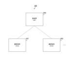
- FIG. 1 is a diagram illustrating a configuration example of a wireless communication system 100 in an embodiment of the present technology.
- This wireless communication system 100 includes a base station 200 and one or more communication terminals such as communication terminals 201 and 202.
- This wireless communication system 100 is also called BSS (Basic Service Set).
- the base station 200 is a wireless station that performs wireless communication with communication terminals connected to itself.
- the base station 200 is also called an access point or a base unit.
- the IEEE802.11 standard is used as the communication standard. For example, the next generation standard after IEEE802.11be is used. Further, a signal from the communication terminal to the base station 200 is an uplink signal, and a signal from the base station 200 to the communication terminal is a downlink signal.
- the communication terminals 201 and 202 are wireless stations that are connected to the base station 200 through association processing or the like and perform wireless communication with the base station 200. These communication terminals are also called slave devices. Further, it is assumed that while a certain communication terminal is transmitting an uplink signal, another communication terminal can multiplex another uplink signal onto that signal using the NOMA method. This NOMA multiplexing is used, for example, when transmitting signals requiring low delay.
- the uplink signal that allows multiplexing using the NOMA method will be referred to as a "NOMA target signal”, and the communication terminal that is the source thereof will be referred to as a "NOMA target terminal”.
- the uplink signal multiplexed with the NOMA signal by the NOMA method is referred to as a "NOMA signal”
- the communication terminal that is the source thereof is referred to as a "NOMA terminal”.
- FIG. 2 is a block diagram showing a configuration example of the communication terminal 201 in the first embodiment of the present technology.
- This communication terminal 201 includes a control section 211, a power supply section 212, and a communication section 220.
- the communication unit 220 includes a radio control device 221, a data processing unit 222, a modulation/demodulation unit 223, a signal processing unit 224, a channel estimation unit 225, and one or more antennas such as antennas 213 and 214.
- the communication unit 220 includes one or more wireless interface units such as wireless interface units 226 and 227, and one or more amplifier units such as amplifier units 228 and 229. An amplifier section is connected to each of the wireless interface sections, and an antenna is connected to each of the amplifier sections. Note that the configurations of base station 200 and communication terminal 202 are similar to communication terminal 201.
- the control unit 211 controls the entire communication terminal 201.
- the power supply unit 212 is configured with a battery or a fixed power supply, and supplies power to the communication terminal 201. At least a portion of the control unit 211 and the communication unit 220 can be realized by LSI (Large Scale Integration).
- a wireless control device 221 is used to exchange signals between each section within the communication section 220 and the control section 211.
- the radio control device 221 also schedules packets in the data processing section 222, sets parameters for the radio interface section and the amplifier section, and controls transmission power.
- the radio control device 221 determines the transmission position of the NOMA signal, Obtain from that reference position.
- the reference position is a position used as a reference when acquiring the transmission position of the NOMA signal in at least one of the frequency domain and the time domain.
- the radio control device 221 controls the radio interface unit 226 and the like to transmit the NOMA signal from its transmission position.
- the communication terminal 201 can multiplex signals using the NOMA method at a transmission position determined by the terminal itself based on the reference position information.
- the radio control device 221 transmits a NOMA target signal upon receiving a downlink signal including the reference position. Details of the sequence when multiplexing using the NOMA method will be described later.
- the data processing unit 222 performs processing in the MAC (Media Access Control) layer. During transmission, the data processing unit 222 generates a packet by adding a MAC header, an error detection code, etc. to upper layer data such as the LLC (Logical Link Control) layer from the radio control device 221. The data processing section 222 then supplies the processed packet to the modulation/demodulation section 223.
- MAC Media Access Control
- LLC Logical Link Control
- the data processing unit 222 performs MAC header analysis, packet error detection, reorder processing, etc. on the packet from the modulation/demodulation unit 223, and sends the processed data via the radio control device 221. and then supply it to the upper layer.
- the modulation/demodulation section 223 performs modulation and demodulation. At the time of transmission, the modulation/demodulation section 223 performs encoding, interleaving, and modulation on the packet from the data processing section 222 based on the coding and modulation method set by the radio control device 221, and generates a data symbol stream. do. Then, the modulation/demodulation section 223 supplies the data symbol stream to the signal processing section 224.
- the modulation/demodulation section 223 performs decoding, deinterleaving, and demodulation on the data symbol stream from the signal processing section 224 corresponding to that during transmission, and supplies the processed packets to the data processing section 222. .
- the signal processing unit 224 performs various signal processing. During transmission, this signal processing unit 224 performs signal processing for spatial separation on the input from the modulation/demodulation unit 223 as necessary, and transmits the obtained one or more transmission symbol streams to the wireless interface unit 226 or 227.
- the signal processing unit 224 performs signal processing on the received symbol streams from the wireless interface units 226 and 227, performs spatial decomposition of the stream as necessary, and supplies the stream to the modulation/demodulation unit 223.
- the signal processing unit 224 performs interference cancellation processing on the input from the wireless interface unit and extracts a desired signal from the superimposed signals.
- Complex channel gain information from the channel estimator 225 is used in this interference cancellation process.
- the channel estimation unit 225 calculates complex channel gain information of the transmission path from the preamble part and the training signal part of the input signal from each wireless interface part.
- the calculated complex channel gain information is supplied to the modulation/demodulation section 223 and the signal processing section 224 and used for spatial processing.
- the wireless interface units 226 and 227 mutually convert analog signals and digital signals. During transmission, these wireless interface units convert the digital signal from the signal processing unit 224 into an analog signal, perform filtering and up-conversion, and send the signal to the corresponding amplifier unit.
- the wireless interface section down-converts the analog signal at the time of reception, converts it into a digital signal, and supplies it to the channel estimation section 225 and the signal processing section 224.
- the amplifier sections 228 and 229 are for amplifying analog signals. During transmission, these amplifier sections amplify analog signals from the corresponding wireless interface sections to a predetermined power level, and supply the amplified signals to the corresponding antennas. Further, during reception, the amplifier section amplifies the analog signal from the corresponding antenna to a predetermined power and supplies it to the corresponding wireless interface section.
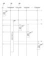
- FIG. 3 is a sequence diagram illustrating an example of a communication method of the wireless communication system 100 according to the first embodiment of the present technology.
- the sequence shown in the figure is started when performing multiplex communication using the NOMA method without prior arrangement of transmission timing (in other words, asynchronous).
- NOMA mode The mode in which this asynchronous multiplex communication is performed.
- the base station 200 transmits a notification signal 501 notifying the transition to NOMA mode to each of the communication terminals under its control.
- this broadcast signal 501 can also be transmitted by the base station 200 in response to a request from a communication terminal.
- the notification signal 501 includes information indicating a transition to NOMA mode, information indicating a reference position, and step information indicating a unit for shifting from the reference position in at least one of the frequency domain and the time domain. including. The specific contents and storage location of this information will be described later.
- the BSS including the base station 200 shifts to NOMA mode.
- the notification signal 501 may be configured not to include step information. Further, a plurality of reference positions can be stored in the notification signal 501.
- a communication terminal transmits an uplink signal (ie, a NOMA target signal) that allows multiplexing using the NOMA method when one or more of the following conditions is satisfied.
- an uplink signal ie, a NOMA target signal
- the NOMA signal is longer than a certain length.
- the NOMA signal is not a signal that requires high reliability.
- the NOMA terminal can transmit an uplink signal (that is, a NOMA signal) that is multiplexed with the NOMA target signal using the NOMA method.
- a NOMA signal that is, a NOMA signal
- the communication terminal 201 functions as the NOMA terminal STA#0, and N (N is an integer) communication terminals including the communication terminal 202 function as the NOMA terminals STA#1 to STA#N.
- the NOMA target terminal STA#0 transmits the NOMA target signal 505 to the base station 200 and each of the NOMA terminals.
- This NOMA target signal 505 includes information indicating that it is a NOMA target signal.
- the NOMA target terminal STA#0 stores the changed step information in the NOMA target signal 505 and transmits it. be able to. Furthermore, if the broadcast signal 501 does not include step information, the NOMA target terminal STA#0 stores the step information in the NOMA target signal 505 and transmits it.
- the broadcast signal 501 includes step information, and the NOMA target signal 505 does not include step information.
- the notification signal 501 includes the step information before the change, and the NOMA target signal 505 includes the step information after the change.
- the broadcast signal 501 does not include step information, and the NOMA signal 505 includes step information.
- the NOMA terminal STA#0 when transmitting the NOMA signal 505, the NOMA terminal STA#0 performs processing to increase interference resistance for the signal portion of the NOMA signal 505 that may be multiplexed. is desirable.
- processing for increasing interference resistance include the following three.
- (Process 1) For signal portions that may be multiplexed, set MCS (Modulation and Channel Coding Scheme) lower than for other portions.
- (Process 2) Invalidate some RUs (Resource Units) of the signal portion that may be multiplexed so that they are not used.
- (Process 3) Duplicate the same data within a signal portion that may be multiplexed.
- the NOMA target terminal STA#0 may perform only one of these processes, or may perform a combination of two or more.
- each NOMA terminal obtains the transmission position of the NOMA signal from the reference position and step information. For example, the NOMA terminal generates a pseudo-random number, and calculates, as the transmission position, a position shifted from the reference position in the frequency/time domain by a value obtained by multiplying the pseudo-random number by the unit indicated by the step information. Pseudo-random numbers are generated by, for example, a linear congruential method or a linear feedback shift register.
- T send T ref +R ⁇ T step ...Formula 1
- the method for calculating the transmission position is not limited to Formula 1.
- the NOMA terminal can use the remaining BO (BackOff) counter number or an index calculated from an AID (Association Identifier) as a pseudorandom number instead of a pseudorandom number generated by a linear congruential method or the like.
- the index is calculated, for example, from the remainder obtained by dividing the AID by the number of communication terminals.
- the transmission position on the frequency axis is also calculated by the same calculation. Thereby, a position shifted by a random value within a predetermined range along at least one of the time axis and the frequency axis is specified as the transmission position.
- the broadcast signal may include range information indicating the range of the transmission position or the range of the pseudorandom number R.
- NOMA terminal STA#1 calculates timing T11 from timing T10 using Equation 1, and transmits NOMA signal 506 to base station 200 over a transmission period after that timing.
- NOMA terminal STA#2 calculates timing T12 from timing T10 using Equation 1, and transmits NOMA signal 507 to base station 200 after that timing.
- NOMA terminal STA#N calculates timing T21 from timing T20 using Equation 1, and transmits NOMA signal 508 to base station 200 over the transmission period after that timing. For example, if timing T10 has passed by the time NOMA terminal STA#N generates the transmission signal, timing T20 is used in Equation 1.
- the base station 200 When the base station 200 receives the NOMA signal, it performs interference cancellation processing on the NOMA signal and the NOMA signals from each NOMA terminal, detects each signal, and performs decoding processing.
- each NOMA terminal transmits a NOMA signal from the same transmission position, even if a random power offset is applied, more signals than expected will be multiplexed when multiplexing using the NOMA method. Interference may become large. In this case, the receiving side may not be able to decode the signal, and there is a risk that retransmission may occur due to reception failure, increasing delay.
- each NOMA terminal acquires a transmission position shifted from the reference position and transmits the NOMA signal, so when multiplexing asynchronously, more signals than expected are multiplexed. It is possible to suppress interference from increasing. Thereby, it is possible to suppress the occurrence of retransmission due to reception failure. Furthermore, by performing communication asynchronously, it is possible to reduce signaling overhead for determining signal transmission timing.
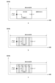
- FIG. 4 is a diagram for explaining interference countermeasures in the first embodiment of the present technology. As described above, it is desirable that the NOMA target terminal STA#0 performs processing to increase the interference resistance of the signal portion of the NOMA target signal 505 that may be multiplexed.
- the vertical axes of a, b, and c indicate frequency, and the horizontal axis indicates time. Moreover, a black circle indicates a reference position. Moreover, the arrow indicates the direction of shift.
- the rectangular portion in which "NOMA" is written indicates the NOMA signal. A portion surrounded by a dotted line indicates a signal portion where the NOMA signal may be multiplexed.
- the NOMA target terminal can execute process 1 of lowering the MCS for a signal portion that may be multiplexed than for other portions.
- the NOMA target terminal can also set the MCS lower than the value defined in the communication standard for a signal portion that may be multiplexed.
- the NOMA target terminal can also perform process 2 of invalidating some RUs of the signal portion that may be multiplexed so as not to use them.
- the diagonally shaded portion b in the figure indicates an invalidated RU.
- the NOMA target terminal can also perform process 3 of duplicating the same data within a signal portion that may be multiplexed.
- the gray area c in the figure is data that is a copy of the white area on the left side.
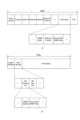
- FIG. 5 is a diagram illustrating a configuration example of a frame within a broadcast signal from base station 200 in the first embodiment of the present technology.
- the broadcast signal includes a PPDU (PLCP Protocol Data Unit), and the PPDU (ie, PHY frame) includes an MPDU (MAC Protocol Data Unit).
- This MPDU ie, MAC frame
- This MPDU includes a "Frame Control” field, a "Duration” field, an "Address” field, a "Sequence Control” field, a frame body, a "FCS (Frame Check Sequence)” field, and the like.
- the format of the MPDU depends on the type of communication standard, and may further include an "HT (High Throughput) Control" field.
- the frame body of the MPDU in the broadcast signal includes a "NOMA Mode” field, a "Reference Position” field, and a "NOMA STEP” field.
- the "NOMA Mode” field stores information indicating that the wireless communication system 100 has shifted to the NOMA mode. This information may be managed with a 1-bit flag, or may be defined separately from other NOMA communications. Further, a part (at least one or two of these) of "NOMA Mode", “Reference Position", and "NOMA STEP" and the rest may be transmitted in separate MPDUs or PPDUs.
- the reference position is stored in the “Reference Position” field. For example, the beginning of the packet, the midamble, or the beginning of the signal (ie, information in the payload) is used as the reference position.
- the "NOMA STEP" field stores step information indicating the unit for shifting from the reference position.
- step information is defined by a fixed time length and a fixed frequency shift length.
- the fixed time length information for example, information specifying one of a plurality of predefined time lengths or a multiple of a predefined minimum fixed time length is written.
- parameters (coefficients, etc.) used for calculation of the fixed time length from the packet length are described.
- information on the frequency shift length information specifying the size of a frequency block consisting of a plurality of predefined subcarriers and a multiple of a predefined minimum frequency block are described.
- FIG. 6 is a diagram illustrating an example of a reference position within a notification signal according to the first embodiment of the present technology. At least one of the following three types can be stored in the "Reference Position" field.
- (Type 1) A reference position common to all communication terminals connected to a base station.
- (Type 2) A reference position common to a predetermined number of communication terminals within a predetermined group.
- (Type 3) A reference position individually assigned to a predetermined communication terminal.
- a indicates a configuration in which only one type is stored
- "Reference Position #1" and “Reference Position #2” indicate reference positions common to all communication terminals. Only one common reference position or two or more of these common reference positions may be stored.
- b in the figure indicates a configuration in which two types are stored, and "Reference Position for Group#1" and “Reference Position for Group#2" indicate a common reference position for a predetermined number of communication terminals in each group. . There may be one group, or two or more groups.
- c indicates a configuration in which three types are stored, and "Reference Position for STA#1" indicates a reference position individually assigned to communication terminal STA#1. It is also possible to individually assign a reference position to each of two or more communication terminals.
- each communication terminal When multiple types of reference positions are stored, each communication terminal, for example, if there is a reference position individually assigned to itself, uses that reference position with the highest priority. Further, if each communication terminal has a reference position for the group to which it belongs, it uses it with priority over a reference position common to all communication terminals.
- FIG. 7 is a diagram illustrating an example of step information in a notification signal in the first embodiment of the present technology.
- the "NOMA STEP" field in the broadcast signal includes a "Time Domain NOMA STEP” field and a "Freq Domain NOMA STEP” field.
- the "Time Domain NOMA STEP” field stores information indicating the unit (fixed time length, etc.) to be shifted from the reference position in the time domain.
- the "Freq Domain NOMA STEP” field stores information indicating the unit (frequency shift length, etc.) to be shifted from the reference position in the frequency domain.
- FIG. 8 is a diagram illustrating an example of the structure of a frame in a NOMA target signal from a NOMA target terminal in the first embodiment of the present technology.
- the NOMA signal includes a PPDU (PHY frame), and the PPDU includes a "Legacy Preamble” field, a "Post BE SIG” field, and a frame body.
- the "Legacy Preamble” field stores the preamble signal used in the previous communication standard.
- the "Post BE SIG” field stores various information regarding the signal (SIGNAL) stored in the frame body, and its format is determined by the next generation communication standard after IEEE802.11be.
- the "Post BE SIG” field includes the "MU Common info” field and the "MU User Info” field.
- the “MU Common info” field stores information common to each communication terminal in the wireless communication system 100. This field includes, for example, a "NOMA Indicator” field and a "NOMA Step” field.
- the "NOMA Indicator” field stores information indicating that the signal is a signal that allows multiplexing using the NOMA method (that is, a signal subject to NOMA).
- the "NOMA Step” field is provided as necessary. For example, when the NOMA target terminal changes step information, the changed step information is stored in the "NOMA Step” field. Furthermore, if the broadcast signal from base station 200 does not include step information, the NOMA target terminal generates step information and stores it in the "NOMA Step” field in the NOMA target signal. Note that "NOMA Indicator” and “NOMA Step” may be transmitted in separate MPDUs or PPDUs.
- the value indicated by the step information may have to be changed depending on the signal length of the NOMA signal and the allowable amount of interference based on SINR (Signal to Interference plus Noise Ratio). Step information is stored in .
- the NOMA terminal acquires the transmission position from the reference position and transmits the NOMA signal from the transmission position, more signals than expected are multiplexed. It is possible to suppress interference from increasing. Thereby, it is possible to suppress the occurrence of retransmission due to reception failure.
- the communication terminal shifts from the reference position in both the frequency domain and the time domain, but it is also possible to shift in only one of them.
- the wireless communication system 100 according to the first modification of the first embodiment differs from the first embodiment in that the position is shifted from the reference position only in the time domain.
- FIG. 9 is a diagram illustrating an example of the structure of a frame in the first modification of the first embodiment of the present technology.
- a indicates an example of the configuration of a MAC frame within a broadcast signal from the base station 200.
- b in the same figure shows an example of the structure of a PHY frame within the NOMA target signal from the NOMA target terminal.
- the MAC frame in the broadcast signal includes a "Time Domain NOMA STEP” field, but does not include a "Freq Domain NOMA STEP” field.
- the PHY frame within the NOMA target signal similarly includes the "Time Domain NOMA STEP” field, but does not include the "Freq Domain NOMA STEP” field.
- the communication terminal shifts from the reference position in both the frequency domain and the time domain, but it is also possible to shift from the reference position in only one of them.
- the wireless communication system 100 according to the second modification of the first embodiment differs from the first embodiment in that it is shifted from the reference position only in the frequency domain.
- FIG. 10 is a diagram illustrating a configuration example of a frame in a second modification of the first embodiment of the present technology.
- a indicates an example of the configuration of a MAC frame within a broadcast signal from the base station 200.
- b in the same figure shows an example of the structure of a PHY frame within the NOMA target signal from the NOMA target terminal.
- the MAC frame in the broadcast signal includes a "Freq Domain NOMA STEP” field, but does not include a "Time Domain NOMA STEP” field.
- the PHY frame within the NOMA target signal similarly includes the "Freq Domain NOMA STEP” field, but does not include the "Time Domain NOMA STEP” field.
- the NOMA target terminal transmits the NOMA target signal to each of the NOMA terminals.
- the NOMA signal may not reach one or more NOMA terminals due to obstructions or distance, resulting in hidden terminals.
- the wireless communication system 100 of the second embodiment differs from the first embodiment in that multiplexing using the NOMA method is possible even when the NOMA terminal is a hidden terminal.
- FIG. 11 is a sequence diagram illustrating an example of a communication method of the wireless communication system 100 according to the second embodiment of the present technology.
- the NOMA target terminal STA#0 When the broadcast signal 501 is transmitted from the base station 200, the NOMA target terminal STA#0 generates a polling signal 502 at timing T2 and transmits it to the base station 200.
- This polling signal includes "NOMA Indicator” and "NOMA Step” illustrated in FIG.
- the base station 200 extracts the step information "NOMA Step” from the polling signal and stores it in the response signal 503 in response to the polling signal. Then, base station 200 transmits the response signal to each communication terminal over a transmission period after timing T3.
- the NOMA target terminal STA#0 transmits the NOMA target signal 505 to the base station 200 and each of the NOMA terminals.
- Each of the NOMA terminals extracts step information from the response signal 503 or the NOMA target signal 505, and obtains the transmission position from the step information.
- the NOMA target signal from the NOMA target terminal STA #0 does not reach the NOMA terminal STA #1, the response signal 503 from the base station 200 does arrive, so step information can be extracted from the response signal. Thereby, even if the NOMA terminal becomes a hidden terminal, multiplexing using the NOMA method can be performed.
- FIG. 12 is a diagram illustrating a configuration example of a notification signal in the second embodiment of the present technology.
- the "Reference Position" field in the broadcast signal further includes a "Reference Position for Hidden Node” field as necessary.
- This “Reference Position for Hidden Node” field can store a reference position assigned to the hidden terminal.
- a hidden terminal to which a reference position in the "Reference Position for Hidden Node" field is assigned uses that reference position with the highest priority.
- the base station 200 since the base station 200 transmits a response signal to each NOMA terminal in response to a polling signal from a NOMA target terminal, there is no hidden terminal among the NOMA terminals.
- multiplexing can be performed using the NOMA method.
- the communication unit 220 (communication module, etc.) that performs wireless communication is provided in the wireless communication devices such as the base station 200, the communication terminal 201, and the communication terminal 202.
- the module may also be provided within the wireless communication device.
- FIG. 13 is a block diagram showing a configuration example of a wireless communication device 750 used as a first application example. Note that this wireless communication device 750 may be any of the base station 200, communication terminal 201, and communication terminal 202 described above.
- a wireless communication device 750 includes an Internet connection module 751, an information input module 752, a device control module 753, an information output module 754, and a wireless communication module 755. Note that the wireless communication device 750 may include only necessary modules.
- the Internet connection module 751 is configured to implement functions such as a communication modem for connecting to the Internet when operating as an access point (such as the base station 200) under the control of the device control module 753.
- the Internet connection module 751 implements a connection to the Internet via a public communication line and an Internet service provider.
- the information input module 752 outputs information conveying instructions input by the user to the device control module 753.
- the information input module 752 includes push buttons, a keyboard, a mouse, a touch panel, and the like.
- Information input module 752 may include voice input functionality.
- the device control module 753 includes a CPU, ROM (Read Only Memory), RAM (Random Access Memory), and the like.
- the device control module 753 executes a program stored in a ROM or the like, causes an application to function in an upper layer, and controls the device to operate as an access point or a wireless communication device of a user terminal.
- the information output module 754 outputs information regarding the operating state of the wireless communication device 750, which is supplied from the device control module 753, or information obtained via the Internet.
- the information output module 754 includes a display element such as an LED (Light Emitting Diode), a liquid crystal panel, or an organic display, or a speaker that outputs audio or music.
- the information output module 754 displays or notifies the user of necessary information.
- the wireless communication module 755 transmits data supplied from the device control module 753 to other wireless communication devices by performing wireless communication.
- the wireless communication module 755 receives data transmitted from other wireless communication devices by performing wireless communication, and outputs the received data to the device control module 753.
- the wireless communication module 755 may operate as the base station 200 in FIG. 1, or may operate as the communication terminal 201 or 202.
- FIG. 14 is a block diagram showing a configuration example of a wireless communication module 755 of a wireless communication device 750 used as a first application example.
- a wireless communication module 755 includes an interface 801, a transmission buffer 802, a frame construction section 803, a communication control section 804, and a signal transmission processing section 805.
- the wireless communication module 755 also includes a high frequency processing section 807, antennas 808-1 and 808-2, a signal reception processing section 809, a frame analysis section 810, and a reception buffer 811.
- the interface 801 functions as an interface for exchanging information input by the user supplied from the device control module 753 and data supplied from the Internet in a predetermined signal format.
- the interface 801 outputs information and data supplied from the device control module 753 to the transmission buffer 802 and the communication control unit 804.
- the interface 801 outputs information and data supplied from the reception buffer 811 to the device control module 753.
- the transmission buffer 802 When the transmission buffer 802 receives information input from the user or data to be transmitted, the transmission buffer 802 temporarily stores the received information or data.
- the frame construction unit 803 constructs a data frame or an Ack frame according to instructions from the communication control unit 804 using the data stored in the transmission buffer 802 and the Ack information supplied from the communication control unit 804.
- the data frame is, for example, a MAC layer protocol data unit (MPDU) frame or an A-MPDU (aggregated MPDU) frame.
- Frame construction section 803 outputs the constructed frame to signal transmission processing section 805.
- the communication control unit 804 manages operations for transmitting and receiving data and Ack information based on information supplied from the interface 801 and the frame analysis unit 810.
- the communication control unit 804 grasps frame construction and data transmission/reception status, and controls the frame construction unit 803, signal transmission processing unit 805, and signal reception processing unit 809.
- the signal transmission processing unit 805 performs encoding processing on the data to be transmitted, and outputs the encoded data to the high frequency processing unit 807.
- the high frequency processing unit 807 performs predetermined high frequency processing on the data supplied from the signal transmission processing unit 805, and constructs a signal in each frequency band among the plurality of frequency bands. High frequency processing unit 807 transmits the constructed signal to the wireless communication device of the communication partner via antennas 808-1 and 808-2.
- the high frequency processing unit 807 receives signals in each frequency band transmitted from the wireless communication device of the communication partner via antennas 808-1 and 808-2, and outputs the received signals to the signal reception processing unit 809. do.
- the signal reception processing section 809 processes the signal supplied from the high frequency processing section 807 and outputs it to the frame analysis section 810.
- the frame analysis unit 810 extracts a predetermined data frame from the received data, and extracts various information and data such as header information, delimiter, and payload from the Ack frame. Frame analysis section 810 outputs the extracted information to communication control section 804 and outputs the extracted data to reception buffer 811.
- the reception buffer 811 stores data supplied from the frame analysis section 810.
- the wireless communication device 750 described above may be implemented as a mobile terminal such as a smartphone, a tablet PC (Personal Computer), a notebook PC, a portable game terminal, or a digital camera. Further, the above-described wireless communication device 750 may be realized as a fixed terminal such as a television receiver, a printer, a digital scanner, or a network storage, or a vehicle-mounted terminal such as a car navigation device. Furthermore, the wireless communication device 750 may be realized as a smart meter, a vending machine, a remote monitoring device, or an M2M (Machine To Machine Communication) terminal such as a POS (Point Of Sale) terminal. Furthermore, the wireless communication device 750 may be a wireless communication module (eg, an integrated circuit module configured with one die) mounted on these terminals.
- a wireless communication module eg, an integrated circuit module configured with one die
- the wireless communication device 750 may be realized as a wireless LAN access point (wireless base station) with or without a router function. Furthermore, the wireless communication device 750 may be implemented as a mobile wireless LAN router. Furthermore, the wireless communication device 750 may be a wireless communication module (eg, an integrated circuit module comprised of one die) mounted on these devices.
- a wireless communication module eg, an integrated circuit module comprised of one die
- Second application example> In the first application example described above, a module other than the wireless communication module is provided in the wireless communication device, but in this second application example, the wireless communication device is applied to a smartphone.
- FIG. 15 is a block diagram showing a configuration example of a wireless communication device used as a second application example.
- this smartphone 900 may be any of the base station 200, communication terminal 201, and communication terminal 202 described above.
- a smartphone 900 includes a processor 901, a memory 902, a storage 903, an external connection interface 904, a camera 906, a sensor 907, a microphone 908, an input device 909, and a display device 910.
- the smartphone 900 also includes a speaker 911, a wireless communication interface 913, an antenna switch 914, an antenna 915, a bus 917, a battery 918, and an auxiliary controller 919.
- the processor 901 may be, for example, a CPU or a SoC (System on Chip), and limits the functions of the application layer and other layers of the smartphone 900.
- SoC System on Chip
- Memory 902 includes RAM and ROM, and stores programs and data executed by processor 901.
- the storage 903 includes a storage medium such as a semiconductor memory or a hard disk.
- the external connection interface 904 is an interface for connecting an external device such as a memory card or a USB (Universal Serial Bus) device to the smartphone 900.
- an external device such as a memory card or a USB (Universal Serial Bus) device to the smartphone 900.
- USB Universal Serial Bus
- the camera 906 has an imaging device such as a CCD (Charge Coupled Device) or a CMOS (Complementary Metal Oxide Semiconductor), and generates a captured image.
- an imaging device such as a CCD (Charge Coupled Device) or a CMOS (Complementary Metal Oxide Semiconductor), and generates a captured image.
- the sensor 907 includes a sensor group such as a positioning sensor, a gyro sensor, a geomagnetic sensor, and an acceleration sensor.
- a sensor group such as a positioning sensor, a gyro sensor, a geomagnetic sensor, and an acceleration sensor.
- the microphone 908 converts the audio input to the smartphone 900 into an audio signal.
- the input device 909 includes, for example, a touch sensor that detects a touch on the screen of the display device 910, a keypad, a keyboard, a button, or a switch, and receives operations or information input from the user.
- the display device 910 has a screen such as a liquid crystal display (LCD) or an organic light emitting diode (OLED) display, and converts the audio signal output from the smartphone 900 into audio.
- LCD liquid crystal display
- OLED organic light emitting diode
- the wireless communication interface 913 supports one or more wireless LAN standards such as IEEE802.11a, 11b, 11g, 11ac, and 11ad, and performs wireless communication.
- the wireless communication interface 913 communicates with other devices via a wireless LAN access point. Furthermore, the wireless communication interface 913 directly communicates with other devices in an ad hoc mode or a direct communication mode such as Wi-Fi Direct.
- Wi-Fi Direct unlike ad hoc mode, one of the two terminals operates as an access point, but communication is performed directly between these terminals.
- the wireless communication interface 913 typically includes a baseband processor, an RF (Radio Frequency) circuit, a power amplifier, and the like.
- the wireless communication interface 913 may be a one-chip module that integrates a memory that stores a communication control program, a processor that executes the program, and related circuits.
- the wireless communication interface 913 may support other types of wireless communication methods such as a short-range wireless communication method, a close proximity wireless communication method, or a cellular communication method.
- the antenna switch 914 switches the connection destination of the antenna 915 between a plurality of circuits (for example, circuits for different wireless communication systems) included in the wireless communication interface 913.
- Antenna 915 has a single antenna element or multiple antenna elements (for example, multiple antenna elements that constitute a MIMO (Multiple Input Multiple Output) antenna), and is used for transmitting and receiving wireless signals by wireless communication interface 913. be done.
- MIMO Multiple Input Multiple Output
- the smartphone 900 is not limited to the example in FIG. 15, and may include a plurality of antennas (for example, a wireless LAN antenna, a close proximity wireless communication system antenna, etc.). In that case, antenna switch 914 may be omitted from the configuration of smartphone 900.
- antenna switch 914 may be omitted from the configuration of smartphone 900.
- Bus 917 connects processor 901, memory 902, storage 903, external connection interface 904, camera 906, sensor 907, microphone 908, input device 909, display device 910, speaker 911, wireless communication interface 913, and auxiliary controller 919 to each other. .
- the battery 918 supplies power to each block of the smartphone 900 shown in FIG. 15 via power supply lines partially indicated by broken lines in the figure.
- the auxiliary controller 919 operates the minimum necessary functions of the smartphone 900, for example, in sleep mode.
- the communication unit 220 illustrated in FIG. 2 may be implemented in the wireless communication interface 913. Also, at least some of these functions may be implemented in processor 901 or auxiliary controller 919.
- the smartphone 900 may operate as a wireless access point (software access point) by the processor 901 executing the access point function at the application level.
- the wireless communication interface 913 may have a wireless access point function.
- the smartphone 900 may operate as a wireless relay device (software relay device) by having the processor 901 execute a relay function at an application level.
- the smartphone 900 may include a biometric authentication section (fingerprint authentication, palm shape authentication, voice authentication, blood vessel authentication, face authentication, iris authentication, retina authentication).
- a biometric authentication section fingerprint authentication, palm shape authentication, voice authentication, blood vessel authentication, face authentication, iris authentication, retina authentication.
- the smartphone 900 information is displayed from at least one of the display device 910 and the speaker 911 based on communication with an external device through the wireless communication interface 913.
- the result of synchronization according to the present technology may be output as information from at least one of the display device 910 and the speaker 911.
- the wireless communication device is applied to a smartphone, but in this third application example, the wireless communication device is applied to a vehicle-mounted device.
- FIG. 16 is a block diagram showing a configuration example of a wireless communication device used as a third application example. Note that this wireless communication device may be any of the base station 200, communication terminal 201, and communication terminal 202 described above.
- an on-vehicle device 920 includes a processor 921, a memory 922, a GNSS (Global Navigation Satellite System) module 924, a sensor 925, a data interface 926, and a content player 927.
- In-vehicle device 920 also includes a storage medium interface 928, an input device 929, a display device 930, a speaker 931, a wireless communication interface 933, an antenna switch 934, an antenna 935, and a battery 938.
- GNSS Global Navigation Satellite System
- the processor 921 may be, for example, a CPU or an SoC, and controls the navigation function and other functions of the in-vehicle device 920. Furthermore, the processor 921 can also control the drive system of the vehicle, such as the brake, accelerator, or steering, based on information obtained through communication based on the present technology.
- Memory 922 includes RAM and ROM, and stores programs and data executed by processor 921.
- the GNSS module 924 measures the position (eg, latitude, longitude, and altitude) of the on-vehicle device 920 using GNSS signals received from GNSS satellites.
- the sensor 925 includes a group of sensors such as a gyro sensor, a geomagnetic sensor, and an atmospheric pressure sensor.
- the data interface 926 is connected to the in-vehicle network 941 via a terminal (not shown), for example, and acquires data generated on the vehicle side, such as in-vehicle data.
- the content player 927 plays back content stored on a storage medium (for example, a CD (Compact Disc) or a DVD (Digital Versatile Disc)) inserted into the storage medium interface 928.
- a storage medium for example, a CD (Compact Disc) or a DVD (Digital Versatile Disc)
- the input device 929 includes, for example, a touch sensor that detects a touch on the screen of the display device 930, a button, or a switch, and receives operations or information input from the user.
- the display device 930 has a screen such as an LCD or OLED display, and displays navigation functions or images of the content to be played.
- the speaker 931 outputs the navigation function or the audio of the content to be played.
- the navigation function and the function provided by the content player 927 are optional.
- the navigation function and content player 927 may be removed from the configuration of the in-vehicle device 920.
- the wireless communication interface 933 supports one or more wireless LAN standards such as IEEE802.11a, 11b, 11g, 11n, 11ac, and 11ad, and performs wireless communication. In the infrastructure mode, the wireless communication interface 933 communicates with other devices via a wireless LAN access point. Furthermore, the wireless communication interface 933 directly communicates with other devices in an ad hoc mode or a direct communication mode such as Wi-Fi Direct.
- wireless LAN standards such as IEEE802.11a, 11b, 11g, 11n, 11ac, and 11ad
- the wireless communication interface 933 typically includes a baseband processor, an RF circuit, a power amplifier, and the like.
- the wireless communication interface 933 may be a one-chip module that integrates a memory that stores a communication control program, a processor that executes the program, or related circuits.
- the wireless communication interface 933 may support other types of wireless communication methods, such as a short-range wireless communication method, a close proximity wireless communication method, or a cellular communication method.
- the antenna switch 934 switches the connection destination of the antenna 935 between a plurality of circuits included in the wireless communication interface 933.
- the antenna 935 has a single or multiple antenna elements and is used for transmitting and receiving wireless signals by the wireless communication interface 933.
- the in-vehicle device 920 is not limited to the example in FIG. 16, and may include a plurality of antennas 935. In that case, the antenna switch 934 may be omitted from the configuration of the in-vehicle device 920.
- the communication unit 220 illustrated in FIG. 2 may be implemented in the wireless communication interface 933 in the vehicle-mounted device 920 illustrated in FIG. . Further, at least some of these functions may be implemented in the processor 921.
- the wireless communication interface 933 may operate as the above-described wireless communication device 750 and provide wireless connection to a terminal owned by a user riding in the vehicle.
- the present technology may be realized as an in-vehicle system (or vehicle) 940 that includes one or more blocks of the above-described in-vehicle device 920, an in-vehicle network 941, and a vehicle-side module 942.
- the vehicle-side module 942 generates vehicle-side data such as vehicle speed, engine speed, or failure information, and outputs the generated data to the in-vehicle network 941.
- the wireless communication device is applied to a smartphone, but in this fourth application example, the wireless communication device 950 is applied to a wireless communication device 950 having a wired communication interface.
- FIG. 17 is a block diagram showing a configuration example of a wireless access point 950 (wireless communication device) used as a fourth application example. Note that this wireless communication device is used as the base station 200 described above.
- a wireless access point 950 includes a controller 951, a memory 952, an input device 954, a display device 955, a network interface 957, a wireless communication interface 963, an antenna switch 964, and an antenna 965.
- the controller 951 may be, for example, a CPU or a DSP (Digital Signal Processor).
- the controller 951 operates various functions of the IP (Internet Protocol) layer and higher layers of the wireless access point 950 (eg, access restriction, routing, encryption, firewall, log management, etc.).
- Memory 952 includes RAM and ROM, and stores programs executed by controller 951 and various control data (eg, terminal list, routing table, encryption key, security settings, logs, etc.).
- various control data eg, terminal list, routing table, encryption key, security settings, logs, etc.
- the input device 954 includes, for example, buttons and switches, and accepts operations from the user.
- the display device 955 includes an LED lamp and the like, and displays the operational status of the wireless access point 950.
- the network interface 957 is a wired communication interface for connecting the wireless access point 950 to the wired communication network 958.
- Network interface 957 may have multiple connection terminals.
- Wired communication network 958 may be a LAN, such as Ethernet, or may be a WAN.
- the wireless communication interface 963 supports one or more wireless LAN standards, such as IEEE 802.11a, 11b, 11g, 11n, 11ac, and 11ad, and provides wireless connectivity as an access point to nearby terminals.
- wireless LAN standards such as IEEE 802.11a, 11b, 11g, 11n, 11ac, and 11ad
- the wireless communication interface 963 typically includes a baseband processor, an RF circuit, a power amplifier, and the like.
- the wireless communication interface 963 may be a one-chip module that integrates a memory that stores a communication control program, a processor that executes the program, or related circuits.
- the antenna switch 964 switches the connection destination of the antenna 965 between a plurality of circuits included in the wireless communication interface 963.
- the antenna 965 has a single or multiple antenna elements and is used for transmitting and receiving wireless signals by the wireless communication interface 963.
- the communication unit 220 illustrated in FIG. 2 may also be implemented in the wireless communication interface 963. Further, at least some of these functions may be implemented in the controller 951.
- a control unit that determines the transmission position in at least one of the frequency domain and the time domain of the NOMA signal multiplexed with the NOMA signal by the NOMA (Non-orthogonal Multiple Access) method based on a random value.
- a wireless control device comprising: (2) The control unit acquires reference position information indicating a predetermined reference position in at least one of a frequency domain and a time domain, which is included in a signal transmitted from another wireless device, and determines the transmission position. The wireless control device according to (1) above, which determines based on the reference position information.
- the radio control device includes information indicating that the signal is allowed to be multiplexed by the NOMA method.
- the signal includes step information indicating a unit of shift from the reference position.
- the NOMA signal includes step information indicating a unit of shift from the reference position.
- the other wireless device is a base station, The radio control device according to (2), wherein the signal is a response signal of the base station to a predetermined polling signal.
- the reference position includes a reference position common to all communication terminals connected to the base station.
- the radio control device according to any one of (1) to (11), wherein the reference position includes a reference position common to a predetermined number of communication terminals within a predetermined group. (13) The radio control device according to any one of (1) to (12), wherein the reference position includes a reference position individually assigned to a predetermined communication terminal. (14) The radio control device according to any one of (1) to (13), wherein the reference position includes a reference position assigned to a hidden terminal to which the NOMA signal does not reach.
- a first communication terminal that transmits a predetermined NOMA signal
- a second communication terminal comprising a control unit that determines, based on a random value, a transmission position in at least one of the frequency domain and the time domain of the NOMA signal multiplexed with the NOMA signal by the NOMA method; Equipped with a wireless communication system.
- a control procedure for determining the transmission position in at least one of the frequency domain and the time domain of the NOMA signal multiplexed with the NOMA signal by the NOMA method, based on a random value. program.
- a radio control device comprising a control procedure for determining, based on a random value, the transmission position in at least one of the frequency domain and the time domain of the NOMA signal multiplexed with the NOMA signal by the NOMA method. Control method.
- a predetermined reference position in at least one of the frequency domain and the time domain for determining the transmission position in at least one of the frequency domain and the time domain of the NOMA signal multiplexed with the NOMA signal by the NOMA method.
- the radio control device according to any one of (22) to (24), wherein the signal is a polling signal transmitted to the base station.
- the control unit sets MCS (Modulation and Channel Coding Scheme) lower than a predetermined value for a signal portion of the NOMA signal that may be multiplexed.
- MCS Modulation and Channel Coding Scheme
- the wireless control device according to any one of (23) to (25) above.
- the control unit disables some RUs (Resource Units) of a signal portion of the NOMA signal that may be multiplexed. ) to (26).
- the control unit duplicates the same data within a signal portion of the NOMA signal that may be multiplexed.
- the wireless control device according to any one of.
- Radio communication system 200 Base station 201, 202 Communication terminal 211 Control unit 212 Power supply unit 213, 214 Antenna 220 Communication unit 221 Radio control device 222 Data processing unit 223 Modulation/demodulation unit 224 Signal processing unit 225 Channel estimation unit 226, 227 Radio interface unit 228, 229 Amplifier section
Landscapes
- Engineering & Computer Science (AREA)
- Computer Networks & Wireless Communication (AREA)
- Signal Processing (AREA)
- Mobile Radio Communication Systems (AREA)
Abstract
Selon la présente invention, une interférence est supprimée dans un dispositif de commande sans fil qui effectue un multiplexage grâce à la méthode NOMA. Ce système de communication sans fil comprend un premier terminal de communication et un deuxième terminal de communication. Le premier terminal de communication transmet un signal prédéterminé soumis à un accès multiple non orthogonal (NOMA). Le deuxième terminal de communication comprend une unité de commande qui détermine, en fonction d'une valeur aléatoire, une position de transmission dans le domaine fréquentiel et/ou le domaine temporel du signal NOMA multiplexé avec le signal soumis à NOMA selon la méthode NOMA.
Applications Claiming Priority (2)
| Application Number | Priority Date | Filing Date | Title |
|---|---|---|---|
| JP2022-104392 | 2022-06-29 | ||
| JP2022104392 | 2022-06-29 |
Publications (1)
| Publication Number | Publication Date |
|---|---|
| WO2024004366A1 true WO2024004366A1 (fr) | 2024-01-04 |
Family
ID=89381896
Family Applications (1)
| Application Number | Title | Priority Date | Filing Date |
|---|---|---|---|
| PCT/JP2023/016599 Ceased WO2024004366A1 (fr) | 2022-06-29 | 2023-04-27 | Dispositif de commande sans fil, système de communication, programme et procédé de commande pour dispositif de commande sans fil |
Country Status (1)
| Country | Link |
|---|---|
| WO (1) | WO2024004366A1 (fr) |
Citations (1)
| Publication number | Priority date | Publication date | Assignee | Title |
|---|---|---|---|---|
| JP2020509616A (ja) * | 2017-01-26 | 2020-03-26 | ソニー株式会社 | 無線通信方法及び無線通信装置 |
-
2023
- 2023-04-27 WO PCT/JP2023/016599 patent/WO2024004366A1/fr not_active Ceased
Patent Citations (1)
| Publication number | Priority date | Publication date | Assignee | Title |
|---|---|---|---|---|
| JP2020509616A (ja) * | 2017-01-26 | 2020-03-26 | ソニー株式会社 | 無線通信方法及び無線通信装置 |
Non-Patent Citations (2)
| Title |
|---|
| MASAFUMI MORIYAMA, KENICHI TAKIZAWA, MASAYUKI OODO, HAYATO TEZUKA, FUMIHIDE KOJIMA: "A Radio Resource Allocation Technique Considering Communication Delay for UL-NOMA Systems Employing Successive Interference Cancellation", IEICE TECHNICAL REPORT, SR, IEICE, JP, vol. 118, no. 475 (SR2018-124), 27 February 2019 (2019-02-27), JP, pages 23 - 30, XP009551650 * |
| SHINSUKE IBI, SEIICHI SAMPEI: "A Study on Non-Orthogonal Resource Sharing for Reliable Readiness Managements", IEICE TECHNICAL REPORT, RCS, IEICE, JP, vol. 113, no. 386 (RCS2013-298), 16 January 2014 (2014-01-16), JP, pages 253 - 258, XP009551649 * |
Similar Documents
| Publication | Publication Date | Title |
|---|---|---|
| JP7160140B2 (ja) | 通信装置および通信方法 | |
| JP2022000985A (ja) | 情報処理装置、情報処理方法、および、プログラム | |
| WO2017006607A1 (fr) | Dispositif de communication, et procédé de communication | |
| JP6331967B2 (ja) | 通信装置および通信方法 | |
| US20250240055A1 (en) | Communication control device and communication control method | |
| CN113315602B (zh) | 通信装置和通信方法 | |
| JPWO2016067696A1 (ja) | 通信装置および通信方法 | |
| CN111903172B (zh) | 无线通信设备和无线通信方法 | |
| WO2024004366A1 (fr) | Dispositif de commande sans fil, système de communication, programme et procédé de commande pour dispositif de commande sans fil | |
| JP2024020644A (ja) | 通信装置 | |
| JP6578831B2 (ja) | 無線通信装置および無線通信方法 | |
| TWI724042B (zh) | 資訊處理裝置及通訊系統 | |
| WO2024190715A1 (fr) | Dispositif de commande de communication sans fil | |
| WO2023090161A1 (fr) | Dispositif de communication sans fil, procédé de communication sans fil, et programme | |
| CN121312241A (zh) | 通信设备和通信方法 | |
| WO2024204549A1 (fr) | Dispositif de commande de communication | |
| CN121569570A (zh) | 信息处理装置、信息处理方法和程序 | |
| WO2025205071A1 (fr) | Dispositif de commande de communication et procédé de commande de communication | |
| WO2025028275A1 (fr) | Dispositif de commande de communication, procédé de commande de communication et programme informatique | |
| JP2019220979A (ja) | 無線通信装置および無線通信方法 | |
| WO2016139862A1 (fr) | Appareil de communication, procédé de communication, et programme |
Legal Events
| Date | Code | Title | Description |
|---|---|---|---|
| 121 | Ep: the epo has been informed by wipo that ep was designated in this application |
Ref document number: 23830819 Country of ref document: EP Kind code of ref document: A1 |
|
| NENP | Non-entry into the national phase |
Ref country code: DE |
|
| 122 | Ep: pct application non-entry in european phase |
Ref document number: 23830819 Country of ref document: EP Kind code of ref document: A1 |
|
| NENP | Non-entry into the national phase |
Ref country code: JP |