WO2024004768A1 - 積層造形装置の制御方法及び制御装置並びにプログラム - Google Patents
積層造形装置の制御方法及び制御装置並びにプログラム Download PDFInfo
- Publication number
- WO2024004768A1 WO2024004768A1 PCT/JP2023/022824 JP2023022824W WO2024004768A1 WO 2024004768 A1 WO2024004768 A1 WO 2024004768A1 JP 2023022824 W JP2023022824 W JP 2023022824W WO 2024004768 A1 WO2024004768 A1 WO 2024004768A1
- Authority
- WO
- WIPO (PCT)
- Prior art keywords
- opening
- shape
- bead
- closing
- lamination conditions
- Prior art date
- Legal status (The legal status is an assumption and is not a legal conclusion. Google has not performed a legal analysis and makes no representation as to the accuracy of the status listed.)
- Ceased
Links
Images


Classifications
-
- B—PERFORMING OPERATIONS; TRANSPORTING
- B23—MACHINE TOOLS; METAL-WORKING NOT OTHERWISE PROVIDED FOR
- B23K—SOLDERING OR UNSOLDERING; WELDING; CLADDING OR PLATING BY SOLDERING OR WELDING; CUTTING BY APPLYING HEAT LOCALLY, e.g. FLAME CUTTING; WORKING BY LASER BEAM
- B23K9/00—Arc welding or cutting
- B23K9/095—Monitoring or automatic control of welding parameters
- B23K9/0953—Monitoring or automatic control of welding parameters using computing means
-
- B—PERFORMING OPERATIONS; TRANSPORTING
- B23—MACHINE TOOLS; METAL-WORKING NOT OTHERWISE PROVIDED FOR
- B23K—SOLDERING OR UNSOLDERING; WELDING; CLADDING OR PLATING BY SOLDERING OR WELDING; CUTTING BY APPLYING HEAT LOCALLY, e.g. FLAME CUTTING; WORKING BY LASER BEAM
- B23K9/00—Arc welding or cutting
- B23K9/04—Welding for other purposes than joining, e.g. built-up welding
- B23K9/042—Built-up welding on planar surfaces
-
- B—PERFORMING OPERATIONS; TRANSPORTING
- B23—MACHINE TOOLS; METAL-WORKING NOT OTHERWISE PROVIDED FOR
- B23K—SOLDERING OR UNSOLDERING; WELDING; CLADDING OR PLATING BY SOLDERING OR WELDING; CUTTING BY APPLYING HEAT LOCALLY, e.g. FLAME CUTTING; WORKING BY LASER BEAM
- B23K9/00—Arc welding or cutting
- B23K9/095—Monitoring or automatic control of welding parameters
- B23K9/0956—Monitoring or automatic control of welding parameters using sensing means, e.g. optical
-
- B—PERFORMING OPERATIONS; TRANSPORTING
- B23—MACHINE TOOLS; METAL-WORKING NOT OTHERWISE PROVIDED FOR
- B23K—SOLDERING OR UNSOLDERING; WELDING; CLADDING OR PLATING BY SOLDERING OR WELDING; CUTTING BY APPLYING HEAT LOCALLY, e.g. FLAME CUTTING; WORKING BY LASER BEAM
- B23K9/00—Arc welding or cutting
- B23K9/16—Arc welding or cutting making use of shielding gas
- B23K9/167—Arc welding or cutting making use of shielding gas and of a non-consumable electrode
-
- B—PERFORMING OPERATIONS; TRANSPORTING
- B23—MACHINE TOOLS; METAL-WORKING NOT OTHERWISE PROVIDED FOR
- B23K—SOLDERING OR UNSOLDERING; WELDING; CLADDING OR PLATING BY SOLDERING OR WELDING; CUTTING BY APPLYING HEAT LOCALLY, e.g. FLAME CUTTING; WORKING BY LASER BEAM
- B23K9/00—Arc welding or cutting
- B23K9/16—Arc welding or cutting making use of shielding gas
- B23K9/173—Arc welding or cutting making use of shielding gas and of a consumable electrode
-
- B—PERFORMING OPERATIONS; TRANSPORTING
- B33—ADDITIVE MANUFACTURING TECHNOLOGY
- B33Y—ADDITIVE MANUFACTURING, i.e. MANUFACTURING OF THREE-DIMENSIONAL [3D] OBJECTS BY ADDITIVE DEPOSITION, ADDITIVE AGGLOMERATION OR ADDITIVE LAYERING, e.g. BY 3D PRINTING, STEREOLITHOGRAPHY OR SELECTIVE LASER SINTERING
- B33Y30/00—Apparatus for additive manufacturing; Details thereof or accessories therefor
-
- B—PERFORMING OPERATIONS; TRANSPORTING
- B33—ADDITIVE MANUFACTURING TECHNOLOGY
- B33Y—ADDITIVE MANUFACTURING, i.e. MANUFACTURING OF THREE-DIMENSIONAL [3D] OBJECTS BY ADDITIVE DEPOSITION, ADDITIVE AGGLOMERATION OR ADDITIVE LAYERING, e.g. BY 3D PRINTING, STEREOLITHOGRAPHY OR SELECTIVE LASER SINTERING
- B33Y10/00—Processes of additive manufacturing
-
- B—PERFORMING OPERATIONS; TRANSPORTING
- B33—ADDITIVE MANUFACTURING TECHNOLOGY
- B33Y—ADDITIVE MANUFACTURING, i.e. MANUFACTURING OF THREE-DIMENSIONAL [3D] OBJECTS BY ADDITIVE DEPOSITION, ADDITIVE AGGLOMERATION OR ADDITIVE LAYERING, e.g. BY 3D PRINTING, STEREOLITHOGRAPHY OR SELECTIVE LASER SINTERING
- B33Y50/00—Data acquisition or data processing for additive manufacturing
- B33Y50/02—Data acquisition or data processing for additive manufacturing for controlling or regulating additive manufacturing processes
-
- Y—GENERAL TAGGING OF NEW TECHNOLOGICAL DEVELOPMENTS; GENERAL TAGGING OF CROSS-SECTIONAL TECHNOLOGIES SPANNING OVER SEVERAL SECTIONS OF THE IPC; TECHNICAL SUBJECTS COVERED BY FORMER USPC CROSS-REFERENCE ART COLLECTIONS [XRACs] AND DIGESTS
- Y02—TECHNOLOGIES OR APPLICATIONS FOR MITIGATION OR ADAPTATION AGAINST CLIMATE CHANGE
- Y02P—CLIMATE CHANGE MITIGATION TECHNOLOGIES IN THE PRODUCTION OR PROCESSING OF GOODS
- Y02P10/00—Technologies related to metal processing
- Y02P10/25—Process efficiency
Definitions
- the present invention relates to a control method, a control device, and a program for a layered manufacturing apparatus.
- Patent Document 1 discloses an additive manufacturing apparatus that forms a three-dimensional structure by laminating weld beads formed by melting metal welding wires.
- illumination light is irradiated from the measurement illumination section, the cross-sectional height distribution of the model is calculated based on the detection result of the reflected light, and the cross-sectional height distribution of the model is calculated based on the cross-sectional height distribution.
- Calculate the width Processing conditions are controlled according to the width of the modeled object.
- the size of the weld bead may differ between the lamination plan and the actual size due to burn-through of the weld bead or the like.
- the width required for the welding bead in the closing pass to close the joining part (the amount of space at the time of closing) ) changes along the length of the bead. If the closure is constructed under such conditions, the difference in quality will occur depending on the location due to the difference in the amount of space, which will cause problems in terms of strength and quality control.
- an object of the present invention is to provide a control method, a control device, and a program for an additive manufacturing apparatus, which can manage the amount of space required for the closing pass and automatically set appropriate welding conditions for the amount of space. .
- the present invention consists of the following configuration.
- a method for controlling an additive manufacturing apparatus that is equipped with a manipulator that moves a welding torch and that forms a model by laminating weld beads formed at the tip of the welding torch, the method comprising: obtaining lamination conditions and bead shape design values for the weld bead formed by moving the welding torch; Measure the shape of the opening defined between the weld beads formed based on the lamination conditions or between the weld bead and the surrounding member and the shape of the periphery of the opening, and determine the shape including the opening.
- a control device for an additive manufacturing apparatus that is equipped with a manipulator that moves a welding torch and that forms a modeled object by laminating weld beads formed at the tip of the welding torch, a condition acquisition unit that acquires lamination conditions and bead shape design values for the weld bead formed by movement of the welding torch; Measure the shape of the opening defined between the weld beads formed based on the lamination conditions or between the weld bead and the surrounding member and the shape of the periphery of the opening, and determine the shape including the opening.
- a profile measurement unit that obtains a profile
- a specifying unit that specifies a space amount indicating the size of the space of the opening and a representative position of the opening based on the shape profile; Comparison of the amount of space and a design value of the bead shape, information on the representative position and the weld bead included in the lamination conditions regarding a closing path for closing the opening with a weld bead formed based on the lamination conditions.
- a determination unit that determines the success or failure of closing of the opening by at least one of a comparison with a target position and whether or not a Uranami bead is formed; a correction unit that corrects the lamination condition of the closing path when it is determined that the opening cannot be closed by the closing path;
- a control device for an additive manufacturing device for an additive manufacturing device.
- a program that executes a control procedure for an additive manufacturing apparatus that is equipped with a manipulator that moves a welding torch and that forms a modeled object by laminating weld beads formed at the tip of the welding torch, to the computer, a step of acquiring lamination conditions and design values for the bead shape of the weld bead formed by moving the welding torch; Measure the shape of the opening defined between the weld beads formed based on the lamination conditions or between the weld bead and the surrounding member and the shape of the periphery of the opening, and determine the shape including the opening.
- the amount of space required for the closing pass can be managed, and appropriate welding conditions for the amount of space can be automatically set.
- FIG. 1 is a schematic diagram showing the overall configuration of an additive manufacturing apparatus.
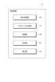
- FIG. 2 is a functional block diagram of the control device.
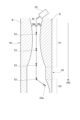
- FIG. 3A is a schematic diagram showing an opening when a partition wall having an internal space is formed by laminating weld beads.
- FIG. 3B is a schematic diagram showing an opening when a partition wall having an internal space is formed by laminating weld beads.
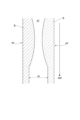
- FIG. 4 is a plan view of the opening shown in FIG. 3A.
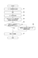
- FIG. 5 is a flowchart showing a procedure for closing an opening formed by stacking weld beads with a weld bead of a closing pass.
- FIG. 6 is an explanatory diagram schematically showing how the shape profile is measured.
- FIG. 1 is a schematic diagram showing the overall configuration of an additive manufacturing apparatus.
- FIG. 2 is a functional block diagram of the control device.
- FIG. 3A is a schematic diagram showing an opening when a partition wall having an internal space is formed by laminating weld beads
- FIG. 7 is an explanatory diagram showing a detection profile of detected reflected light.
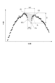
- FIG. 8 is a graph showing the shape profile measured by the profile measurement section by the shape detection section.
- FIG. 9 is an explanatory diagram showing an opening and a closing path for closing the opening.
- FIG. 10A is an explanatory diagram of the Uranami bead, and is a schematic cross-sectional view when the Uranami bead is not formed at the position of the closing path.
- FIG. 10B is an explanatory diagram of the Uranami bead, and is a schematic cross-sectional view when the Uranami bead is formed at the position of the closed path.
- FIG. 11 is a photograph of a cross section of a welded part when a notch-shaped welding failure occurs in the closing path.
- the additive manufacturing apparatus shown here is an example, and is equipped with a manipulator that holds a welding torch, and forms a model by laminating weld beads formed at the tip of the welding torch based on set lamination conditions. If so, other configurations may be used.
- FIG. 1 is a schematic diagram showing the overall configuration of an additive manufacturing apparatus.
- the layered manufacturing apparatus 100 includes a control device 11 and a modeling section 13.
- the modeling section 13 includes a manipulator 15, a filler material supply section 17, a manipulator control section 19, a heat source control section 21, and a shape detection section 23.
- the manipulator control section 19 controls the manipulator 15 and the heat source control section 21.
- a controller (not shown) is connected to the manipulator control section 19, and an operator can instruct any operation of the manipulator control section 19 via the controller.
- the manipulator 15 is, for example, a multi-joint robot, and is supported by a welding torch 25 provided on its tip shaft so that the filler material M can be continuously supplied. Welding torch 25 holds filler metal M in a state protruding from its tip. The position and orientation of the welding torch 25 can be arbitrarily set three-dimensionally within the degree of freedom of the robot arm that constitutes the manipulator 15.
- the manipulator 15 preferably has six or more degrees of freedom, and is preferably capable of arbitrarily changing the axial direction of the heat source at its tip.
- the manipulator 15 may take various forms, such as an articulated robot with four or more axes shown in FIG. 1 or a robot with angle adjustment mechanisms on two or more orthogonal axes.
- the welding torch 25 has a shield nozzle (not shown), and shield gas is supplied from the shield nozzle.
- the shielding gas blocks the atmosphere and prevents oxidation, nitridation, etc. of molten metal during welding, thereby suppressing welding defects.
- the arc welding method used in this configuration may be either a consumable electrode type such as coated arc welding or carbon dioxide arc welding, or a non-consumable electrode type such as TIG (Tungsten Inert Gas) welding or plasma arc welding. The selection will be made accordingly.
- gas metal arc welding will be explained as an example.
- a contact tip is arranged inside the shield nozzle, and the filler metal M to which a current is supplied is held in the contact tip.
- the welding torch 25 holds the filler metal M and generates an arc from the tip of the filler metal M in a shielding gas atmosphere.
- the filler metal supply section 17 supplies the filler metal M toward the welding torch 25.
- the filler material supply section 17 includes a reel 17a around which the filler material M is wound, and a feeding mechanism 17b that feeds out the filler material M from the reel 17a.
- the filler metal M is fed to the welding torch 25 by the feeding mechanism 17b while being fed in the forward or reverse direction as required.
- the feeding mechanism 17b is not limited to a push type that is placed on the side of the filler material supply section 17 and pushes out the filler material M, but may be a pull type or push-pull type that is placed on a robot arm or the like.
- the heat source control unit 21 is a welding power source that supplies the power required for welding by the manipulator 15.
- the heat source control unit 21 adjusts the welding current and welding voltage that are supplied when forming a bead in which the filler metal M is melted and solidified. Further, the filler metal supply speed of the filler metal supply unit 17 is adjusted in conjunction with welding conditions such as welding current and welding voltage set by the heat source control unit 21.
- the heat source for melting the filler metal M is not limited to the above-mentioned arc.
- heat sources using other methods may be used, such as a heating method using a combination of an arc and a laser, a heating method using plasma, a heating method using an electron beam or a laser.
- the amount of heating can be controlled more precisely, the state of the formed beads can be maintained more appropriately, and this can contribute to further improving the quality of the laminated structure.
- the material of the filler metal M is not particularly limited.
- the filler material used may be mild steel, high-strength steel, aluminum, aluminum alloy, nickel, nickel-based alloy, etc., depending on the characteristics of the shaped object Wk.
- the types of M may be different.
- the shape detection unit 23 is provided at or near the tip axis of the manipulator 15, and uses the vicinity of the tip of the welding torch 25 as a measurement area.
- the shape detection section 23 may be another detection means provided at a different position from the welding torch 25.
- the shape detection unit 23 of this configuration is moved together with the welding torch 25 by the drive of the manipulator 15, and measures the shape of the weld bead B and the portion that will become the base when the weld bead B is formed.
- a laser displacement sensor that acquires reflected light of the irradiated laser light as height information can be used.
- other detection means such as a camera for three-dimensional shape measurement may be used.
- the control device 11 centrally controls each of the above-mentioned parts.
- the control device 11 is configured by hardware using an information processing device such as a PC (Personal Computer), for example.
- Each function of the control device 11 is executed by a processor such as a CPU (Central Processing Unit) or an MPU (Micro Processor Unit), or a control device such as a dedicated circuit by executing a program having a specific function stored in a storage device (not shown). This is achieved by reading and executing it.
- Storage devices include RAM (Random Access Memory) which is a volatile storage area, ROM (Read Only Memory) which is a non-volatile storage area, HDD (Hard Disk Drive), SSD (Solid State Drive), etc. storage can be exemplified.
- the control device 11 may be another computer remotely connected to the additive manufacturing apparatus 100 via a network or the like.
- the layered manufacturing apparatus 100 configured as described above operates according to a modeling program created based on a modeling plan for the object Wk.
- the modeling program is composed of a large number of instruction codes, and is created based on an appropriate algorithm depending on various conditions such as the shape, material, and amount of heat input of the object Wk.
- a linear weld bead B which is a molten solidified body of the filler metal M, is formed on the base 27. be done. That is, the manipulator control section 19 drives the manipulator 15 and the heat source control section 21 based on a predetermined modeling program provided from the control device 11.
- the manipulator 15 moves the welding torch 25 to form the weld bead B while melting the filler metal M with an arc according to a command from the manipulator control unit 19 .
- a shaped article Wk having a desired shape can be obtained.
- the control device 11 also sends a drive signal to cause a machining device 33 having a cutting or polishing tool 31 such as an end mill or a drill on the tip shaft 29 to cut or polish the weld bead B at a predetermined timing. It may also have a function to output.
- a machining device 33 having a cutting or polishing tool 31 such as an end mill or a drill on the tip shaft 29 to cut or polish the weld bead B at a predetermined timing. It may also have a function to output.
- FIG. 2 is a functional block diagram of the control device 11.
- the control device 11 includes a condition acquisition section 35, a profile measurement section 37, a calculation section 39, a determination section 41, and a correction section 43. Details of the functions of the above-mentioned parts will be described later.
- FIG. 3A and 3B are schematic diagrams showing openings when forming a partition wall having an internal space by stacking weld beads.
- a pair of weld beads B are formed on the base 27 at positions separated from each other, and a new weld bead B is laminated on each weld bead B.
- a pair of laminates 45 consisting of a plurality of layers of weld beads B are formed by overhanging each other so as to approach each other, and an opening 47 formed between the weld beads Bt of the uppermost layer of each laminate 45 is formed by bead formation.
- the weld bead Bc is closed by the last pass (closing pass). In this way, an internal space 49 is formed inside the pair of laminates 45.
- the shape in which weld bead Bc and weld bead Bt are fused is referred to as a "closing portion.”
- the opening 47 described above is formed between the pair of laminates 45, and as shown in FIG. It may also be formed between the member 51 and the member 51.
- FIG. 4 is a plan view of the opening 47 shown in FIG. 3A.
- the shape of the weld bead B in the uppermost layer of the laminate 45 is not constant along the welding direction WD, and the actual opening 47 is formed with a different width W. Therefore, when the weld beads B are stacked to form a laminate having an internal space, the control device 11 of this configuration opens the openings 47 formed at the tops of a pair of laminates stacked from below. , closed by a weld bead in the closing pass. At this time, the control device 11 measures the shape of the opening 47 before forming the bead, and corrects the conditions for forming the weld bead that closes the opening 47 according to the shape of the opening 47.
- the lamination conditions of the weld bead Bc by the closing pass can be set in real time during modeling so that the opening 47 is reliably closed according to the shape of the opening 47.
- FIG. 5 is a flowchart showing a procedure for closing an opening formed by stacking weld beads with a weld bead of a closing pass. Each procedure is executed by each part of the control device 11 shown in FIG. 2 described above.
- the condition acquisition unit 35 acquires the lamination conditions and bead shape design values for the weld bead B to be laminated by the operation of the welding torch 25 shown in FIG. 1 (S1).
- the lamination conditions include information such as the formation trajectory (path) of the weld bead B and the welding conditions of the weld bead B when the object Wk is formed using the weld bead B. Further, the information on the lamination conditions may be extracted from the above-mentioned modeling program.
- the control device 11 drives the modeling unit 13 at a predetermined timing based on the acquired lamination conditions to form the weld bead B and start modeling (S2).
- FIG. 6 is an explanatory diagram schematically showing how the shape profile is measured.
- the shape detection unit 23 is disposed, for example, at the rear in the moving direction (welding direction WD) of the welding torch 25, and moves together with the movement of the welding torch 25.
- the shape detection unit 23 performs measurement based on a light cutting method in which the formed weld bead B is irradiated with slit light from an oblique direction and the reflected light of the irradiated slit light is detected.
- the shape detection method is not limited to this, and other methods may be used.
- FIG. 7 is an explanatory diagram showing the detection profile Prf of the detected reflected light.
- the upwardly convex region of the reflected light detection profile Prf indicates the position of the weld bead B.
- the detection profile Prf of the reflected light is a shape profile indicating height information of the measurement target.
- FIG. 8 is a graph showing a shape profile measured by the profile measurement section 37 and the shape detection section 23.
- This shape profile includes a pair of convex portions corresponding to a pair of weld beads B (laminated body 45) arranged opposite to each other, and a region corresponding to an opening 47 between the pair of convex portions. included. That is, as shown in FIG. 3A, the profile measurement unit 37 measures the shape of the upper layer portion (the uppermost layer weld bead Bt) where each of the pair of laminates 45 overhangs and protrudes the most.
- the apex of one convex portion (the convex portion on the left side) is the first maximum height point P1
- the apex of the other convex portion (the convex portion on the right side) is the first maximum height point P1.
- the point of the tip protruding downward along the opening from the first maximum height point P1 is defined as the first protruding tip point P3
- the point of the tip protruding downward along the opening from the second maximum height point P2 is defined as the first protruding tip point P3.
- the point is defined as a second protruding tip point P4.
- the calculation unit 39 specifies the amount of space indicating the size of the space of the opening or the representative position of the opening from the obtained shape profile (S4).
- Examples of the amount of space include, but are not limited to, the width, depth, and cross-sectional area of the opening in a cross section perpendicular to the bead forming direction (welding direction WD) of the weld bead.
- the width of the opening is the width W1 between the first maximum height point P1 and the second maximum height point P2 (the width between the two maximum height points), and the width W1 between the first maximum height point P1 and the second maximum height point P2, and the width between the first protrusion tip point P3 and the second maximum height point
- An example is the width W2 between the protrusion tip point P4 (width between two downwardly protruding points).
- the depth of the opening is determined by the higher of the first maximum height point P1 and the second maximum height point P2 (P1 in this case), the first protruding tip point P3, and the second protruding tip point P4.
- the depth D may be the height difference between the lower one (here, P4).
- This depth D represents the maximum depth at the opening of the measured shape profile.
- the depth D may be the difference between the average height of the first maximum height point P1 and the second maximum height point P2 and the average height of the first protrusion tip point P3 and the second protrusion tip point P4.
- the cross-sectional area A may be the area of a rectangle whose vertices are the points P1, P2, P3, and P4, or the area of the smallest circle that includes the points P1, P2, P3, and P4. It may be the area of any geometric figure whose vertices are points.
- the representative position is any position (coordinates) inside the geometric figure whose vertices are the above-mentioned points P1, P2, P3, and P4, and the position of the center point or center of gravity of the above-mentioned geometric figure. (coordinates) etc.
- the determination unit 41 compares the amount of space and the design value of the bead shape with respect to the closing path of closing the opening 47 with the weld bead formed based on the lamination conditions, and compares the information on the representative position and the information included in the lamination conditions.
- the success or failure of closing of the opening 47 is determined based on at least one of a comparison with the target position of the weld bead and whether or not a Uranami bead (details will be described later) is formed (S5).
- the size or bead shape of the weld bead is designed based on the lamination conditions for the widths W1, W2, depth D, cross-sectional area A, etc. of the area corresponding to the determined opening. If the difference between the calculated space amount and the design value is larger than a predetermined threshold value, it is determined that the stacking conditions of the closed path need to be corrected.
- the torch aim position (bead formation trajectory) included in the lamination conditions
- the amount of deviation (difference) between the determined representative position and the torch aim position is larger than a predetermined threshold value, it is determined that the lamination conditions of the closed path need to be corrected. Only one of these judgments may be made, or both may be made in combination. Especially when the two are combined, the weld bead lamination conditions of the closing pass can be precisely adjusted. Further, the success or failure of closing may be replaced with whether or not a Uranami bead is formed.
- the slope of the shape profile of the pair of convex parts (shape profile Prf shown in FIG. 7), the distance between the points where the pair of convex parts are closest (Wa shown in FIGS. 10A and 10B described later), or the convex shape profile Prf shown in FIG.
- the thickness of the shaped portion (for example, the depth D in FIG. 8) is compared with the design value, and if the amount of deviation between the two exceeds a predetermined value, it is determined that the formation of the Uranami bead is impossible. In this way, the success or failure of closing can be determined more accurately by determining whether or not the Uranami bead is formed. Further, the determination of success or failure of closing of the opening 47 may be performed by appropriately combining each of the above-mentioned comparisons and whether or not a Uranami bead can be formed.
- the control device 11 may control the machining device 33 shown in FIG. 1 at an appropriate timing to carry out repairs such as cutting and polishing of the narrow portion. According to this, it is possible to expand the range in which the shape of the opening can be handled.
- the correcting unit 43 corrects the lamination conditions of the closing path (S6).
- lamination conditions are set for the closing path according to the actual shape of the opening.
- a closed pass weld bead is formed based on the newly set lamination conditions (S7).
- a weld bead of a closing pass is formed while maintaining the set lamination conditions (S7).
- the lamination conditions of the closing path are corrected according to the shape of the opening. The specific contents of correcting the stacking conditions of the closed path will be described below.
- FIG. 9 is an explanatory diagram showing an opening and a closing path for closing the opening.
- the width of the opening 47 is not constant but varies along the welding direction WD.
- the width of the opening 47 is extremely narrow, such as region K1 in FIG. increase speed.
- the wire feeding speed is increased or the welding speed is decreased in order to increase the amount of welding.
- the mixing ratio of the shielding gas may be adjusted.
- Uranami beads can always be formed. More preferably, by adjusting the mixing ratio of Ar-CO 2 shielding gas in conjunction with changing the amount of welding, changing the amount of heat input, or changing the target position, the occurrence of shape defects and defect formation due to closing beads can be prevented. It can be suppressed.
- FIGS. 10A and 10B show explanatory diagrams of the Uranami bead.
- FIG. 10A is a schematic cross-sectional view when the Uranami bead is not formed at the position of the closing path
- FIG. 10B is a schematic cross-sectional view when the Uranami bead Bb is formed at the position of the closing path.
- the closing path is a path that fills the gap Wa between the tops of a pair of beads B stacked close to each other, and the weld bead Bc resulting from this closing path is shown as a hatched area. Point P in FIGS.
- the uranami bead Bb shown in FIG. 10B refers to a weld bead with a smooth surface that is formed on the opposite side (back side) of the welding torch in one-sided welding in which welding is performed from only one side, and is formed in one pass. Refers to welded metal.
- the strength decreases due to the thinning of the gap part, and the notch shape C is formed between the closing part and the bead adjacent to this closing part. It is easy to cause situations such as becoming a starting point for cracks.
- FIG. 11 is a photograph of a cross section of a welded part when a notch-shaped welding failure occurs in the closing path.
- the weaving width may be smaller in the region K1 than in other regions.
- the amount of heat input to the weld bead may be adjusted depending on the amount of space described above. For example, if the width of the opening 47 is too narrow for the assumed amount of space, reduce the welding current or welding voltage to reduce the amount of heat input, and conversely, if the width is too wide, reduce the welding current or welding voltage. increase.
- the target position of the welding torch 25 during the closing pass for closing the opening 47 may be corrected to the representative position described above.
- the target position may be corrected to be the center position or center of gravity of the opening 47.
- a target position 53 of the welding torch 25 shown in FIG. 9 is preferably set on a line where the distances Wa and Wb from the welding bead B on both sides of the opening 47 are equal.
- a target position 53a may be added at a position offset from the center in the width direction so that the welding torch 25 is shifted in the width direction in the area K2.
- the additional target position 53a is provided at a position that is biased toward one side (the right side in FIG. 9) of the pair of opposing weld beads B forming the opening 47 where the opening 47 is widened.
- the closing path is set to be bent toward the side where the width of the opening 47 is widened, and a weld bead is formed in the widened area. Therefore, the opening 47 can be closed while suppressing the occurrence of distortion, lack of thickness, and unwelded parts.
- the closing path is used to close the joined parts.
- Weld beads can be formed under appropriate lamination conditions that satisfy the space required for bead filling, such as the required width and thickness.
- the lamination conditions will be automatically set according to the shape change. , it is possible to improve the bonding quality of the opening. Therefore, there is no difference in quality between locations, and a molded object with good strength and quality control can be obtained.
- the amount of space or the representative position of the opening between weld beads is treated as a feature quantity for control, compared to the case where the shape of the weld bead itself to be formed is treated as a feature quantity, information such as the amount of welding that is required is required. becomes more accurate and the opening can be closed more reliably.
- a method for controlling an additive manufacturing apparatus that is equipped with a manipulator that moves a welding torch and that forms a model by laminating weld beads formed at the tip of the welding torch, the method comprising: obtaining lamination conditions and bead shape design values for the weld bead formed by moving the welding torch; Measure the shape of the opening defined between the weld beads formed based on the lamination conditions or between the weld bead and the surrounding member and the shape of the periphery of the opening, and determine the shape including the opening.
- the shape of the opening formed by modeling is measured to obtain a shape profile, and it is possible to determine the success or failure of closing by the closing pass for closing the opening from this shape profile. Therefore, when it is predicted that the opening cannot be closed, the opening can be reliably closed by correcting the stacking conditions of the closing path.
- the representative position is the first maximum height point of one of the pair of convex portions sandwiching the opening in the shape profile, and the distance from the first maximum height point to the opening. a first protruding tip point that protrudes downward, a second maximum height point of the other convex portion, and a second protruding tip point that protrudes downward from the second maximum height point of the opening.
- each representative position can be easily calculated using the shape profile, so that the layering conditions can be corrected more quickly. In other words, feedback control according to the amount of space can be quickly executed, and processing time can be shortened.
- Correction of the lamination conditions of the closing path includes adjusting the amount of welding or the amount of heat input of the weld bead that closes the opening according to the width of the opening determined from the shape profile.
- Correction of the lamination conditions of the closing path includes correcting the target position of the weld bead that closes the opening to the representative position, according to any one of (1) to (4).
- Correction of the lamination conditions of the closing path includes adding a target position of the closing path, Any one of (1) to (5), wherein the target position to be added is biased toward one of the pair of opposing weld beads forming the opening, which widens the opening.
- a control device for an additive manufacturing apparatus that is equipped with a manipulator that moves a welding torch and that forms a modeled object by laminating weld beads formed at the tip of the welding torch, a condition acquisition unit that acquires lamination conditions and bead shape design values for the weld bead formed by movement of the welding torch; Measure the shape of the opening defined between the weld beads formed based on the lamination conditions or between the weld bead and the surrounding member and the shape of the periphery of the opening, and determine the shape including the opening.
- a profile measurement unit that obtains a profile
- a specifying unit that specifies a space amount indicating the size of the space of the opening and a representative position of the opening based on the shape profile; Comparison of the amount of space and a design value of the bead shape, information on the representative position and the weld bead included in the lamination conditions regarding a closing path for closing the opening with a weld bead formed based on the lamination conditions.
- a determination unit that determines the success or failure of closing of the opening by at least one of a comparison with a target position and whether or not a Uranami bead is formed; a correction unit that corrects the lamination condition of the closing path when it is determined that the opening cannot be closed by the closing path;
- a control device for an additive manufacturing device According to the control device of this layered manufacturing apparatus, the shape of the opening formed by modeling can be measured to obtain a shape profile, and from this shape profile, it is possible to determine whether or not the opening is closed by a closing pass. Therefore, when it is predicted that the opening cannot be closed, the opening can be reliably closed by correcting the stacking conditions of the closing path.
- a program that executes a control procedure for an additive manufacturing apparatus that is equipped with a manipulator that moves a welding torch and that forms a model by laminating weld beads formed at the tip of the welding torch, the program comprising: to the computer, a step of acquiring lamination conditions and design values for the bead shape of the weld bead formed by moving the welding torch; Measure the shape of the opening defined between the weld beads formed based on the lamination conditions or between the weld bead and the surrounding member and the shape of the periphery of the opening, and determine the shape including the opening.
- the shape of the opening formed by modeling is measured to obtain a shape profile, and it is possible to determine the success or failure of closing the opening by the closing path based on this shape profile. Therefore, when it is predicted that the opening cannot be closed, the opening can be reliably closed by correcting the stacking conditions of the closing path.
- Control device 13 Modeling section 15 Manipulator 17 Filler material supply section 17a Reel 17b Feeding mechanism 19 Manipulator control section 21 Heat source control section 23 Shape detection section 25 Welding torch 27 Base 29 Tip shaft 31 Tool 33 Machining device 35 Condition acquisition section 37 Profile measurement unit 39 Calculation unit 41 Judgment unit 43 Correction unit 45 Laminated body 47 Opening 49 Internal space 51 Surrounding members 53, 53a Target position 100 Laminated manufacturing apparatus A Cross-sectional area B, Bc, Bt Weld bead D Depth K1, K2 Area M Filler metal P1 First maximum height point P2 Second maximum height point P3 First protruding tip point P4 Second protruding tip point Prf Detection profile W, W1, W2 Width WD Welding direction Wk Modeled object
Landscapes
- Engineering & Computer Science (AREA)
- Physics & Mathematics (AREA)
- Plasma & Fusion (AREA)
- Mechanical Engineering (AREA)
- Chemical & Material Sciences (AREA)
- Manufacturing & Machinery (AREA)
- Materials Engineering (AREA)
- Theoretical Computer Science (AREA)
- Butt Welding And Welding Of Specific Article (AREA)
- Arc Welding In General (AREA)
- General Factory Administration (AREA)
Abstract
Description
(1) 溶接トーチを移動させるマニピュレータを備え、前記溶接トーチの先端で形成される溶接ビードを積層して造形物を造形する積層造形装置の制御方法であって、
前記溶接トーチの移動により形成する前記溶接ビードの積層条件とビード形状の設計値を取得し、
前記積層条件に基づいて形成された前記溶接ビード同士の間、又は前記溶接ビードと周囲部材との間に画成される開口部及び開口部周囲の形状を計測して、前記開口部を含む形状プロファイルを求め、
前記形状プロファイルにより前記開口部の空間の大きさを示す空間量及び前記開口部の代表位置を特定し、
前記積層条件に基づき形成される溶接ビードにより前記開口部を閉合する閉合パスについて、前記空間量と前記ビード形状の設計値との比較、前記代表位置の情報と前記積層条件に含まれる前記溶接ビードの狙い位置との比較、及び裏波ビードの形成の可否の少なくともいずれかによって前記開口部の閉合の成否を判定し、
前記閉合パスによって前記開口部を閉合できないと判定した場合に前記閉合パスの前記積層条件を補正する、
積層造形装置の制御方法。
(2) 溶接トーチを移動させるマニピュレータを備え、前記溶接トーチの先端で形成される溶接ビードを積層して造形物を造形する積層造形装置の制御装置であって、
前記溶接トーチの移動により形成する前記溶接ビードの積層条件とビード形状の設計値を取得する条件取得部と、
前記積層条件に基づいて形成された前記溶接ビード同士の間、又は前記溶接ビードと周囲部材との間に画成される開口部及び開口部周囲の形状を計測して、前記開口部を含む形状プロファイルを求めるプロファイル計測部と、
前記形状プロファイルにより前記開口部の空間の大きさを示す空間量及び前記開口部の代表位置を特定する特定部と、
前記積層条件に基づき形成される溶接ビードにより前記開口部を閉合する閉合パスについて、前記空間量と前記ビード形状の設計値との比較、前記代表位置の情報と前記積層条件に含まれる前記溶接ビードの狙い位置との比較、及び裏波ビードの形成の可否の少なくともいずれかによって、前記開口部の閉合の成否を判定する判定部と、
前記閉合パスによって前記開口部を閉合できないと判定した場合に前記閉合パスの前記積層条件を補正する補正部と、
を備える積層造形装置の制御装置。
(3) 溶接トーチを移動させるマニピュレータを備え、前記溶接トーチの先端で形成される溶接ビードを積層して造形物を造形する積層造形装置の制御手順を実行するプログラムであって、
コンピュータに、
前記溶接トーチの移動により形成する前記溶接ビードの積層条件とビード形状の設計値を取得する手順と、
前記積層条件に基づいて形成された前記溶接ビード同士の間、又は前記溶接ビードと周囲部材との間に画成される開口部及び開口部周囲の形状を計測して、前記開口部を含む形状プロファイルを求める手順と、
前記形状プロファイルにより前記開口部の空間の大きさを示す空間量及び前記開口部の代表位置を特定する手順と、
前記積層条件に基づき形成される溶接ビードにより前記開口部を閉合する閉合パスについて、前記空間量と前記ビード形状の設計値との比較、前記代表位置の情報と前記積層条件に含まれる前記溶接ビードの狙い位置との比較、及び裏波ビードの形成の可否の少なくともいずれかによって、前記開口部の閉合の成否を判定する手順と、
前記閉合パスによって前記開口部を閉合できないと判定した場合に前記閉合パスの前記積層条件を補正する手順と、
を実行するためのプログラム。
図1は、積層造形装置の全体構成を示す概略図である。
積層造形装置100は、制御装置11と、造形部13とを備える。造形部13は、マニピュレータ15と、溶加材供給部17と、マニピュレータ制御部19と、熱源制御部21と、形状検出部23とを含んで構成される。
図3Aに示すように、一対の溶接ビードBをベース27上で互いに離れた位置に形成し、それぞれの溶接ビードBの上に新たに溶接ビードBを積層する。複数層の溶接ビードBからなる一対の積層体45を、互いに接近するようにオーバーハングさせて形成し、各積層体45の最上層の溶接ビードBt同士の間に生じる開口部47を、ビード形成の最後のパス(閉合パス)による溶接ビードBcで閉合する。こうして一対の積層体45の内側に内部空間49が形成される。本明細書では、溶接ビードBcと溶接ビードBtとが融合した形状を「閉合部」と呼称する。
図5は、溶接ビードの積層により形成される開口部を、閉合パスの溶接ビードで塞ぐ手順を示すフローチャートである。各手順は、前述した図2に示す制御装置11の各部によって実施される。
図6は、形状プロファイルの計測の様子を模式的に示す説明図である。形状検出部23は、例えば溶接トーチ25の移動方向(溶接方向WD)の例えば後方に配置され、溶接トーチ25の移動と一体となって移動する。形状検出部23は、形成された溶接ビードBに向けて斜め方向からスリット光を照射するとともに、照射されたスリット光の反射光を検出する、光切断法に基づいた計測を行う。形状検出の方式はこれに限らず、他の方式であってもよい。
この形状プロファイルには、互いに対向して配置された一対の溶接ビードB(積層体45)に対応する一対の凸状部と、一対の凸状部の間の開口部47に相当する領域とが含まれる。つまり、プロファイル計測部37は、図3Aに示すように、一対の積層体45がそれぞれオーバーハングして最も張り出した上層の部位(最上層の溶接ビードBt)の形状を計測する。
図9に示すように、開口部47の幅が溶接方向WDに沿って一定にならず変化する場合を考える。この場合、例えば、図9の領域K1のように開口部47の幅が極端に狭くなっている区間については、溶着量を抑えるために、他の区間よりもワイヤ送給速度を低下させたり溶接速度を上げたりする。逆に、幅が広くなった区間については、溶着量を増加させるために、ワイヤ送給速度を上げたり溶接速度を下げたりする。なお、溶着量変更に伴って開口部を閉合させた部分の裏側に裏波ビードが形成されないおそれがある場合は、シールドガスの混合比率を調整してもよい。例えばArとCO2の混合シールドガスにおいては、CO2の比率を増加させることで溶融金属の溶け込み量が増えるので、閉合パスの積層中にAr-CO2シールドガスの混合比率を調整することで裏波ビードを常に形成できる。さらに好ましくは、溶着量の変更、入熱量の変更、狙い位置の変更のいずれかと連動してAr-CO2シールドガスの混合比率を調整することで、閉合ビードによる形状不良や欠陥生成の発生を抑制できる。
(1) 溶接トーチを移動させるマニピュレータを備え、前記溶接トーチの先端で形成される溶接ビードを積層して造形物を造形する積層造形装置の制御方法であって、
前記溶接トーチの移動により形成する前記溶接ビードの積層条件とビード形状の設計値を取得し、
前記積層条件に基づいて形成された前記溶接ビード同士の間、又は前記溶接ビードと周囲部材との間に画成される開口部及び開口部周囲の形状を計測して、前記開口部を含む形状プロファイルを求め、
前記形状プロファイルにより前記開口部の空間の大きさを示す空間量及び前記開口部の代表位置を特定し、
前記積層条件に基づき形成される溶接ビードにより前記開口部を閉合する閉合パスについて、前記空間量と前記ビード形状の設計値との比較、前記代表位置の情報と前記積層条件に含まれる前記溶接ビードの狙い位置との比較、及び裏波ビードの形成の可否の少なくともいずれかによって前記開口部の閉合の成否を判定し、
前記閉合パスによって前記開口部を閉合できないと判定した場合に前記閉合パスの前記積層条件を補正する、
積層造形装置の制御方法。
この積層造形装置の制御方法によれば、造形により形成された開口部の形状を計測して形状プロファイルを求め、この形状プロファイルから開口部を閉合する閉合パスによる閉合の成否を判定できる。そのため、開口部を閉合できないと予測される場合に、閉合パスの積層条件を補正することで、開口部の閉合を確実に実施できる。
この積層造形装置の制御方法によれば、形状プロファイルを用いて、開口部に相当する領域の幅、深さ及び断面積のいずれかの空間量を簡単に算出できるため、積層条件の補正をより早く実施できる。つまり、空間量に応じたフィードバック制御を素早く実行でき、処理時間の短縮化が図れる。
この積層造形装置の制御方法によれば、形状プロファイルを用いて各代表位置を簡単に算出できるため、積層条件の補正をより早く実施できる。つまり、空間量に応じたフィードバック制御を素早く実行でき、処理時間の短縮化が図れる。
この積層造形装置の制御方法によれば、開口部の幅が想定した幅と異なる場合に、溶着量をワイヤ送給速度、溶接速度を増減させて溶着量を調整したり、溶接電流、溶接電圧を増減させて入熱量を調整したりして、適切な条件で閉合パスの溶接ビードを形成できる。これにより、過剰又は過少なビードの溶着と、ビードの溶け落ちを防止できる。
この積層造形装置の制御方法によれば、閉合パスの溶接ビードの狙い位置を代表位置に修正することで、溶接トーチの位置が適正に保たれ、トーチの空振り、他部材との干渉を抑制できる。
追加する前記狙い位置を、前記開口部を形成する一対の対向する溶接ビードのうち前記開口部を拡幅させるいずれか一方の側に偏らせて設ける、(1)から(5)のいずれか1つに記載の積層造形装置の制御方法。
この積層造形装置の制御方法によれば、狙い位置の追加によって、閉合パスが、開口部の幅を広げる側に折れ曲がって設定され、幅が広がった部位に溶接ビードが盛られる。そのため、歪み、欠肉、未溶着部位の発生を抑制しつつ開口部を閉合できる。
この積層造形装置の制御方法によれば、閉合パスの積層中に混合シールドガスの混合比率を調整することで裏波ビードを常に形成でき、閉合部の薄肉による強度の低下、閉合部が亀裂発生の起点となる等の形状不良、欠陥発生の発生を抑制できる。
前記溶接トーチの移動により形成する前記溶接ビードの積層条件とビード形状の設計値を取得する条件取得部と、
前記積層条件に基づいて形成された前記溶接ビード同士の間、又は前記溶接ビードと周囲部材との間に画成される開口部及び開口部周囲の形状を計測して、前記開口部を含む形状プロファイルを求めるプロファイル計測部と、
前記形状プロファイルにより前記開口部の空間の大きさを示す空間量及び前記開口部の代表位置を特定する特定部と、
前記積層条件に基づき形成される溶接ビードにより前記開口部を閉合する閉合パスについて、前記空間量と前記ビード形状の設計値との比較、前記代表位置の情報と前記積層条件に含まれる前記溶接ビードの狙い位置との比較、及び裏波ビードの形成の可否の少なくともいずれかによって、前記開口部の閉合の成否を判定する判定部と、
前記閉合パスによって前記開口部を閉合できないと判定した場合に前記閉合パスの前記積層条件を補正する補正部と、
を備える積層造形装置の制御装置。
この積層造形装置の制御装置によれば、造形により形成された開口部の形状を計測して形状プロファイルを求め、この形状プロファイルから開口部を閉合する閉合パスによる閉合の成否を判定できる。そのため、開口部を閉合できないと予測される場合に、閉合パスの積層条件を補正することで、開口部の閉合を確実に実施できる。
コンピュータに、
前記溶接トーチの移動により形成する前記溶接ビードの積層条件とビード形状の設計値を取得する手順と、
前記積層条件に基づいて形成された前記溶接ビード同士の間、又は前記溶接ビードと周囲部材との間に画成される開口部及び開口部周囲の形状を計測して、前記開口部を含む形状プロファイルを求める手順と、
前記形状プロファイルにより前記開口部の空間の大きさを示す空間量及び前記開口部の代表位置を特定する手順と、
前記積層条件に基づき形成される溶接ビードにより前記開口部を閉合する閉合パスについて、前記空間量と前記ビード形状の設計値との比較、前記代表位置の情報と前記積層条件に含まれる前記溶接ビードの狙い位置との比較、及び裏波ビードの形成の可否の少なくともいずれかによって、前記開口部の閉合の成否を判定する手順と、
前記閉合パスによって前記開口部を閉合できないと判定した場合に前記閉合パスの前記積層条件を補正する手順と、
を実行するためのプログラム。
このプログラムによれば、造形により形成された開口部の形状を計測して形状プロファイルを求め、この形状プロファイルから開口部を閉合する閉合パスによる閉合の成否を判定できる。そのため、開口部を閉合できないと予測される場合に、閉合パスの積層条件を補正することで、開口部の閉合を確実に実施できる。
13 造形部
15 マニピュレータ
17 溶加材供給部
17a リール
17b 繰り出し機構
19 マニピュレータ制御部
21 熱源制御部
23 形状検出部
25 溶接トーチ
27 ベース
29 先端軸
31 工具
33 機械加工装置
35 条件取得部
37 プロファイル計測部
39 演算部
41 判定部
43 補正部
45 積層体
47 開口部
49 内部空間
51 周囲部材
53,53a 狙い位置
100 積層造形装置
A 断面積
B,Bc,Bt 溶接ビード
D 深さ
K1,K2 領域
M 溶加材
P1 第一最大高さ点
P2 第二最大高さ点
P3 第一突出先端点
P4 第二突出先端点
Prf 検出プロファイル
W,W1,W2 幅
WD 溶接方向
Wk 造形物
Claims (9)
- 溶接トーチを移動させるマニピュレータを備え、前記溶接トーチの先端で形成される溶接ビードを積層して造形物を造形する積層造形装置の制御方法であって、
前記溶接トーチの移動により形成する前記溶接ビードの積層条件とビード形状の設計値を取得し、
前記積層条件に基づいて形成された前記溶接ビード同士の間、又は前記溶接ビードと周囲部材との間に画成される開口部及び開口部周囲の形状を計測して、前記開口部を含む形状プロファイルを求め、
前記形状プロファイルにより前記開口部の空間の大きさを示す空間量及び前記開口部の代表位置を特定し、
前記積層条件に基づき形成される溶接ビードにより前記開口部を閉合する閉合パスについて、前記空間量と前記ビード形状の設計値との比較、前記代表位置の情報と前記積層条件に含まれる前記溶接ビードの狙い位置との比較、及び裏波ビードの形成の可否の少なくともいずれかによって前記開口部の閉合の成否を判定し、
前記閉合パスによって前記開口部を閉合できないと判定した場合に前記閉合パスの前記積層条件を補正する、
積層造形装置の制御方法。 - 前記空間量は、前記形状プロファイルにおける前記開口部に相当する領域の幅、深さ及び断面積のいずれかを含む、
請求項1に記載の積層造形装置の制御方法。 - 前記代表位置は、前記形状プロファイルにおける前記開口部を挟んだ一対の凸状部のうち、一方の凸状部の第一最大高さ点、当該第一最大高さ点から前記開口部の下方へ突出した第一突出先端点、及び、他方の凸状部の第二最大高さ点、当該第二最大高さ点から前記開口部の下方へ突出した第二突出先端点の各点を頂点とする幾何図形の内側の点のいずれかである、
請求項1に記載の積層造形装置の制御方法。 - 前記閉合パスの前記積層条件の補正は、前記形状プロファイルから求める前記開口部の幅に応じて、前記開口部を閉合する前記溶接ビードの溶着量又は入熱量を調整することを含む、
請求項1に記載の積層造形装置の制御方法。 - 前記閉合パスの前記積層条件の補正は、前記開口部を閉合する前記溶接ビードの狙い位置を前記代表位置に修正することを含む、
請求項1に記載の積層造形装置の制御方法。 - 前記閉合パスの前記積層条件の補正は、前記閉合パスの狙い位置の追加を含み、
追加する前記狙い位置を、前記開口部を形成する一対の対向する溶接ビードのうち前記開口部を拡幅させるいずれか一方の側に偏らせて設ける、
請求項1に記載の積層造形装置の制御方法。 - 前記閉合パスの前記積層条件の補正は、前記溶接ビードの積層に使用する混合シールドガスの混合比率を調整することを含む、
請求項1に記載の積層造形装置の制御方法。 - 溶接トーチを移動させるマニピュレータを備え、前記溶接トーチの先端で形成される溶接ビードを積層して造形物を造形する積層造形装置の制御装置であって、
前記溶接トーチの移動により形成する前記溶接ビードの積層条件とビード形状の設計値を取得する条件取得部と、
前記積層条件に基づいて形成された前記溶接ビード同士の間、又は前記溶接ビードと周囲部材との間に画成される開口部及び開口部周囲の形状を計測して、前記開口部を含む形状プロファイルを求めるプロファイル計測部と、
前記形状プロファイルにより前記開口部の空間の大きさを示す空間量及び前記開口部の代表位置を特定する特定部と、
前記積層条件に基づき形成される溶接ビードにより前記開口部を閉合する閉合パスについて、前記空間量と前記ビード形状の設計値との比較、前記代表位置の情報と前記積層条件に含まれる前記溶接ビードの狙い位置との比較、及び裏波ビードの形成の可否の少なくともいずれかによって、前記開口部の閉合の成否を判定する判定部と、
前記閉合パスによって前記開口部を閉合できないと判定した場合に前記閉合パスの前記積層条件を補正する補正部と、
を備える積層造形装置の制御装置。 - 溶接トーチを移動させるマニピュレータを備え、前記溶接トーチの先端で形成される溶接ビードを積層して造形物を造形する積層造形装置の制御手順を実行するプログラムであって、
コンピュータに、
前記溶接トーチの移動により形成する前記溶接ビードの積層条件とビード形状の設計値を取得する手順と、
前記積層条件に基づいて形成された前記溶接ビード同士の間、又は前記溶接ビードと周囲部材との間に画成される開口部及び開口部周囲の形状を計測して、前記開口部を含む形状プロファイルを求める手順と、
前記形状プロファイルにより前記開口部の空間の大きさを示す空間量及び前記開口部の代表位置を特定する手順と、
前記積層条件に基づき形成される溶接ビードにより前記開口部を閉合する閉合パスについて、前記空間量と前記ビード形状の設計値との比較、前記代表位置の情報と前記積層条件に含まれる前記溶接ビードの狙い位置との比較、及び裏波ビードの形成の可否の少なくともいずれかによって、前記開口部の閉合の成否を判定する手順と、
前記閉合パスによって前記開口部を閉合できないと判定した場合に前記閉合パスの前記積層条件を補正する手順と、
を実行するためのプログラム。
Priority Applications (3)
| Application Number | Priority Date | Filing Date | Title |
|---|---|---|---|
| EP23831214.4A EP4527534A4 (en) | 2022-06-30 | 2023-06-20 | METHOD, DEVICE AND CONTROL PROGRAM FOR AN ADDITIVE MANUFACTURING DEVICE |
| CN202380050591.0A CN119451766A (zh) | 2022-06-30 | 2023-06-20 | 层叠造型装置的控制方法及控制装置以及程序 |
| US18/877,800 US20250381609A1 (en) | 2022-06-30 | 2023-06-20 | Control method and control device for additive manufacturing device, and program |
Applications Claiming Priority (2)
| Application Number | Priority Date | Filing Date | Title |
|---|---|---|---|
| JP2022106144A JP7697912B2 (ja) | 2022-06-30 | 2022-06-30 | 積層造形装置の制御方法及び制御装置並びにプログラム |
| JP2022-106144 | 2022-06-30 |
Publications (1)
| Publication Number | Publication Date |
|---|---|
| WO2024004768A1 true WO2024004768A1 (ja) | 2024-01-04 |
Family
ID=89382232
Family Applications (1)
| Application Number | Title | Priority Date | Filing Date |
|---|---|---|---|
| PCT/JP2023/022824 Ceased WO2024004768A1 (ja) | 2022-06-30 | 2023-06-20 | 積層造形装置の制御方法及び制御装置並びにプログラム |
Country Status (5)
| Country | Link |
|---|---|
| US (1) | US20250381609A1 (ja) |
| EP (1) | EP4527534A4 (ja) |
| JP (1) | JP7697912B2 (ja) |
| CN (1) | CN119451766A (ja) |
| WO (1) | WO2024004768A1 (ja) |
Families Citing this family (2)
| Publication number | Priority date | Publication date | Assignee | Title |
|---|---|---|---|---|
| JP7570565B1 (ja) * | 2024-01-26 | 2024-10-21 | 三菱電機株式会社 | 付加製造方法および付加製造装置 |
| JP2025125886A (ja) * | 2024-02-16 | 2025-08-28 | 三菱重工業株式会社 | 溶接条件設定装置、溶接条件設定方法及びプログラム |
Citations (7)
| Publication number | Priority date | Publication date | Assignee | Title |
|---|---|---|---|---|
| JP2021007960A (ja) * | 2019-06-28 | 2021-01-28 | 株式会社神戸製鋼所 | 積層造形物の製造方法 |
| JP6896193B1 (ja) | 2020-08-26 | 2021-06-30 | 三菱電機株式会社 | 積層造形装置 |
| JP2022034759A (ja) * | 2020-08-19 | 2022-03-04 | 株式会社神戸製鋼所 | 積層造形物の製造システム、積層造形物の製造方法、及び積層造形物の製造プログラム |
| JP2022039535A (ja) * | 2020-08-28 | 2022-03-10 | 株式会社神戸製鋼所 | 造形物の製造方法及び造形物 |
| JP2022095534A (ja) * | 2020-12-16 | 2022-06-28 | 株式会社神戸製鋼所 | 造形物の製造方法及び造形物 |
| JP2022106144A (ja) | 2021-01-06 | 2022-07-19 | 凸版印刷株式会社 | めっき治具 |
| WO2023281963A1 (ja) * | 2021-07-09 | 2023-01-12 | 株式会社神戸製鋼所 | 欠陥監視装置、欠陥監視方法、溶接支援システム及び溶接システム |
Family Cites Families (3)
| Publication number | Priority date | Publication date | Assignee | Title |
|---|---|---|---|---|
| US20190377326A1 (en) * | 2018-03-02 | 2019-12-12 | Mitsubishi Electric Corporation | Additive manufacturing apparatus and additive manufacturing method |
| JP7123738B2 (ja) * | 2018-10-24 | 2022-08-23 | 株式会社神戸製鋼所 | 積層造形物の製造方法及び積層造形物 |
| JP7303162B2 (ja) * | 2020-07-15 | 2023-07-04 | 株式会社神戸製鋼所 | 積層造形物の製造方法 |
-
2022
- 2022-06-30 JP JP2022106144A patent/JP7697912B2/ja active Active
-
2023
- 2023-06-20 US US18/877,800 patent/US20250381609A1/en active Pending
- 2023-06-20 WO PCT/JP2023/022824 patent/WO2024004768A1/ja not_active Ceased
- 2023-06-20 EP EP23831214.4A patent/EP4527534A4/en active Pending
- 2023-06-20 CN CN202380050591.0A patent/CN119451766A/zh active Pending
Patent Citations (7)
| Publication number | Priority date | Publication date | Assignee | Title |
|---|---|---|---|---|
| JP2021007960A (ja) * | 2019-06-28 | 2021-01-28 | 株式会社神戸製鋼所 | 積層造形物の製造方法 |
| JP2022034759A (ja) * | 2020-08-19 | 2022-03-04 | 株式会社神戸製鋼所 | 積層造形物の製造システム、積層造形物の製造方法、及び積層造形物の製造プログラム |
| JP6896193B1 (ja) | 2020-08-26 | 2021-06-30 | 三菱電機株式会社 | 積層造形装置 |
| JP2022039535A (ja) * | 2020-08-28 | 2022-03-10 | 株式会社神戸製鋼所 | 造形物の製造方法及び造形物 |
| JP2022095534A (ja) * | 2020-12-16 | 2022-06-28 | 株式会社神戸製鋼所 | 造形物の製造方法及び造形物 |
| JP2022106144A (ja) | 2021-01-06 | 2022-07-19 | 凸版印刷株式会社 | めっき治具 |
| WO2023281963A1 (ja) * | 2021-07-09 | 2023-01-12 | 株式会社神戸製鋼所 | 欠陥監視装置、欠陥監視方法、溶接支援システム及び溶接システム |
Non-Patent Citations (1)
| Title |
|---|
| See also references of EP4527534A4 |
Also Published As
| Publication number | Publication date |
|---|---|
| CN119451766A (zh) | 2025-02-14 |
| EP4527534A1 (en) | 2025-03-26 |
| EP4527534A4 (en) | 2026-01-14 |
| US20250381609A1 (en) | 2025-12-18 |
| JP7697912B2 (ja) | 2025-06-24 |
| JP2024005776A (ja) | 2024-01-17 |
Similar Documents
| Publication | Publication Date | Title |
|---|---|---|
| JP6912636B1 (ja) | 積層造形物の製造システム、積層造形物の製造方法、及び積層造形物の製造プログラム | |
| WO2021235369A1 (ja) | 積層造形方法 | |
| WO2024004768A1 (ja) | 積層造形装置の制御方法及び制御装置並びにプログラム | |
| JP7586715B2 (ja) | 積層造形物の製造方法 | |
| US12547140B2 (en) | Stacking plan creating method | |
| JP2019098381A (ja) | 積層造形物の製造方法及び製造装置 | |
| JP2020066027A (ja) | 積層造形物の製造方法及び積層造形物 | |
| JP7409997B2 (ja) | 積層造形物の製造方法 | |
| JP7339215B2 (ja) | 積層造形物の製造システム、積層造形物の製造方法、及び積層造形物の製造プログラム | |
| CN119630502A (zh) | 控制信息修正方法、控制信息修正装置以及程序 | |
| JP7684253B2 (ja) | 軌道計画支援装置、軌道計画支援方法及びプログラム | |
| JP2022039535A (ja) | 造形物の製造方法及び造形物 | |
| JP2021126673A (ja) | 積層造形物の製造方法 | |
| JP7794721B2 (ja) | 造形物の製造方法及び積層計画方法 | |
| WO2022163328A1 (ja) | 造形履歴監視装置、造形物の製造システム及び造形履歴監視方法 | |
| JP7522078B2 (ja) | 溶接装置、積層造形装置及び位置決め方法 | |
| JP7556837B2 (ja) | 造形物の製造方法及び連結器の製造方法 | |
| JP7768862B2 (ja) | 狙い位置設定方法、狙い位置設定装置及びプログラム | |
| JP7688010B2 (ja) | 造形物の製造方法及び製造装置 | |
| JP6783964B1 (ja) | 積層造形物の製造方法 | |
| JP2024161745A (ja) | 積層計画情報生成装置及び積層計画情報生成方法、並びにプログラム | |
| JP2024025180A (ja) | 制御情報生成装置、制御情報生成方法、プログラム及び積層造形方法 |
Legal Events
| Date | Code | Title | Description |
|---|---|---|---|
| 121 | Ep: the epo has been informed by wipo that ep was designated in this application |
Ref document number: 23831214 Country of ref document: EP Kind code of ref document: A1 |
|
| WWE | Wipo information: entry into national phase |
Ref document number: 2023831214 Country of ref document: EP |
|
| WWE | Wipo information: entry into national phase |
Ref document number: 18877800 Country of ref document: US |
|
| WWE | Wipo information: entry into national phase |
Ref document number: 202380050591.0 Country of ref document: CN |
|
| ENP | Entry into the national phase |
Ref document number: 2023831214 Country of ref document: EP Effective date: 20241219 |
|
| NENP | Non-entry into the national phase |
Ref country code: DE |
|
| WWP | Wipo information: published in national office |
Ref document number: 202380050591.0 Country of ref document: CN |
|
| WWP | Wipo information: published in national office |
Ref document number: 18877800 Country of ref document: US |