WO2024010086A1 - Matériau de rembourrage, siège et siège de véhicule - Google Patents
Matériau de rembourrage, siège et siège de véhicule Download PDFInfo
- Publication number
- WO2024010086A1 WO2024010086A1 PCT/JP2023/025280 JP2023025280W WO2024010086A1 WO 2024010086 A1 WO2024010086 A1 WO 2024010086A1 JP 2023025280 W JP2023025280 W JP 2023025280W WO 2024010086 A1 WO2024010086 A1 WO 2024010086A1
- Authority
- WO
- WIPO (PCT)
- Prior art keywords
- seat
- pad material
- urethane
- seated person
- biomass
- Prior art date
- Legal status (The legal status is an assumption and is not a legal conclusion. Google has not performed a legal analysis and makes no representation as to the accuracy of the status listed.)
- Ceased
Links
Images




Classifications
-
- B—PERFORMING OPERATIONS; TRANSPORTING
- B60—VEHICLES IN GENERAL
- B60N—SEATS SPECIALLY ADAPTED FOR VEHICLES; VEHICLE PASSENGER ACCOMMODATION NOT OTHERWISE PROVIDED FOR
- B60N2/00—Seats specially adapted for vehicles; Arrangement or mounting of seats in vehicles
- B60N2/56—Heating or ventilating devices
- B60N2/5607—Heating or ventilating devices characterised by convection
- B60N2/5621—Heating or ventilating devices characterised by convection by air
- B60N2/5642—Heating or ventilating devices characterised by convection by air with circulation of air through a layer inside the seat
-
- A—HUMAN NECESSITIES
- A47—FURNITURE; DOMESTIC ARTICLES OR APPLIANCES; COFFEE MILLS; SPICE MILLS; SUCTION CLEANERS IN GENERAL
- A47C—CHAIRS; SOFAS; BEDS
- A47C7/00—Parts, details, or accessories of chairs or stools
- A47C7/62—Accessories for chairs
- A47C7/72—Adaptations for incorporating lamps, radio sets, bars, telephones, ventilation, heating or cooling arrangements or the like
- A47C7/74—Adaptations for incorporating lamps, radio sets, bars, telephones, ventilation, heating or cooling arrangements or the like for ventilation, heating or cooling
-
- B—PERFORMING OPERATIONS; TRANSPORTING
- B60—VEHICLES IN GENERAL
- B60N—SEATS SPECIALLY ADAPTED FOR VEHICLES; VEHICLE PASSENGER ACCOMMODATION NOT OTHERWISE PROVIDED FOR
- B60N2/00—Seats specially adapted for vehicles; Arrangement or mounting of seats in vehicles
- B60N2/56—Heating or ventilating devices
-
- B—PERFORMING OPERATIONS; TRANSPORTING
- B60—VEHICLES IN GENERAL
- B60N—SEATS SPECIALLY ADAPTED FOR VEHICLES; VEHICLE PASSENGER ACCOMMODATION NOT OTHERWISE PROVIDED FOR
- B60N2/00—Seats specially adapted for vehicles; Arrangement or mounting of seats in vehicles
- B60N2/56—Heating or ventilating devices
- B60N2/5607—Heating or ventilating devices characterised by convection
- B60N2/5621—Heating or ventilating devices characterised by convection by air
- B60N2/5657—Heating or ventilating devices characterised by convection by air blown towards the seat surface
-
- B—PERFORMING OPERATIONS; TRANSPORTING
- B60—VEHICLES IN GENERAL
- B60N—SEATS SPECIALLY ADAPTED FOR VEHICLES; VEHICLE PASSENGER ACCOMMODATION NOT OTHERWISE PROVIDED FOR
- B60N2/00—Seats specially adapted for vehicles; Arrangement or mounting of seats in vehicles
- B60N2/56—Heating or ventilating devices
- B60N2/5678—Heating or ventilating devices characterised by electrical systems
- B60N2/5685—Resistance
-
- B—PERFORMING OPERATIONS; TRANSPORTING
- B60—VEHICLES IN GENERAL
- B60N—SEATS SPECIALLY ADAPTED FOR VEHICLES; VEHICLE PASSENGER ACCOMMODATION NOT OTHERWISE PROVIDED FOR
- B60N2/00—Seats specially adapted for vehicles; Arrangement or mounting of seats in vehicles
- B60N2/70—Upholstery springs ; Upholstery
-
- B—PERFORMING OPERATIONS; TRANSPORTING
- B60—VEHICLES IN GENERAL
- B60N—SEATS SPECIALLY ADAPTED FOR VEHICLES; VEHICLE PASSENGER ACCOMMODATION NOT OTHERWISE PROVIDED FOR
- B60N2/00—Seats specially adapted for vehicles; Arrangement or mounting of seats in vehicles
- B60N2/90—Details or parts not otherwise provided for
-
- B—PERFORMING OPERATIONS; TRANSPORTING
- B60—VEHICLES IN GENERAL
- B60N—SEATS SPECIALLY ADAPTED FOR VEHICLES; VEHICLE PASSENGER ACCOMMODATION NOT OTHERWISE PROVIDED FOR
- B60N2/00—Seats specially adapted for vehicles; Arrangement or mounting of seats in vehicles
- B60N2/80—Head-rests
- B60N2002/899—Head-rests characterised by structural or mechanical details not otherwise provided for
Definitions
- Biomass urethane is a urethane foam containing raw materials containing biomass resources such as renewable plants. Cushion members made of biomass urethane can be applied to various locations such as vehicle seats, cushions, sofas, and door linings.
- the pad material includes a first cushion member made of biomass urethane and a second cushion member made of urethane foam. Since the pad material is composed of cushion members having different hardnesses, deformation of the first cushion member made of biomass urethane can be suppressed by the second cushion member, which is less deformable than the first cushion member.
- the pad material as disclosed in Patent Document 1 is composed of cushion members having different hardnesses, there is a possibility that the seated person may feel uncomfortable at the boundary between the cushion members.
- the entire or part of the pad material is made of biomass urethane, which is harder than urethane foam, it is possible to be environmentally friendly, but there is a need for further improvement in sitting comfort.
- the present invention has been made in view of the above-mentioned problems, and an object of the present invention is to provide a pad material, a seating seat, and a vehicle for use in vehicles, which improve sitting comfort while being environmentally friendly and do not cause discomfort to the occupant.
- the purpose is to provide seats.
- an environmentally friendly padding material can be achieved, and by using urethane foam, which is softer than biomass urethane, for the seating surface, it is possible to improve sitting comfort. . Additionally, since the entire overhang is made of high-hardness biomass urethane, the boundary of the cushion member is not exposed at the overhang, making it possible to improve sitting comfort without making the occupant feel uncomfortable. .
- the entirety of the overhang portion and the side portion of the pad material be formed of biomass urethane.
- the entire projecting portion and side portion are made of high hardness biomass urethane. Therefore, it is possible to increase the rigidity of the overhang portion and the side portions, improve sitting comfort, and enhance the feeling of holding the pad material.
- the side part is arranged adjacent to the base part, and the boundary part between the base part and the side part extends from the seating surface of the pad material toward the back surface opposite to the seating surface.
- the pad material may extend perpendicularly to the seating surface of the pad material.
- the pad material is used as a seat cushion of the sitting seat, the base part supports the seated person from below, the projecting part has a substantially U-shape when viewed from above, and the It is preferable that it be formed so as to surround the base part.
- the seat is provided with a pad material and a headrest pad material that supports the head of the seated person, and at least a portion of the headrest pad material that corresponds to the head of the seated person is , it is preferably made of a material different from biomass urethane.
- biomass urethane has high hardness, it is brittle and susceptible to impact. Therefore, if biomass urethane is used for the headrest, there is a risk that the headrest will be damaged by impact. Therefore, by forming the headrest pad material from a material other than biomass urethane, damage to the headrest can be suppressed.
- the sitting seat is provided with an air blower provided in the pad material, an air passage through which air from the air blower passes is formed inside the pad material, and the heat insulating material is provided with the air blower. It is preferable that a through hole is formed to allow wind from the road to pass through.
- a passage hole through which air from the ventilation path passes is formed in the heater base material at a position facing the through hole of the heat insulating material.
- a vehicle seat comprising a pad material for supporting a seated person and a seat frame on which the pad material is disposed
- the vehicle seat including the pad material includes a base portion that supports the seated person, a side portion disposed on the outside of the base portion in the seat width direction, and a tension member that extends from the side portion toward the seated person and supports the seated person from the side.
- a protruding part, of the pad material, the entire protruding part is made of biomass urethane, and at least a part of the base part is made of a material softer than the biomass urethane. resolved.
- the present invention it is possible to suppress deterioration of biomass urethane due to the influence of heat from the heater wire. Further, according to the present invention, it is possible to improve the warm sensation and cool sensation of the seated person. Further, according to the present invention, it is possible to further improve the warm sensation and cool sensation of the seated person.
- FIG. 1 is a perspective view of a vehicle seat according to the present embodiment. It is a top view of a pad material.
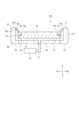
- 3 is a sectional view taken along line III-III in FIG. 2.
- FIG. FIG. 3 is a cross-sectional view of a pad material of Modification 1.
- FIG. 7 is a cross-sectional view of a pad material of Modification 2.
- FIG. 7 is a cross-sectional view of a pad material of Modification 3.
- FIG. 7 is a cross-sectional view of a pad material of Modification 4.
- FIG. 7 is a cross-sectional view of a pad material according to modification 5.
- FIG. 7 is a top view of a pad material of Modification 6.
- FIG. 9 is a sectional view taken along line XX in FIG. 9; FIG.
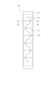
- FIG. 3 is a top view of the seat heater. 12 is a sectional view taken along line XII-XII in FIG. 11.
- FIG. 7 is a perspective view of a vehicle seat according to Modification Example 7;
- FIG. 7 is a perspective view of a vehicle seat according to Modification 8.
- FIG. 7 is a perspective view of a vehicle seat according to modification 9.
- FIG. 7 is a perspective view of a vehicle seat according to Modification 10.
- FIG. 7 is a perspective view of a vehicle seat according to Modification 11;
- the sitting seat of this embodiment is, for example, a vehicle seat S installed in a vehicle.
- vehicle seat S may be, for example, a seat installed in a ship, an aircraft, or the like.
- the sitting seat is not limited to the vehicle seat S, but may be a seat such as a general chair, sofa, or cushion.
- the "front-rear direction” refers to the front-rear direction of the vehicle seat S, and is a direction that coincides with the direction in which the vehicle travels.
- the "seat width direction” is the width direction of the vehicle seat S, and is a direction that coincides with the left-right direction as seen from a person seated on the vehicle seat S.
- the “vertical direction” refers to the vertical direction of the vehicle seat S, and is a direction that coincides with the vertical direction when the vehicle is traveling on a horizontal plane.
- the vehicle seat S mainly includes a seat back 1, a seat cushion 2 connected to the lower part of the seat back 1, and a headrest 3 connected to the upper part of the seat back 1. It is configured.
- the seat back 1 is a backrest portion that supports the back of a seated person from behind, and is constructed by placing a pad material 1a on a seat frame 4 (back frame 4a) serving as a skeleton and covering it with a skin material 1b. has been done.
- the seat cushion 2 is a seating part that supports a seated person from below, and a padding material 2a is placed on a seat frame 4 (cushion frame 4b) serving as a skeleton, and a skin material 2b is placed over the padding material 2a. It is covered and constructed.
- the headrest 3 is a head that supports the head of a seated person from behind, and is constructed by placing a padding material 3a on a not-shown headrest pillar serving as a core material, and covering the padding material 3a with a skin material 3b.
- FIG. 2 shows a cushion main body portion 10 that is a pad material 2a that constitutes the seat cushion 2.
- the structure of the padding material 1a constituting the seat back 1 is substantially the same as that of the padding material 2a constituting the seat cushion 2, so a description thereof will be omitted.
- the cushion main body 10 is a pad material 2a for supporting a seated person, and includes a first cushion member 20 serving as a seating portion, a second cushion member 30 provided around the first cushion member 20, and a cushion main body. 10 and an engaging portion 50 provided in the groove 40.
- the cushion main body portion 10 is covered with the skin material 2b by suspending the skin material 2b by the engaging portion 50 provided in the groove portion 40.
- the first cushion member 20, the second cushion member 30, and the engaging portion 50 are integrally formed, for example, by insert molding.
- the first cushion member 20 has a base portion 21 provided at the center of the cushion body portion 10, as shown in FIGS. 2 and 3. As shown in FIGS.
- the base portion 21 has a seating surface 22 that supports a seated person from below.
- the seating surface 22 is a cushion member having a thickness in the vertical direction, and is formed in a substantially inverted U shape when viewed from above. Note that the seating surface 22 refers to the surface 11 of the base portion 21 on the side of the seated person other than the groove portion 40.
- the second cushion member 30 includes a side portion 31 disposed on the outside of the base portion 21 in the seat width direction, and a side portion 31 that extends from the side portion 31 toward the seated person (upward). It has an overhang part 32 that supports the from the side.
- the side portion 31 is a cushion member having substantially the same thickness as the base portion 21 in the vertical direction, and is formed in a substantially inverted U shape when viewed from above.
- the projecting part 32 is a cushion member that is integrally formed of the same material as the side part 31, projects upward from the side part 31, and supports the seated person from the side.
- the projecting portion 32 has a substantially U-shape when viewed from above, and is formed to surround the base portion 21.
- the projecting portion 32 has a substantially inverted U shape when viewed from above, and is formed at the base end portions 21a on both sides of the base portion 21 in the sheet width direction and the rear end portion 21b of the base portion 21. , are arranged so as to surround the base portion 21 on three sides. That is, the protruding portion 32 is not formed at the front end portion of the base portion 21.
- the overhanging portion 32 when a seated person sits on the base portion 21, since the overhanging portion 32 is not provided at a position corresponding to the thigh of the seated person, the overhanging portion 32 that overhangs upward reduces sitting comfort. You can prevent this from happening.
- the first cushion member 20 has higher hardness than the second cushion member 30.
- the first cushion member 20 is a soft cushion member made of urethane foam or the like.
- the second cushion member 30 is a hard cushion member made of biomass urethane. That is, the cushion main body portion 10 is composed of two types of cushion members that are made of different materials and have different hardnesses.
- the first cushion member 20 is, for example, a urethane foam other than biomass urethane (hereinafter referred to as non-biomass urethane) formed by foam molding using a urethane foam material.
- non-biomass urethane is a cushion member made of a softer material than biomass urethane.
- the non-biomass urethane preferably has a high impact resilience and low hardness in order to improve the seating feeling.
- the entire base portion 21 is made of non-biomass urethane. Therefore, by using non-biomass urethane, which is softer than biomass urethane, in the seating surface 22, the comfort of sitting can be improved.
- the second cushion member 30 is made of, for example, biomass urethane.
- the biomass urethane includes a hard polyurethane foam with a high biomass ratio.
- the side portion 31 and the overhang portion 32 are entirely made of biomass urethane. Therefore, the side portion 31 and the overhang portion 32 of the second cushion member 30 have higher hardness than the base portion 21 of the first cushion member 20 and are less likely to bend, so that the first cushion of low hardness may be affected by the load from the seated person. Deformation of the member 20 can be suppressed.
- the configuration of the cushion main body 10 may be applied to the pad material 3a that constitutes the headrest 3.
- the base portion 21 corresponding to at least the portion corresponding to the head of the seated person is formed of a different material from the projecting portion 32 of the pad material 3a.
- the base portion 21 is made of non-biomass urethane
- the side portions 31 and the overhang portions 32 are made of biomass urethane. Therefore, since the base portion 21 of the pad material 3a for the headrest 3 is made of non-biomass urethane, it can have higher durability than biomass urethane which is brittle and weak against impact. Therefore, damage to the headrest 3 can be suppressed.
- the groove portion 40 is a suspension groove for suspending the skin material 2b, and is formed on the surface 11 of the cushion body portion 10. As shown in FIGS. 2 and 3, the groove portion 40 is formed near the boundary B between the base portion 21 of the first cushion member 20 and the side portion 31 of the second cushion member 30, and has a substantially inverted U-shape when viewed from above. has a condition. Specifically, the groove portion 40 is formed in the base portion 21 of the first cushion member 20 near the boundary portion B on the seating surface 22 side of the cushion main body portion 10 . In other words, the bottom surface 41 of the groove portion 40 is provided on the first cushion member 20 .
- the groove part 40 is a suspension groove for suspending the skin material 2b
- the groove portion 40 may be a groove for arranging a heating element of a heater provided on the surface 11 of the cushion main body portion 10, a groove for passing through when an air bag of an air bag device is inflated, etc. good.
- the engaging portion 50 is a hanging member for hanging the skin material 2b, and is, for example, a clip having a substantially V-shaped cross section.
- the engaging portion 50 is made of resin, such as polyacetal (POM) resin, polypropylene (PP) resin, polyamide (PA) resin, polycarbonate (PC) resin, or the like.
- the engaging portion 50 is preferably formed of a relatively strong polyacetal (POM) resin.
- the engaging portion 50 may have a U-shaped or C-shaped cross section.
- the material is not limited to a clip, but may be a hanging member such as a metal wire.
- the engaging portion 50 is not limited to a hanging member, but may be a hanging hole for hanging the skin material 2b.
- a plurality of engaging portions 50 are provided inside the groove portion 40 at predetermined intervals.
- the engaging portion 50 is integrally formed during foam molding of the cushion body portion 10, and is attached to the cushion body portion 10 while being embedded within the groove portion 40.
- the engaging portion 50 is provided on the first cushion member 20 and is attached so as to be partially embedded in the bottom surface 41 of the groove portion 40.
- the boundary part B between the base part 21 of the first cushion member 20 and the side part 31 of the second cushion member 30 is located at the seat provided on the surface 11 of the cushion body part 10 (pad material 2a). It extends from the surface 22 toward the back surface 12 on the opposite side to the seating surface 22 so as to be perpendicular to the seating surface 22 of the cushion body 10 .
- the boundary surface between the base portion 21 of the first cushion member 20 and the side portion 31 of the second cushion member 30 is perpendicular to the seating surface 22 from the boundary end B1 provided in the groove portion 40. It is located in Therefore, since the overhanging part 32 and side part 31 of the second cushion member 30 made of biomass urethane are not provided below the seating surface 22, the high hardness of the biomass urethane reduces sitting comfort. can be suppressed.
- a boundary end B1 on the seating surface 22 side of the boundary B between the first cushion member 20 and the second cushion member 30 is provided within the groove 40 and is not exposed to the seating surface 22.
- the boundary end B1 which is the upper end portion of the boundary between the base portion 21 of the first cushion member 20 and the side portion 31 of the second cushion member 30, is provided on the bottom surface 41 of the groove portion 40. Therefore, at the boundary B between the first cushion member 20 and the second cushion member 30, both the end on the seated person's side and the end on the back surface 12 side, which is the opposite side to the seated person, are attached to the seating surface 22. Not provided.
- the cushion main body portion 10 is composed of the first cushion member 20 and the second cushion member 30 having different hardnesses, the seated person It is possible to improve the comfort of sitting without making you feel uncomfortable. Furthermore, since the engaging portion 50 is provided on the side of the first cushion member 20 made of non-biomass urethane which is softer than the second cushion member 30 made of biomass urethane, when a load from a seated person is applied to the cushion main body 10. In addition, the engaging portion 50 is more likely to sink in, and the seating comfort can be further improved without making the seated person feel uncomfortable. Furthermore, since the entire overhang 32 is made of biomass urethane, the boundary B between the first cushion member 20 and the second cushion member 30 is not exposed in the overhang 32, which further improves sitting comfort. be able to.
- the groove portion 40 is formed in the base portion 21 of the first cushion member 20 near the boundary portion B on the seating surface 22 side of the cushion body portion 10.
- the bottom surface 41 of the groove portion 40 is provided on the first cushion member 20 and the second cushion member 30.
- the engaging portion 50 is attached so as to be partially embedded in the bottom surface 41 of the groove portion 40 so as to straddle the boundary portion B between the first cushion member 20 and the second cushion member 30.
- the boundary end B1 on the seating surface 22 side of the boundary B between the first cushion member 20 and the second cushion member 30 is provided within the groove 40, It is not exposed to the seating surface 22. Therefore, it is possible to improve the sitting comfort at the boundary B between the first cushion member 20 and the second cushion member 30 without making the seated person feel uncomfortable. Further, since the engaging portion 50 is attached to the bottom surface 41 of the groove portion 40 so as to straddle the boundary portion B between the first cushion member 20 and the second cushion member 30, the first cushion member 20 and the second cushion member 20 are made of different materials and have different hardnesses. The bonding strength of the cushion member 30 can be increased.
- the groove portion 40 is formed in the side portion 31 of the second cushion member 30 near the boundary portion B on the seating surface 22 side of the cushion main body portion 10.
- the bottom surface 41 of the groove portion 40 is provided on the second cushion member 30.
- the engaging portion 50 is provided on the second cushion member 30 and is attached so that a portion thereof is embedded in the bottom surface 41 of the groove portion 40 .
- the boundary end B1 on the seating surface 22 side of the boundary B between the first cushion member 20 and the second cushion member 30 is provided within the groove 40, It is not exposed to the seating surface 22. Therefore, it is possible to improve the sitting comfort at the boundary B between the first cushion member 20 and the second cushion member 30 without making the seated person feel uncomfortable. Furthermore, since the engaging portion 50 is provided on the side of the second cushion member 30 made of biomass urethane, which is harder than the first cushion member 20 made of non-biomass urethane, the attachment strength of the engaging portion 50 to the cushion body 10 is reduced. can be increased. Therefore, the attachment strength of the skin material 2b to the pad material 2a can be increased.
- a third modification of the vehicle seat S will be described based on FIG. 6. Note that descriptions of the same content as those of the vehicle seats S, S1, and S2 described above will be omitted.
- the boundary B between the base portion 21 of the first cushion member 20 and the side portion 31 of the second cushion member 30 is the seating surface 22 provided on the surface 11 of the cushion body portion 10.
- a side portion 31 extends from the seat toward the back surface 12 on the opposite side from the seating surface 22 so as to fit under the seating surface 22.
- the boundary surface between the base portion 21 of the first cushion member 20 and the side portion 31 of the second cushion member 30 extends from the boundary end B1 provided in the groove portion 40 to the seating surface 22 in the seat width direction. It is arranged so that it slopes inward.
- the first cushion member 20 made of non-biomass urethane with low hardness is affected by the load from the seated person. Deformation can be suppressed.
- the first cushion member 20 includes a base portion 21 provided at the center of the cushion body portion 10 and a second side portion 23 located outside the base portion 21 in the seat width direction. and has. That is, in the cushion main body part 10, the base part 21 and the second side part 23 are made of non-biomass urethane, and the overhang part 32 is made of biomass urethane.
- the second cushion member 30 has only a side portion 31 disposed on the outer side of the base portion 21 in the seat width direction, and is not provided with an overhang portion 32.
- the vehicle seat S6 of Modified Example 6 includes a pad material 2a (cushion main body portion 10) of the seat cushion 2, a skin material 2b covering the pad material 2a, and a sheet-like material provided between the pad material 2a and the skin material 2b. It has a seat heater 60 and a blower device 70 provided below the pad material 2a. Note that the seat heater 60 and the air blower 70 may be provided on the seat back 1 or the headrest 3.
- the seat heater 60 is a planar heating element that warms the seat cushion 2, and is attached inside the skin material 2b of the seat cushion 2 and provided on the pad material 2a (cushion main body portion 10). Note that the seat heater 60 is connected to a power source and a control device via a harness (not shown). As shown in FIGS. 9 to 12, the seat heater 60 includes a sheet-shaped heater base material 61, a heater wire 62 attached to the heater base material 61, and a heater base material 61 interposed between the overhang portion 32 and the heater base material 61. and a heat insulating material 63 having heat insulating properties.
- the heater base material 61 is made of a stretchable cloth material and is a base portion of the seat heater 60.
- the heater base material 61 is provided on the mounting surface 32a of the overhanging portion 32 of the cushion main body portion 10, as shown in FIGS. 9 and 10.
- the attachment surface 32a is a surface of the projecting portion 32 that is inclined toward the seated person side (inner side in the seat width direction).
- the heater base material 61 is formed with a passage hole 61a that penetrates in the thickness direction of the heater base material 61.
- the passage hole 61a is formed at a position facing a through hole 63a of a heat insulating material 63, which will be described later.
- the heater wire 62 is fixed onto the heater base material 61 by adhesive, as shown in FIGS. 9, 11, and 12. Note that it may be attached onto the heater base material 61 by sewing or the like.
- the heater wire 62 extends from the rear end portion of the heater base material 61 toward the front side while meandering.
- the heat insulating material 63 is a member with low thermal conductivity made of, for example, glass wool or rock wool, and makes it difficult for heat from the heater wire 62 to be transmitted to the overhanging portion 32 of the cushion body 10 .
- the heat insulating material 63 is attached to the mounting surface 32a of the overhanging portion 32 of the cushion main body portion 10, as shown in FIGS. 9 and 10.
- the heat insulating material 63 is formed with a through hole 63a through which air from an air passage 71 (described later) passes.
- the through hole 63a penetrates the heat insulating material 63 in the thickness direction and is formed at a position facing the passage hole 61a of the heater base material 61.
- the blower device 70 is a blower device that sends air to a person sitting on the seat cushion 2, and is provided below the seat cushion 2. Note that the seat heater 60 is connected to a power source and a control device via a harness (not shown). As shown in FIG. 10, the blower device 70 has a blower passage 71 that connects to the first air passage 24 of the cushion body 10. The air sent from the blower device 70 passes through the first ventilation path 24 and the second ventilation path 33 via the ventilation path 71, and is directed toward the seated person from the air outlet 33a formed in the overhang 32. Sent.
- the second cushion member 30 made of biomass urethane is arranged avoiding the seating area of the seated person, so it is possible to improve the sitting comfort of the vehicle seat S7.
- a second cushion member 30 made of biomass urethane is used for the cushion main body 10 corresponding to the bulging portion 2c, which is a side portion of the seat cushion 2. Further, in the seat cushion 2, the second cushion member 30 made of biomass urethane is used for the cushion main body portion 10 corresponding to the seat front end portion 2d, which is the front central portion of the seat cushion 2. Note that the portion of the seat back 1 other than the back bulge 1c and the upper backrest 1d, the portion of the seat cushion 2 other than the bulge 2c and the seat front end 2d, and the cushion main body 10 corresponding to the headrest 3 are made of non-biomass. Made of urethane.
- the second cushion member 30 made of biomass urethane is arranged so as to avoid the seating area of the seated person, thereby improving the sitting comfort of the vehicle seat S9.
- the vehicle seat S10 of Modification 10 includes a seat back 1, a seat cushion 2 connected to the lower part of the seat back 1, and a headrest 3 connected to the upper part of the seat back 1. It is mainly composed of.
- a second cushion member 30 made of biomass urethane is used for the cushion main body 10 corresponding to the decorated back decoration part 1e, which is the central part of the seat back 1.
- the second cushion member 30 made of biomass urethane is used for the cushion main body 10 corresponding to the decorated cushion decorative portion 2f which is the central portion of the seat cushion 2.
- the portions of the seat back 1 other than the back decoration portion 1e, the portions of the seat cushion 2 other than the cushion decoration portion 2f, and the cushion body portion 10 corresponding to the headrest 3 are formed of non-biomass urethane.
- the pad material of the present invention is used for a sitting seat and supports a seated person, and the pad material is provided with a first cushion member and adjacent to the first cushion member. , a second cushion member having higher hardness than the first cushion member, and a seating surface provided on the surface of the pad material has a groove recessed toward the back surface of the pad material, Of the boundary between the first cushion member and the second cushion member, an end located on the seating surface side is provided in the groove and is provided so as not to be exposed to the seating surface. , is solved by.
- the sitting seat is provided with a padding material, a skin material covering the padding material, and an engaging part provided on the padding material for suspending the skin material on the padding material,
- the joint portion may be attached to the bottom surface of the groove portion of the pad material.
- the second cushion member is formed of biomass urethane
- the bottom surface of the groove is provided on the first cushion member
- the engaging portion is provided on the first cushion member
- the bottom surface of the groove is provided on the first cushion member. It is preferable that it be provided on the bottom surface of.
- the second cushion member is formed of biomass urethane
- the bottom surface of the groove portion is provided on the second cushion member
- the engaging portion is provided on the second cushion member
- the bottom surface of the groove portion is provided on the second cushion member. It is preferable that it be provided on the bottom surface of.
- the engagement portion is provided on the side of the second cushion member made of biomass urethane that is harder than the first cushion member made of non-biomass urethane, so the strength of attachment of the engagement portion to the pad material can be increased. .
- the vehicle seat includes a pad material for supporting a seated person and a seat frame on which the pad material is arranged, the pad material being a first a cushion member and a second cushion member having a harder hardness than the first cushion member; a groove portion is formed in the seating surface of the pad material; and the first cushion member and the second cushion member
- a vehicle seat used in a car was explained as a specific example, but the invention is not limited to a two-wheeled seat for a motorcycle, a seat for a vehicle such as a train or a bus, a seat for a vehicle such as an airplane or a ship, etc. In addition, it can be used for various seats such as office chairs for work, wheelchairs, children's chairs for shopping carts, etc.
- the vehicle seat according to the present invention has been mainly described.
- the embodiments described above are merely examples for facilitating understanding of the present invention, and do not limit the present invention.
- the present invention may be modified and improved without departing from its spirit, and it goes without saying that the present invention includes equivalents thereof.
Landscapes
- Engineering & Computer Science (AREA)
- Aviation & Aerospace Engineering (AREA)
- Transportation (AREA)
- Mechanical Engineering (AREA)
- Seats For Vehicles (AREA)
- Mattresses And Other Support Structures For Chairs And Beds (AREA)
- Chair Legs, Seat Parts, And Backrests (AREA)
Abstract
Priority Applications (2)
| Application Number | Priority Date | Filing Date | Title |
|---|---|---|---|
| US18/992,348 US20260001456A1 (en) | 2022-07-08 | 2023-07-07 | Seatpad material, seating seat, and conveyance seat |
| CN202380050199.6A CN119486637A (zh) | 2022-07-08 | 2023-07-07 | 衬垫材、就座座椅及交通工具用座椅 |
Applications Claiming Priority (6)
| Application Number | Priority Date | Filing Date | Title |
|---|---|---|---|
| US202263359276P | 2022-07-08 | 2022-07-08 | |
| US63/359,276 | 2022-07-08 | ||
| JP2023058864A JP2024008819A (ja) | 2022-07-08 | 2023-03-31 | パッド材、着座シート及び乗り物用シート |
| JP2023-058865 | 2023-03-31 | ||
| JP2023-058864 | 2023-03-31 | ||
| JP2023058865A JP2024008820A (ja) | 2022-07-08 | 2023-03-31 | パッド材、着座シート及び乗り物用シート |
Publications (1)
| Publication Number | Publication Date |
|---|---|
| WO2024010086A1 true WO2024010086A1 (fr) | 2024-01-11 |
Family
ID=89453605
Family Applications (1)
| Application Number | Title | Priority Date | Filing Date |
|---|---|---|---|
| PCT/JP2023/025280 Ceased WO2024010086A1 (fr) | 2022-07-08 | 2023-07-07 | Matériau de rembourrage, siège et siège de véhicule |
Country Status (3)
| Country | Link |
|---|---|
| US (1) | US20260001456A1 (fr) |
| CN (1) | CN119486637A (fr) |
| WO (1) | WO2024010086A1 (fr) |
Families Citing this family (1)
| Publication number | Priority date | Publication date | Assignee | Title |
|---|---|---|---|---|
| WO2023145946A1 (fr) * | 2022-01-31 | 2023-08-03 | テイ・エス テック株式会社 | Siège de véhicule |
Citations (7)
| Publication number | Priority date | Publication date | Assignee | Title |
|---|---|---|---|---|
| WO2007020904A1 (fr) * | 2005-08-12 | 2007-02-22 | Mitsui Chemicals Polyurethanes, Inc. | Composition pour mousse de polyuréthane, mousse de polyuréthane obtenue à partir de celle-ci et son utilisation |
| WO2010137290A1 (fr) * | 2009-05-26 | 2010-12-02 | パナソニック株式会社 | Dispositif de chauffage plan et siège doté de celui-ci |
| JP2012236910A (ja) * | 2011-05-11 | 2012-12-06 | Inoac Corp | フレームラミネーション用ポリウレタン発泡体 |
| JP2015221599A (ja) * | 2014-05-22 | 2015-12-10 | トヨタ自動車株式会社 | 車両用シート |
| JP2015231494A (ja) * | 2014-06-10 | 2015-12-24 | 東洋ゴム工業株式会社 | シートパッド |
| JP2017177992A (ja) * | 2016-03-29 | 2017-10-05 | 株式会社タチエス | トリムカバー及び車両用シート |
| JP2018076044A (ja) * | 2016-11-11 | 2018-05-17 | 株式会社イノアックコーポレーション | 車両用シートパッド及びその製造方法 |
-
2023
- 2023-07-07 WO PCT/JP2023/025280 patent/WO2024010086A1/fr not_active Ceased
- 2023-07-07 CN CN202380050199.6A patent/CN119486637A/zh active Pending
- 2023-07-07 US US18/992,348 patent/US20260001456A1/en active Pending
Patent Citations (7)
| Publication number | Priority date | Publication date | Assignee | Title |
|---|---|---|---|---|
| WO2007020904A1 (fr) * | 2005-08-12 | 2007-02-22 | Mitsui Chemicals Polyurethanes, Inc. | Composition pour mousse de polyuréthane, mousse de polyuréthane obtenue à partir de celle-ci et son utilisation |
| WO2010137290A1 (fr) * | 2009-05-26 | 2010-12-02 | パナソニック株式会社 | Dispositif de chauffage plan et siège doté de celui-ci |
| JP2012236910A (ja) * | 2011-05-11 | 2012-12-06 | Inoac Corp | フレームラミネーション用ポリウレタン発泡体 |
| JP2015221599A (ja) * | 2014-05-22 | 2015-12-10 | トヨタ自動車株式会社 | 車両用シート |
| JP2015231494A (ja) * | 2014-06-10 | 2015-12-24 | 東洋ゴム工業株式会社 | シートパッド |
| JP2017177992A (ja) * | 2016-03-29 | 2017-10-05 | 株式会社タチエス | トリムカバー及び車両用シート |
| JP2018076044A (ja) * | 2016-11-11 | 2018-05-17 | 株式会社イノアックコーポレーション | 車両用シートパッド及びその製造方法 |
Also Published As
| Publication number | Publication date |
|---|---|
| US20260001456A1 (en) | 2026-01-01 |
| CN119486637A (zh) | 2025-02-18 |
Similar Documents
| Publication | Publication Date | Title |
|---|---|---|
| JP6162942B2 (ja) | 乗物用座席 | |
| JP6102901B2 (ja) | 車両用シート | |
| CN101933730B (zh) | 车辆用座椅 | |
| JP5442427B2 (ja) | シートヒータを備えたシート | |
| JP7701656B2 (ja) | 車両用シート | |
| WO2012086546A1 (fr) | Coussin de siège de véhicule | |
| US20190184872A1 (en) | Seat | |
| JP2016094072A (ja) | 車両用シート | |
| JP2015066971A (ja) | 車両用シート及びトリムカバー | |
| WO2024010086A1 (fr) | Matériau de rembourrage, siège et siège de véhicule | |
| JP2024008819A (ja) | パッド材、着座シート及び乗り物用シート | |
| CN108883716A (zh) | 车用座椅 | |
| JP2000093250A (ja) | 椅子等の身体支持装置 | |
| JP2018134345A (ja) | シート | |
| JP2024015195A (ja) | 乗物用シート | |
| CN203832310U (zh) | 可拆式汽车第三排座椅椅套 | |
| KR101475947B1 (ko) | 차량 시트의 머리받침대용 베개 | |
| JP2010158465A (ja) | 着脱式背凭れ | |
| JP6513726B2 (ja) | 乗物用シート | |
| JP3155286U (ja) | 乗り物用座具 | |
| CN211995295U (zh) | 车用加载变型头枕、靠背、坐垫面套组件及座椅面套组合 | |
| JP3120900U (ja) | バス用補助席カバー | |
| JP2025100890A5 (ja) | シートへのセンサーの配置構造および乗物用シート | |
| JP3019984U (ja) | 車輛座席用シート | |
| KR200415303Y1 (ko) | 자동차용 시트커버 |
Legal Events
| Date | Code | Title | Description |
|---|---|---|---|
| 121 | Ep: the epo has been informed by wipo that ep was designated in this application |
Ref document number: 23835617 Country of ref document: EP Kind code of ref document: A1 |
|
| WWE | Wipo information: entry into national phase |
Ref document number: 202380050199.6 Country of ref document: CN |
|
| WWE | Wipo information: entry into national phase |
Ref document number: 18992348 Country of ref document: US |
|
| WWE | Wipo information: entry into national phase |
Ref document number: 202517007011 Country of ref document: IN |
|
| NENP | Non-entry into the national phase |
Ref country code: DE |
|
| WWP | Wipo information: published in national office |
Ref document number: 202380050199.6 Country of ref document: CN |
|
| WWP | Wipo information: published in national office |
Ref document number: 202517007011 Country of ref document: IN |
|
| 122 | Ep: pct application non-entry in european phase |
Ref document number: 23835617 Country of ref document: EP Kind code of ref document: A1 |
|
| WWP | Wipo information: published in national office |
Ref document number: 18992348 Country of ref document: US |