WO2024013957A1 - 二酸化炭素回収システム - Google Patents
二酸化炭素回収システム Download PDFInfo
- Publication number
- WO2024013957A1 WO2024013957A1 PCT/JP2022/027794 JP2022027794W WO2024013957A1 WO 2024013957 A1 WO2024013957 A1 WO 2024013957A1 JP 2022027794 W JP2022027794 W JP 2022027794W WO 2024013957 A1 WO2024013957 A1 WO 2024013957A1
- Authority
- WO
- WIPO (PCT)
- Prior art keywords
- carbon dioxide
- regeneration
- fluid
- recovery system
- path
- Prior art date
- Legal status (The legal status is an assumption and is not a legal conclusion. Google has not performed a legal analysis and makes no representation as to the accuracy of the status listed.)
- Ceased
Links
Images




Classifications
-
- C—CHEMISTRY; METALLURGY
- C01—INORGANIC CHEMISTRY
- C01B—NON-METALLIC ELEMENTS; COMPOUNDS THEREOF; METALLOIDS OR COMPOUNDS THEREOF NOT COVERED BY SUBCLASS C01C
- C01B32/00—Carbon; Compounds thereof
- C01B32/50—Carbon dioxide
-
- B—PERFORMING OPERATIONS; TRANSPORTING
- B01—PHYSICAL OR CHEMICAL PROCESSES OR APPARATUS IN GENERAL
- B01D—SEPARATION
- B01D53/00—Separation of gases or vapours; Recovering vapours of volatile solvents from gases; Chemical or biological purification of waste gases, e.g. engine exhaust gases, smoke, fumes, flue gases, aerosols
- B01D53/34—Chemical or biological purification of waste gases
- B01D53/46—Removing components of defined structure
- B01D53/62—Carbon oxides
-
- B—PERFORMING OPERATIONS; TRANSPORTING
- B01—PHYSICAL OR CHEMICAL PROCESSES OR APPARATUS IN GENERAL
- B01D—SEPARATION
- B01D53/00—Separation of gases or vapours; Recovering vapours of volatile solvents from gases; Chemical or biological purification of waste gases, e.g. engine exhaust gases, smoke, fumes, flue gases, aerosols
- B01D53/02—Separation of gases or vapours; Recovering vapours of volatile solvents from gases; Chemical or biological purification of waste gases, e.g. engine exhaust gases, smoke, fumes, flue gases, aerosols by adsorption, e.g. preparative gas chromatography
- B01D53/04—Separation of gases or vapours; Recovering vapours of volatile solvents from gases; Chemical or biological purification of waste gases, e.g. engine exhaust gases, smoke, fumes, flue gases, aerosols by adsorption, e.g. preparative gas chromatography with stationary adsorbents
- B01D53/0462—Temperature swing adsorption
-
- B—PERFORMING OPERATIONS; TRANSPORTING
- B01—PHYSICAL OR CHEMICAL PROCESSES OR APPARATUS IN GENERAL
- B01D—SEPARATION
- B01D53/00—Separation of gases or vapours; Recovering vapours of volatile solvents from gases; Chemical or biological purification of waste gases, e.g. engine exhaust gases, smoke, fumes, flue gases, aerosols
- B01D53/02—Separation of gases or vapours; Recovering vapours of volatile solvents from gases; Chemical or biological purification of waste gases, e.g. engine exhaust gases, smoke, fumes, flue gases, aerosols by adsorption, e.g. preparative gas chromatography
- B01D53/06—Separation of gases or vapours; Recovering vapours of volatile solvents from gases; Chemical or biological purification of waste gases, e.g. engine exhaust gases, smoke, fumes, flue gases, aerosols by adsorption, e.g. preparative gas chromatography with moving adsorbents, e.g. rotating beds
-
- B—PERFORMING OPERATIONS; TRANSPORTING
- B01—PHYSICAL OR CHEMICAL PROCESSES OR APPARATUS IN GENERAL
- B01D—SEPARATION
- B01D2253/00—Adsorbents used in seperation treatment of gases and vapours
- B01D2253/10—Inorganic adsorbents
- B01D2253/102—Carbon
-
- B—PERFORMING OPERATIONS; TRANSPORTING
- B01—PHYSICAL OR CHEMICAL PROCESSES OR APPARATUS IN GENERAL
- B01D—SEPARATION
- B01D2253/00—Adsorbents used in seperation treatment of gases and vapours
- B01D2253/10—Inorganic adsorbents
- B01D2253/104—Alumina
-
- B—PERFORMING OPERATIONS; TRANSPORTING
- B01—PHYSICAL OR CHEMICAL PROCESSES OR APPARATUS IN GENERAL
- B01D—SEPARATION
- B01D2253/00—Adsorbents used in seperation treatment of gases and vapours
- B01D2253/10—Inorganic adsorbents
- B01D2253/106—Silica or silicates
-
- B—PERFORMING OPERATIONS; TRANSPORTING
- B01—PHYSICAL OR CHEMICAL PROCESSES OR APPARATUS IN GENERAL
- B01D—SEPARATION
- B01D2253/00—Adsorbents used in seperation treatment of gases and vapours
- B01D2253/10—Inorganic adsorbents
- B01D2253/106—Silica or silicates
- B01D2253/108—Zeolites
-
- B—PERFORMING OPERATIONS; TRANSPORTING
- B01—PHYSICAL OR CHEMICAL PROCESSES OR APPARATUS IN GENERAL
- B01D—SEPARATION
- B01D2253/00—Adsorbents used in seperation treatment of gases and vapours
- B01D2253/25—Coated, impregnated or composite adsorbents
-
- B—PERFORMING OPERATIONS; TRANSPORTING
- B01—PHYSICAL OR CHEMICAL PROCESSES OR APPARATUS IN GENERAL
- B01D—SEPARATION
- B01D2257/00—Components to be removed
- B01D2257/50—Carbon oxides
- B01D2257/504—Carbon dioxide
-
- B—PERFORMING OPERATIONS; TRANSPORTING
- B01—PHYSICAL OR CHEMICAL PROCESSES OR APPARATUS IN GENERAL
- B01D—SEPARATION
- B01D2258/00—Sources of waste gases
- B01D2258/06—Polluted air
-
- B—PERFORMING OPERATIONS; TRANSPORTING
- B01—PHYSICAL OR CHEMICAL PROCESSES OR APPARATUS IN GENERAL
- B01D—SEPARATION
- B01D2259/00—Type of treatment
- B01D2259/40—Further details for adsorption processes and devices
- B01D2259/40083—Regeneration of adsorbents in processes other than pressure or temperature swing adsorption
- B01D2259/40088—Regeneration of adsorbents in processes other than pressure or temperature swing adsorption by heating
- B01D2259/4009—Regeneration of adsorbents in processes other than pressure or temperature swing adsorption by heating using hot gas
-
- B—PERFORMING OPERATIONS; TRANSPORTING
- B01—PHYSICAL OR CHEMICAL PROCESSES OR APPARATUS IN GENERAL
- B01D—SEPARATION
- B01D2259/00—Type of treatment
- B01D2259/45—Gas separation or purification devices adapted for specific applications
- B01D2259/4508—Gas separation or purification devices adapted for specific applications for cleaning air in buildings
-
- Y—GENERAL TAGGING OF NEW TECHNOLOGICAL DEVELOPMENTS; GENERAL TAGGING OF CROSS-SECTIONAL TECHNOLOGIES SPANNING OVER SEVERAL SECTIONS OF THE IPC; TECHNICAL SUBJECTS COVERED BY FORMER USPC CROSS-REFERENCE ART COLLECTIONS [XRACs] AND DIGESTS
- Y02—TECHNOLOGIES OR APPLICATIONS FOR MITIGATION OR ADAPTATION AGAINST CLIMATE CHANGE
- Y02C—CAPTURE, STORAGE, SEQUESTRATION OR DISPOSAL OF GREENHOUSE GASES [GHG]
- Y02C20/00—Capture or disposal of greenhouse gases
- Y02C20/40—Capture or disposal of greenhouse gases of CO2
Definitions
- the present disclosure relates to a carbon dioxide recovery system.
- Patent Document 1 discloses a DAC (Direct Air Capture) technology that recovers carbon dioxide from the air.
- DAC Direct Air Capture
- the present disclosure aims to provide a carbon dioxide recovery system that can increase carbon dioxide recovery efficiency.
- One aspect of the carbon dioxide recovery system includes a supply path for guiding air, a processing region for adsorbing carbon dioxide contained in the air onto an adsorbent, and regenerating the adsorbent using a regeneration fluid.
- a carbon dioxide adsorption unit having a regeneration area; a derivation path for guiding the air whose concentration of carbon dioxide has been reduced by the treatment area; a regeneration path for guiding the regeneration fluid to the regeneration area;
- FIG. 1 is a schematic diagram of a carbon dioxide recovery system according to Embodiment 1.
- FIG. FIG. 2 is a schematic diagram of a part of a carbon dioxide recovery system according to a second embodiment.
- 3 is a schematic diagram of a part of a carbon dioxide recovery system according to a third embodiment.
- FIG. FIG. 3 is a schematic diagram of a carbon dioxide recovery system according to Embodiment 4.
- FIG. 3 is a schematic diagram of a carbon dioxide recovery system according to a fifth embodiment.
- FIG. 7 is a schematic diagram of a carbon dioxide recovery system according to a sixth embodiment.
- FIG. 7 is a schematic diagram of a carbon dioxide recovery system according to Embodiment 7. It is a schematic diagram of the carbon dioxide recovery system concerning Embodiment 8.
- FIG. 7 is a schematic diagram of a carbon dioxide recovery system according to a ninth embodiment.
- FIG. 3 is a schematic diagram of a carbon dioxide recovery system according to Embodiment 10.
- FIG. 7 is a schematic diagram of a carbon dioxide recovery system according to Embodiment 11.
- FIG. 7 is a schematic diagram of a carbon dioxide recovery system according to Embodiment 12.
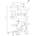
- FIG. 1 is a schematic diagram showing a carbon dioxide recovery system in the first embodiment.
- the carbon dioxide recovery system 1 includes a supply route 2, a carbon dioxide adsorption unit 3, a derivation route 4, a regeneration route 5, a circulation route 6, a carbon dioxide separator 7, and a heat pump. It includes a unit (heat exchange unit) 8, an introduction path 9, a compressor 10, and a pressure reducer 11.
- the supply route 2 is connected to the processing area 31 of the carbon dioxide adsorption unit 3.
- the supply path 2 guides air (fluid to be processed) such as outside air to the processing area 31 .
- the supply path 2 is provided with a blower 21 for sending air to the processing area 31, for example.
- the carbon dioxide adsorption unit 3 includes a first region 31A and a second region 32A.
- the first area 31A is the processing area 31.
- the second area 32A is the reproduction area 32.
- the processing area 31 includes, for example, an adsorbent and a container containing the adsorbent.
- the regeneration area 32 includes, for example, an adsorbent to be regenerated and a container containing the adsorbent.
- the adsorbent examples include amine, silica gel, zeolite, activated carbon, diatomaceous earth, and alumina. Specifically, by adsorbing carbon dioxide contained in the air onto an adsorbent, it can be separated from other components.
- the adsorbent may be granular, powdered, etc. The granules are, for example, bead-like (spherical), pellet-like (cylindrical), and the like.
- the adsorbent When using a powdered adsorbent, the adsorbent may be supported on the surface of the base material.
- the base material may have a honeycomb shape.
- At least a portion of the carbon dioxide contained in the air is removed by adsorption, so air with a reduced concentration of carbon dioxide is obtained.
- the regeneration region 32 regenerates the adsorbent that adsorbed carbon dioxide in the processing region 31 using the regeneration fluid F1.
- the regeneration region 32 has a function of desorbing carbon dioxide from the adsorbent.
- the regeneration area 32 includes, for example, a heating device that heats the adsorbent. The heating device desorbs carbon dioxide from the adsorbent by heating the adsorbent in the presence of the regeneration fluid F1. The adsorbent is regenerated by desorption of carbon dioxide.
- the regeneration fluid F1 containing carbon dioxide desorbed from the adsorbent is discharged from the regeneration region 32 as a "regeneration discharge fluid F2."
- the regeneration area 32 may be equipped with a pressure reducing device such as a pressure reducing pump.
- the decompression device promotes desorption of carbon dioxide from the adsorbent by placing the adsorbent under reduced pressure.
- the derivation path 4 is connected to the processing area 31.
- the derivation path 4 supplies the living space (supplied space) 100 with air in which the concentration of carbon dioxide has been reduced by the treatment region 31 .
- the regeneration path 5 is connected to the regeneration region 32 of the carbon dioxide adsorption unit 3 and the carbon dioxide separator 7.
- the regeneration path 5 leads the regeneration fluid F1 from the carbon dioxide separator 7 to the regeneration area 32.
- Examples of the regeneration fluid F1 include nitrogen (N 2 ), hydrogen (H 2 ), and methane.
- the circulation path 6 is connected to the regeneration area 32 of the carbon dioxide adsorption unit 3 and the carbon dioxide separator 7.
- the circulation path 6 leads the regeneration discharge fluid F2 discharged from the regeneration region 32 to the carbon dioxide separator 7.
- the carbon dioxide separator 7 separates at least a portion of the carbon dioxide contained in the recycled discharge fluid F2 using a separation method such as liquefaction separation, membrane separation, or adsorption separation.
- the carbon dioxide separator 7 may employ one of these separation techniques, or may use a combination of two or more.
- the carbon dioxide separator 7 using liquefaction separation for example, liquefies a specific component and separates it from other components (gas). Specifically, for example, carbon dioxide is liquefied under high pressure and low temperature conditions and separated from other components (gases).
- the carbon dioxide separator 7 using membrane separation uses, for example, a separation membrane through which components with small molecular sizes can pass through to separate specific components from other components.
- a separation membrane that selectively permeates carbon dioxide is used. This separation membrane separates carbon dioxide from a mixed fluid containing carbon dioxide and other components (nitrogen, hydrogen, methane, etc.).
- the separation membrane include organic membranes (dendrimer membranes, etc.) and inorganic membranes (zeolite membranes, silica membranes, carbon membranes, etc.).
- the carbon dioxide separator 7 that uses adsorption separation, for example, separates specific components by adsorbing them onto an adsorbent.
- the adsorbent include amine, silica gel, zeolite, activated carbon, diatomaceous earth, and alumina.
- carbon dioxide can be separated from other components by adsorbing it on an adsorbent.
- the regeneration discharge fluid F2 whose concentration of carbon dioxide has been reduced by separating the carbon dioxide, is led out from the carbon dioxide separator 7 through the regeneration path 5 as the "regeneration fluid F1.”
- the heat pump unit 8 includes a heater (first heat exchanger) 81, an expander 82, a cooler (second heat exchanger) 83, a compressor 84, and a circulation path 85.
- the heater 81 heats the regeneration fluid F1 by heat exchange with the heat medium fluid F3.
- Expander 82 lowers the pressure of heat transfer fluid F3.
- the cooler 83 cools the regenerated discharge fluid F2 by heat exchange with the heat medium fluid F3.
- Compressor 84 increases the pressure of heat transfer fluid F3.
- a heater 81 , an expander 82 , a cooler 83 , and a compressor 84 are provided in a circulation path 85 .
- the circulation route 85 is a circular route.
- the circulation path 85 circulates the heat medium fluid F3.
- the heat medium fluid F3 circulates through the heater 81, the expander 82, the cooler 83, and the compressor 84 in this order.
- Examples of the heat transfer fluid F3 include carbon dioxide, alternative fluorocarbons, propane, dimethyl ether, and the like.
- carbon dioxide is used as the heat transfer fluid F3, an appropriate heating temperature by the heater 81 (for example, 90°C to 120°C) and an appropriate cooling temperature by the cooler 83 (for example, -30°C to -20°C) This can be realized by applying the existing heat pump unit 8.
- the heat pump unit 8 may constitute an air conditioner, for example.
- the air conditioner performs at least one of cooling and heating using heat absorption or heat radiation of the heat medium fluid F3.
- the heater 81 is installed, for example, in one of the indoor unit and the outdoor unit.
- the cooler 83 is installed, for example, in the other of the indoor unit and the outdoor unit.
- the heat pump unit 8 may constitute, for example, a refrigerator-freezer device.
- the refrigerator-freezer device uses the heat absorption of the heat transfer fluid F3 to perform cooling by the cooler 83.
- the introduction route 9 is connected to the supply route 2.
- the introduction route 9 introduces indoor air discharged from the living space 100 into the supply route 2 .
- the compressor 10 is provided in the circulation path 6.
- Compressor 10 increases the pressure of regeneration discharge fluid F2.
- the pressure reducer 11 is provided in the regeneration path 5.
- the pressure reducer 11 reduces the pressure of the regeneration fluid F1.
- a cooler may be provided on the downstream side of the compressor 10 in order to lower the temperature of the regenerated discharge fluid F2, which has become high in temperature due to pressure increase by the compressor 10.
- the supply path 2 guides air such as outside air to the processing area 31 of the carbon dioxide adsorption unit 3 .
- air In the treatment region 31, at least a portion of the carbon dioxide contained in the air is removed by adsorbing the carbon dioxide contained in the air into an adsorbent.
- the air with a lower concentration of carbon dioxide is supplied to the living space (supplied space) 100 through the derivation path 4 .
- the process of removing at least a portion of carbon dioxide by adsorption in the treatment region 31 is referred to as an "adsorption process.”
- the adsorbent that has adsorbed carbon dioxide in the treatment area 31 is regenerated in the regeneration area 32.
- carbon dioxide is desorbed from the adsorbent in the presence of the regeneration fluid F1.
- the adsorbent is regenerated by desorption of carbon dioxide.
- the regeneration fluid F1 containing carbon dioxide desorbed from the adsorbent is discharged from the regeneration region 32 as a "regeneration discharge fluid F2.”
- the process of regenerating the adsorbent in the regeneration area 32 is referred to as a "regeneration process.”
- the adsorbent can be replaced between the processing region 31 and the regeneration region 32.
- the adsorbent in the processing area 31 is moved to the regeneration area 32 along with the container, and the adsorbent regenerated in the regeneration area 32 is moved to the processing area 31 along with the container. In this way, the processing area and the reproduction area can be switched.
- the processing area and reproduction area can also be switched by changing the route.
- the first region 31A (left portion in FIG. 1 ) of the carbon dioxide adsorption unit 3 is the processing region 31 .
- the supply path 2 and the derivation path 4 are connected to the first region 31A.
- the second area 32A (the right part in FIG. 1) is the reproduction area 32.
- the regeneration path 5 and the circulation path 6 are connected to the second region 32A.
- the supply route 2 and the outlet route 4 are connected to the second region 32A by operating a valve provided in a branch route (not shown) or the like.
- the regeneration path 5 and the circulation path 6 are connected to the first region 31A.
- the first area 31A becomes a reproduction area.
- the second area 32A becomes a processing area. In this way, it is possible to switch between the processing area and the reproduction area.
- the first region 31A can also be returned to the processing region by operating a valve or the like.
- the second area 32A can also be returned to the reproduction area.
- the regeneration discharge fluid F2 is led out of the regeneration area 32 through the circulation path 6.
- the pressure of the regenerated discharge fluid F2 is increased by the compressor 10.
- the regenerated discharge fluid F2 is cooled by heat exchange with the heat transfer fluid F3 in the cooler 83.
- the cooler 83 can, for example, cool the regenerated discharge fluid F2 in the carbon dioxide separator 7 to a temperature that corresponds to the specifications of the carbon dioxide separator 7, which will be described later.
- Regeneration discharge fluid F2 is led to carbon dioxide separator 7.
- the carbon dioxide separator 7 separates at least a portion of the carbon dioxide contained in the recycled discharge fluid F2 using a separation method such as liquefaction separation, membrane separation, or adsorption separation.
- the concentrated carbon dioxide is recovered through the recovery path 71.
- the regeneration discharge fluid F2 whose concentration of carbon dioxide has been reduced by separating the carbon dioxide, is led out from the carbon dioxide separator 7 through the regeneration path 5 as the "regeneration fluid F1.”
- the regeneration fluid F1 is heated by heat exchange with the heat medium fluid F3 in the heater 81.
- the heater 81 can heat the regeneration fluid F1 so that the temperature of the regeneration fluid F1 in the regeneration region 32 is 90° C. to 120° C., for example.
- the pressure of the regeneration fluid F1 is reduced in the pressure reducer 11 as necessary.
- the regeneration fluid F1 is introduced into the regeneration region 32 through the regeneration path 5.
- the heat medium fluid F3 circulates through the circulation path 85.
- the heat medium fluid F3 is cooled by heat exchange with the regeneration fluid F1 in the heater 81.
- the heat medium fluid F3 is depressurized by the expander 82.
- the heat medium fluid F3 is heated in the cooler 83 by heat exchange with the regenerated discharge fluid F2.
- the heat medium fluid F3 heads toward the heater 81. In this way, the heat transfer fluid F3 heats the regeneration fluid F1 and cools the regeneration discharge fluid F2.
- the carbon dioxide recovery system 1 includes a circulation path 6 that guides the regeneration exhaust fluid F2 from the regeneration area 32, and a carbon dioxide separator 7 that generates a regeneration fluid F1 with a low carbon dioxide concentration from the regeneration exhaust fluid F2. Since the carbon dioxide recovery system 1 circulates the regeneration fluid F1, the carbon dioxide recovery efficiency in the carbon dioxide separator 7 can be improved.
- the carbon dioxide recovery system 1 Since the carbon dioxide recovery system 1 circulates and uses the regeneration fluid F1 and the regeneration exhaust fluid F2, it can effectively utilize the thermal energy of the regeneration fluid F1 and the regeneration exhaust fluid F2. Therefore, the energy efficiency of the entire system can be improved.
- the carbon dioxide recovery system 1 recovers carbon dioxide from the air using the carbon dioxide adsorption unit 3 and guides the regeneration exhaust fluid F2 containing carbon dioxide to the carbon dioxide separator 7, so that the carbon dioxide recovery efficiency can be improved.
- the carbon dioxide recovery system 1 includes a compressor 10, a heater 81, and a cooler 83.
- the heater 81 can efficiently regenerate the adsorbent by heating the regeneration fluid F1 and making the temperature within the regeneration region 32 appropriate.
- the compressor 10 can efficiently separate carbon dioxide in the carbon dioxide separator 7 by increasing the pressure of the regenerated discharge fluid F2.
- the cooler 83 can efficiently separate carbon dioxide by cooling the regenerated discharge fluid F2 and adjusting the temperature within the carbon dioxide separator 7. In the carbon dioxide recovery system 1, the compressor 10 and the cooler 83 can reduce the volume of the regenerated discharge fluid F2, so that the device can be downsized.
- the heater 81 heats the regeneration fluid F1 by heat exchange with the heat medium fluid F3.
- the cooler 83 cools the regenerated discharge fluid F2 by heat exchange with the heat medium fluid F3. Since the carbon dioxide recovery system 1 exchanges heat with the regeneration fluid F1 and the regeneration discharge fluid F2 via the common heat medium fluid F3, energy efficiency can be improved.
- the carbon dioxide separator 7 using liquefaction separation can efficiently separate carbon dioxide.
- the carbon dioxide separator 7 that uses liquefaction separation can reduce the volume of carbon dioxide by liquefaction, so the device can be downsized.
- the carbon dioxide separator 7 using membrane separation can efficiently separate carbon dioxide.
- the carbon dioxide separator 7 using membrane separation has fewer restrictions on pressure, temperature, etc. than when using other separation methods. Therefore, energy for pressurization, cooling, etc. can be suppressed. Therefore, carbon dioxide can be recovered at low cost.
- the carbon dioxide recovery system 1 can be constructed at low cost.
- the heater 81 and the cooler 83 may constitute at least an air conditioner. In that case, since the carbon dioxide recovery system 1 can be constructed using the heater 81 and cooler 83 of the air conditioner, the cost can be reduced compared to the case where a dedicated heater and cooler are used.
- the heater 81 and the cooler 83 may constitute at least a refrigerator-freezer device. In that case, since the carbon dioxide recovery system 1 can be constructed using the heater 81 and cooler 83 of the refrigerator/freezer device, costs can be reduced compared to the case where a dedicated heater and cooler are used.
- the heater 81 and the cooler 83 may constitute both an air conditioner and a refrigerator-freezer device.
- Embodiment 2 Next, a carbon dioxide recovery system according to Embodiment 2 will be described. Since the carbon dioxide recovery system according to this embodiment has the same configuration as the first embodiment, the differences from the first embodiment will mainly be explained. Components that are the same as those in Embodiment 1 are given the same reference numerals and descriptions thereof will be omitted.
- FIG. 2 is a schematic diagram of a part of the carbon dioxide recovery system according to the second embodiment.
- the carbon dioxide recovery system 101 includes a heat pump unit 108 instead of the heat pump unit 8 (see FIG. 1).
- the heat pump unit 108 differs from the heat pump unit 8 (see FIG. 1) in that it includes a plurality of compressors 184A and 184B instead of the compressor 84 (see FIG. 1).
- Compressors 184A and 184B are provided in circulation path 85.
- Compressor 184A is first compressor 184A.
- Compressor 184B is a second compressor 184B.
- the second compressor 184B is located downstream of the first compressor 184A in the flow direction of the heat transfer fluid F3.
- the first compressor 184A and the second compressor 184B are arranged in series in the circulation path 85.
- the heat pump unit 108 since the heat pump unit 108 includes a plurality of compressors 184A and 184B, the pressure of the heat medium fluid F3 can be increased. Therefore, the operating range of heating and cooling in the heat pump unit 108 can be expanded. Therefore, the performance as a carbon dioxide recovery system can be improved and carbon dioxide can be recovered efficiently.
- the number of compressors in the heat pump unit 108 is two, but the number of compressors is not limited to two.
- the number of compressors may be plural (any number greater than or equal to 2).
- Embodiment 3 Next, a carbon dioxide recovery system according to Embodiment 3 will be explained. Components that are the same as those in other embodiments are designated by the same reference numerals and description thereof will be omitted.
- FIG. 3 is a schematic diagram of a part of the carbon dioxide recovery system according to the third embodiment.
- the carbon dioxide recovery system 201 includes a heat pump unit 208 instead of the heat pump unit 8 (see FIG. 1).
- the heat pump unit 208 includes a heater (first heat exchanger) 281, a first expander 282, an intermediate heat exchanger 287, a first compressor 284, a first circulation path 285, and a second expander 288. , a cooler (second heat exchanger) 283, a second compressor 289, and a second circulation path 290.
- the heater 281 heats the regeneration fluid F1 by heat exchange with the first heat medium fluid F3A.
- the first expander 282 lowers the pressure of the first heat transfer fluid F3A.
- Intermediate heat exchanger 287 cools second heat medium fluid F3B by heat exchange with first heat medium fluid F3A.
- the first compressor 284 increases the pressure of the first heat transfer fluid F3A.
- the heater 281, the first expander 282, the intermediate heat exchanger 287, and the first compressor 284 are provided in the first circulation path 285.
- the first circulation route 285 is a circular route.
- the first circulation path 285 circulates the first heat medium fluid F3A through the heater 281, the first expander 282, the intermediate heat exchanger 287, and the first compressor 284 in this order.
- the second expander 288 lowers the pressure of the second heat transfer fluid F3B.
- the cooler 283 cools the regeneration discharge fluid F2 by heat exchange with the second heat medium fluid F3B.
- the second compressor 289 increases the pressure of the second heat transfer fluid F3B.
- Intermediate heat exchanger 287, second expander 288, cooler 283, and second compressor 289 are provided in second circulation path 290.
- the second circulation route 290 is a circular route.
- the second circulation path 290 circulates the second heat medium fluid F3B through the intermediate heat exchanger 287, the second expander 288, the cooler 283, and the second compressor 289 in this order.
- the first heat medium fluid F3A and the second heat medium fluid F3B have different physical properties such as boiling points.
- Examples of the first heat transfer fluid F3A include carbon dioxide.
- Examples of the second heat transfer fluid F3B include a fluorocarbon substitute.
- the second heat transfer fluid F3B is operated at a lower temperature than the first heat transfer fluid F3A, for example.
- a portion (first portion) through which the first heat medium fluid F3A flows can be constructed using, for example, a heat pump for a water heater.
- the first portion includes, for example, a heater 281, a first expander 282, a first compressor 284, and a first circulation path 285.
- a portion (second portion) of the heat pump unit 208 through which the second heat medium fluid F3B flows can be constructed using, for example, a heat pump for freezing and refrigeration.
- the second portion includes, for example, a second expander 288, a cooler 283, a second compressor 289, and a second circulation path 290.
- Intermediate heat exchanger 287 is included in one of the first section and the second section.
- the carbon dioxide recovery system 201 includes a heat pump unit 208 having a heater 281, an intermediate heat exchanger 287, and a cooler 283. Since the heat pump unit 208 uses the first heat medium fluid F3A and the second heat medium fluid F3B, the operating range of heating and cooling can be expanded. Therefore, the performance as a carbon dioxide recovery system can be improved and carbon dioxide can be recovered efficiently.
- Embodiment 4 Next, a carbon dioxide recovery system according to Embodiment 4 will be described. Components that are the same as those in other embodiments are designated by the same reference numerals and description thereof will be omitted.
- FIG. 4 is a schematic diagram of a carbon dioxide recovery system according to Embodiment 4. As shown in FIG. 4, the carbon dioxide recovery system 301 differs from the carbon dioxide recovery system 1 (see FIG. 1) in that an air purifier 312 is provided in the introduction path 9.
- the air purifier 312 purifies the air by collecting floating substances such as pollen, dust, viruses, mold, bacteria, house dust, smoke, odor substances, and volatile chemicals.
- the air cleaner 312 includes, for example, a filter that collects suspended substances.
- the air cleaner 312 may include an electric field generating device that generates an electric field between electrodes. The electric field generating device can kill or inactivate pollen, viruses, mold, bacteria, and the like.
- the carbon dioxide recovery system 301 includes the air cleaner 312, it can purify the indoor air discharged from the living space 100 and introduce it into the supply route 2. Therefore, the cleanliness of the air supplied to the living space 100 can be increased.
- the carbon dioxide recovery system 301 can improve the carbon dioxide recovery efficiency in the carbon dioxide adsorption unit 3 because the air supplied to the carbon dioxide adsorption unit 3 is clean.
- Embodiment 5 Next, a carbon dioxide recovery system according to Embodiment 5 will be described. Components that are the same as those in other embodiments are designated by the same reference numerals and description thereof will be omitted.
- FIG. 5 is a schematic diagram of a carbon dioxide recovery system according to Embodiment 5.
- the carbon dioxide recovery system 401 differs from the carbon dioxide recovery system 1 (see FIG. 1) in that an exhaust path 413 is connected to the derivation path 4.
- the exhaust path 413 can exhaust part of the air flowing through the outlet path 4 to the outside of the system.
- the gas exhausted from the exhaust path 413 is emitted into the atmosphere, for example.
- the carbon dioxide recovery system 401 can take in outside air from the supply route 2 by discharging a portion of the air flowing through the derivation route 4 from the exhaust route 413. By performing ventilation by discharging and taking in air, the cleanliness of the air within the living space 100 can be increased.
- the carbon dioxide recovery system 401 discharges the gas after recovering carbon dioxide into the atmosphere from the exhaust path 413, so that the amount of carbon dioxide emissions can be kept low. Therefore, it is suitable in terms of environmental conservation.
- Embodiment 6 Next, a carbon dioxide recovery system according to Embodiment 6 will be described. Components that are the same as those in other embodiments are designated by the same reference numerals and description thereof will be omitted.
- FIG. 6 is a schematic diagram of a carbon dioxide recovery system according to Embodiment 6.
- the carbon dioxide recovery system 501 has the following features: an air purifier 312 is provided in the introduction route 9, and an exhaust route 413 is connected to the outlet route 4. 1 (see Figure 1).
- the carbon dioxide recovery system 501 includes the air cleaner 312, clean air can be introduced into the supply route 2. Since the carbon dioxide recovery system 501 includes an exhaust path 413, ventilation can be performed. Therefore, the cleanliness of the air within the living space 100 can be increased. Since the carbon dioxide recovery system 501 discharges the gas after recovering carbon dioxide into the atmosphere from the exhaust path 413, the amount of carbon dioxide emissions can be kept low. Therefore, it is suitable in terms of environmental conservation.
- Embodiment 7 Next, a carbon dioxide recovery system according to Embodiment 7 will be described. Components that are the same as those in other embodiments are designated by the same reference numerals and description thereof will be omitted.
- FIG. 7 is a schematic diagram of a carbon dioxide recovery system according to Embodiment 7.
- the carbon dioxide recovery system 601 includes a carbon dioxide adsorption section 603 instead of the carbon dioxide adsorption section 3 (see FIG. 1).
- the carbon dioxide adsorption unit 603 includes a first processing area 31 , a second processing area 633 , and a regeneration area 32 .
- the first processing area 31 has the same configuration as the processing area 31 (see FIG. 1).
- the second treatment area 633 like the first treatment area 31, includes an adsorbent.
- the adsorbent in the second treatment area 633 may be the same as the adsorbent in the first treatment area 31 .
- the adsorbents in the first treatment area 31 and the second treatment area 633 can be regenerated by a regeneration process.
- the second processing area 633 is connected to the introduction path 9.
- the introduction path 9 guides the air exhausted from the living space 100 to the second treatment area 633.
- the second processing region 633 removes at least a portion of carbon dioxide contained in the air by adsorption.
- the air with reduced carbon dioxide concentration is exhausted from the second processing area 633 to the outside of the system through the exhaust path 634.
- the carbon dioxide recovery system 601 since the carbon dioxide recovery system 601 includes the second processing region 633, it can recover carbon dioxide contained in the air exhausted from the living space 100. Therefore, the carbon dioxide recovery efficiency can be increased. In the carbon dioxide recovery system 601, the air exhausted from the living space 100 is not reused, but is exhausted outside the system through the exhaust path 634. Therefore, the risk of airborne infection and droplet infection of infectious diseases such as viruses can be reduced. Furthermore, the cleanliness of the air within the living space 100 can be increased. Since the carbon dioxide recovery system 601 discharges the gas after recovering carbon dioxide into the atmosphere from the exhaust path 413, the amount of carbon dioxide emissions can be kept low. Therefore, it is suitable in terms of environmental conservation.
- Embodiment 8 Next, a carbon dioxide recovery system according to Embodiment 8 will be described. Components that are the same as those in other embodiments are designated by the same reference numerals and description thereof will be omitted.
- FIG. 8 is a schematic diagram of a carbon dioxide recovery system according to Embodiment 8.
- the carbon dioxide recovery system 701 differs from the carbon dioxide recovery system 601 (see FIG. 7) in that a heat exchanger 714 is provided.
- the heat exchanger 714 is provided across the outlet path 4 and the introduction path 9.
- the heat exchanger 714 exchanges heat and humidity between the air supplied to the living space 100 through the outlet path 4 and the air led out from the living space 100 through the introduction path 9.
- the heat exchanger 714 can adjust the temperature and humidity of the air supplied to the living space 100 according to the environment within the living space 100.
- the carbon dioxide recovery system 701 includes a heat exchanger 714, the temperature of the air supplied to the living space 100 through the outlet path 4 can be adjusted by heat exchange with the exhaust air, and the temperature and humidity can be optimized. can. Therefore, energy efficiency can be improved.
- the carbon dioxide separator prefferably employs one or both of liquefaction separation and membrane separation.
- liquefaction separation and membrane separation there are suitable for the carbon dioxide separator to employ one or both of liquefaction separation and membrane separation.
- configuration examples of carbon dioxide recovery systems will be shown for cases in which liquefaction separation is employed, membrane separation is employed, and both liquefaction separation and membrane separation are employed.
- Embodiment 9 A carbon dioxide recovery system according to Embodiment 9 will be described. Components that are the same as those in other embodiments are designated by the same reference numerals and description thereof will be omitted.
- FIG. 9 is a schematic diagram of a carbon dioxide recovery system according to Embodiment 9.
- the carbon dioxide separator 7 is a liquefaction separator that separates carbon dioxide by liquefaction separation. Since the carbon dioxide separator 7 is a liquefaction separator, high pressure and low temperature are required.
- the regenerated discharge fluid F2 is brought to a high pressure by the compressor 10.
- the regenerated discharge fluid F2 is brought to a low temperature by the cooler 83.
- the conditions for liquefying carbon dioxide are, for example, a temperature of -20 to -30°C and a pressure of 2 MPa.
- the carbon dioxide recovery system 801 includes a cooler 815.
- Cooler 815 is provided downstream of compressor 10 in circulation path 6 .
- Cooler 815 is provided between compressor 10 and cooler 83, for example.
- the cooler 815 is, for example, a water-cooled cooler.
- the cooler 815 cools the regenerated discharge fluid F2 by heat exchange with the refrigerant (water). Although the temperature of the regeneration discharge fluid F2 increases due to the pressure increase by the compressor 10, the cooler 815 lowers the temperature of the regeneration discharge fluid F2. Therefore, the load on the cooler 83 can be reduced.
- the carbon dioxide separator 7 liquefies and separates at least a portion of the carbon dioxide contained in the regeneration exhaust fluid F2 that has passed through the cooler 83.
- the concentrated carbon dioxide is recovered through the recovery path 71.
- the carbon dioxide recovery system 801 employs liquefaction separation, carbon dioxide can be efficiently separated. Since the carbon dioxide recovery system 801 can reduce the volume of carbon dioxide by liquefying it, it is possible to downsize the device.
- cooler 815 has been described as a water-cooled cooler
- the cooling method of the cooler is not limited to this.
- cooling by circulating the regeneration fluid F1 may be adopted. Good too. Since the regeneration fluid F1 is thereby heated, a system with higher thermal efficiency is realized.
- Embodiment 10 Next, a carbon dioxide recovery system according to Embodiment 10 will be described. Components that are the same as those in other embodiments are designated by the same reference numerals and description thereof will be omitted.
- FIG. 10 is a schematic diagram of a carbon dioxide recovery system according to Embodiment 10.
- the carbon dioxide separator 907 is a membrane separator that separates carbon dioxide by membrane separation.
- the carbon dioxide separator 907 includes, for example, a separation membrane that selectively permeates carbon dioxide.
- the carbon dioxide separator 907 separates at least a portion of carbon dioxide contained in the regenerated discharge fluid F2 by membrane separation.
- the concentrated carbon dioxide is recovered through the recovery path 71.
- the carbon dioxide recovery system 901 employs membrane separation, carbon dioxide can be efficiently separated.
- the carbon dioxide recovery system 901 has fewer restrictions on pressure, temperature, etc. than when other separation methods are employed. Since energy for pressurization, cooling, etc. can be suppressed, carbon dioxide can be recovered at low cost.
- Embodiment 11 Next, a carbon dioxide recovery system according to Embodiment 11 will be described. Components that are the same as those in other embodiments are designated by the same reference numerals and description thereof will be omitted.
- FIG. 11 is a schematic diagram of a carbon dioxide recovery system according to Embodiment 11. As shown in FIG. 11, the carbon dioxide recovery system 1001 employs both liquefaction separation and membrane separation as carbon dioxide separation methods in the carbon dioxide separator.
- the carbon dioxide recovery system 1001 includes a supply route 2, a carbon dioxide adsorption unit 3, a derivation route 4, a regeneration route 5, a circulation route 6, a heat pump unit 8, an introduction route 9, and a first compressor 10. , the first cooler 1015, the first carbon dioxide separator 1007, the return route 1002, the second compressor 1010, the second cooler 1016, the second carbon dioxide separator 7, and the pressure reducer 11. , is provided.
- the first carbon dioxide separator 1007 and the second carbon dioxide separator 7 are examples of carbon dioxide separators.
- the carbon dioxide recovery system 1001 is a carbon dioxide recovery system in that it includes a first cooler 1015, a first carbon dioxide separator 1007, a return route 1002, a second compressor 1010, and a second cooler 1016. 1 (see Figure 1).
- the first cooler 1015 and the second cooler 1016 are, for example, water-cooled coolers.
- the first cooler 1015 and the second cooler 1016 cool the fluid by heat exchange with a refrigerant (water).
- the first carbon dioxide separator 1007 is a membrane separator.
- the first carbon dioxide separator 1007 has, for example, a separation membrane that selectively permeates carbon dioxide.
- the second carbon dioxide separator 7 is a liquefaction separator.
- the return path 1002 connects the non-permeate side outlet of the first carbon dioxide separator 1007 and the circulation path 6 (a position upstream of the first compressor 10).
- the pressure of the regenerated discharge fluid F2 is increased by the first compressor 10, and then cooled by the first cooler 1015 and guided to the first carbon dioxide separator 1007.
- the carbon dioxide contained in the regeneration exhaust fluid F2 is concentrated by the first carbon dioxide separator 1007.
- the permeate fluid F4 enriched with carbon dioxide heads to the second compressor 1010.
- the non-permeate fluid F5 that has not passed through the separation membrane of the first carbon dioxide separator 1007 is returned to the circulation path 6 (a position upstream of the first compressor 10) via the return path 1002. Thereby, the carbon dioxide separation efficiency in the first carbon dioxide separator 1007 can be increased.
- the second compressor 1010 After the pressure of the permeate side fluid F4 is increased by the second compressor 1010, it is cooled by the second cooler 1016 and the cooler 83, and then guided to the second carbon dioxide separator 7.
- the second carbon dioxide separator 7 liquefies and separates at least a portion of carbon dioxide contained in the permeate fluid F4.
- the concentrated carbon dioxide is recovered through the recovery path 71.
- the carbon dioxide recovery system 1001 can improve carbon dioxide recovery efficiency by employing both liquefaction separation and membrane separation.
- the first cooler 1015 and the second cooler 1016 have been described as water-cooled, but are not limited to this.
- cooling by circulating the regeneration fluid F1 may be adopted. Good too. Since the regeneration fluid F1 is thereby heated, a system with higher thermal efficiency is realized.
- Embodiment 12 Next, a carbon dioxide recovery system according to Embodiment 12 will be described. Components that are the same as those in other embodiments are designated by the same reference numerals and description thereof will be omitted.
- FIG. 12 is a schematic diagram of a carbon dioxide recovery system according to Embodiment 12.
- the carbon dioxide recovery system 1101 differs from the carbon dioxide recovery system 1001 (see FIG. 11) in that it has a return route 1102 instead of the return route 1002 (see FIG. 11).
- the return path 1102 connects the non-permeate side exit of the first carbon dioxide separator 1007 and the regeneration path 5 (a position upstream of the heater 81).
- the non-permeate side fluid F5 led out from the first carbon dioxide separator 1007 is guided to the regeneration path 5 via the return path 1102.
- the non-permeate side fluid F5 is used as a part of the regeneration fluid F1.
- the carbon dioxide recovery system 1101 can improve carbon dioxide recovery efficiency by employing both liquefaction separation and membrane separation. Since the carbon dioxide recovery system 1101 performs membrane separation prior to liquefaction separation, the energy required for cooling for liquefaction separation can be suppressed. Therefore, carbon dioxide can be recovered at low cost. In the carbon dioxide recovery system 1101, the non-permeate fluid F5 with a lower concentration of carbon dioxide is used as the regeneration fluid F1, so energy efficiency can be improved.
- the circulation path 6 may be provided with one or more concentrators.
- the concentrator increases the concentration of carbon dioxide in the regenerated discharge fluid F2 by, for example, liquefaction separation, membrane separation, adsorption separation, or the like. Therefore, the energy efficiency in the carbon dioxide separator 7 can be improved.
- a concentrator may be provided in the supply route 2.
- the pressure reducer 11 is provided downstream of the heater 81, the present invention is not limited thereto, and may be provided upstream of the heater 81 depending on the specifications of the system equipment.
- a heat exchanger such as a heater, a cooler, or an intermediate heat exchanger
- a known heat exchanger can be used.
- the heat exchanger for example, a shell-and-tube heat exchanger, a plate heat exchanger, a coil heat exchanger, a double-tube heat exchanger, a spiral heat exchanger, etc. can be used.
- air is illustrated as the fluid to be treated, the carbon dioxide recovery system of the embodiment can also be applied to fluids to be treated other than air (nitrogen gas, hydrogen gas, oxygen gas, methane, etc.).
Landscapes
- Chemical & Material Sciences (AREA)
- Engineering & Computer Science (AREA)
- Chemical Kinetics & Catalysis (AREA)
- Analytical Chemistry (AREA)
- General Chemical & Material Sciences (AREA)
- Oil, Petroleum & Natural Gas (AREA)
- Organic Chemistry (AREA)
- Health & Medical Sciences (AREA)
- Environmental & Geological Engineering (AREA)
- Biomedical Technology (AREA)
- Inorganic Chemistry (AREA)
- Separation Of Gases By Adsorption (AREA)
- Carbon And Carbon Compounds (AREA)
Abstract
Description
図1は、実施の形態1における二酸化炭素回収システムを示す模式図である。
図1に示すように、二酸化炭素回収システム1は、供給経路2と、二酸化炭素吸着部3と、導出経路4と、再生用経路5と、循環経路6と、二酸化炭素分離器7と、ヒートポンプユニット(熱交換ユニット)8と、導入経路9と、圧縮機10と、減圧器11とを備える。
加熱器81は、熱媒体流体F3との熱交換によって再生用流体F1を加熱する。
膨張器82は、熱媒体流体F3の圧力を低くする。
冷却器83は、熱媒体流体F3との熱交換によって再生排出流体F2を冷却する。
圧縮機84は、熱媒体流体F3の圧力を高める。
加熱器81、膨張器82、冷却器83および圧縮機84は、循環経路85に設けられている。
熱媒体流体F3として二酸化炭素を用いる場合は、加熱器81による適切な加熱温度(例えば、90℃~120℃)、および冷却器83による適切な冷却温度(例えば、-30℃~-20℃)を、既存のヒートポンプユニット8を応用することで実現できる。
圧縮機10は、循環経路6に設けられている。圧縮機10は再生排出流体F2の圧力を高める。
減圧器11は、再生用経路5に設けられている。減圧器11は再生用流体F1を減圧する。
圧縮機10の下流側には、圧縮機10による昇圧によって高温となった再生排出流体F2の温度を低下させるため、冷却器を設けてもよい。
供給経路2によって、外気などの空気を二酸化炭素吸着部3の処理領域31に導く。処理領域31では、空気に含まれる二酸化炭素を吸着剤に吸着させることによって、二酸化炭素の少なくとも一部を除去する。二酸化炭素の濃度が低くなった空気は、導出経路4によって居住空間(被供給空間)100に供給される。
処理領域31において二酸化炭素の少なくとも一部を吸着により除去する工程を「吸着工程」という。
再生領域32において吸着剤を再生する工程を「再生工程」という。
処理領域31で二酸化炭素を吸着した吸着剤を再生領域32で再生する際には、処理領域31と再生領域32との間で、吸着剤を入れ替えることができる。例えば、処理領域31の吸着剤を容器ごと再生領域32に移動させるとともに、再生領域32で再生した吸着剤を容器ごと処理領域31に移動させる。このようにして、処理領域と再生領域とを切り替えることができる。
再生排出流体F2は、二酸化炭素分離器7に導かれる。
二酸化炭素回収システム1は、二酸化炭素吸着部3によって空気から二酸化炭素を回収し、二酸化炭素を含む再生排出流体F2を二酸化炭素分離器7に導くため、二酸化炭素の回収効率を高めることができる。
二酸化炭素回収システム1は、圧縮機10および冷却器83によって再生排出流体F2の体積を小さくできるため、装置の小型化を図ることができる。
膜分離を用いた二酸化炭素分離器7は、二酸化炭素の分離を効率よく行うことができる。膜分離を用いた二酸化炭素分離器7は、他の分離手法を採用する場合に比べ、圧力、温度などの制約が少ない。そのため、加圧、冷却などのためのエネルギーを抑制できる。よって、低コストで二酸化炭素を回収することができる。
加熱器81および冷却器83は、少なくとも冷凍冷蔵庫装置を構成してもよい。その場合、冷凍冷蔵庫装置の加熱器81および冷却器83を利用して二酸化炭素回収システム1を構築できるため、専用の加熱器および冷却器を用いる場合に比べ、低コスト化が可能である。
加熱器81および冷却器83は、空気調和装置と冷凍冷蔵庫装置の両方を構成してもよい。
次に、実施の形態2に係る二酸化炭素回収システムについて説明する。この実施の形態に係る二酸化炭素回収システムは、実施の形態1と共通の構成を有するため、主に、実施の形態1と異なる点を説明する。実施の形態1と同じ構成については、同じ符号を付して説明を省略する。
図2に示すように、二酸化炭素回収システム101は、ヒートポンプユニット8(図1参照)に代えてヒートポンプユニット108を備える。ヒートポンプユニット108は、圧縮機84(図1参照)に代えて複数の圧縮機184A,184Bを備える点で、ヒートポンプユニット8(図1参照)と異なる。圧縮機184A,184Bは、循環経路85に設けられている。圧縮機184Aは第1圧縮機184Aである。圧縮機184Bは第2圧縮機184Bである。第2圧縮機184Bは、第1圧縮機184Aに対して、熱媒体流体F3の流れ方向の下流側にある。第1圧縮機184Aと第2圧縮機184Bとは、循環経路85において直列に配置されている。
次に、実施の形態3に係る二酸化炭素回収システムについて説明する。他の実施の形態と同じ構成については、同じ符号を付して説明を省略する。
図3に示すように、二酸化炭素回収システム201は、ヒートポンプユニット8(図1参照)に代えてヒートポンプユニット208を備える。
ヒートポンプユニット208は、加熱器(第1熱交換器)281と、第1膨張器282と、中間熱交換器287と、第1圧縮機284と、第1循環経路285と、第2膨張器288と、冷却器(第2熱交換器)283と、第2圧縮機289と、第2循環経路290と、を備える。
第1膨張器282は、第1熱媒体流体F3Aの圧力を低くする。
中間熱交換器287は、第1熱媒体流体F3Aとの熱交換によって第2熱媒体流体F3Bを冷却する。
第1圧縮機284は、第1熱媒体流体F3Aの圧力を高める。
加熱器281、第1膨張器282、中間熱交換器287および第1圧縮機284は、第1循環経路285に設けられている。
第1循環経路285は、環状の経路である。第1循環経路285は、第1熱媒体流体F3Aを、加熱器281、第1膨張器282、中間熱交換器287、および第1圧縮機284をこの順に経由するように循環させる。
冷却器283は、第2熱媒体流体F3Bとの熱交換によって再生排出流体F2を冷却する。
第2圧縮機289は、第2熱媒体流体F3Bの圧力を高める。
中間熱交換器287、第2膨張器288、冷却器283および第2圧縮機289は、第2循環経路290に設けられている。
第2循環経路290は、環状の経路である。第2循環経路290は、第2熱媒体流体F3Bを、中間熱交換器287、第2膨張器288、冷却器283、および第2圧縮機289をこの順に経由するように循環させる。
ヒートポンプユニット208のうち、第2熱媒体流体F3Bが流れる部分(第2部分)は、例えば、冷凍冷蔵用のヒートポンプを利用して構築することができる。第2部分は、例えば、第2膨張器288、冷却器283、第2圧縮機289および第2循環経路290を含む。
中間熱交換器287は、第1部分と第2部分のうち一方に含まれる。
次に、実施の形態4に係る二酸化炭素回収システムについて説明する。他の実施の形態と同じ構成については、同じ符号を付して説明を省略する。
図4に示すように、二酸化炭素回収システム301は、導入経路9に空気清浄機312が設けられている点で、二酸化炭素回収システム1(図1参照)と異なる。
次に、実施の形態5に係る二酸化炭素回収システムについて説明する。他の実施の形態と同じ構成については、同じ符号を付して説明を省略する。
図5に示すように、二酸化炭素回収システム401は、導出経路4に排気経路413が接続されている点で、二酸化炭素回収システム1(図1参照)と異なる。排気経路413は、導出経路4を流れる空気の一部を系外に排出することができる。排気経路413から排出されたガスは、例えば、大気中に放出される。
次に、実施の形態6に係る二酸化炭素回収システムについて説明する。他の実施の形態と同じ構成については、同じ符号を付して説明を省略する。
図6に示すように、二酸化炭素回収システム501は、導入経路9に空気清浄機312が設けられている点、および、導出経路4に排気経路413が接続されている点で、二酸化炭素回収システム1(図1参照)と異なる。
次に、実施の形態7に係る二酸化炭素回収システムについて説明する。他の実施の形態と同じ構成については、同じ符号を付して説明を省略する。
図7に示すように、二酸化炭素回収システム601は、二酸化炭素吸着部3(図1参照)に代えて二酸化炭素吸着部603を備える。二酸化炭素吸着部603は、第1処理領域31と、第2処理領域633と、再生領域32とを備える。
第1処理領域31は、処理領域31(図1参照)と同様の構成である。
第2処理領域633は、第1処理領域31と同様に、吸着剤を備える。第2処理領域633の吸着剤は、第1処理領域31の吸着剤と同じであってよい。
第1処理領域31および第2処理領域633の吸着剤は、再生工程によって再生することができる。
二酸化炭素回収システム601では、居住空間100から排出された空気を再利用せず、排気経路634を通して系外に排出する。そのため、ウイルス等による感染症の空気感染および飛沫感染のリスクを低減できる。また、居住空間100内の空気の清浄度を高めることができる。二酸化炭素回収システム601は、二酸化炭素を回収した後のガスを排気経路413から大気中に排出するため、二酸化炭素の排出量を低く抑えることができる。そのため、環境保全性の点で好適である。
次に、実施の形態8に係る二酸化炭素回収システムについて説明する。他の実施の形態と同じ構成については、同じ符号を付して説明を省略する。
図8に示すように、二酸化炭素回収システム701は、熱交換器714が設けられている点で、二酸化炭素回収システム601(図7参照)と異なる。熱交換器714は、導出経路4と導入経路9とに跨って設けられている。熱交換器714は、導出経路4によって居住空間100に供給される空気と、導入経路9によって居住空間100から導出される空気とを熱交換および湿度交換させる。熱交換器714は、居住空間100に供給される空気を、居住空間100内の環境に応じた温度および湿度とすることができる。
実施の形態9に係る二酸化炭素回収システムについて説明する。他の実施の形態と同じ構成については、同じ符号を付して説明を省略する。
図9に示すように、二酸化炭素回収システム801では、二酸化炭素分離器7は、液化分離によって二酸化炭素を分離する液化分離器である。二酸化炭素分離器7は液化分離器であるため、高圧かつ低温が求められる。再生排出流体F2は圧縮機10によって高圧とされる。再生排出流体F2は冷却器83によって低温とされる。二酸化炭素を液化する条件は、例えば、温度-20~-30℃、圧力2MPaである。
次に、実施の形態10に係る二酸化炭素回収システムについて説明する。他の実施の形態と同じ構成については、同じ符号を付して説明を省略する。
図10に示すように、二酸化炭素回収システム901では、二酸化炭素分離器907は、膜分離によって二酸化炭素を分離する膜分離器である。二酸化炭素分離器907は、例えば、二酸化炭素を選択的に透過させる分離膜を備える。二酸化炭素分離器907は、再生排出流体F2に含まれる二酸化炭素の少なくとも一部を、膜分離により分離する。濃縮された二酸化炭素は、回収経路71を通して回収される。
次に、実施の形態11に係る二酸化炭素回収システムについて説明する。他の実施の形態と同じ構成については、同じ符号を付して説明を省略する。
図11に示すように、二酸化炭素回収システム1001では、二酸化炭素分離器における二酸化炭素の分離手法として液化分離と膜分離の両方を採用する。
第1冷却器1015および第2冷却器1016は、例えば、水冷式の冷却器である。第1冷却器1015および第2冷却器1016は、冷媒(水)との熱交換によって流体を冷却する。
第1二酸化炭素分離器1007は、膜分離器である。第1二酸化炭素分離器1007は、例えば、二酸化炭素を選択的に透過させる分離膜を有する。第2二酸化炭素分離器7は、液化分離器である。
次に、実施の形態12に係る二酸化炭素回収システムについて説明する。他の実施の形態と同じ構成については、同じ符号を付して説明を省略する。
図12に示すように、二酸化炭素回収システム1101は、返送経路1002(図11参照)に代えて返送経路1102を有する点で、二酸化炭素回収システム1001(図11参照)と異なる。
返送経路1102は、第1二酸化炭素分離器1007の非透過側の出口と、再生用経路5(加熱器81より上流側の位置)とを接続する。第1二酸化炭素分離器1007から導出された非透過側流体F5は、返送経路1102によって再生用経路5に導かれる。非透過側流体F5は、再生用流体F1の一部として用いられる。
二酸化炭素回収システム1101では、二酸化炭素の濃度が低くなった非透過側流体F5を再生用流体F1として利用するため、エネルギー効率を高めることができる。
例えば、循環経路6には、1または複数の濃縮器を設けてもよい。濃縮器は、例えば、液化分離、膜分離、吸着分離などの手法によって、再生排出流体F2の二酸化炭素の濃度を高める。そのため、二酸化炭素分離器7におけるエネルギー効率を高めることができる。濃縮器は、供給経路2に設けてもよい。また、減圧器11は加熱器81の下流側に設けたが、これに限定されるものではなく、システム機器仕様に応じて、加熱器81の上流側に設けてもよい。
被処理流体としては空気を例示したが、実施の形態の二酸化炭素回収システムは、空気以外の被処理流体(窒素ガス、水素ガス、酸素ガス、メタンなど)に適用することもできる。
Claims (10)
- 空気を導く供給経路と、
前記空気に含まれる二酸化炭素を吸着剤に吸着させる処理領域、および再生用流体を用いて前記吸着剤を再生させる再生領域を有する二酸化炭素吸着部と、
前記処理領域によって二酸化炭素の濃度が低くなった前記空気を導く導出経路と、
前記再生用流体を前記再生領域に導く再生用経路と、
前記再生用流体によって前記吸着剤を再生させることにより排出された再生排出流体を導く循環経路と、
前記再生排出流体から二酸化炭素の少なくとも一部を分離することによって前記再生用流体を得る二酸化炭素分離器と、を備える、
二酸化炭素回収システム。 - 前記再生用流体を加熱する加熱器と、
前記再生排出流体を冷却する冷却器と、
前記再生排出流体の圧力を高める圧縮機と、をさらに備える、
請求項1に記載の二酸化炭素回収システム。 - 前記加熱器は、熱媒体流体との熱交換によって前記再生用流体を加熱し、
前記冷却器は、前記熱媒体流体との熱交換によって前記再生排出流体を冷却する、
請求項2に記載の二酸化炭素回収システム。 - 中間熱交換器をさらに備え、
前記加熱器は、第1熱媒体流体との熱交換によって前記再生用流体を加熱し、
前記中間熱交換器は、前記第1熱媒体流体との熱交換によって第2熱媒体流体を冷却し、
前記冷却器は、前記第2熱媒体流体との熱交換によって前記再生排出流体を冷却する、
請求項2に記載の二酸化炭素回収システム。 - 前記二酸化炭素分離器は、前記再生排出流体に含まれる二酸化炭素を液化分離によって分離する、
請求項1~4のうちいずれか1項に記載の二酸化炭素回収システム。 - 前記二酸化炭素分離器は、前記再生排出流体に含まれる二酸化炭素を膜分離によって分離する、
請求項1~4のうちいずれか1項に記載の二酸化炭素回収システム。 - 前記熱媒体流体は、二酸化炭素である、
請求項3に記載の二酸化炭素回収システム。 - 前記加熱器および前記冷却器は、少なくとも空気調和装置を構成する、
請求項3に記載の二酸化炭素回収システム。 - 前記加熱器および前記冷却器は、少なくとも冷凍冷蔵庫装置を構成する、
請求項3に記載の二酸化炭素回収システム。 - 前記導出経路に、前記導出経路を流れる前記空気の一部を排出する排気経路が接続されている、
請求項1~9のうちいずれか1項に記載の二酸化炭素回収システム。
Priority Applications (7)
| Application Number | Priority Date | Filing Date | Title |
|---|---|---|---|
| JP2023505683A JP7359991B1 (ja) | 2022-07-15 | 2022-07-15 | 二酸化炭素回収システム |
| PCT/JP2022/027794 WO2024013957A1 (ja) | 2022-07-15 | 2022-07-15 | 二酸化炭素回収システム |
| CN202280097087.1A CN119451737A (zh) | 2022-07-15 | 2022-07-15 | 二氧化碳回收系统 |
| US18/875,212 US20250375732A1 (en) | 2022-07-15 | 2022-07-15 | Carbon dioxide capture system |
| EP22951170.4A EP4556097A4 (en) | 2022-07-15 | 2022-07-15 | CARBON DIOXIDE CAPTURE SYSTEM |
| JP2023137418A JP7681071B2 (ja) | 2022-07-15 | 2023-08-25 | 二酸化炭素回収システム |
| JP2025004320A JP2025039798A (ja) | 2022-07-15 | 2025-01-10 | 二酸化炭素回収システム |
Applications Claiming Priority (1)
| Application Number | Priority Date | Filing Date | Title |
|---|---|---|---|
| PCT/JP2022/027794 WO2024013957A1 (ja) | 2022-07-15 | 2022-07-15 | 二酸化炭素回収システム |
Publications (1)
| Publication Number | Publication Date |
|---|---|
| WO2024013957A1 true WO2024013957A1 (ja) | 2024-01-18 |
Family
ID=88242182
Family Applications (1)
| Application Number | Title | Priority Date | Filing Date |
|---|---|---|---|
| PCT/JP2022/027794 Ceased WO2024013957A1 (ja) | 2022-07-15 | 2022-07-15 | 二酸化炭素回収システム |
Country Status (5)
| Country | Link |
|---|---|
| US (1) | US20250375732A1 (ja) |
| EP (1) | EP4556097A4 (ja) |
| JP (3) | JP7359991B1 (ja) |
| CN (1) | CN119451737A (ja) |
| WO (1) | WO2024013957A1 (ja) |
Families Citing this family (1)
| Publication number | Priority date | Publication date | Assignee | Title |
|---|---|---|---|---|
| JP2025113847A (ja) * | 2024-01-23 | 2025-08-04 | 本田技研工業株式会社 | 二酸化炭素回収装置 |
Citations (14)
| Publication number | Priority date | Publication date | Assignee | Title |
|---|---|---|---|---|
| JPH0398929U (ja) * | 1990-01-29 | 1991-10-15 | ||
| JPH0699034A (ja) * | 1992-09-21 | 1994-04-12 | Chubu Electric Power Co Inc | 燃焼排ガスからの二酸化炭素の液化分離回収法 |
| JP2005112005A (ja) * | 2003-10-02 | 2005-04-28 | Shimadzu Corp | 航空機用空気調和装置 |
| JP2011190949A (ja) * | 2010-03-12 | 2011-09-29 | Panasonic Corp | 冷蔵庫 |
| WO2013108732A1 (ja) * | 2012-01-20 | 2013-07-25 | 株式会社日立製作所 | Co2分離回収装置 |
| JP2015075271A (ja) * | 2013-10-09 | 2015-04-20 | 株式会社西部技研 | 除湿装置及びそれを用いた冷蔵庫 |
| JP2016040025A (ja) * | 2014-08-12 | 2016-03-24 | 株式会社Ihi | 二酸化炭素の回収方法及び回収装置 |
| JP2016155987A (ja) * | 2015-02-26 | 2016-09-01 | 三菱重工業株式会社 | 天然ガスから二酸化炭素を分離するシステム及び方法 |
| JP2019504985A (ja) * | 2016-02-16 | 2019-02-21 | ハネウェル・インターナショナル・インコーポレーテッドHoneywell International Inc. | 多段低gwp空調システム |
| WO2020046864A1 (en) * | 2018-08-30 | 2020-03-05 | Carrier Corporation | Co2 scrubber with moving bed structure |
| JP2020044504A (ja) * | 2018-09-20 | 2020-03-26 | 株式会社西部技研 | 二酸化炭素分離回収装置 |
| JP2020069424A (ja) * | 2018-10-30 | 2020-05-07 | 川崎重工業株式会社 | 二酸化炭素分離回収システム及び方法 |
| JP2021169079A (ja) * | 2020-04-14 | 2021-10-28 | 清水建設株式会社 | 空気調和システム、ビル空調システム及び二酸化炭素回収方法 |
| JP2021169077A (ja) * | 2020-04-17 | 2021-10-28 | ダイキン工業株式会社 | 空気処理装置、及び空調システム |
Family Cites Families (6)
| Publication number | Priority date | Publication date | Assignee | Title |
|---|---|---|---|---|
| JP2001169079A (ja) * | 1999-12-10 | 2001-06-22 | Murata Mach Ltd | 通信装置 |
| US20140175336A1 (en) * | 2012-12-20 | 2014-06-26 | Exxonmobil Research And Engineering Company | Co2 capture processes using rotary wheel configurations |
| JP6652806B2 (ja) * | 2015-10-13 | 2020-02-26 | 清水建設株式会社 | 空調システム |
| JP6408082B1 (ja) * | 2017-07-11 | 2018-10-17 | 株式会社西部技研 | ガス回収濃縮装置 |
| EP3632525A1 (en) * | 2018-10-02 | 2020-04-08 | Evonik Fibres GmbH | A device and a process for separating methane from a gas mixture containing methane, carbon dioxide and hydrogen sulfide |
| JP7536477B2 (ja) * | 2020-03-11 | 2024-08-20 | 株式会社西部技研 | 吸収式除去・濃縮装置 |
-
2022
- 2022-07-15 US US18/875,212 patent/US20250375732A1/en active Pending
- 2022-07-15 CN CN202280097087.1A patent/CN119451737A/zh active Pending
- 2022-07-15 WO PCT/JP2022/027794 patent/WO2024013957A1/ja not_active Ceased
- 2022-07-15 EP EP22951170.4A patent/EP4556097A4/en active Pending
- 2022-07-15 JP JP2023505683A patent/JP7359991B1/ja active Active
-
2023
- 2023-08-25 JP JP2023137418A patent/JP7681071B2/ja active Active
-
2025
- 2025-01-10 JP JP2025004320A patent/JP2025039798A/ja active Pending
Patent Citations (14)
| Publication number | Priority date | Publication date | Assignee | Title |
|---|---|---|---|---|
| JPH0398929U (ja) * | 1990-01-29 | 1991-10-15 | ||
| JPH0699034A (ja) * | 1992-09-21 | 1994-04-12 | Chubu Electric Power Co Inc | 燃焼排ガスからの二酸化炭素の液化分離回収法 |
| JP2005112005A (ja) * | 2003-10-02 | 2005-04-28 | Shimadzu Corp | 航空機用空気調和装置 |
| JP2011190949A (ja) * | 2010-03-12 | 2011-09-29 | Panasonic Corp | 冷蔵庫 |
| WO2013108732A1 (ja) * | 2012-01-20 | 2013-07-25 | 株式会社日立製作所 | Co2分離回収装置 |
| JP2015075271A (ja) * | 2013-10-09 | 2015-04-20 | 株式会社西部技研 | 除湿装置及びそれを用いた冷蔵庫 |
| JP2016040025A (ja) * | 2014-08-12 | 2016-03-24 | 株式会社Ihi | 二酸化炭素の回収方法及び回収装置 |
| JP2016155987A (ja) * | 2015-02-26 | 2016-09-01 | 三菱重工業株式会社 | 天然ガスから二酸化炭素を分離するシステム及び方法 |
| JP2019504985A (ja) * | 2016-02-16 | 2019-02-21 | ハネウェル・インターナショナル・インコーポレーテッドHoneywell International Inc. | 多段低gwp空調システム |
| WO2020046864A1 (en) * | 2018-08-30 | 2020-03-05 | Carrier Corporation | Co2 scrubber with moving bed structure |
| JP2020044504A (ja) * | 2018-09-20 | 2020-03-26 | 株式会社西部技研 | 二酸化炭素分離回収装置 |
| JP2020069424A (ja) * | 2018-10-30 | 2020-05-07 | 川崎重工業株式会社 | 二酸化炭素分離回収システム及び方法 |
| JP2021169079A (ja) * | 2020-04-14 | 2021-10-28 | 清水建設株式会社 | 空気調和システム、ビル空調システム及び二酸化炭素回収方法 |
| JP2021169077A (ja) * | 2020-04-17 | 2021-10-28 | ダイキン工業株式会社 | 空気処理装置、及び空調システム |
Non-Patent Citations (1)
| Title |
|---|
| See also references of EP4556097A4 * |
Also Published As
| Publication number | Publication date |
|---|---|
| EP4556097A4 (en) | 2025-10-08 |
| JP2025039798A (ja) | 2025-03-21 |
| JP7681071B2 (ja) | 2025-05-21 |
| CN119451737A (zh) | 2025-02-14 |
| EP4556097A1 (en) | 2025-05-21 |
| JP7359991B1 (ja) | 2023-10-11 |
| JP2024012202A (ja) | 2024-01-25 |
| JPWO2024013957A1 (ja) | 2024-01-18 |
| US20250375732A1 (en) | 2025-12-11 |
Similar Documents
| Publication | Publication Date | Title |
|---|---|---|
| JP7145530B2 (ja) | 空気を冷媒とする深冷凝縮によるVOCs回収システム | |
| US6221130B1 (en) | Method of compressing and drying a gas and apparatus for use therein | |
| CA2866816C (en) | Process for removing carbon dioxide from a gas stream | |
| US20050217481A1 (en) | Rotary adsorbent contactors for drying, purification and separation of gases | |
| CN105209151B (zh) | 变温吸附系统和使用它提纯流体的方法 | |
| JP2021159816A (ja) | 二酸化炭素の分離・回収システム | |
| JP2000317244A (ja) | ガス精製方法及び装置 | |
| JP2021133323A (ja) | ガス分離回収装置 | |
| CN108472571A (zh) | 二氧化碳分离回收装置、使用其的燃烧系统和火力发电系统以及二氧化碳的分离回收方法 | |
| JP2025039798A (ja) | 二酸化炭素回収システム | |
| JP5319476B2 (ja) | 分離回収システム | |
| ES2956798T3 (es) | Adsorbedor de CO2 regenerativo para un submarino, que comprende un dispositivo calefactor y un dispositivo refrigerador | |
| TW201802402A (zh) | 空調裝置、空調系統、二氧化碳的去除方法、吸附劑及二氧化碳去除器 | |
| US20100281917A1 (en) | Apparatus and Method for Condensing Contaminants for a Cryogenic System | |
| CN205598887U (zh) | 一种多组分VOCs吸附冷凝回收装置 | |
| CN102410704B (zh) | 一种回收再生气的食品级液体二氧化碳产品的生产方法 | |
| JPH09122432A (ja) | 圧力スイング吸着法によるガス分離装置 | |
| JP2025001702A (ja) | 二酸化炭素分離システム及び二酸化炭素分離方法 | |
| KR101624804B1 (ko) | 히트펌프를 이용한 재생흡착식 유증기 회수장치 | |
| RU2669269C2 (ru) | Способ регенерации адсорбента осушки природных газов | |
| JP2005095858A (ja) | 揮発性炭化水素を含む排ガスの浄化方法 | |
| CN105688596B (zh) | 一种多组分VOCs吸附冷凝回收装置 | |
| JP6666700B2 (ja) | 一酸化炭素の除去方法 | |
| WO2020203780A1 (ja) | 有機溶剤回収システム | |
| CN119186190B (zh) | 一种多方式处理挥发性有机物的系统 |
Legal Events
| Date | Code | Title | Description |
|---|---|---|---|
| WWE | Wipo information: entry into national phase |
Ref document number: 2023505683 Country of ref document: JP |
|
| 121 | Ep: the epo has been informed by wipo that ep was designated in this application |
Ref document number: 22951170 Country of ref document: EP Kind code of ref document: A1 |
|
| WWE | Wipo information: entry into national phase |
Ref document number: 202280097087.1 Country of ref document: CN |
|
| WWP | Wipo information: published in national office |
Ref document number: 202280097087.1 Country of ref document: CN |
|
| WWE | Wipo information: entry into national phase |
Ref document number: 2022951170 Country of ref document: EP |
|
| NENP | Non-entry into the national phase |
Ref country code: DE |
|
| ENP | Entry into the national phase |
Ref document number: 2022951170 Country of ref document: EP Effective date: 20250217 |
|
| WWP | Wipo information: published in national office |
Ref document number: 2022951170 Country of ref document: EP |