WO2024014384A1 - Pot de fleur - Google Patents
Pot de fleur Download PDFInfo
- Publication number
- WO2024014384A1 WO2024014384A1 PCT/JP2023/025076 JP2023025076W WO2024014384A1 WO 2024014384 A1 WO2024014384 A1 WO 2024014384A1 JP 2023025076 W JP2023025076 W JP 2023025076W WO 2024014384 A1 WO2024014384 A1 WO 2024014384A1
- Authority
- WO
- WIPO (PCT)
- Prior art keywords
- opening
- flower pot
- flowerpot
- ventilation
- ventilation hole
- Prior art date
- Legal status (The legal status is an assumption and is not a legal conclusion. Google has not performed a legal analysis and makes no representation as to the accuracy of the status listed.)
- Ceased
Links
Images





Classifications
-
- A—HUMAN NECESSITIES
- A01—AGRICULTURE; FORESTRY; ANIMAL HUSBANDRY; HUNTING; TRAPPING; FISHING
- A01G—HORTICULTURE; CULTIVATION OF VEGETABLES, FLOWERS, RICE, FRUIT, VINES, HOPS OR SEAWEED; FORESTRY; WATERING
- A01G9/00—Cultivation in receptacles, forcing-frames or greenhouses; Edging for beds, lawn or the like
- A01G9/02—Receptacles, e.g. flower-pots or boxes; Glasses for cultivating flowers
-
- A—HUMAN NECESSITIES
- A01—AGRICULTURE; FORESTRY; ANIMAL HUSBANDRY; HUNTING; TRAPPING; FISHING
- A01G—HORTICULTURE; CULTIVATION OF VEGETABLES, FLOWERS, RICE, FRUIT, VINES, HOPS OR SEAWEED; FORESTRY; WATERING
- A01G9/00—Cultivation in receptacles, forcing-frames or greenhouses; Edging for beds, lawn or the like
- A01G9/02—Receptacles, e.g. flower-pots or boxes; Glasses for cultivating flowers
- A01G9/021—Pots formed in one piece; Materials used therefor
Definitions
- the present disclosure relates to a flower pot.
- Patent Document 1 discloses a flowerpot with ventilation holes provided on the side.
- the flower pot of Patent Document 1 has a cylindrical hole, that is, a constant and straight cross-sectional shape, so there is a problem that air from outside the flower pot cannot be efficiently taken into the flower pot.
- An object of the present disclosure is to provide a flower pot that can improve air permeability.
- the ventilation section has a first opening that opens toward the outside of the flower pot, and a second opening that opens toward the inside of the flower pot,
- the opening area of the first opening is larger than the opening area of the second opening. It's in a flowerpot.
- the flower pot of the present disclosure includes a ventilation portion on the side surface, and the opening area of the first opening of the ventilation portion is larger than the opening area of the second opening of the ventilation portion, so that air outside the flower pot can be efficiently circulated. It can be easily incorporated into a flowerpot.
- FIG. 1 is a schematic diagram of a flower pot according to Embodiment 1.
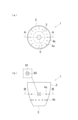
- FIG. 2 is (a) a plan view and (b) a side view of the flower pot according to the first embodiment.
- FIG. 3 is (a) a sectional view taken along the line BB and (b) a sectional view taken along the line AA of the flower pot according to the first embodiment.
- FIG. 4 is a schematic enlarged cross-sectional view taken along the line AA of the main part C showing the inclined state of the ventilation holes in the flower pot according to the first embodiment.
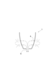
- FIG. 5 is a schematic diagram showing the effect of the ventilation section in the flower pot according to the first embodiment.
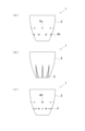
- FIG. 6 is a side view of a flowerpot according to a modified example, in which (a) a side view of a flowerpot according to a second embodiment, (b) a side view of a flowerpot according to a third embodiment, and (c) a side view of a flowerpot according to a fourth embodiment. It is a side view of a flowerpot.
- FIG. 7 is a schematic enlarged cross-sectional view taken along the line AA of the main part C showing the shape of the ventilation holes in the flower pot according to the fifth embodiment.
- FIG. 8 is (a) a side view and (b) a sectional view taken along the line AA of a flower pot according to the sixth embodiment.
- FIG. 7 is a schematic enlarged cross-sectional view taken along the line AA of the main part C showing the shape of the ventilation holes in the flower pot according to the fifth embodiment.
- FIG. 8 is (a) a side view and (b) a sectional view taken along the line AA of a flower pot according to
- FIG. 9 is a schematic diagram showing variations of recesses in the flowerpot according to Embodiment 6.
- FIG. 10 is a sectional view of a flower pot according to Embodiment 7.
- FIG. 11 is (a) a cross-sectional view of a modified example of the flower pot according to the seventh embodiment, and (b) a cross-sectional view of another modified example of the flower pot according to the seventh embodiment.
- FIG. 12 is (a) a cross-sectional view of a flower pot according to comparative form 1, and (b) a cross-sectional view of a flower pot according to comparative form 2.
- the flower pot of the present disclosure includes: Equipped with a ventilation section on the side,
- the ventilation section has a first opening that opens toward the outside of the flower pot, and a second opening that opens toward the inside of the flower pot,
- the opening area of the first opening is larger than the opening area of the second opening.
- the ventilation section can be at least one of a ventilation hole penetrating the side surface and a slit formed in the side surface.
- the ventilation hole may include a tapered portion that narrows from the first opening toward the second opening.
- the ventilation hole may further include a cylindrical portion having the same diameter as the second opening.
- the slit may be formed in a triangular shape that widens toward the bottom of the flowerpot.
- the slit may be formed such that the slit width narrows from the outside to the inside of the side surface.
- the flower pot of the present disclosure may include a recess on the outer surface of the side surface, and the recess may be formed from the edge of the first opening toward the bottom of the flower pot.
- the side surface bulges outward, and the inner surface of the side surface is formed in a tapered shape that narrows from the upper opening of the flowerpot toward the bottom of the flowerpot. I can do it.
- the flower pot 1 of the first embodiment has a side surface 2 and a bottom surface 3.
- the side surface portion 2 is provided so as to stand upward from the outer peripheral edge of the bottom surface portion 3.
- the bottom part 3 is provided with a drainage hole 6 for draining water that has descended to the bottom part 3.
- the side surface portion 2 includes a ventilation portion.
- the ventilation section connects the space outside the flowerpot 1 and the space inside the flowerpot 1 in a ventilable manner.
- the ventilation portion can be provided, for example, so as to penetrate the side surface portion 2.
- the ventilation section is specifically composed of ventilation holes 4 (4a, 4b) penetrating the side surface section 2.
- FIGS. 1 to 5 show an example in which a plurality of ventilation holes 4 (4a, 4b) are provided in the circumferential direction of the side surface portion 2.
- the plurality of ventilation holes 4 can be formed in the circumferential direction of the side surface portion 2 at a plurality of height positions having different heights from the bottom surface portion 3 when the bottom surface portion 3 is set as a reference height position. More specifically, in FIGS. 1 to 5, the plurality of ventilation holes 4 are arranged in the side surface 2 at a predetermined height position from the bottom surface 3 when the bottom surface 3 is set at a reference height position.
- the number of ventilation holes 4 in the circumferential direction of the side surface part 2 is It is possible to adopt a configuration in which the number increases toward the section 3.
- the number of second ventilation holes 4b arranged in the circumferential direction of the side surface 2 at a position closer to the bottom surface 3 than the first ventilation holes 4a is larger than that of the second ventilation holes 4b.
- An example is shown in which the number of first ventilation holes 4a is greater than the number of first ventilation holes 4a arranged in the circumferential direction of the side surface portion 2 at a position far from the bottom surface portion 3. According to these configurations, the number of ventilation holes 4 closer to the bottom surface part 3 is greater than the number of ventilation holes 4 farther from the bottom surface part 3, so that the closer to the bottom surface part 3, the more the ventilation can be improved.
- the ventilation hole 4 as a ventilation section has a first opening 41 that opens toward the outside of the flower pot 1 and a second opening 42 that opens toward the inside of the flower pot 1.
- the ventilation hole 4 as a ventilation section has a first opening 41 that opens on the outer surface of the side surface 2 and a second opening 42 that opens on the inner surface of the side surface 2. can.
- the opening area S1 of the first opening 41 is larger than the opening area S2 of the second opening 42.
- the flower pot 1 of Embodiment 1 includes a ventilation hole 4 as a ventilation portion in the side surface 2, and the opening area of the first opening 41 of the ventilation hole 4 is larger than the opening area of the second opening 42 of the ventilation hole 4. Because of this, air from outside the flower pot 1 can be efficiently taken into the flower pot 1.
- the ventilation hole 4 may include a tapered portion 43 that narrows from the first opening 41 toward the second opening 42 . According to this configuration, as shown in FIG. 5, the air outside the flower pot 1 can be collected to strengthen the airflow, and the air can be efficiently sent into the flower pot 1. The introduced air absorbs moisture in the soil inside the flowerpot 1 and is discharged to the outside of the flowerpot 1 through the drainage holes 6 and the like.
- the ventilation hole 4 may further include a cylindrical portion 44 having the same diameter as the second opening 42.
- the airflow strengthened by the tapered portion 43 can be more efficiently sent into the flowerpot 1 through the cylindrical portion 44.
- the tapered portion 43 is provided on the first opening 41 side
- the cylindrical portion 44 is provided on the second opening 42 side.
- the tapered end of the tapered portion 43 communicates with the end of the cylindrical portion 44 on the first opening 41 side.
- FIGS. 2 to 5 an example is shown in which the ventilation hole 4 is formed in a funnel shape as a whole in a cross-sectional view along the thickness direction of the side surface portion 2.
- the central axis 45 of the ventilation hole 4 can be formed to rise toward the inside of the flowerpot 1, as illustrated in FIG. 4(a). According to this configuration, for example, when the flowerpot 1 is installed near the ceiling of a room (at a high position), it becomes easier to take in the rising air flow. Moreover, the center axis 45 of the ventilation hole 4 can be formed horizontally, as illustrated in FIG. 4(b). According to this configuration, for example, when the flower pot 1 is installed near the middle between the ceiling and the floor (middle position), it becomes easier to take in horizontal air flow. Moreover, the central axis 45 of the ventilation hole 4 can be formed so as to descend toward the inside of the flowerpot 1, as illustrated in FIG. 4(c). According to this configuration, for example, when the flower pot 1 is installed near the floor (at a low position), it becomes easier to take in the downward flow of air.
- Embodiment 2 The flowerpot of Embodiment 2 will be described using FIG. 6(a). Note that among the symbols used in the second embodiment and subsequent embodiments, the same symbols as those used in the previously described embodiments represent the same components as those in the previously described embodiments, unless otherwise specified.
- the flower pot 1 of Embodiment 1 described above is an example in which the ventilation section is configured by a plurality of ventilation holes 4 having the same size.
- the flowerpot 1 according to the second embodiment is an example in which the ventilation section is formed by a plurality of ventilation holes 4 having different sizes, as illustrated in FIG. 6(a). In this way, the plurality of ventilation holes 4 do not necessarily have to have the same size, and even if they have different sizes, air from outside the flowerpot 1 can be efficiently taken into the inside of the flowerpot 1.
- the ventilation in the circumferential direction of the side surface part 2 is The size of the hole 4 may be configured to become larger toward the bottom portion 3.
- the size of the second ventilation hole 4b which is arranged in the circumferential direction of the side surface part 2 at a position closer to the bottom surface part 3 than the first ventilation hole 4a, is larger than that of the second ventilation hole 4b.
- the size of the first ventilation hole 4a is larger than that of the first ventilation hole 4a arranged in the circumferential direction of the side surface portion 2 at a position farther from the bottom surface portion 3 than the first ventilation hole 4a.
- the size of the ventilation holes 4 closer to the bottom part 3 is formed larger than the size of the ventilation holes 4 farther from the bottom part 4, so that the closer to the bottom part 3, the more the ventilation improves. be able to.
- the second ventilation hole 4b As a method of making the size of the second ventilation hole 4b larger than the size of the first ventilation hole 4a, for example, in a cross-sectional view along the thickness direction of the side surface part 2, the second ventilation hole 4b This can be realized by, for example, making the cross-sectional area or outer shape of the first ventilation hole 4a larger than the cross-sectional area or outer shape of the first ventilation hole 4a.
- Embodiment 3 The flower pot of Embodiment 3 will be explained using FIG. 6(b).
- the flowerpot 1 of the first and second embodiments described above is an example in which the ventilation portion is formed by the ventilation hole 4 penetrating the side surface portion 2.
- the flowerpot 1 of Embodiment 3 is an example in which the ventilation portion is formed by the slit 5 formed in the side surface portion 2, as illustrated in FIG. 6(b).
- FIG. 6(b) shows an example in which a plurality of slits 5 are formed in the circumferential direction of the side surface portion 2.
- the slit 5 as a ventilation section has a first opening that opens toward the outside of the flower pot 1 and a second opening that opens toward the inside of the flower pot 1. That is, it can be said that the slit 5 as a ventilation section has a first opening that opens on the outer surface of the side surface 2 and a second opening that opens on the inner surface of the side surface 2. The opening area of the first opening is larger than the opening area of the second opening.
- the form of the ventilation section is not necessarily limited to the ventilation hole 4, but even if it is a slit 5, air from outside the flowerpot 1 can be efficiently taken into the inside of the flowerpot 1.
- the slit 5 may be formed in a triangular shape that widens toward the bottom surface 3 of the flower pot 1. Note that the shape of the slit 5 is determined by looking from the outside of the flowerpot 1. According to the above configuration, the air permeability can be improved toward the bottom portion 3.
- the slit 5 may be formed such that the slit width narrows from the outside to the inside of the side surface portion 2. According to this configuration, the air outside the flower pot 1 can be collected to strengthen the airflow, and the air can be efficiently sent into the flower pot 1.
- Embodiment 4 The flower pot of Embodiment 4 will be explained using FIG. 6(c).
- the flowerpot 1 of the fourth embodiment a portion of the plurality of ventilation holes 4 is closed with kintsugi 46, and the ventilation holes 4 are used as a decoration of the flowerpot 1. That is, it can be said that the flower pot 1 of Embodiment 4 has the kintsugi 46 that closes some of the plurality of ventilation holes 4 . According to the above configuration, the design of the flowerpot 1 itself can be improved while ensuring ventilation suitable for the installation location of the flowerpot 1.
- Embodiment 5 The flower pot of Embodiment 5 will be described using FIG. 7.
- the flowerpot 1 of the first and second embodiments described above is an example in which the ventilation hole 4 as a ventilation section is configured so that there is no curved part between the first opening 41 and the second opening 42. It is.
- the flowerpot 1 of the fifth embodiment is an example in which the ventilation hole 4 has a curved part between the first opening 41 and the second opening 42, as illustrated in FIG. It is.
- FIGS. 7(a) and 7(b) show an example in which the ventilation hole 4 as a ventilation portion is provided in a bent state with a bent portion. Further, FIGS. 7(c) and 7(d) show an example in which the ventilation hole 4 serving as a ventilation portion does not have a clear bent portion and is provided in a curved state. According to such a configuration, air taken in from outside of the flowerpot 1 can be guided in a desired direction inside the flowerpot 1.
- the airflow holes 4 as shown in FIGS. After intake, the air flow can be directed horizontally.
- the ventilation holes 4 as shown in FIGS. After capturing the flow, the air flow can be directed horizontally.
- the ventilation can be finely adjusted depending on the type of plant to be cultivated and the installation location.
- the opening area S1 of the first opening 41 that opens on the outside of the flower pot 1 and the opening area S2 of the second opening 42 that opens on the inside of the flower pot 1 are equal.
- the opening area S1 of the first opening 41 is larger than the opening area S2 of the second opening 42 in the fifth embodiment as well.
- Embodiment 6 The flower pot of Embodiment 6 will be described using FIGS. 8 and 9.
- the flowerpot 1 of the sixth embodiment includes a recess 7 on the outer surface of the side surface 2.
- the recess 7 can also be said to be a groove formed in a predetermined shape on the outer surface of the side surface 2 .
- the recess 7 is formed from the edge of the first opening 41 toward the bottom 3 of the flower pot 1.
- the recess 7 extends from the edge of the first opening 41 to the lower end of the side surface 2, or extends from the edge of a predetermined first opening 41 to the bottom surface of the first opening 41.
- An example is shown in which it extends to the edge of another predetermined first opening 41 on the side (lower side) of the section 3 .
- the flowerpot 1 of the sixth embodiment water components and soil components flowing out from the first opening 41 are guided to the recess 7, and calcification marks and pigmentation occur according to the shape of the recess 7. Therefore, according to the flowerpot 1 of the sixth embodiment, the calcification marks and pigmentation can be used as the design of the flowerpot 1, and the appearance of the flowerpot 1 can be prevented from deteriorating.
- FIG. 8 shows an example in which the recess 7 is formed in a triangular or rhombic shape expanding from the first opening 41 when viewed from the outside of the side surface 2. It is preferable that the recessed part 7 includes one formed so as to extend to the lower end of the side surface part 2 so as not to overflow water components and soil components.
- the ventilation hole 4b is provided below the ventilation hole 4a, the recess 7 whose base end is the first opening 41 of the ventilation hole 4a is formed at the upper edge of the first opening 41 of the ventilation hole 4b. It is preferable to connect with the section.
- the recess 7 can be formed in various shapes. Specifically, the recess 7 has a shape extending in a band shape from the first opening 41 (FIG. 9(a)), a shape extending in a curved band shape from the first opening 41 (FIG. 9(b)), and a shape extending in a band shape from the first opening 41 (FIG. 9(b)). It can be formed into a triangular shape expanding from the opening 41 (FIG. 9(c)), an inverted triangular shape narrowing from the first opening 41 (FIG. 9(d)), or the like. Furthermore, one flowerpot 1 can be configured to include recesses 7 of a plurality of different shapes, or can be configured to include recesses 7 of a plurality of different lengths, widths, and depths.
- Embodiment 7 The flower pot of Embodiment 7 will be explained using FIGS. 10 to 12.
- the side surface 2 swells outward, and the inner surface of the side surface 2 extends from the top opening of the flowerpot 1 to the bottom surface 3 of the flowerpot 1. It is formed in a tapered shape that narrows toward.
- the side surface portion 910 bulges outward, but the inner surface of the side surface portion 91 is also formed to bulge outward.
- the inner surface of the side surface portion 92 is usually formed along the outer surface of the side surface portion 92. This is because, for example, in a molding method such as potter's wheel molding, the wall thickness of the side surface portion 910 is generally constant.
- the flowerpot 91 of Comparative Embodiment 1 has a problem in that when the plant is replanted, the soil covered with the plant's roots gets caught on the inner surface of the side surface 91, damaging the plant's roots.
- the soil with the roots of the plant is not caught on the inner surface of the side part 2, so that the plant can be replanted without damaging the roots of the plant. It can be performed.
- the wall thickness of the side surface 2 is between the outer surface of the side surface 2 that bulges outward and the tapered inner surface that narrows toward the bottom surface 3, and the flower pot 1 increases, and the stability of the flower pot 1 improves. Therefore, according to the flowerpot 1 of Embodiment 7, even when growing plants that are relatively heavy in the pot, such as tuberous plants and succulents, the plants can be grown while suppressing the fall of the flowerpot 1. be able to.
- FIG. 10 shows an example in which the entire side surface portion 2 bulges outward
- a portion of the side surface portion 2 does not bulge outward.
- the side surface portion 2 may bulge outward in a stepped manner.
- the protrusion 921 protrudes from the outer surface of the side surface 920 having a certain wall thickness. It cannot be said that it is bulging outward. Whether or not the side surface portion 2 bulges outward can be determined from the cross section of the flowerpot 1 along the vertical direction.
- the present disclosure is not limited to the embodiments described above, and the shapes and configurations of each part can be changed as appropriate without departing from the gist of the present disclosure. Furthermore, the configurations shown in the above embodiments can be combined arbitrarily.
Landscapes
- Life Sciences & Earth Sciences (AREA)
- Environmental Sciences (AREA)
- Cultivation Receptacles Or Flower-Pots, Or Pots For Seedlings (AREA)
Abstract
Priority Applications (3)
| Application Number | Priority Date | Filing Date | Title |
|---|---|---|---|
| US18/705,037 US20240415069A1 (en) | 2022-07-13 | 2023-07-06 | Plant pot |
| JP2024506576A JP7503879B2 (ja) | 2022-07-13 | 2023-07-06 | 植木鉢 |
| EP23839556.0A EP4410092A4 (fr) | 2022-07-13 | 2023-07-06 | Pot de fleur |
Applications Claiming Priority (2)
| Application Number | Priority Date | Filing Date | Title |
|---|---|---|---|
| JP2022-112319 | 2022-07-13 | ||
| JP2022112319 | 2022-07-13 |
Publications (1)
| Publication Number | Publication Date |
|---|---|
| WO2024014384A1 true WO2024014384A1 (fr) | 2024-01-18 |
Family
ID=89536701
Family Applications (1)
| Application Number | Title | Priority Date | Filing Date |
|---|---|---|---|
| PCT/JP2023/025076 Ceased WO2024014384A1 (fr) | 2022-07-13 | 2023-07-06 | Pot de fleur |
Country Status (4)
| Country | Link |
|---|---|
| US (1) | US20240415069A1 (fr) |
| EP (1) | EP4410092A4 (fr) |
| JP (1) | JP7503879B2 (fr) |
| WO (1) | WO2024014384A1 (fr) |
Citations (6)
| Publication number | Priority date | Publication date | Assignee | Title |
|---|---|---|---|---|
| JPS53100463U (fr) * | 1977-01-18 | 1978-08-14 | ||
| JPS55131327A (en) * | 1979-03-30 | 1980-10-13 | Guruubaa Buruno | Cultivating method and container for plant |
| JPS61100963U (fr) | 1984-12-06 | 1986-06-27 | ||
| JP2017521996A (ja) * | 2014-06-18 | 2017-08-10 | アウアジア・アグロテック・スンディリアン・ブルハド | 植物栽培容器 |
| JP3217627U (ja) * | 2018-04-23 | 2018-08-23 | 成樹 山下 | 樹脂ポット |
| JP2022112319A (ja) | 2021-01-21 | 2022-08-02 | 幸 常田 | 台風発生抑制装置 |
Family Cites Families (4)
| Publication number | Priority date | Publication date | Assignee | Title |
|---|---|---|---|---|
| US4173097A (en) * | 1977-09-14 | 1979-11-06 | Staby George L | Container with raised indentations for aeration and drainage |
| US20190029195A1 (en) | 2017-07-31 | 2019-01-31 | Li-Yuan LI | Flowerpot with Water Conservation Arrangement |
| USD892673S1 (en) * | 2018-07-11 | 2020-08-11 | International Plant Propagation Technology Ltd | Single cell of a plant-growing tray |
| USD930500S1 (en) * | 2019-05-07 | 2021-09-14 | International Plant Propagation Technology Ltd | Plant-growing container |
-
2023
- 2023-07-06 US US18/705,037 patent/US20240415069A1/en active Pending
- 2023-07-06 JP JP2024506576A patent/JP7503879B2/ja active Active
- 2023-07-06 EP EP23839556.0A patent/EP4410092A4/fr not_active Withdrawn
- 2023-07-06 WO PCT/JP2023/025076 patent/WO2024014384A1/fr not_active Ceased
Patent Citations (6)
| Publication number | Priority date | Publication date | Assignee | Title |
|---|---|---|---|---|
| JPS53100463U (fr) * | 1977-01-18 | 1978-08-14 | ||
| JPS55131327A (en) * | 1979-03-30 | 1980-10-13 | Guruubaa Buruno | Cultivating method and container for plant |
| JPS61100963U (fr) | 1984-12-06 | 1986-06-27 | ||
| JP2017521996A (ja) * | 2014-06-18 | 2017-08-10 | アウアジア・アグロテック・スンディリアン・ブルハド | 植物栽培容器 |
| JP3217627U (ja) * | 2018-04-23 | 2018-08-23 | 成樹 山下 | 樹脂ポット |
| JP2022112319A (ja) | 2021-01-21 | 2022-08-02 | 幸 常田 | 台風発生抑制装置 |
Non-Patent Citations (1)
| Title |
|---|
| See also references of EP4410092A4 |
Also Published As
| Publication number | Publication date |
|---|---|
| JP7503879B2 (ja) | 2024-06-21 |
| EP4410092A4 (fr) | 2025-06-11 |
| EP4410092A1 (fr) | 2024-08-07 |
| JPWO2024014384A1 (fr) | 2024-01-18 |
| US20240415069A1 (en) | 2024-12-19 |
Similar Documents
| Publication | Publication Date | Title |
|---|---|---|
| US20080256855A1 (en) | Landscape device | |
| CN204707554U (zh) | 保水透气栽培盆 | |
| US5044119A (en) | Flowerpot bowl | |
| WO2024014384A1 (fr) | Pot de fleur | |
| CN202340511U (zh) | 花盆 | |
| JP2000201544A (ja) | 育苗用栽培容器 | |
| CN217608529U (zh) | 一种种植盆 | |
| KR200459222Y1 (ko) | 화분 | |
| CN216567284U (zh) | 一种透气控根塔式花盆 | |
| KR200166753Y1 (ko) | 육묘용재배용기 | |
| US20160235016A1 (en) | Soft plant pot | |
| JP3219872U (ja) | 植木鉢 | |
| CN203761936U (zh) | 栽培软盆 | |
| KR20250107502A (ko) | 난 식재용 이중 화분 | |
| JP3187766U (ja) | 苺の花托形状矯正具 | |
| KR200359219Y1 (ko) | 활엽수용 양묘 포트 | |
| JP3035925U (ja) | 植木鉢 | |
| JP3160519U (ja) | 周形植木鉢 | |
| JP3108080U (ja) | 周りに凹凸がある植木鉢 | |
| JP2008092880A (ja) | 育苗ポット | |
| JP3120812U (ja) | 植栽容器 | |
| KR200469255Y1 (ko) | 뿌리돌기 방지 및 통기ㆍ배수 기능을 갖는 화분 | |
| RU36163U1 (ru) | Горшок для цветов с поддонником | |
| JP3125387U (ja) | 浅鉢を利用した蘭の鉢植え及び栽培方法 | |
| KR200188632Y1 (ko) | 콩나물 재배용기 |
Legal Events
| Date | Code | Title | Description |
|---|---|---|---|
| WWE | Wipo information: entry into national phase |
Ref document number: 2024506576 Country of ref document: JP |
|
| 121 | Ep: the epo has been informed by wipo that ep was designated in this application |
Ref document number: 23839556 Country of ref document: EP Kind code of ref document: A1 |
|
| WWE | Wipo information: entry into national phase |
Ref document number: 18705037 Country of ref document: US |
|
| ENP | Entry into the national phase |
Ref document number: 2023839556 Country of ref document: EP Effective date: 20240502 |
|
| NENP | Non-entry into the national phase |
Ref country code: DE |
|
| WWW | Wipo information: withdrawn in national office |
Ref document number: 2023839556 Country of ref document: EP |