WO2024018651A1 - Ventilateur de soufflage, et machine à laver/sécher et machine à sécher comportant celui-ci - Google Patents
Ventilateur de soufflage, et machine à laver/sécher et machine à sécher comportant celui-ci Download PDFInfo
- Publication number
- WO2024018651A1 WO2024018651A1 PCT/JP2023/000957 JP2023000957W WO2024018651A1 WO 2024018651 A1 WO2024018651 A1 WO 2024018651A1 JP 2023000957 W JP2023000957 W JP 2023000957W WO 2024018651 A1 WO2024018651 A1 WO 2024018651A1
- Authority
- WO
- WIPO (PCT)
- Prior art keywords
- flow path
- blower
- heater
- scroll
- centrifugal impeller
- Prior art date
- Legal status (The legal status is an assumption and is not a legal conclusion. Google has not performed a legal analysis and makes no representation as to the accuracy of the status listed.)
- Ceased
Links
Images



Classifications
-
- D—TEXTILES; PAPER
- D06—TREATMENT OF TEXTILES OR THE LIKE; LAUNDERING; FLEXIBLE MATERIALS NOT OTHERWISE PROVIDED FOR
- D06F—LAUNDERING, DRYING, IRONING, PRESSING OR FOLDING TEXTILE ARTICLES
- D06F25/00—Washing machines with receptacles, e.g. perforated, having a rotary movement, e.g. oscillatory movement, the receptacle serving both for washing and for centrifugally separating water from the laundry and having further drying means, e.g. using hot air
-
- D—TEXTILES; PAPER
- D06—TREATMENT OF TEXTILES OR THE LIKE; LAUNDERING; FLEXIBLE MATERIALS NOT OTHERWISE PROVIDED FOR
- D06F—LAUNDERING, DRYING, IRONING, PRESSING OR FOLDING TEXTILE ARTICLES
- D06F58/00—Domestic laundry dryers
- D06F58/20—General details of domestic laundry dryers
Definitions
- the present disclosure relates to a blower, and a washer/dryer and dryer equipped with the same.
- a blower and heating device When drying clothes using a washer/dryer, which can perform the continuous process from washing to drying, a blower and heating device create high-temperature, low-humidity air, which is blown into the washing tub to raise the temperature of the clothes and remove moisture from them. This is done by evaporating the water and discharging the evaporated water outside the machine. At this time, in order to increase the heating efficiency in the heating means, it is desirable that the flow generated by the blower be applied to the heating means at a uniform flow rate.
- Patent Document 1 discloses that in a hot air unit 22 built into a washer/dryer, in order to uniformly distribute the flow rate of air discharged from a discharge port 208 toward a heating heater 24 by rotation of a blower fan 202, a rear side On the end 209 side, there is a protrusion 211 that protrudes toward the nose 210 so as to narrow the discharge port 208 , and is located between the rear end 209 and one end of the heater 24 . It is disclosed that the opposing centers have a raised shape.
- the hot air unit described in Patent Document 1 has a configuration in which a raised portion is provided toward the nose portion (tongue portion) of the blower to make the flow uniform.
- a raised portion is provided toward the nose portion, the rising portion of the raised portion exists within the scroll, and the flow path cross-sectional area near the impeller where the flow velocity is high is becomes smaller. For this reason, friction loss between the fluid and the wall surface increases, and there is a concern that the blower efficiency will decrease.
- the present disclosure aims to make the flow of air to the heater uniform in a blower equipped with a centrifugal impeller and a heater, and to suppress an increase in flow path resistance.
- the blower of the present disclosure includes an electric motor, a centrifugal impeller provided on the rotating shaft of the electric motor, a scroll flow path provided around the centrifugal impeller, and an enlarged flow path provided at the downstream end of the scroll flow path. and a heater provided at the downstream end of the expanded flow path, and the expanded flow path is provided with a convex portion from a radially outer wall surface toward a radially inner wall surface when viewed from the centrifugal impeller. .
- a blower including a centrifugal impeller and a heater, it is possible to make the flow of air to the heater uniform and to suppress an increase in flow path resistance.
- FIG. 2 is an exploded perspective view of the blower according to the embodiment, viewed from the fan cover side.
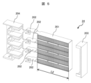
- FIG. 2 is an exploded perspective view of the blower according to the embodiment, viewed from the electric motor side. It is an exploded perspective view showing an electric heater of an example.
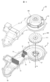
- FIG. 3 is a plan view showing a state in which a fan cover is removed from the blower of the embodiment.
- FIG. 1 is a longitudinal sectional view showing a washing machine equipped with an air blower according to an embodiment. Note that although a vertical washer/dryer will be described as an example below, the present invention can also be applied to a drum-type washer/dryer and a drum-type dryer in which a laundry loading/unloading port is formed on the front side.
- the washing machine S includes an outer frame 1 that is a housing, an outer tank 2 that stores washing water, a rotating tank 3, a drive motor 10, a blower 22, and the like.
- the outer tank 2 is built into the outer frame 1 and supported by the outer frame 1 in a vibration-proof manner.
- the rotating tub 3 is a washing tub and a dehydrating tub that accommodates laundry such as clothes to be washed and dried, and is provided inside the outer tub 2. Further, the rotating tank 3 is rotatably supported within the outer tank 2.
- a stirring blade 4 for stirring and washing the laundry is rotatably provided.
- the agitating blade 4 repeats forward and reverse rotation during washing operation and drying operation. Further, the stirring blade 4 rotates at high speed together with the rotating tank 3 during dehydration operation. Most of the moisture from the laundry in the rotating tub 3 is removed by dehydration.
- an outer lid 5 is provided on the upper part of the outer frame 1.
- This outer lid 5 is provided on a top cover 6 provided on the upper part of the outer frame 1 so as to be openable and closable.
- An inner lid 34 is provided on the upper part of the outer tank 2 so as to be openable and closable.
- the washing machine S is equipped with a drying mechanism.
- This drying mechanism performs circulation and dehumidification of drying air for drying the laundry in the rotary tub 3.
- the drying mechanism mainly includes a drying air circulation path 9 and a blower 22.
- the drying air circulation path 9 includes a bottom circulation path 20 connected to the bottom of the outer tank 2 so as to communicate therewith, and a dehumidification vertical path 21 extending upward from the bottom circulation path 20.
- the suction side of the blower 22 is connected to the upper side of the dehumidifying vertical passage 21.
- a discharge side of the blower 22 is connected to communicate with a return connection circulation path 25 .
- a drying filter 45 is arranged between the blower 22 and the vertical dehumidifying passage 21 to prevent foreign matter from flowing into the blower 22.
- the blower 22 has a built-in electric heater.
- the return connection circulation path 25 has an upper bellows hose 23 and is connected to communicate with the upper part of the outer tank 2 via the upper bellows hose 23.
- the bottom circulation path 20 also has a lower bellows hose 26, and is connected to the bottom of the outer tank 2 via the lower bellows hose 26 so as to communicate therewith.
- the lower bellows hose 26 is connected to the bottom drop part 31 of the outer tank 2. This bottom drop portion 31 communicates with a washing water drainage channel 42 and a washing water circulation channel 43 via a lower communication pipe 41.
- a drain valve 44 is provided in the washing water drain channel 42.
- a foreign matter removal trap 32 is provided in the washing water circulation channel 43.
- the drying air sent from the blower 22 passes through the return connection circulation path 25, the outer tank 2, the bottom depression 31, the lower bellows hose 26, and the drying air circulation path 9 in this order. , and is configured to return to the blower 22.
- the drain valve 44 is closed during washing and drying operations. Further, the drain valve 44 opens when washing water is drained, and drains the washing water accumulated in the outer tub 2 from the washing water drain path 42 to the outside of the washing machine S (outside the machine).
- the centrifugal impeller 300 (see FIG. 2) of the blower 22 rotates, so that drying air flows through the rotating tub 3 and dries the laundry in the rotating tub 3. Furthermore, the drying air in which moisture has been condensed in the dehumidifying area is reheated by the electric heater 24 (see FIG. 3) of the blower 22 and flows through the rotating tub 3, thereby further evaporating moisture from the laundry. The laundry is dried by repeating this water removal with circulation of drying air.
- FIG. 2 is an external perspective view showing the blower of the embodiment.
- the blower 22 includes a fan cover 51, a fan casing 52, an electric motor 100, and a centrifugal impeller 300.
- the fan cover 51 and the fan casing 52 constitute a casing 500.
- the blower 22 is installed within the outer frame 1 (see FIG. 1) of the washing machine S (see FIG. 1), for example, with the fan cover 51 of the blower 22 facing substantially downward.
- the method of attaching the blower 22 is not limited to this.
- a suction port 57 and a discharge port 58 are formed in the fan cover 51.
- the suction port 57 is connected to the dehumidifying vertical passage 21 (see FIG. 1) via the dry filter 45 (see FIG. 1).
- the outlet 58 is connected to the return connection circuit 25 (see FIG. 1) of the drying air circuit.
- FIG. 3 is an exploded perspective view of the blower of this embodiment, viewed from the fan cover side.
- FIG. 4 is an exploded perspective view of the blower of this embodiment, viewed from the motor side.
- the fan cover 51 has an elongated shape in one direction, with a suction port 57 formed in one longitudinal direction, and an exhaust port 58 formed in the other longitudinal direction.
- the suction port 57 is a circular through hole, and faces the center of the suction opening 302 (suction portion) of the centrifugal impeller 300.
- the discharge port 58 is a circular through hole and is located downstream of the electric heater 24. Further, the diameter of the discharge port 58 is larger than the diameter of the suction port 57. Further, the suction port 57 and the discharge port 58 are arranged in substantially the same direction.
- screw fixing portions 91 that are screwed to the fan casing 52 are formed at a plurality of locations on the peripheral edge of the fan cover 51.
- the fan casing 52 has a shape corresponding to the fan cover 51. When the fan casing 52 and the fan cover 51 are combined, a space is formed between the fan cover 51 and the fan casing 52 in which the centrifugal impeller 300 and the electric heater 24 are arranged.
- the fan casing 52 is formed with a shaft insertion hole 80 into which the rotating shaft 101 of the electric motor 100 is inserted. Further, a screw insertion portion 92 into which a screw (not shown) is inserted is formed on the outer peripheral edge of the fan casing 52 at a position corresponding to the screw fixing portion 91 of the fan cover 51.
- the fan casing 52 and the fan cover 51 form a scroll passage 70 around the outer periphery (outside in the radial direction) of the centrifugal impeller 300.
- the scroll flow path 70 is configured such that the flow path width on the tongue portion 71 side is narrow, and the flow path width gradually increases from the tongue portion 71 in a clockwise direction.
- the tongue portion 71 is the starting point of the scroll flow path 70.
- the outlet of the scroll flow path 70 is a scroll discharge port 72.
- an enlarged flow path 73 is provided between the scroll discharge port 72 and the electric heater 24.
- the enlarged channel 73 is provided such that the enlarged channel outlet 74 has a larger cross-sectional area than the inlet (scroll discharge port 72) of the enlarged channel 73.
- the enlarged flow path 73 has a convex portion 75 that protrudes from the radially outer wall surface 76 toward the radially inner wall surface 77 when viewed from the centrifugal impeller 300 . If a surface passing through the apex A of the convex portion 75 and parallel to the enlarged channel outlet 74 is defined as a convex channel cross section 78 , the area of the convex channel cross section 78 is smaller than that of the scroll discharge port 72 . Note that the scroll discharge port 72, the enlarged channel outlet 74, and the convex channel cross section 78 are planes parallel to the front surface (considered as a plane) of the electric heater 24.
- the normal line of the scroll discharge port 72 (channel cross section) does not intersect with the rotation axis 101 (rotation center axis) of the centrifugal impeller 300. Therefore, it can be said that the radially outer wall surface 76 is located at a position radially farther away from the rotating shaft 101 than the radially inner wall surface 77 . Therefore, in this specification, the terms “radially outer” and “radially inner” are used.
- the flow path length L1 from the apex A of the convex portion 75 to the enlarged flow path outlet 74 is set to be larger than the width L2 of the heating portion 201 of the electric heater 24.
- the electric motor 100 has a rotating shaft 101 connected to the centrifugal impeller 300 at its radial center, and is attached to the fan casing 52. Further, the electric motor 100 includes a rotor (rotor) fixed to the rotating shaft 101, a stator (stator) provided around the rotor, and a bearing that rotatably supports the rotating shaft 101. Further, the electric motor 100 has a substantially cylindrical case 102 that accommodates a rotor, a stator, and a bearing.
- the centrifugal impeller 300 is constructed by combining a shroud plate 301, a hub plate 311, and blades 321.
- the shroud plate 301 has a circular suction opening 302 formed in the center in the radial direction.
- the hub plate 311 is formed with a shaft hole (not shown) for fixing the rotating shaft 101.
- the blade 321 is constructed by sandwiching the shroud plate 301 and the hub plate 311 from both sides in the axial direction Ax.
- FIG. 5 is an exploded perspective view showing the electric heater of this example.
- the electric heater 24 includes a large number of fins, a rectangular heating part 201 that is a heat generating part, a terminal part 202 that connects the heating part 201 to an electric circuit, and a heating part 202 that fixes the heating part 201. It is composed of a part fixing tool 203 and a terminal part fixing tool 204 that fixes the terminal part 202.
- FIG. 6 is a plan view showing the blower of this embodiment with the fan cover removed.
- the flow exiting the centrifugal impeller 300 flows into the scroll flow path 70 and then into the enlarged flow path 73.
- the flow velocity on the radially outer wall surface 76 side becomes higher than on the radially inner wall surface 77 side due to the influence of centrifugal force, resulting in a biased flow.
- the enlarged flow path 73 does not have the convex portion 75, the flow reaches the electric heater 24 with the same flow velocity distribution, and a uniform flow cannot be provided to the electric heater 24.
- the scroll discharge port 72 is defined as a plane that passes through the tongue portion 71 and is parallel to the front surface of the electric heater 24. In this figure, this corresponds to the position of the rising portion (upstream end) of the convex portion 75. However, the rising portion of the convex portion 75 is not limited to this position, and may be arranged downstream from this position.
- the flow path upstream of the scroll discharge port 72 is included in the scroll flow path 70.
- the scroll flow path 70 is intentionally provided with neither convex portions nor concave portions. Therefore, the flow path wall of the scroll flow path 70 has a shape close to the theoretically appropriate shape for the scroll flow path 70.
- the convex portion 75 is provided so that at least the flow path length L1 is larger than the width L2 of the heating portion of the electric heater 24. Therefore, the flow changed by the convex portion 75 can be sufficiently diffused before reaching the electric heater 24, and a more uniform flow can be provided to the electric heater 24.
- the convex portion 75 is provided not within the scroll flow path 70 but within the enlarged flow path 73 downstream thereof.
- the convex portion 75 can be provided without narrowing the flow passage cross-sectional area around the centrifugal impeller 300 where the flow velocity is high, and the friction loss between the fluid and the wall surface forming the scroll flow passage 70 can be greatly increased. This makes it possible to provide a uniform flow to the electric heater 24.
- the blower 22 of this embodiment includes the electric motor 100, the rotating shaft 101 rotatably provided on the electric motor 100, the centrifugal impeller 300 provided on the rotating shaft 101, and the surroundings of the centrifugal impeller 300.
- the convex portion 75 in the enlarged flow path 73 allows a part of the flow biased toward the outside in the radial direction to be guided toward the inside in the radial direction, making it possible to provide a uniform flow to the electric heater 24.
- the convex portion 75 is provided so that the flow path length L1 is larger than the width L2 of the heating part of the electric heater 24, the flow changed by the convex portion 75 is sufficiently diffused before reaching the electric heater 24.
- the electric heater 24 can provide a uniform flow.
- the convex portion 75 can be provided without narrowing the flow path cross-sectional area around the centrifugal impeller 300 where the flow velocity is high. It is possible to provide a uniform flow to the electric heater 24 without significantly increasing the friction loss between the fluid and the wall surface forming the scroll flow path 70.
- the slope of the curve of the convex portion 75 shown in FIG. 6 is gentler on the downstream side than on the upstream side of the apex A of the convex portion 75.
- blower 22 of this embodiment is provided in the washing machine S. Since the blower 22 can improve the heating efficiency of the electric heater 24 while suppressing performance deterioration, it is possible to reduce the power consumption of the washing machine S.
- the expanded flow path extends from the scroll outlet, which is the downstream end of the scroll flow path, to the front surface of the heating section of the heater, and the scroll outlet is parallel to the front surface of the heating section.
- the length of the flow path from the apex of the convex portion to the front surface of the heating section of the heater is set longer than the width of the heating section of the heater.
- the convex portion is provided so that a perpendicular to the front surface of the heating portion of the heater, which passes through the apex of the convex portion, passes closer to the radially outer wall surface of the enlarged channel than the center of the heating portion.
- the washer/dryer is equipped with the above blower.
- the dryer is equipped with the above blower.
Landscapes
- Engineering & Computer Science (AREA)
- Textile Engineering (AREA)
- Detail Structures Of Washing Machines And Dryers (AREA)
- Main Body Construction Of Washing Machines And Laundry Dryers (AREA)
Abstract
Priority Applications (1)
| Application Number | Priority Date | Filing Date | Title |
|---|---|---|---|
| CN202380041720.XA CN119325530A (zh) | 2022-07-19 | 2023-01-16 | 风机以及包括它的洗涤干燥机和干燥机 |
Applications Claiming Priority (2)
| Application Number | Priority Date | Filing Date | Title |
|---|---|---|---|
| JP2022-114611 | 2022-07-19 | ||
| JP2022114611A JP2024012850A (ja) | 2022-07-19 | 2022-07-19 | 送風機並びにこれを備えた洗濯乾燥機及び乾燥機 |
Publications (1)
| Publication Number | Publication Date |
|---|---|
| WO2024018651A1 true WO2024018651A1 (fr) | 2024-01-25 |
Family
ID=89617554
Family Applications (1)
| Application Number | Title | Priority Date | Filing Date |
|---|---|---|---|
| PCT/JP2023/000957 Ceased WO2024018651A1 (fr) | 2022-07-19 | 2023-01-16 | Ventilateur de soufflage, et machine à laver/sécher et machine à sécher comportant celui-ci |
Country Status (3)
| Country | Link |
|---|---|
| JP (1) | JP2024012850A (fr) |
| CN (1) | CN119325530A (fr) |
| WO (1) | WO2024018651A1 (fr) |
Citations (7)
| Publication number | Priority date | Publication date | Assignee | Title |
|---|---|---|---|---|
| JPS5615491U (fr) * | 1979-07-13 | 1981-02-10 | ||
| JP2000127740A (ja) * | 1998-10-21 | 2000-05-09 | Denso Corp | 遠心送風機 |
| JP2002089494A (ja) * | 2000-09-12 | 2002-03-27 | Mitsubishi Heavy Ind Ltd | 遠心式ファン、及び、空調装置 |
| JP2002130187A (ja) * | 2000-10-23 | 2002-05-09 | Matsushita Seiko Co Ltd | 送風機と浴室乾燥機 |
| JP2014136059A (ja) * | 2013-01-17 | 2014-07-28 | Toshiba Corp | 衣類乾燥機 |
| JP2016221017A (ja) * | 2015-06-01 | 2016-12-28 | 日立アプライアンス株式会社 | 洗濯乾燥機 |
| JP2018086877A (ja) * | 2016-11-28 | 2018-06-07 | 株式会社ヴァレオジャパン | 車両用空調装置 |
-
2022
- 2022-07-19 JP JP2022114611A patent/JP2024012850A/ja active Pending
-
2023
- 2023-01-16 WO PCT/JP2023/000957 patent/WO2024018651A1/fr not_active Ceased
- 2023-01-16 CN CN202380041720.XA patent/CN119325530A/zh active Pending
Patent Citations (7)
| Publication number | Priority date | Publication date | Assignee | Title |
|---|---|---|---|---|
| JPS5615491U (fr) * | 1979-07-13 | 1981-02-10 | ||
| JP2000127740A (ja) * | 1998-10-21 | 2000-05-09 | Denso Corp | 遠心送風機 |
| JP2002089494A (ja) * | 2000-09-12 | 2002-03-27 | Mitsubishi Heavy Ind Ltd | 遠心式ファン、及び、空調装置 |
| JP2002130187A (ja) * | 2000-10-23 | 2002-05-09 | Matsushita Seiko Co Ltd | 送風機と浴室乾燥機 |
| JP2014136059A (ja) * | 2013-01-17 | 2014-07-28 | Toshiba Corp | 衣類乾燥機 |
| JP2016221017A (ja) * | 2015-06-01 | 2016-12-28 | 日立アプライアンス株式会社 | 洗濯乾燥機 |
| JP2018086877A (ja) * | 2016-11-28 | 2018-06-07 | 株式会社ヴァレオジャパン | 車両用空調装置 |
Also Published As
| Publication number | Publication date |
|---|---|
| CN119325530A (zh) | 2025-01-17 |
| JP2024012850A (ja) | 2024-01-31 |
Similar Documents
| Publication | Publication Date | Title |
|---|---|---|
| KR102231079B1 (ko) | 배수 펌프 어셈블리 및 이를 구비하는 의류 건조기 | |
| JP2023085315A (ja) | タンブル乾燥機 | |
| JP5904919B2 (ja) | 洗濯乾燥機 | |
| JP4083662B2 (ja) | ドラム式洗濯乾燥機 | |
| JP4857081B2 (ja) | ドラム式洗濯乾燥機 | |
| JP2008104478A (ja) | 洗濯乾燥機 | |
| JP2024012850A (ja) | 送風機並びにこれを備えた洗濯乾燥機及び乾燥機 | |
| WO2014024354A1 (fr) | Sèche-linge | |
| JP7422172B2 (ja) | 洗濯乾燥機 | |
| JP5886115B2 (ja) | 洗濯乾燥機 | |
| JP7716682B2 (ja) | 衣類乾燥機 | |
| KR102677252B1 (ko) | 팬 어셈블리 및 이를 갖는 세탁기 | |
| CN214458936U (zh) | 衣物处理设备 | |
| JP5599280B2 (ja) | 洗濯乾燥機 | |
| JP2022038702A (ja) | 送風機およびこれを備えた洗濯機 | |
| US3963370A (en) | Laundry machine blower mechanism | |
| JP7365309B2 (ja) | 送風機およびこれを備えた洗濯機 | |
| JP2010065616A (ja) | 遠心式送風機および遠心式送風機を具備した乾燥装置 | |
| JP4566112B2 (ja) | 衣類乾燥機 | |
| JP7365987B2 (ja) | 送風機およびこれを備えた洗濯機 | |
| JP2016221017A (ja) | 洗濯乾燥機 | |
| JP3952915B2 (ja) | 洗濯乾燥機 | |
| CN113446264B (zh) | 风机和洗衣机 | |
| JP7452989B2 (ja) | 送風機および洗濯機 | |
| WO2024014013A1 (fr) | Soufflante et lave-linge/sèche-linge |
Legal Events
| Date | Code | Title | Description |
|---|---|---|---|
| 121 | Ep: the epo has been informed by wipo that ep was designated in this application |
Ref document number: 23842593 Country of ref document: EP Kind code of ref document: A1 |
|
| WWE | Wipo information: entry into national phase |
Ref document number: 202380041720.X Country of ref document: CN |
|
| WWP | Wipo information: published in national office |
Ref document number: 202380041720.X Country of ref document: CN |
|
| NENP | Non-entry into the national phase |
Ref country code: DE |
|
| 122 | Ep: pct application non-entry in european phase |
Ref document number: 23842593 Country of ref document: EP Kind code of ref document: A1 |