WO2024018802A1 - Couche de catalyseur d'électrode, ensemble membrane-électrodes, et pile à combustible à électrolyte polymère - Google Patents
Couche de catalyseur d'électrode, ensemble membrane-électrodes, et pile à combustible à électrolyte polymère Download PDFInfo
- Publication number
- WO2024018802A1 WO2024018802A1 PCT/JP2023/022813 JP2023022813W WO2024018802A1 WO 2024018802 A1 WO2024018802 A1 WO 2024018802A1 JP 2023022813 W JP2023022813 W JP 2023022813W WO 2024018802 A1 WO2024018802 A1 WO 2024018802A1
- Authority
- WO
- WIPO (PCT)
- Prior art keywords
- electrode catalyst
- polymer electrolyte
- catalyst layer
- electrode
- membrane
- Prior art date
- Legal status (The legal status is an assumption and is not a legal conclusion. Google has not performed a legal analysis and makes no representation as to the accuracy of the status listed.)
- Ceased
Links
Images

Classifications
-
- H—ELECTRICITY
- H01—ELECTRIC ELEMENTS
- H01M—PROCESSES OR MEANS, e.g. BATTERIES, FOR THE DIRECT CONVERSION OF CHEMICAL ENERGY INTO ELECTRICAL ENERGY
- H01M4/00—Electrodes
- H01M4/86—Inert electrodes with catalytic activity, e.g. for fuel cells
-
- H—ELECTRICITY
- H01—ELECTRIC ELEMENTS
- H01M—PROCESSES OR MEANS, e.g. BATTERIES, FOR THE DIRECT CONVERSION OF CHEMICAL ENERGY INTO ELECTRICAL ENERGY
- H01M4/00—Electrodes
- H01M4/86—Inert electrodes with catalytic activity, e.g. for fuel cells
- H01M4/96—Carbon-based electrodes
-
- H—ELECTRICITY
- H01—ELECTRIC ELEMENTS
- H01M—PROCESSES OR MEANS, e.g. BATTERIES, FOR THE DIRECT CONVERSION OF CHEMICAL ENERGY INTO ELECTRICAL ENERGY
- H01M8/00—Fuel cells; Manufacture thereof
- H01M8/10—Fuel cells with solid electrolytes
-
- Y—GENERAL TAGGING OF NEW TECHNOLOGICAL DEVELOPMENTS; GENERAL TAGGING OF CROSS-SECTIONAL TECHNOLOGIES SPANNING OVER SEVERAL SECTIONS OF THE IPC; TECHNICAL SUBJECTS COVERED BY FORMER USPC CROSS-REFERENCE ART COLLECTIONS [XRACs] AND DIGESTS
- Y02—TECHNOLOGIES OR APPLICATIONS FOR MITIGATION OR ADAPTATION AGAINST CLIMATE CHANGE
- Y02E—REDUCTION OF GREENHOUSE GAS [GHG] EMISSIONS, RELATED TO ENERGY GENERATION, TRANSMISSION OR DISTRIBUTION
- Y02E60/00—Enabling technologies; Technologies with a potential or indirect contribution to GHG emissions mitigation
- Y02E60/30—Hydrogen technology
- Y02E60/50—Fuel cells
Definitions
- the present invention relates to an electrode catalyst layer, a membrane electrode assembly, and a polymer electrolyte fuel cell.
- a fuel cell is a power generation system that generates electricity from a chemical reaction between hydrogen and oxygen.
- Fuel cells have features such as high efficiency, low environmental impact, and low noise compared to conventional power generation methods, and are attracting attention as a future clean energy source.
- polymer electrolyte fuel cells which can be used near room temperature, are seen as promising for use in in-vehicle power sources and household stationary power sources, and in recent years, various research and developments regarding polymer electrolyte fuel cells have been carried out. It is being said. Challenges for its practical use include improving battery performance such as power generation characteristics and durability, improving infrastructure, and reducing manufacturing costs.
- Polymer electrolyte fuel cells are generally constructed by stacking a large number of single cells.
- a single cell is a membrane electrode assembly in which a fuel electrode (anode) for supplying fuel gas and an oxygen electrode (cathode) for supplying an oxidizer are connected to both sides of a polymer electrolyte membrane through a gas flow path and a cooling water flow. It has a structure in which it is sandwiched between separators with channels.
- the fuel electrode (anode) and the oxygen electrode (cathode) include an electrode catalyst layer containing at least a catalytic material such as a platinum-based precious metal, a conductive carrier, and a polymer electrolyte, and a gas diffusion layer that has both gas permeability and conductivity. It is mainly composed of.
- the gas diffusion layer has the role of diffusing the gas supplied from the separator and supplying it into the electrode catalyst layer.
- the pores in the electrode catalyst layer are located beyond the separator through the gas diffusion layer, and serve as passages for transporting multiple substances.
- the pores of the fuel electrode are required to have the function of smoothly supplying hydrogen contained in the fuel gas to the three-phase interface, which is the redox reaction site.
- the pores of the oxygen electrode are required to have a function of smoothly supplying oxygen contained in the oxidant gas.
- the pores of the oxygen electrode are required to have a function of smoothly discharging water produced by the reaction.
- the electrode catalyst layer has sufficient gaps to allow produced water to be discharged smoothly and does not have a dense structure. It is.
- Patent Documents 1 and 2 As a means of controlling the structure of the electrode catalyst layer so that it does not become dense and improving power generation performance, for example, an electrode catalyst layer containing carbon or carbon fibers of different particle sizes has been proposed (Patent Documents 1 and 2).
- Patent Document 1 dense clogging of carbon particles in an electrode catalyst layer is suppressed by combining carbon particles having particle sizes that are moderately different from each other. Further, in Patent Document 2, carbon fibers having different fiber lengths are included, and the ratio thereof is set within a certain range, so that appropriate pores occupy a large number of pores in the electrode catalyst layer. On the other hand, when large particles with a large particle size and small particles with a small particle size are mixed, the small particles may enter the gaps between the large particles and become rather densely packed. Further, when the carbon material is only particles, cracks are likely to be induced in the catalyst layer, and the accompanying decrease in durability may become a problem.
- a fuel cell is a power generation system that uses a hydrogen-containing fuel gas and an oxygen-containing oxidant gas to cause a reverse reaction of electrolysis of water at an electrode containing a catalyst, thereby producing electricity as well as heat.
- This power generation system has features such as high efficiency, low environmental impact, and low noise compared to conventional power generation methods, and is attracting attention as a future clean energy source.
- There are several types of fuel cells depending on the type of ion conductor used in the fuel cell, and a fuel cell using a proton-conducting polymer membrane is called a polymer electrolyte fuel cell.
- a polymer electrolyte fuel cell consists of a membrane electrode assembly (hereinafter sometimes referred to as MEA) in which a pair of electrode catalyst layers are arranged on both sides of a polymer electrolyte membrane, which is sandwiched between a pair of separators. It's a battery.
- MEA membrane electrode assembly
- One separator is formed with a gas flow path for supplying a fuel gas containing hydrogen to one of the electrodes
- the other separator is formed with a gas flow path for supplying an oxidant gas containing oxygen to the other electrode.
- a gas flow path is formed.
- one of the above-mentioned electrodes to which fuel gas is supplied is referred to as a fuel electrode
- the other above-mentioned electrode to which oxidant gas is supplied is referred to as an air electrode.
- These electrodes include an electrode catalyst layer having carbon particles (catalyst-supported particles) supporting a catalyst such as an ionomer or a platinum-based noble metal, and a gas diffusion layer having both gas permeability and electron conductivity.
- the gas diffusion layer constituting these electrodes is arranged to face the separator, that is, between the electrode catalyst layer and the separator.
- the pores in the electrode catalyst layer are located beyond the separator through the gas diffusion layer, and serve as passages for transporting multiple substances.
- the pores not only smoothly supply fuel gas to the three-phase interface, which is the redox reaction site, but also supply water to smoothly conduct the generated protons within the polymer electrolyte membrane. fulfill a function.
- the pores serve the function of supplying oxidant gas and smoothly removing water generated by electrode reaction.
- a fuel cell is a power generation system that uses a hydrogen-containing fuel gas and an oxygen-containing oxidant gas to cause a reverse reaction of electrolysis of water at an electrode containing a catalyst, thereby producing electricity as well as heat.
- This power generation system has features such as high efficiency, low environmental impact, and low noise compared to conventional power generation methods, and is attracting attention as a future clean energy source.
- There are several types of fuel cells depending on the type of ion conductor used in the fuel cell, and a fuel cell using a proton-conducting polymer membrane is called a polymer electrolyte fuel cell.
- a polymer electrolyte fuel cell consists of a membrane electrode assembly (hereinafter sometimes referred to as MEA) in which a pair of electrode catalyst layers are arranged on both sides of a polymer electrolyte membrane, which is sandwiched between a pair of separators. It's a battery.
- MEA membrane electrode assembly
- One separator is formed with a gas flow path for supplying a fuel gas containing hydrogen to one of the electrodes
- the other separator is formed with a gas flow path for supplying an oxidant gas containing oxygen to the other electrode.
- a gas flow path is formed.
- one of the above-mentioned electrodes to which fuel gas is supplied is referred to as a fuel electrode
- the other above-mentioned electrode to which oxidant gas is supplied is referred to as an air electrode.
- These electrodes include an electrode catalyst layer having carbon particles (catalyst-supported particles) supporting a catalyst such as an ionomer or a platinum-based noble metal, and a gas diffusion layer having both gas permeability and electron conductivity.
- the gas diffusion layer constituting these electrodes is arranged to face the separator, that is, between the electrode catalyst layer and the separator.
- the pores in the electrode catalyst layer are located beyond the separator plate through the gas diffusion layer, and serve as passages for transporting multiple substances.
- the fuel electrode functions not only to smoothly supply fuel gas to the three-phase interface, which is the redox reaction site, but also to supply water to smoothly conduct the generated protons within the polymer electrolyte membrane.
- the air electrode has the function of supplying oxidant gas and smoothly removing water generated by the electrode reaction.
- Patent Document 9 describes a method in which a humidity control film made of conductive carbonaceous powder and polytetrafluoroethylene exhibits a humidity control function to prevent dry-up.
- Patent Document 10 describes a method of providing grooves on the surface of a catalyst electrode layer in contact with a polymer electrolyte membrane. In the method described in Patent Document 8, by forming grooves having a width of 0.1 to 0.3 mm on the surface of the catalyst electrode layer, deterioration in power generation performance under low humidification conditions is suppressed.
- the first problem based on background ⁇ is to provide an electrode catalyst layer, a membrane electrode assembly, and a polymer electrolyte fuel cell that have excellent power generation performance and durability.
- the second problem based on background ⁇ is to provide an electrode catalyst layer with excellent durability.
- the third objective based on background ⁇ is to provide a membrane electrode assembly for fuel cells, which has an electrode catalyst layer that has good mechanical properties and exhibits high power generation performance when used in a polymer electrolyte fuel cell. That's true.
- the fourth challenge based on background ⁇ is that the mechanical properties of the electrode catalyst layer are high, and the water retention under low humidification conditions is improved without inhibiting the removal of water generated by the electrode reaction, and the water retention is high even under low humidity conditions.
- An object of the present invention is to provide a membrane electrode assembly that exhibits power generation performance.
- An electrode catalyst layer used in a polymer electrolyte fuel cell comprising a catalyst material, a carrier supporting the catalyst material, a polymer electrolyte, and a fibrous material containing nitrogen atoms
- the carrier has a conductive core and a polymer layer covering the conductive core, the polymer layer containing nitrogen atoms
- the ratio of nitrogen atoms to the total of carbon atoms, nitrogen atoms, oxygen atoms, fluorine atoms, sulfur atoms, and platinum atoms is 8 at% or more and 20 at% or less
- the mass proportion of the fibrous material in the electrode catalyst layer is 2% by mass or more and 5% by mass or less.
- the membrane electrode assembly includes a polymer electrolyte membrane and the electrode catalyst layer according to [1] or [2] provided on at least one surface of the polymer electrolyte membrane.
- Membrane electrode assembly includes a polymer electrolyte membrane and the electrode catalyst layer according to [1] or [2] provided on at least one surface of the polymer electrolyte membrane.
- a polymer electrolyte fuel cell comprising the membrane electrode assembly according to [3].
- a second aspect of the present invention provides an electrode catalyst layer having the following configurations (1) to (4).
- An electrode catalyst layer used in a polymer electrolyte fuel cell which contains a catalyst, a carrier supporting the catalyst, a polymer electrolyte, and a fibrous material made of a compound containing a nitrogen atom. do.
- the carrier has a conductive core coated with a layer made of a polymer compound containing nitrogen atoms.
- the content of the fibrous substance is 10% by mass or more and 20% by mass or less.
- It has a composition containing carbon atoms, nitrogen atoms, oxygen atoms, fluorine atoms, sulfur atoms, and platinum atoms.
- the ratio of nitrogen atoms to the total number of atoms of carbon atoms, nitrogen atoms, oxygen atoms, fluorine atoms, sulfur atoms, and platinum atoms is 20 at % or more and 35 at % or less.
- the membrane electrode assembly for fuel cells according to the third aspect A of the present invention includes a polymer electrolyte membrane and a pair of electrode catalyst layers disposed on both sides of the polymer electrolyte membrane. and at least one of the pair of electrode catalyst layers includes catalyst-supporting particles, an ionomer, and carbon fibers having a coating layer formed mainly of polybenzimidazole.
- the membrane electrode assembly for fuel cells according to the third aspect B of the present invention includes a polymer electrolyte membrane and a pair of electrode catalyst layers disposed on both sides of the polymer electrolyte membrane. and at least one of the pair of electrode catalyst layers includes catalyst-supported particles, an ionomer, and carbon particles having a coating layer formed mainly of a polymer compound having an azole structure.
- a membrane electrode assembly for a fuel cell includes a polymer electrolyte membrane and a pair of electrode catalyst layers disposed on both sides of the polymer electrolyte membrane.
- at least one of the pair of electrode catalyst layers includes a first electrode catalyst section disposed on the inlet side in the flow direction of the gas flowing into the electrode catalyst layer; a second electrode catalyst section disposed on the exit side, and the first electrode catalyst section is made of carbon fiber having a coating layer formed mainly of catalyst-supported particles, an ionomer, and polybenzimidazole.
- the second electrode catalyst section includes catalyst-supporting particles, an ionomer, and carbon fibers.
- an electrode catalyst layer and a membrane electrode have excellent durability and can improve mass transport properties and proton conductivity in the electrode catalyst layer and exhibit high power generation performance over a long period of time.
- a conjugate and a polymer electrolyte fuel cell can be provided.
- the second aspect of the present invention it is possible to provide a highly durable electrode catalyst layer that can exhibit high power generation performance over a long period of time.
- a membrane electrode assembly for a fuel cell which includes an electrode catalyst layer that has good mechanical properties and exhibits high power generation characteristics when used in a polymer electrolyte fuel cell. be done.
- the fourth aspect of the present invention when used in a polymer electrolyte fuel cell, water retention under low humidification conditions is improved without inhibiting removal of water generated by electrode reaction, and It becomes possible to provide a membrane electrode assembly for fuel cells that exhibits high power generation performance even under humidified conditions. As a result, a fuel cell membrane electrode assembly having the above effects can be manufactured at low cost.
- FIG. 1 is a cross-sectional view schematically showing an example of a cross-sectional structure of an electrode catalyst layer of the present invention.
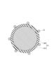
- FIG. 3 is a cross-sectional view showing the cross-sectional structure of a carrier.
- FIG. 1 is an exploded perspective view showing a configuration example of a polymer electrolyte fuel cell.
- FIG. 1 is an exploded perspective view schematically showing the structure of a membrane electrode assembly for a fuel cell according to an embodiment.
- 5 is an exploded perspective view schematically showing the structure of a polymer electrolyte fuel cell equipped with the membrane electrode assembly of FIG. 4.
- FIG. FIG. 1 is an exploded perspective view schematically showing the structure of a membrane electrode assembly for a fuel cell according to an embodiment.
- Electrode catalyst layer of the first embodiment The inventor of the present invention has conducted intensive studies on the initial power generation performance and durable power generation performance of polymer electrolyte fuel cells, and has found that these performances are greatly influenced by gas diffusivity and proton conductivity in the electrode catalyst layer. I found out that there is.
- a carrier coated with a polymer containing nitrogen atoms and a fibrous material containing nitrogen atoms in the electrode catalyst layer wide voids are formed to improve gas diffusivity.
- the electrode catalyst layer 10 according to the first embodiment is joined to the surface of the polymer electrolyte membrane 11, and includes a catalyst material 12, a carrier 13 supporting the catalyst material 12, It is configured to include a polymer electrolyte 14 and a fibrous substance 15.
- a gap 4 is formed in a portion where none of the above-mentioned components are present.
- the fibrous material 15 contains nitrogen atoms.
- the fibrous substance 15 is preferably a polymer having an azole structure.
- the azole structure refers to a five-membered heterocyclic structure containing one or more nitrogen atoms, such as an imidazole structure and an oxazole structure.
- the fibrous material 15 is preferably a polymer having a benzazole structure such as a benzimidazole structure or a benzoxazole structure.
- substances containing nitrogen atoms include polymers such as polybenzimidazole and polybenzoxazole.
- the fibrous material 15 contains nitrogen atoms
- interaction can occur between the lone pair of electrons of the nitrogen atoms and the protons of the polymer electrolyte.
- the proton conductivity in the membrane electrode assembly can be improved, and the output characteristics can be improved.
- the flexibility becomes high and the strength of the electrode catalyst layer 10 is improved.
- the thermal stability of the electrode catalyst layer 10 is improved.
- the mass ratio (content) of the fibrous material 15 in the electrode catalyst layer 10 is 2% by weight or more and 5% by weight or less.
- the mass proportion of the fibrous material 15 is more preferably 2% by weight or more and 3% by weight or less. If the mass proportion of the fibrous material 15 is smaller than the above range, the voids 4 may become narrower and sufficient drainage and gas diffusivity may not be ensured. Moreover, cracks may occur in the electrode catalyst layer 10, and the durability may decrease accordingly. If the mass ratio of the fibrous material 15 is larger than the above range, the proton conduction path by the polymer electrolyte 14 is blocked, which may not only increase the resistance but also cause water clogging and reduce durability. It may decrease.
- the mass percentage of the fibrous substance 15 contained in the electrode catalyst layer 10 can be obtained by the ratio of the weight after removing substances other than the substance by chemical and electrochemical methods to the weight before removal.
- catalytic materials can be dissolved by acids such as aqua regia containing strong oxidizing agents, and conductive supports can be burnt out by high potentials.
- polymer electrolytes and polymer electrolyte membranes can be decomposed using hydrogen peroxide or the like.
- the average fiber diameter of the fibrous material 15 included in the electrode catalyst layer 10 according to the first embodiment is preferably 50 nm or more and 400 nm or less. By setting the fiber diameter within this range, it is possible to increase the voids 4 in the electrode catalyst layer 10 and to suppress a decrease in proton conductivity, making it possible to increase output. If the average fiber diameter of the fibrous material 15 is smaller than the above range, the fibrous material may block the voids and sufficient drainage and gas diffusivity may not be ensured. Furthermore, if the average fiber diameter of the fibrous material 15 is larger than the above range, conduction of electrons and protons by the carrier 13 and the polymer electrolyte 14 may be inhibited, resulting in an increase in resistance.
- the fiber length of the fibrous substance 15 is preferably 1 ⁇ m or more and 80 ⁇ m, more preferably 5 ⁇ m or more and 70 ⁇ m or less.
- the fiber diameter of the fibrous material 15 is determined by, for example, measuring the diameter of the fibrous material 15 whose cross section is exposed when the cross section of the electrode catalyst layer 10 is observed using a scanning electron microscope (SEM). You can get it by doing.
- SEM scanning electron microscope
- the fiber diameter of the fibrous material 15 can be obtained by measuring the diameter of a perfect circle fitted along the short axis.
- the average fiber diameter can be obtained by measuring the fiber diameters of the fibrous material 15 at a plurality of locations, for example, 20 locations, and averaging them arithmetic.
- a method for exposing the cross section of the electrode catalyst layer 10 known methods such as ion milling and ultramicrotome can be used, for example.
- cryo-ion milling is performed while cooling the electrode catalyst layer 10 in order to reduce damage to the polymer electrolyte membrane 11 and the polymer electrolyte 14 that constitutes the electrode catalyst layer 10. It is particularly preferable to use
- the thickness of the electrode catalyst layer 10 is preferably 5 ⁇ m or more and 30 ⁇ m or less. When the thickness is thicker than 30 ⁇ m, cracks are likely to occur, and when used in a fuel cell, the diffusivity and conductivity of gas and generated water decrease, resulting in a decrease in output. Further, if the thickness is thinner than 5 ⁇ m, variations in layer thickness tend to occur, and the internal catalyst substance 12 and polymer electrolyte 14 tend to become non-uniform. Cracks on the surface of the electrode catalyst layer 10 and non-uniformity in thickness are undesirable because they are highly likely to adversely affect durability when used as a fuel cell and operated over a long period of time.
- the thickness of the electrode catalyst layer 10 can be measured, for example, by observing a cross section of the electrode catalyst layer 10 using a scanning electron microscope (SEM). A cross section of the electrode catalyst layer 10 is exposed.
- SEM scanning electron microscope
- known methods such as ion milling and ultramicrotome can be used.
- cryo-ion milling is performed while cooling the electrode catalyst layer 10 in order to reduce damage to the polymer electrolyte membrane 11 and the polymer electrolyte 14 that constitutes the electrode catalyst layer 10. It is particularly preferable to use
- Examples of the catalyst substance 12 include metals included in the platinum group, metals other than the platinum group, alloys of these metals, oxides, double oxides, and carbides.
- Metals included in the platinum group are platinum, palladium, ruthenium, iridium, rhodium, and osmium.
- Examples of metals other than the platinum group include iron, lead, copper, chromium, cobalt, nickel, manganese, vanadium, molybdenum, gallium, and aluminum.
- the average particle size of the catalyst can be between 2.0 and 10 nm.
- the carrier 13 has a conductive core 13A and a polymer layer 13B covering the conductive core.
- the carrier 13 supports the catalyst material 12 .
- the conductive core 13A is a carrier that has conductivity and can support the catalyst substance 12 without being corroded by the catalyst substance 12.
- An example of the conductive core 13A is carbon particles. Examples of carbon particles are carbon black, graphite, graphite, activated carbon, carbon nanotubes, carbon nanofibers, and fullerenes.
- the particle size of the carbon particles is preferably about 10 nm or more and 1000 nm or less, and more preferably about 10 nm or more and 100 nm or less.
- the particle size is 10 nm or more, the carbon particles do not clog the electrode catalyst layer 10 too densely, thereby suppressing deterioration of the gas diffusivity of the electrode catalyst layer 10.
- the particle size in this specification is, in principle, D50 of a volume-based frequency distribution determined by a laser diffraction/scattering method.
- the carrier 13 has a conductive core 13A such as carbon particles and a polymer layer 13B covering the conductive core 13A.
- the polymer of the polymer layer 13B contains nitrogen atoms. Examples of polymers containing nitrogen atoms are those explained in the section of fibrous substances containing nitrogen atoms.
- the polymer layer 13B and the fibrous substance 15 containing nitrogen atoms may be made of the same material, or may be made of different materials.
- the polymer may be polybenzimidazole.
- the film thickness of the polymer layer 13B may be 1 to 5 nm, or 2 to 3 nm.
- the coverage of the surface of the conductive core 13A by the polymer layer 13B is preferably 2% or more and 10% or less. If it is 11% or more, the coverage becomes excessive and the drainage performance may deteriorate. Moreover, if it is less than 2%, the polymer layer 13B will be insufficient, and the initial performance will not be improved.
- Such a carrier 13 can be obtained by bringing a conductive core 13A such as a carbon particle into contact with a solution of a nitrogen atom-containing polymer, and then drying the solvent from the conductive core 13A.
- solvents are DMSO (dimethylsulfoxide), DMAc (dimethylacetamide).
- polymer electrolyte As the polymer electrolyte 14 included in the polymer electrolyte membrane 11 and the electrode catalyst layer 10, an electrolyte having proton conductivity can be used.
- the polymer electrolyte for example, a fluorine-based polymer electrolyte and a hydrocarbon-based polymer electrolyte can be used.
- a polymer electrolyte having a tetrafluoroethylene skeleton can be used as the fluorine-based polymer electrolyte.
- An example of the polymer electrolyte having a tetrafluoroethylene skeleton is Nafion (registered trademark) manufactured by DuPont.
- hydrocarbon polymer electrolyte for example, sulfonated polyether ketone, sulfonated polyether sulfone, sulfonated polyether ether sulfone, sulfonated polysulfide, and sulfonated polyphenylene can be used.
- the polymer electrolyte contained in the polymer electrolyte membrane 11 and the polymer electrolyte 14 contained in the electrode catalyst layer 10 may be the same electrolyte or different electrolytes. However, when considering the interfacial resistance at the interface between the polymer electrolyte membrane 11 and the electrode catalyst layer 10 and the rate of dimensional change in the polymer electrolyte membrane 11 and the electrode catalyst layer 10 when the humidity changes, the polymer electrolyte membrane 11
- the polymer electrolyte contained in the electrode catalyst layer 10 and the polymer electrolyte 14 contained in the electrode catalyst layer 10 are preferably the same electrolytes or polymer electrolytes with similar coefficients of thermal expansion.
- composition of electrode catalyst layer The ratio of nitrogen atoms to the total of carbon atoms, nitrogen atoms, oxygen atoms, fluorine atoms, sulfur atoms, and platinum atoms contained in the electrode catalyst layer 10 needs to be 8 at% or more and 20 at% or less. As a result, the lone pair of electrons of the nitrogen atom interacts with the protons of the polymer electrolyte, thereby improving the proton conductivity in the electrode catalyst layer and improving the output characteristics. If the content of nitrogen atoms in the electrode catalyst layer 10 is smaller than the above range, the interaction with the sulfonic acid groups may be weakened, leading to a lack of proton conduction paths and increased resistance.
- the ratio of nitrogen atoms to the total of carbon atoms, nitrogen atoms, oxygen atoms, fluorine atoms, sulfur atoms, and platinum atoms contained in the electrode catalyst layer 10 is determined by, for example, It can be measured by performing elemental mapping using a transmission electron microscope (TEM-EDX) equipped with line spectroscopy.
- TEM-EDX transmission electron microscope
- the method for exposing the cross section was the same as that for observing the thickness of the electrode catalyst layer 10 described above, and elemental mapping was performed in the observation area of 150 nm x 150 nm.
- Electrode catalyst layer of second embodiment The inventors of the present invention have conducted intensive studies on the initial power generation performance and durable power generation performance of polymer electrolyte fuel cells, and have determined that the electrode catalyst layer contains a carrier coated with a polymer compound containing nitrogen atoms and a nitrogen atom-containing polymer compound.
- a fibrous substance made of a compound interaction between the lone pair of electrons of the nitrogen atom and the proton of the polymer electrolyte occurs, forming wide voids and improving gas diffusivity. Reduced proton conduction resistance.
- the mass transport properties and proton conductivity in the electrode catalyst layer were improved.
- the electrode catalyst layer 10 according to the second embodiment is bonded to the surface of a polymer electrolyte membrane 11, and includes a catalyst 12, a carrier 13 supporting the catalyst 12, and a polymer electrolyte layer 10. It is configured to include an electrolyte 14 and a fibrous substance 15. A gap 4 is formed in a portion where none of the above-mentioned components are present.
- the fibrous material 15 is made of a compound containing nitrogen atoms.
- the compound containing a nitrogen atom include a polymer compound containing a nitrogen atom.
- the "nitrogen atom-containing polymer compound" constituting the fibrous material 15 is preferably one in which the nitrogen atom exists in a state with a lone pair of electrons (that is, constitutes a Lewis base). be.
- the fibrous material 15 is preferably made of a polymer compound having an azole structure.
- the azole structure refers to a five-membered heterocyclic structure containing one or more nitrogen atoms, and includes, for example, an imidazole structure and an oxazole structure.
- the "nitrogen atom-containing compound" forming the fibrous material 15 is preferably a polymer compound having a benzazole structure such as a benzimidazole structure or a benzoxazole structure. Specific examples include polybenzimidazole and polybenzoxazole.
- the electrode catalyst layer 10 contains the fibrous material 15 made of a compound containing nitrogen atoms
- the proton conductivity in the membrane electrode assembly increases due to the interaction between the lone pair of nitrogen atoms and the protons of the polymer electrolyte. and the output characteristics are improved.
- the strength of the electrode catalyst layer 10 is improved due to the flexibility of the fibrous material 15.
- the thermal stability of the electrode catalyst layer 10 is improved.
- the content of the fibrous material 15 in the electrode catalyst layer 10 is 10% by mass or more and 20% by mass or less. If the content of the fibrous substance 15 is less than 10% by mass, cracks may occur in the electrode catalyst layer 10 and durability may decrease. When the content of the fibrous material 15 exceeds 20% by mass, the fibrous material 15 aggregates and the electrode catalyst layer 10 is likely to be clogged with water, and its durability may also be reduced.
- the content rate of the fibrous substance 15 in the electrode catalyst layer 10 can be obtained by the ratio of the mass after removing substances other than the fibrous substance 15 by chemical methods and electrochemical methods to the mass before removal.
- the catalyst 12 can be dissolved by an acid such as aqua regia containing a strong oxidizing agent, and the carrier 13 can be burned out by a high potential.
- the polymer electrolyte 14 and the polymer electrolyte membrane 11 can be decomposed using hydrogen peroxide or the like.
- the average fiber diameter of the fibrous material 15 included in the electrode catalyst layer 10 according to the second embodiment is preferably 50 nm or more and 400 nm or less. By setting the fiber diameter within this range, it is possible to increase the voids 4 in the electrode catalyst layer 10 and to suppress a decrease in proton conductivity, making it possible to increase output. If the average fiber diameter of the fibrous material 15 is smaller than the above range, the fibrous material may block the voids and sufficient drainage and gas diffusivity may not be ensured. Furthermore, if the average fiber diameter of the fibrous material 15 is larger than the above range, conduction of electrons and protons by the carrier 13 and the polymer electrolyte 14 may be inhibited, resulting in an increase in resistance.
- the fiber length of the fibrous substance 15 is preferably 1 ⁇ m or more and 80 ⁇ m, more preferably 5 ⁇ m or more and 70 ⁇ m or less.
- the fiber diameter of the fibrous material 15 is determined by, for example, measuring the diameter of the fibrous material 15 whose cross section is exposed when the cross section of the electrode catalyst layer 10 is observed using a scanning electron microscope (SEM). You can get it by doing.
- SEM scanning electron microscope
- the fiber diameter of the fibrous material 15 can be obtained by measuring the diameter of a perfect circle fitted along the short axis.
- the average fiber diameter can be obtained by measuring the fiber diameters of the fibrous material 15 at a plurality of locations, for example, 20 locations, and averaging them arithmetic.
- a method for exposing the cross section of the electrode catalyst layer 10 known methods such as ion milling and ultramicrotome can be used, for example.
- cryo-ion milling is performed while cooling the electrode catalyst layer 10 in order to reduce damage to the polymer electrolyte membrane 11 and the polymer electrolyte 14 that constitutes the electrode catalyst layer 10. It is particularly preferable to use
- the thickness of the electrode catalyst layer 10 is preferably 5 ⁇ m or more and 30 ⁇ m or less. When the thickness is thicker than 30 ⁇ m, cracks are likely to occur, and when used in a fuel cell, the diffusibility and conductivity of gas and generated water decrease, resulting in a decrease in output. Further, if the thickness is thinner than 5 ⁇ m, variations in layer thickness tend to occur, and the internal catalyst 12 and polymer electrolyte 14 tend to become non-uniform. Cracks on the surface of the electrode catalyst layer 10 and non-uniformity in thickness are undesirable because they are highly likely to have a negative effect on durability when used as a fuel cell and operated over a long period of time.
- the thickness of the electrode catalyst layer 10 can be measured, for example, by observing a cross section of the electrode catalyst layer 10 using a scanning electron microscope (SEM). A cross section of the electrode catalyst layer 10 is exposed.
- SEM scanning electron microscope
- known methods such as ion milling and ultramicrotome can be used.
- cryo-ion milling is performed while cooling the electrode catalyst layer 10 in order to reduce damage to the polymer electrolyte membrane 11 and the polymer electrolyte 14 that constitutes the electrode catalyst layer 10. It is particularly preferable to use
- Examples of the catalyst 12 include metals included in the platinum group, metals other than the platinum group, alloys of these metals, oxides, double oxides, and carbides.
- Metals included in the platinum group are platinum, palladium, ruthenium, iridium, rhodium, and osmium.
- Examples of metals other than the platinum group include iron, lead, copper, chromium, cobalt, nickel, manganese, vanadium, molybdenum, gallium, and aluminum.
- the average particle size of the catalyst is preferably 2.0 or more and 10 nm or less.
- the carrier 13 has a conductive core 13A and a layer 13B made of a polymer compound (hereinafter also referred to as a "polymer layer") covering the conductive core.
- the carrier 13 supports the catalyst 12.
- the conductive core 13A is a carrier that has conductivity and can support the catalyst 12 without being eroded by the catalyst 12.
- An example of the conductive core 13A is carbon particles. Examples of carbon particles are carbon black, graphite, graphite, activated carbon, carbon nanotubes, carbon nanofibers, and fullerenes.
- the particle size of the carbon particles is preferably about 10 nm or more and 1000 nm or less, and more preferably about 10 nm or more and 100 nm or less.
- the particle size is 10 nm or more, the carbon particles do not clog the electrode catalyst layer 10 too densely, thereby suppressing deterioration of the gas diffusivity of the electrode catalyst layer 10.
- the particle size in this specification is, in principle, D50 of a volume-based frequency distribution determined by a laser diffraction/scattering method.
- the carrier 13 has a conductive core 13A such as carbon particles and a polymer layer 13B covering the conductive core 13A.
- the polymer layer 13B is made of a polymer compound containing nitrogen atoms.
- nitrogen atom-containing polymer compound constituting the polymer layer 13B, those exemplified as the “nitrogen atom-containing polymer compound” that can be suitably used in the fibrous material 15 can be used.
- the polymer layer 13B and the fibrous substance 15 may be made of the same material, or may be made of different materials.
- the "nitrogen atom-containing polymer compound" constituting the polymer layer 13B may be polybenzimidazole.
- the film thickness of the polymer layer 13B may be 1 to 5 nm, or 2 to 3 nm.
- the coverage of the surface of the conductive core 13A by the polymer layer 13B is preferably 2% or more and 10% or less. If it is 11% or more, the coverage becomes excessive and the drainage performance may deteriorate. Moreover, if it is less than 2%, the polymer layer 13B will be insufficient, and the initial performance will not be improved.
- Such a carrier 13 can be obtained by bringing a conductive core 13A such as a carbon particle into contact with a solution of a nitrogen atom-containing polymer, and then drying the solvent from the conductive core 13A.
- solvents are DMSO (dimethylsulfoxide), DMAc (dimethylacetamide).
- polymer electrolyte As the polymer electrolyte 14 included in the polymer electrolyte membrane 11 and the electrode catalyst layer 10, an electrolyte having proton conductivity can be used.
- the polymer electrolyte for example, a fluorine-based polymer electrolyte and a hydrocarbon-based polymer electrolyte can be used.
- a polymer electrolyte having a tetrafluoroethylene skeleton can be used as the fluorine-based polymer electrolyte.
- An example of the polymer electrolyte having a tetrafluoroethylene skeleton is Nafion (registered trademark) manufactured by DuPont.
- hydrocarbon polymer electrolyte for example, sulfonated polyether ketone, sulfonated polyether sulfone, sulfonated polyether ether sulfone, sulfonated polysulfide, and sulfonated polyphenylene can be used.
- the polymer electrolyte contained in the polymer electrolyte membrane 11 and the polymer electrolyte 14 contained in the electrode catalyst layer 10 may be the same electrolyte or different electrolytes. However, when considering the interfacial resistance at the interface between the polymer electrolyte membrane 11 and the electrode catalyst layer 10 and the rate of dimensional change in the polymer electrolyte membrane 11 and the electrode catalyst layer 10 when the humidity changes, the polymer electrolyte membrane 11
- the polymer electrolyte contained in the electrode catalyst layer 10 and the polymer electrolyte 14 contained in the electrode catalyst layer 10 are preferably the same electrolytes or polymer electrolytes with similar coefficients of thermal expansion.
- the electrode catalyst layer 10 has a composition containing carbon atoms, nitrogen atoms, oxygen atoms, fluorine atoms, sulfur atoms, and platinum atoms, and the ratio of nitrogen atoms to the total number of these atoms (hereinafter also referred to as "nitrogen atomic ratio”) ) is 20 atomic % (at %) or more and 35 atomic % (at %) or less.
- the proportion of nitrogen atoms in the composition of the electrode catalyst layer 10 is less than 20 at %, the interaction between the lone pair of nitrogen atoms and the protons of the polymer electrolyte is weakened, and the proton conduction path is insufficient. Resistance may increase.
- the proportion of nitrogen atoms exceeds 35 at % due to an increase in the content of fibrous substances, the intertwining and aggregation of fibers will clog the voids, making it impossible to ensure sufficient drainage and gas diffusion. This may lead to a decrease in power generation performance and durability.
- the nitrogen atomic ratio in the composition of the electrode catalyst layer 10 depends on the type and amount of the "nitrogen-containing polymer compound" constituting the polymer layer 13B covering the conductive core 13A, the amount added to the electrode catalyst layer 10, and the fibrous material. It can be controlled by the type of "nitrogen-containing compound” constituting the nitrogen-containing compound 15 and the amount added to the electrode catalyst layer 10.
- the proportion of nitrogen atoms in the composition of the electrode catalyst layer 10 can be determined, for example, by element mapping a cross section of the electrode catalyst layer 10 using a transmission electron microscope (TEM-EDX) equipped with an energy dispersive X-ray spectrometer. It can be measured by doing.
- the method of exposing the cross section is the same as the above-described observation of the thickness of the electrode catalyst layer 10, and elemental mapping is performed in the observation area of 150 nm x 150 nm.
- FIG. 3 is an exploded perspective view showing a configuration example of a polymer electrolyte fuel cell 3 equipped with a membrane electrode assembly 1 having an electrode catalyst layer 10 according to the first or second embodiment.
- the membrane electrode assembly 1 includes a polymer electrolyte membrane 11 and electrode catalyst layers 10C and 10A bonded to the front and back surfaces of the polymer electrolyte membrane 11, respectively.
- the electrode catalyst layer 10C formed on the upper surface (front surface) of the polymer electrolyte membrane 11 is a cathode side electrode catalyst layer that constitutes an oxygen electrode, and is formed on the lower surface (back surface) of the polymer electrolyte membrane 11.
- the electrode catalyst layer 10A is an anode side electrode catalyst layer that constitutes a fuel electrode.
- the pair of electrode catalyst layers 10C and 10A may be abbreviated as "electrode catalyst layer 10" if there is no need to distinguish them.
- the electrode catalyst layer 10 of the first embodiment or the second embodiment may be provided on at least one surface of the polymer electrolyte membrane 11.
- the electrode catalyst layer 10 of the first embodiment may be provided on both sides of the polymer electrolyte membrane 11, and the electrode catalyst layer 10 of the second embodiment may be provided on both sides of the polymer electrolyte membrane 11.
- the electrode catalyst layer 10 of the first embodiment may be provided on one side of the polymer electrolyte membrane 11, and the electrode catalyst layer 10 of the second embodiment may be provided on the other side. It is suitable that the electrode catalyst layer 10 of the first embodiment is a cathode side electrode catalyst layer that constitutes an oxygen electrode.
- the electrode catalyst layer 10 of the second embodiment is preferably an anode side electrode catalyst layer constituting a fuel electrode.
- the cathode side electrode catalyst layer constituting the oxygen electrode of the polymer electrolyte membrane 11 is the electrode catalyst layer 10 of the first embodiment, and the anode side electrode catalyst layer constituting the fuel electrode of the polymer electrolyte membrane 11 is the second embodiment. It is also suitable that the electrode catalyst layer 10 is as follows. Furthermore, in order to prevent gas leakage from the outer peripheral portion of the polymer electrolyte membrane 11 to which the electrode catalyst layer 10 is not bonded, a gasket 16C on the oxygen electrode side and a gasket 16A on the fuel electrode side are arranged in the membrane electrode assembly 1. There is.
- a catalyst ink is prepared.
- a catalyst ink is prepared by mixing the catalyst material 12, the carrier 13, the polymer electrolyte 14, and the fibrous material 15 in a dispersion medium, and then subjecting the mixture to a dispersion treatment.
- the dispersion treatment can be performed using, for example, a planetary ball mill, a bead mill, an ultrasonic homogenizer, or the like.
- the polymer electrolyte 14 is dissolved in the dispersion medium of the catalyst ink in such a manner that it does not erode the catalyst substance 12, the carrier 13, the polymer electrolyte 14, and the fibrous substance 15, and the dispersion medium has high fluidity.
- a solvent capable of dispersing the polymer electrolyte 14 as a fine gel can be used.
- the dispersion medium may contain water.
- the catalyst ink includes a volatile liquid organic solvent. Since there is a risk of ignition when the solvent is a lower alcohol, water is preferably mixed with such a solvent. Water can be mixed with the solvent within a range that does not cause the catalyst ink to become cloudy or gelatinous due to separation of the polymer electrolyte 14.
- the electrode catalyst layer 10 is formed on the base material.
- the polymer electrolyte membrane 11 or a transfer base material can be used as the base material.
- the electrode catalyst layer 10 is formed by directly applying catalyst ink to the surface of the polymer electrolyte membrane 11 and then removing the solvent from the coating film of the catalyst ink. A forming method can be used.
- the catalyst layer is transferred from the catalyst layer-coated base material to the polymer electrolyte membrane 11 by applying catalyst ink on the transfer base material and then drying it, thereby forming the catalyst layer-coated base material. Make the material. Thereafter, for example, by heating and pressurizing the surface of the electrode catalyst layer 10 in the base material with the catalyst layer and the polymer electrolyte membrane 11 in contact with each other, the electrode catalyst layer 10 and the polymer electrolyte membrane 11 are brought into contact with each other. 11 are joined. By joining the electrode catalyst layers 10 to both sides of the polymer electrolyte membrane 11, the membrane electrode assembly 1 can be manufactured.
- Various coating methods can be used to apply the catalyst ink to the base material.
- the coating method include die coating, roll coating, curtain coating, spray coating, and squeegee coating.
- die coating is preferable because the film thickness in the middle of the coating period is stable and intermittent coating is possible.
- a method for drying the coating film of the catalyst ink for example, drying using a hot air oven, drying using IR (far infrared rays), drying using a hot plate, drying under reduced pressure, etc. can be used.
- the drying temperature is 40°C or more and 200°C or less, preferably about 40°C or more and 120°C or less.
- the drying time is 0.5 minutes or more and 1 hour or less, preferably about 1 minute or more and 30 minutes or less.
- the electrode catalyst layer 10 When forming the electrode catalyst layer 10 on a transfer base material and transferring and bonding the catalyst layer (electrode catalyst layer 10) from the base material with the catalyst layer to the polymer electrolyte membrane 11, transfer of the electrode catalyst layer 10 is performed. At times, the pressure and temperature applied to the electrode catalyst layer 10 affect the power generation performance of the membrane electrode assembly 1. In order to obtain a membrane electrode assembly with high power generation performance, the pressure applied to the electrode catalyst layer 10 is preferably 0.1 MPa or more and 20 MPa or less. By setting the pressure to 20 MPa or less, the electrode catalyst layer 10 is prevented from being excessively compressed.
- the temperature at the time of bonding is determined based on the temperature of the polymer contained in the polymer electrolyte membrane 11 or the electrode catalyst layer 10, considering the improvement of the bondability of the interface between the polymer electrolyte membrane 11 and the electrode catalyst layer 10 and the suppression of interfacial resistance.
- the temperature is near the glass transition point of the electrolyte 14.
- a polymer film or a sheet formed of a fluororesin can be used as the transfer substrate.
- Fluorine resins have excellent transferability.
- fluororesins include ethylenetetrafluoroethylene copolymer (ETFE), tetrafluoroethylene-hexafluoropropylene copolymer (FEP), tetrafluoroperfluoroalkyl vinyl ether copolymer (PFA), and polytetrafluoroethylene copolymer (ETFE) Examples include fluoroethylene (PTFE).
- polymers that form polymer films include polyimide, polyethylene terephthalate, polyamide (nylon (registered trademark)), polysulfone, polyethersulfone, polyphenylene sulfide, polyether/etherketone, polyetherimide, and polyarylate. , and polyethylene naphthalate.
- a gas diffusion layer can also be used for the transfer base material.
- the electrode catalyst layer 10 can have sufficient gas diffusivity and proton conductivity.
- the blending ratio of the polymer electrolyte 14 in the electrode catalyst layer 10 is preferably about the same to about half the weight of the carrier 13.
- the blending ratio of the fibrous substance 15 is preferably equal to or less than the weight of the carrier 13. It is preferable that the solid content ratio of the catalyst ink be as high as possible within a range that can be applied to a thin film.
- FIG. 3 shows an example of the configuration of a single cell, and the polymer electrolyte fuel cell 3 is not limited to this configuration, and may have a configuration in which a plurality of single cells are stacked.
- the polymer electrolyte fuel cell 3 includes a membrane electrode assembly 1, a gas diffusion layer 17C on the oxygen electrode side, and a gas diffusion layer 17A on the fuel electrode side.
- the gas diffusion layer 17C is disposed opposite to the electrode catalyst layer 10C, which is the cathode electrode catalyst layer on the oxygen electrode side of the membrane electrode assembly 1.
- the gas diffusion layer 17A is arranged to face the electrode catalyst layer 10A, which is the anode side electrode catalyst layer on the fuel electrode side of the membrane electrode assembly 1.
- the electrode catalyst layer 10C and the gas diffusion layer 17C constitute an oxygen electrode 2C
- the electrode catalyst layer 10A and the gas diffusion layer 17A constitute a fuel electrode 2A.
- the polymer electrolyte fuel cell 3 includes a separator 18C arranged to face the oxygen electrode 2C, and a separator 18A arranged to face the fuel electrode 2A.
- the separator 18C has a gas flow path 19C for reactant gas flow formed on the surface facing the gas diffusion layer 17C, and a cooling water flow path formed on the surface opposite to the surface where the gas flow path 19C is formed.
- a water flow path 20C is provided.
- the separator 18A has the same configuration as the separator 18C, and includes a gas flow path 19A formed on a surface facing the gas diffusion layer 17A, and a surface opposite to the surface on which the gas flow path 19A is formed.
- the cooling water flow path 20A is formed in the cooling water flow path 20A.
- Separators 18C and 18A are made of an electrically conductive and gas impermeable material.
- an oxidizing agent such as air or oxygen is supplied to the oxygen electrode 2C through the gas flow path 19C of the separator 18C, and fuel containing hydrogen is supplied through the gas flow path 19A of the separator 18A. Gas or organic fuel is supplied to the fuel electrode 2A to generate electricity.
- the polymer electrolyte fuel cell 3 according to the present embodiment has sufficient drainage performance and gas diffusivity, and has a long-term high It becomes possible to demonstrate power generation performance and high durability.
- the polymer electrolyte fuel cell 3 has sufficient gas diffusivity and proton conductivity during operation, and exhibits high power generation performance and high durability over a long period of time. It is possible to provide an electrode catalyst layer 10, a membrane electrode assembly 1, and a polymer electrolyte fuel cell 3 that can perform the following steps. Therefore, the present invention can be suitably used in stationary cogeneration systems, fuel cell vehicles, etc. that utilize polymer electrolyte fuel cells, and has great industrial utility value.
- Example A1 a catalyst-supporting carrier (platinum loading rate of 50% by weight) in which platinum (catalyst material) was supported on Ketjen black (carrier core) coated with a polymer (polymer layer) containing nitrogen atoms; Water, 1-propanol, a polymer electrolyte (20% Nafion (registered trademark) dispersion, manufactured by Wako Pure Chemical Industries, Ltd.), and a fibrous material containing nitrogen atoms (polyazole, diameter 100-400 nm) were mixed.
- This mixture was subjected to a dispersion treatment using a planetary ball mill at 300 rpm for 120 minutes. At that time, a zirconia ball having a diameter of 5 mm was added to about one third of the zirconia container.
- the weight of the polymer electrolyte was 100% by weight with respect to the weight of the carbon core in the catalyst-supporting carrier, and the weight of the fibrous material containing nitrogen atoms was 3% by weight with respect to the weight of the electrode catalyst layer.
- a catalyst ink was prepared by adjusting the proportion of water in the medium to 70% by weight and the solid content concentration to 12% by weight.
- a coating film was formed by applying the catalyst ink to one side of a polymer electrolyte membrane (Nafion (registered trademark) 211, manufactured by DuPont) using a slit die coater to a thickness of 200 ⁇ m.
- a polymer electrolyte membrane Nafion (registered trademark) 211, manufactured by DuPont
- the polymer electrolyte membrane on which the coating film was formed was dried in a hot air oven at 80° C. until the coating film became tack free, thereby forming a cathode side electrode catalyst layer.
- a coating film was formed by applying catalyst ink to the opposite surface of the polymer electrolyte membrane using a slit die coater to a thickness of 50 ⁇ m.
- Example 1 The nitrogen element composition ratio in the electrode catalyst layer was 12%.
- Example A2 Same as Example A1, except that when preparing the catalyst ink, the amount of the fibrous material containing nitrogen atoms was 2/3 times that of Example A1 (2% by weight with respect to the weight of the electrode catalyst layer). A membrane electrode assembly of Example A2 was obtained by the method described above. The nitrogen element composition ratio in the catalyst layer was 8%.
- Example A3 Same as Example A1, except that when preparing the catalyst ink, the amount of the fibrous material containing nitrogen atoms was 5/3 times that of Example A1 (5% by weight with respect to the weight of the electrode catalyst layer).
- a membrane electrode assembly of Example A3 was obtained by the method described above. The nitrogen element composition ratio in the catalyst layer was 20%.
- Example A1 Same as Example A1, except that when preparing the catalyst ink, the amount of the fibrous material containing nitrogen atoms was 1/3 times that of Example A1 (1% by weight with respect to the weight of the electrode catalyst layer). A membrane electrode assembly of Comparative Example A1 was obtained by the method. The nitrogen element composition ratio in the catalyst layer was 5%.
- Example A2 The same method as Example A1 was used, except that when preparing the catalyst ink, the amount of the fibrous material containing nitrogen atoms was twice that of Example A1 (1% by weight based on the weight of the electrode catalyst layer). A membrane electrode assembly of Comparative Example A2 was obtained. The nitrogen element composition ratio in the catalyst layer was 25%.
- Comparative example A3 When preparing the catalyst ink, instead of using a catalyst in which platinum is supported on Ketjen black coated with a nitrogen atom-containing polymer, a platinum carbon-supported catalyst that is not coated with a nitrogen atom-containing polymer (a membrane electrode assembly of Comparative Example A3 was obtained in the same manner as in Example A1, except that TEC10E50E (manufactured by Tanaka Kikinzoku Kogyo Co., Ltd.) was used. The nitrogen element composition rate in the catalyst layer was 11% by weight.
- Comparative example A4 When preparing the catalyst ink, instead of using a catalyst in which platinum is supported on Ketjen black coated with a nitrogen atom-containing polymer, a platinum carbon-supported catalyst that is not coated with a nitrogen atom-containing polymer (a membrane electrode assembly of Comparative Example A4 was obtained in the same manner as in Example A2, except that TEC10E50E (manufactured by Tanaka Kikinzoku Kogyo Co., Ltd.) was used. The nitrogen element composition rate in the catalyst layer was 5% by weight.
- Comparative example A5 When preparing the catalyst ink, instead of using a catalyst in which platinum is supported on Ketjen black coated with a nitrogen atom-containing polymer, a platinum carbon-supported catalyst that is not coated with a nitrogen atom-containing polymer (a membrane electrode assembly of Comparative Example A5 was obtained in the same manner as in Example A3, except that TEC10E50E (manufactured by Tanaka Kikinzoku Kogyo Co., Ltd.) was used. The nitrogen element composition rate in the catalyst layer was 18% by weight.
- Example A6 The same procedure as in Example A1 was carried out, except that carbon nanofibers (VGCF-H (registered trademark), manufactured by Showa Denko Packaging Co., Ltd.) were added instead of the fibrous material containing nitrogen atoms when preparing the catalyst ink. By this method, a membrane electrode assembly of Comparative Example A6 was obtained. The nitrogen element composition ratio in the catalyst layer was 0%.
- Example A7 The same process as Example A2 was carried out, except that carbon nanofibers (VGCF-H (registered trademark), manufactured by Showa Denko Packaging Co., Ltd.) were added instead of the fibrous material containing nitrogen atoms when preparing the catalyst ink. By this method, a membrane electrode assembly of Comparative Example A7 was obtained. The nitrogen element composition ratio in the catalyst layer was 0%.
- Example A8 The same process as Example A3 was carried out, except that carbon nanofibers (VGCF-H (registered trademark), manufactured by Showa Denko Packaging Co., Ltd.) were added instead of the fibrous material containing nitrogen atoms when preparing the catalyst ink. By this method, a membrane electrode assembly of Comparative Example A8 was obtained. The nitrogen element composition ratio in the catalyst layer was 0%.
- the nitrogen element composition ratio in the electrode catalyst layer was was 8 at% or more and 20 at% or less, and the weight ratio of the fibrous material was 2% or more and 5% or less.
- the power generation performance and durability were both rated " ⁇ ". That is, in Examples A1 to A3, membrane electrode assemblies capable of forming fuel cells with excellent power generation performance and durability were obtained.
- the nitrogen element composition ratio in the electrode catalyst layer was not 8 at% or more and 20 at% or less, and the weight ratio of the fibrous material was not 2% or more and 5% or less.
- the power generation performance was rated " ⁇ "
- the durability was rated "x”.
- Polymer electrolyte 20% Nafion (registered trademark) dispersion (manufactured by Fuji Film Wako Pure Chemical Industries, Ltd.)
- Fibrous substance polybenzimidazole (a polymeric compound containing nitrogen atoms) fiber with an average fiber diameter of 150 nm (diameter 100-400 nm) and a fiber length of 15 ⁇ m.
- Dispersion medium mixture of water and 1-propanol at a mass ratio of 70:30
- a mixed solution was obtained by mixing the catalyst-supported particles, the polymer electrolyte, the fibrous material, and the dispersion medium.
- the blending amount of the polymer electrolyte was set to be 100 parts by mass with respect to 100 parts by mass of the carrier (conductive core) in the catalyst-supported particles.
- the amount of the fibrous material was determined so that the content in the dried ink coating (electrode catalyst layer) would be as shown in Table 2. For example, in No. 2, the blending amount of the fibrous material was set to be 10% by mass of the total solid content so that the content of the fibrous material in the electrode catalyst layer was 10% by mass. Further, the amount of the dispersion medium added was adjusted so that the solid content concentration was 12% by mass.
- a catalyst ink was prepared by dispersing this liquid mixture. This mixture was subjected to a dispersion treatment using a planetary ball mill at 300 rpm for 120 minutes. At that time, a zirconia ball having a diameter of 5 mm was added to about one third of the zirconia container.
- a coating film was formed by applying the obtained catalyst ink to one side of a polymer electrolyte membrane (Nafion (registered trademark) 211, manufactured by DuPont) using a slit die coater to a thickness of 200 ⁇ m.
- a polymer electrolyte membrane Nafion (registered trademark) 211, manufactured by DuPont
- the polymer electrolyte membrane on which the coating film was formed was dried in a hot air oven at 80° C. until the coating film became tack free, thereby forming a cathode side electrode catalyst layer.
- the obtained catalyst ink was applied to the opposite surface of the polymer electrolyte membrane to a thickness of 50 ⁇ m using a slit die coater to form a coating film.
- the polymer electrolyte membrane on which the coating film was formed was dried in a hot air oven at 80° C. until the coating film became tack free, thereby forming an anode-side electrode catalyst layer.
- the solid body has an electrode catalyst layer that satisfies the configuration of one embodiment of the present invention (nitrogen atomic ratio is 20 at% or more and 35 at% or less, and the content of fibrous material is 10 mass % or more and 20 mass % or less). It can be seen that the polymer fuel cell provides good power generation performance and has excellent durability.
- the membrane electrode assembly 111 includes a polymer electrolyte membrane 101 and an electrode catalyst layer 102 (in FIG. 4, the upper side ) and an electrode catalyst layer 103 (shown at the bottom in FIG. 4). Further, each electrode catalyst layer 102, 103 includes catalyst-supported particles and an ionomer.
- At least one of the pair of electrode catalyst layers 102 and 103 further includes carbon fibers having a coating layer formed mainly of polybenzimidazole.
- Polybenzimidazole is a polymer that has an affinity for both ionomers and carbon.
- An electrocatalyst layer containing catalyst-supported particles, an ionomer, and carbon fibers having a coating layer formed mainly of polybenzimidazole will also be referred to as an "improved electrocatalyst layer" below.
- both of the pair of electrocatalyst layers 102, 103 are improved electrocatalyst layers.
- the term "main component” refers to a component that accounts for 50% by mass or more of the whole, and may be 70% by mass or more, 80% by mass or more, or 90% by mass or more.
- the carbon fiber contained in the improved electrode catalyst layer is preferably vapor grown carbon fiber (VGCF).
- the diameter of the carbon fibers contained in the improved electrode catalyst layer is preferably 10 nm or more and 1 ⁇ m or less.
- the improved electrode catalyst layer with the above structure has high mechanical properties and improved durability, such as suppressing the occurrence of cracks due to the entanglement of carbon fibers.
- a coating layer on the surface of the carbon fiber mainly composed of polybenzimidazole which has an affinity for both ionomers and carbon, the mechanical properties are further improved, and the ionomer on the surface of the coating layer A proton conduction path is formed, resulting in high power generation performance.
- a coating layer mainly composed of polybenzimidazole is not formed on the surface of the carbon fiber, the mechanical properties of the electrode catalyst layer are insufficient and it is difficult to suppress the occurrence of cracks. It is estimated that durability cannot be improved.
- the ionomer is dispersed, it is presumed that the formation of proton conduction paths is inhibited, making it impossible to improve power generation performance.
- the carbon fiber is not vapor grown carbon fiber (VGCF), it is estimated that it is difficult to form an annual ring structure in which carbon surfaces are laminated in a concentric cylindrical shape, and the affinity with the coating layer may not be sufficient.
- VGCF vapor grown carbon fiber
- the diameter of the carbon fiber is less than 10 nm, it may be difficult to improve mechanical properties. Furthermore, it is estimated that if the diameter of the carbon fiber exceeds 1 ⁇ m, it may not be possible to disperse it as an ink.
- the electrode catalyst layers 102 and 103 are improved electrode catalyst layers, cracks in the electrode catalyst layer may occur due to the entanglement of carbon fibers and the presence of a coating layer that has affinity for both the ionomer and carbon, which causes a decrease in durability. High mechanical properties and improved durability can be obtained, such as by suppressing the occurrence of heat generation.
- a polymer electrolyte fuel cell 112 shown in FIG. 5 includes a pair of gas diffusion layers 104 and 105.
- Gas diffusion layer 104 is arranged to face electrode catalyst layer 102 of membrane electrode assembly 111 .
- Gas diffusion layer 105 is arranged to face electrode catalyst layer 103.
- An air electrode (cathode, positive electrode) 106 is formed by the electrode catalyst layer 102 and the gas diffusion layer 104.
- the electrode catalyst layer 103 and the gas diffusion layer 105 form a fuel electrode (anode, negative electrode) 107.
- a pair of separators 110a and 110b are arranged outside the gas diffusion layers 104 and 105, respectively. That is, the membrane electrode assembly 111 is sandwiched between a pair of separators 110a and 110b in the thickness direction of the membrane electrode assembly 111.
- the separators 110a, 110b are provided with gas flow paths 108a, 108b for gas distribution, and cooling water flow paths 109a, 109b for cooling water distribution.
- Separators 110a and 110b are made of a conductive and impermeable material.
- hydrogen gas is supplied as a fuel gas to the gas flow path 108b of the separator 110b facing the fuel electrode 107.
- the gas flow path 108a of the separator 110a facing the air electrode 106 is supplied with, for example, oxygen gas as an oxidant gas.
- An electromotive force can be generated between the fuel electrode 107 and the air electrode 106 by causing the hydrogen of the fuel gas and the oxygen of the oxidant gas to react with each other at the electrode in the presence of a catalyst.
- a pair of separators 110a and 110b sandwich a polymer electrolyte membrane 101, a pair of electrode catalyst layers 102 and 103, and a pair of gas diffusion layers 104 and 105.
- the polymer electrolyte fuel cell 112 shown in FIG. 2 is an example of a fuel cell having a single cell structure, but the polymer electrolyte fuel cell has a plurality of cells stacked one on top of the other with a separator 110a or a separator 110b in between. It may have a structure.
- the improved electrode catalyst layer is manufactured by a method including the following first to third steps.
- the first step is a step of forming a coating layer containing polybenzimidazole as a main component on the carbon fiber.
- the second step is a step of manufacturing a catalyst ink containing catalyst-supported particles, an ionomer, the carbon fiber obtained in the first step, and a solvent.
- the third step is a step of forming an improved electrode catalyst layer by applying the catalyst ink obtained in the second step onto a base material and drying the solvent. Note that an electrode catalyst layer other than the improved electrode catalyst layer may also be manufactured using the same process.
- a membrane electrode assembly 111 is obtained by attaching the pair of produced electrode catalyst layers 102 and 103 to the upper and lower surfaces of the polymer electrolyte membrane 101.
- the polymer electrolyte membrane 101 may be anything that has proton conductivity, such as a fluorine-based polymer electrolyte membrane or a hydrocarbon-based polymer electrolyte membrane.
- fluoropolymer electrolyte membrane examples include Nafion (registered trademark) manufactured by DuPont, Flemion (registered trademark) manufactured by Asahi Glass Co., Ltd., Aciplex (registered trademark) manufactured by Asahi Kasei Corporation, and Gore Select (registered trademark) manufactured by Gore. etc. can be used.
- hydrocarbon polymer electrolyte membrane for example, electrolyte membranes such as sulfonated polyetherketone, sulfonated polyethersulfone, sulfonated polyetherethersulfone, sulfonated polysulfide, and sulfonated polyphenylene can be used.
- electrolyte membranes such as sulfonated polyetherketone, sulfonated polyethersulfone, sulfonated polyetherethersulfone, sulfonated polysulfide, and sulfonated polyphenylene can be used.
- Nafion (registered trademark) material manufactured by DuPont as the polymer electrolyte membrane 1.
- the electrode catalyst layers 102 and 103 are formed on both sides of the polymer electrolyte membrane 101 using catalyst ink.
- the catalyst ink for the electrode catalyst layers 102 and 103 includes catalyst-supporting particles made of carbon particles on which catalysts are supported, an ionomer, carbon fibers, and a solvent.
- the ionomer contained in the catalyst ink may be any ionomer as long as it has proton conductivity.
- the same material as the polymer electrolyte membrane 1 can be used for the ionomer.
- a fluorine-based polymer electrolyte or a hydrocarbon-based polymer electrolyte can be used as the ionomer.
- the fluorine-based polymer electrolyte for example, Nafion (registered trademark) material manufactured by DuPont, etc. can be used.
- hydrocarbon polymer electrolyte for example, electrolytes such as sulfonated polyether ketone, sulfonated polyether sulfone, sulfonated polyether ether sulfone, sulfonated polysulfide, and sulfonated polyphenylene can be used.
- electrolytes such as sulfonated polyether ketone, sulfonated polyether sulfone, sulfonated polyether ether sulfone, sulfonated polysulfide, and sulfonated polyphenylene
- Nafion (registered trademark) material manufactured by DuPont as the fluoropolymer electrolyte.
- platinum group elements As the catalyst (hereinafter sometimes referred to as catalyst particles or catalyst) used in this embodiment, platinum group elements, metals, alloys, oxides, and double oxides of these metals can be used.
- platinum group elements include platinum, palladium, ruthenium, iridium, rhodium, and osmium
- metals include iron, lead, copper, chromium, cobalt, nickel, manganese, vanadium, molybdenum, gallium, and aluminum.
- the double oxide herein refers to an oxide consisting of two types of metals.
- the catalyst particles are one or more metals selected from platinum, gold, palladium, rhodium, ruthenium, and iridium, they have excellent electrode reactivity and can perform electrode reactions efficiently and stably. can.
- the catalyst particles are one or more metals selected from platinum, gold, palladium, rhodium, ruthenium, and iridium
- the polymer electrolyte fuel cell 112 equipped with the electrode catalyst layers 102 and 103 It is preferable because it exhibits high power generation characteristics.
- Carbon particles are generally used as the electron-conductive powder, ie, the carrier, that supports the above-mentioned catalyst.
- the type of carbon particles is not limited as long as they are fine particles, have conductivity, and are not affected by the catalyst.
- carbon particles for example, carbon black, graphite, graphite, activated carbon, carbon fiber, carbon nanotube, and fullerene can be used.
- the average particle diameter of the carbon particles is preferably within the range of 10 nm or more and 1000 nm or less, and more preferably within the range of 10 nm or more and 100 nm or less.
- the average particle diameter is the average particle diameter determined from a SEM image. It is preferable that the average particle diameter of the carbon particles is within the range of 10 nm or more and 1000 nm or less because the activity and stability of the catalyst are improved.
- the average particle diameter of the carbon particles is within the range of 10 nm or more and 1000 nm or less, electron conduction paths are likely to be formed, and the gas diffusivity and catalyst utilization rate of the two electrode catalyst layers 102 and 103 are increased. This is preferable because it improves.
- the catalyst-supported particles described above may be provided with a hydrophobic coating.
- the catalyst-supported particles may be covered with a hydrophobic coating.
- the hydrophobic coating has a thickness sufficient to allow the reaction gas to pass through.
- the thickness of the hydrophobic film is preferably 40 nm or less. If it becomes thicker than this, the supply of reaction gas to the active sites may be inhibited.
- the hydrophobic coating is 40 nm or less, the reaction gas can sufficiently permeate through the hydrophobic coating, so that hydrophobicity can be imparted to the catalyst-supported particles.
- the thickness of the hydrophobic coating covering the catalyst-supported particles is preferably such that it sufficiently repels the generated water.
- the thickness of the hydrophobic film is preferably 2 nm or more. If the hydrophobic coating becomes thinner than this, the produced water may remain and the supply of reaction gas to the active sites may be inhibited. That is, by having a hydrophobic coating having a thickness of 2 nm or more, retention of generated water is suppressed, thereby suppressing the supply of reaction gas to the active sites from being inhibited.
- the hydrophobic film covering the catalyst-supporting particles is formed, for example, from a fluorine-based compound having at least one polar group.
- the polar group include a hydroxyl group, an alkoxy group, a carboxyl group, an ester group, an ether group, a carbonate group, and an amide group. Due to the presence of the polar group, the fluorine-based compound can be immobilized on the outermost surface of the electrode catalyst layer.
- the portion other than the polar group in the fluorine-based compound preferably has a structure consisting of fluorine and carbon because of its high hydrophobicity and chemical stability. However, the structure is not limited to this, as long as the hydrophobic coating has sufficient hydrophobicity and chemical stability.
- the carbon fibers contained in the catalyst ink for the improved electrode catalyst layer have a coating layer formed mainly of polybenzimidazole (hereinafter sometimes referred to as PBI).
- Polybenzimidazole is a polymer containing nitrogen atoms. In a polymer containing a nitrogen atom, the nitrogen atom constitutes a Lewis basic group having a lone pair of electrons, and has an azole structure.
- the azole structure refers to a five-membered heterocyclic structure containing one or more nitrogen atoms, such as an imidazole structure and an oxazole structure.
- polymers containing nitrogen atoms such as polybenzoxazole may be used.
- Containing a nitrogen atom can cause interaction between the lone pair of electrons of the nitrogen atom and the protons of the polymer electrolyte. Thereby, the proton conductivity in the membrane electrode assembly can be improved, and the output characteristics can be improved.
- the solvent used as a dispersion medium for the catalyst ink does not erode the catalyst-supporting particles made of carbon particles on which the catalyst is supported, the ionomer, and the carbon fibers having the coating layer formed mainly of polybenzimidazole.
- the material is not particularly limited as long as it can dissolve the ionomer in a highly fluid state or disperse it as a fine gel.
- the solvent contains at least a volatile organic solvent.
- the solvent used as a dispersion medium for the catalyst ink may be an alcohol, a ketone solvent, an ether solvent, a polar solvent, or the like.
- the alcohol may be, for example, methanol, ethanol, 1-propanol, 2-propanol, 1-butanol, 2-butanol, isobutyl alcohol, tert-butyl alcohol, pentanol, and the like.
- the ketone solvent may be, for example, acetone, methyl ethyl ketone, pentanone, methyl isobutyl ketone, heptanone, cyclohexanone, methylcyclohexanone, acetonyl acetone, diisobutyl ketone, or the like.
- the ether solvent may be, for example, tetrahydrofuran, dioxane, diethylene glycol dimethyl ether, anisole, methoxytoluene, dibutyl ether, or the like.
- Polar solvents may be, for example, dimethylformamide, dimethylacetamide, N-methylpyrrolidone, ethylene glycol, diethylene glycol, diacetone alcohol, 1-methoxy-2-propanol, and the like.
- the solvent may be a mixed solvent in which two or more of the above-mentioned materials are mixed.
- the dispersion medium may contain water that is compatible with the ionomer, that is, water that has a high affinity for the ionomer.
- the amount of water added to the dispersion medium is not particularly limited as long as the ionomer does not separate and cause cloudiness or gelation.
- a dispersant may be included in the catalyst ink in order to disperse the catalyst-supported carbon particles in the catalyst ink.
- the catalyst ink may be subjected to a dispersion treatment if necessary.
- the viscosity of the catalyst ink and the size of the particles contained in the catalyst ink can be controlled by the conditions of the catalyst ink dispersion process.
- Distributed processing can be performed using various devices.
- the method of distributed processing is not limited.
- examples of the dispersion treatment include treatment with a ball mill and roll mill, treatment with a shear mill, treatment with a wet mill, and ultrasonic dispersion treatment.
- a homogenizer or the like that performs stirring using centrifugal force may be used for the dispersion treatment. As the dispersion time for performing the dispersion treatment on the catalyst ink becomes longer, aggregates of the catalyst-supporting particles are destroyed, so the pore volume becomes smaller in the electrode catalyst layer formed using the catalyst ink.
- the solid content in the catalyst ink is preferably 1% by mass (wt%) or more and 50% by mass or less. That is, by setting the solid content in the catalyst ink to 1% by mass or more, it is possible to prevent the film formation rate from becoming excessively slow, thereby suppressing a decrease in productivity. By setting the solid content in the catalyst ink to 50% by mass or less, the viscosity of the catalyst ink is prevented from becoming excessively high, and thereby cracks are prevented from forming on the surfaces of the electrode catalyst layers 102 and 103. .
- a coating method for applying the catalyst ink onto the base material As a coating method for applying the catalyst ink onto the base material, a doctor blade method, a dipping method, a screen printing method, a roll coating method, etc. can be adopted.
- a transfer sheet can be used as the base material for manufacturing the electrode catalyst layers 102 and 103.
- the transfer sheet used as the base material may be any material as long as it has good transferability, and for example, fluororesin can be used.
- fluororesins include ethylenetetrafluoroethylene copolymer (ETFE), tetrafluoroethylene-hexafluoropropylene copolymer (FEP), tetrafluoroperfluoroalkyl vinyl ether copolymer (PFA), and polytetrafluoroethylene (PTFE).
- a polymer sheet or a polymer film can also be used as the transfer sheet.
- Materials for polymer sheets and polymer films include polyimide, polyethylene terephthalate, polyamide (nylon (registered trademark)), polysulfone, polyethersulfone, polyphenylene sulfide, polyether/etherketone, polyetherimide, polyarylate, Polyethylene naphthalate or the like can be used.
- the transfer sheet is peeled off after bonding the electrode film, which is a coating film after removing the solvent, to the polymer electrolyte membrane 1, and the electrode catalyst is applied to both sides of the polymer electrolyte membrane 1.
- the membrane electrode assembly 111 may include the layers 102 and 103.
- gas diffusion layers 104 and 105 a material having gas diffusivity and conductivity can be used.
- gas diffusion layers 104 and 105 porous carbon materials such as carbon cloth, carbon paper, and nonwoven fabric can be used.
- separators 110 (110a, 110b) carbon type or metal type ones can be used. Note that the gas diffusion layers 104 and 105 and the separator 110 (110a, 110b) may each have an integral structure. Furthermore, when the separators 110 (110a, 110b) or the electrode catalyst layers 102, 103 function as the gas diffusion layers 104, 105, the gas diffusion layers 104, 105 may be omitted.
- the polymer electrolyte fuel cell 112 can be manufactured by assembling other accompanying devices such as a gas supply device, a cooling device, and the like.
- the membrane electrode assembly 111 and the polymer electrolyte fuel cell 112 of the third embodiment B are different from the membrane electrode assembly 111 and the polymer electrolyte fuel cell 112 of the third embodiment A, except that the structure of the improved electrode catalyst layer is different. is the same as
- the improved electrode catalyst layer (hereinafter referred to as "second improved electrode catalyst layer") constituting the membrane electrode assembly 111 of the third embodiment B is composed of catalyst-supported particles, an ionomer, and a polymer compound having an azole structure. carbon particles having a coating layer formed mainly of carbon particles.
- electron conductive powder supporting a catalyst that is, carbon particles similar to the carrier can be used.
- the azole structure refers to a five-membered heterocyclic structure containing one or more nitrogen atoms, and includes, for example, an imidazole structure and an oxazole structure.
- the nitrogen atom constitutes a Lewis basic group having a lone pair of electrons.
- interaction can be caused between the lone pair of electrons of the nitrogen atom of the polymer compound constituting the coating layer and the protons of the polymer electrolyte. Thereby, the proton conductivity in the membrane electrode assembly can be improved, and the output characteristics can be improved.
- the polymer compound having an azole structure include polybenzimidazole and polybenzoxazole.
- the polymer compound forming the coating layer is preferably polybenzimidazole.
- the second improved electrode catalyst layer includes carbon particles having a coating layer made of a polymer (polybenzimidazole) that has an affinity for both ionomer and carbon
- the adhesiveness of the coating layer prevents the occurrence of cracks.
- Improved durability can be obtained with high mechanical properties such as suppression.
- the ionomer on the surface of the coating layer forms a proton conduction path, resulting in high power generation performance.
- the mechanical properties of the electrode catalyst layer are insufficient, it is difficult to suppress the occurrence of cracks, and the durability cannot be improved. Presumed.
- the ionomer since the ionomer is dispersed, it is presumed that the formation of proton conduction paths is inhibited, making it impossible to improve power generation performance.
- the above-mentioned coating layer does not have polybenzimidazole as its main component, it is estimated that the affinity for the ionomer and carbon particles may be low, and the adhesion may not be sufficient.
- the electrode catalyst layers 102 and 103 are the second improved electrode catalyst layer
- the presence of a coating layer that has an affinity for both the ionomer and the carbon particles prevents the occurrence of cracks in the electrode catalyst layer, which causes a decrease in durability. improved mechanical properties and durability.
- the second improved electrode catalyst layer is manufactured by a method including the following first to third steps.
- the first step is a step of forming a coating layer containing polybenzimidazole as a main component on the carbon particles.
- the second step is a step of producing a catalyst ink containing catalyst-supported particles, an ionomer, the carbon particles obtained in the first step, and a solvent.
- the third step is a step of forming an improved electrode catalyst layer by applying the catalyst ink obtained in the second step onto a base material and drying the solvent.
- Embodiment A and Embodiment B it is possible to manufacture a membrane electrode assembly with an electrode catalyst layer having high mechanical properties and excellent power generation performance and durability without using complicated steps.
- Example C1 Polybenzimidazole was dissolved in dimethylacetamide to prepare a PBI dispersion. Next, carbon fibers ("VGCF (registered trademark)-H” manufactured by Showa Denko) with an average fiber diameter of 150 nm were added to this PBI dispersion, and ultrasonic dispersion treatment was performed. Thereafter, by performing filtration and drying, carbon fibers coated with PBI were obtained.
- VGCF registered trademark
- Carbon fibers coated with platinum-supported carbon particles (“TEC10E50E” manufactured by Tanaka Kikinzoku Kogyo Co., Ltd.), water, 1-propanol, ionomer (“Nafion (registered trademark) dispersion liquid” manufactured by Wako Pure Chemical Industries, Ltd.), and PBI A catalyst ink was prepared by mixing and using a bead mill disperser.
- the prepared catalyst ink was applied to the surface of the polymer electrolyte membrane opposite to the surface on which the cathode side electrode catalyst layer was formed, thereby forming a rectangular coating film measuring 50 mm in length and 50 mm in width. .
- the amount of catalyst ink applied was such that the amount of platinum supported was 0.1 mg/cm 2 .
- a drying process was performed using an oven at 80° C. to volatilize the dispersion medium contained in the coating film to form an anode-side electrode catalyst layer, thereby obtaining a membrane electrode assembly.
- the electrode catalyst layer of Example C1 had no cracks and did not peel off from the polymer electrolyte membrane.
- the membrane electrode assembly of Example C1 exhibited good power generation performance and durability.
- Comparative example C1 A membrane electrode assembly of Comparative Example C1 was obtained in the same manner as in Example C1, except that carbon fibers not coated with PBI were used in the catalyst ink preparation process.
- the electrode catalyst layer of Comparative Example C1 had cracks and was partially peeled off from the polymer electrolyte membrane.
- Example C2 Polybenzimidazole was dissolved in dimethylacetamide to prepare a PBI dispersion. Next, Ketjen black (“EC300J” manufactured by Lion Corporation) was added to this PBI dispersion, and ultrasonic dispersion treatment was performed. Thereafter, filtration and drying were performed to obtain Ketjenblack coated with PBI. Ketchen coated with platinum-supported carbon particles ("TEC10E50E” manufactured by Tanaka Kikinzoku Kogyo Co., Ltd.), water, 1-propanol, ionomer (“Nafion (registered trademark) dispersion liquid” manufactured by Wako Pure Chemical Industries, Ltd.), and PBI. A catalyst ink was prepared by mixing black and using a bead mill disperser.
- the electrode catalyst layer of Example C2 had no cracks and did not peel off from the polymer electrolyte membrane.
- the membrane electrode assembly of the second example showed good power generation performance and durability.
- Comparative example C2 A membrane electrode assembly of Comparative Example C2 was obtained in the same manner as in the example except that Ketjen black not coated with PBI was used in the catalyst ink preparation process.
- the electrode catalyst layer of Comparative Example C2 had cracks and was partially peeled off from the polymer electrolyte membrane.
- the membrane electrode assembly 111 includes a polymer electrolyte membrane 101 and an electrode catalyst layer 102 (in FIG. 6, the upper side ) and an electrode catalyst layer 103 (shown on the lower side in FIG. 6). Note that the arrows in FIG. 6 indicate the flow direction of gas flowing into the electrode catalyst layers 102 and 103.
- the pair of electrode catalyst layers 102 and 103 have first electrode catalyst parts 102a and 103a located on the inlet side of the gas flowing into the electrode catalyst layer in plan view (in a plane parallel to the polymer electrolyte membrane 101). , and second electrode catalyst sections 102b and 103b located on the gas outlet side.
- the first electrode catalyst portions 102a and 103a include catalyst-supporting particles, an ionomer, and carbon fibers having a coating layer formed mainly of polybenzimidazole. Polybenzimidazole is a polymer that has an affinity for both ionomers and carbon.
- the second electrode catalyst portions 102b and 103b include catalyst-supported particles, an ionomer, and carbon fibers.
- the electrode catalyst layer including the first electrode catalyst section and the second electrode catalyst section having the above configuration will also be referred to as an "improved electrode catalyst layer" below.
- Either one of the pair of electrode catalyst layers 102, 103 may be an improved electrode catalyst layer, but as in the membrane electrode assembly 111 of this fourth embodiment, both of the pair of electrode catalyst layers 102, 103 are improved. Preferably, it is an electrode catalyst layer.
- the carbon fiber contained in the improved electrode catalyst layer is preferably vapor grown carbon fiber (VGCF).
- the diameter of the carbon fibers contained in the improved electrode catalyst layer is preferably 10 nm or more and 1 ⁇ m or less.
- the improved electrode catalyst layer having the above structure has high mechanical properties and improved durability, such as suppressing the occurrence of cracks due to the entanglement of carbon fibers.
- the surface of the carbon fiber of the second electrode catalyst section 102b (or 103b) located on the gas outlet side does not have the above-mentioned coating layer and has a hydrophobic carbon surface exposed to the outside, so that power generation It is estimated that this will improve the drainage of humid gas from the outlet side and prevent a phenomenon called "flooding.”
- the carbon fiber is not vapor grown carbon fiber (VGCF)
- VGCF vapor grown carbon fiber
- the first electrode catalyst section 102a (or 103a) located on the gas inlet side is not coated. It is presumed that the affinity with the layer may not be sufficient.
- the second electrode catalyst section 102b (or 103b) located on the gas outlet side may not have sufficient hydrophobicity.
- the first electrode catalyst portions 102a and 103a of the electrode catalyst layers 102 and 103 which are improved electrode catalyst layers, have reduced durability due to the entanglement of carbon fibers and the presence of a coating layer that has affinity for both the ionomer and carbon. Improved mechanical properties and durability can be obtained by suppressing the occurrence of cracks in the electrode catalyst layer that cause
- a polymer electrolyte fuel cell 112 shown in FIG. 5 includes a pair of gas diffusion layers 104 and 105.
- Gas diffusion layer 104 is arranged to face electrode catalyst layer 102 of membrane electrode assembly 111 .
- Gas diffusion layer 105 is arranged to face electrode catalyst layer 103.
- An air electrode (cathode, positive electrode) 106 is formed by the electrode catalyst layer 102 and the gas diffusion layer 104.
- the electrode catalyst layer 103 and the gas diffusion layer 105 form a fuel electrode (anode, negative electrode) 7.
- a pair of separators 110a and 110b are arranged outside of gas diffusion layers 104 and 105, respectively. That is, the membrane electrode assembly 111 is sandwiched between a pair of separators 110a and 110b in the thickness direction of the membrane electrode assembly 111.
- the separators 110a, 110b are provided with gas flow paths 108a, 108b for gas distribution, and cooling water flow paths 109a, 109b for cooling water distribution.
- Separators 110a and 110b are made of a conductive and impermeable material.
- hydrogen gas is supplied as a fuel gas to the gas flow path 108b of the separator 110b facing the fuel electrode 7.
- the gas flow path 108a of the separator 110a facing the air electrode 106 is supplied with, for example, oxygen gas as an oxidant gas.
- An electromotive force can be generated between the fuel electrode 107 and the air electrode 106 by causing the hydrogen of the fuel gas and the oxygen of the oxidant gas to react with each other at the electrode in the presence of a catalyst.
- a pair of separators 110a and 110b sandwich a polymer electrolyte membrane 101, a pair of electrode catalyst layers 102 and 103, and a pair of gas diffusion layers 104 and 105.
- the polymer electrolyte fuel cell 112 shown in FIG. 5 is an example of a fuel cell having a single cell structure, but the polymer electrolyte fuel cell has a plurality of cells stacked together with a separator 110a or a separator 110b in between. It may have a structure.
- the first step is a step of forming a coating layer containing polybenzimidazole as a main component on the carbon fiber.
- the second step consists of a first catalyst ink containing catalyst-supported particles, an ionomer, the carbon fiber obtained in the first step, and a solvent, and a first catalyst ink containing catalyst-supported particles, an ionomer, and polybenzimidazole as main components.
- This is a step of manufacturing a second catalyst ink, which is a catalyst ink containing carbon fibers without a coating layer and a solvent.
- the third step is a step of forming the first electrode catalyst portion 102a (or 103a) by applying the first catalyst ink obtained in the second step to the first region of the base material and drying it; This is a step of forming the second electrode catalyst section 102b (or 103b) by applying the second catalyst ink to the second region (next to the first region) of the base material and drying it.
- the coating is performed so that the first catalyst ink coating area and the second catalyst ink coating area overlap with each other on the substrate.
- the third step may be performed by applying the first catalyst ink and the second ink to each area and then drying the solvent of both coating films.
- both of the electrode catalyst layers 102 and 103 may be improved electrode catalyst layers manufactured by the method described above, or only one of them may be an improved electrode catalyst layer manufactured by the method described above.
- the fourth step is to obtain the membrane electrode assembly 111 by attaching the base material sides of the electrode catalyst layers 102 and 103 to the upper and lower surfaces of the polymer electrolyte membrane 101. This is done so that the electrode catalyst section is on the inlet side in the flow direction of gas flowing into the electrode catalyst layer, and the second electrode catalyst section is on the outlet side.
- the third step is performed directly on the polymer electrolyte membrane 1 at the entrance in the flow direction of the gas flowing into the electrode catalyst layer by the first electrode catalyst section.
- the membrane electrode assembly 111 is obtained by performing the process on the side so that the second electrode catalyst part is on the outlet side.
- the polymer electrolyte membrane 1 may be any material as long as it has proton conductivity, and for example, a fluorine-based polymer electrolyte membrane or a hydrocarbon-based polymer electrolyte membrane can be used.
- a fluorine-based polymer electrolyte membrane or a hydrocarbon-based polymer electrolyte membrane can be used.
- the fluoropolymer electrolyte membrane include Nafion (registered trademark) manufactured by DuPont, Flemion (registered trademark) manufactured by Asahi Glass Co., Ltd., Aciplex (registered trademark) manufactured by Asahi Kasei Corporation, GoreSelect (registered trademark) manufactured by Gore, etc. can be used.
- hydrocarbon polymer electrolyte membrane for example, electrolyte membranes such as sulfonated polyetherketone, sulfonated polyethersulfone, sulfonated polyetherethersulfone, sulfonated polysulfide, and sulfonated polyphenylene can be used.
- electrolyte membranes such as sulfonated polyetherketone, sulfonated polyethersulfone, sulfonated polyetherethersulfone, sulfonated polysulfide, and sulfonated polyphenylene can be used.
- Nafion (registered trademark) material manufactured by DuPont as the polymer electrolyte membrane 1.
- the electrode catalyst layers 102 and 103 are formed on both sides of the polymer electrolyte membrane 101 using catalyst ink.
- the catalyst ink for the electrode catalyst layers 102 and 103 includes catalyst-supporting particles made of carbon particles on which catalysts are supported, an ionomer, carbon fibers, and a solvent.
- the ionomer contained in the catalyst ink may be any ionomer as long as it has proton conductivity.
- the same material as the polymer electrolyte membrane 1 can be used for the ionomer.
- a fluorine-based polymer electrolyte or a hydrocarbon-based polymer electrolyte can be used as the ionomer.
- the fluorine-based polymer electrolyte for example, Nafion (registered trademark) material manufactured by DuPont, etc. can be used.
- hydrocarbon polymer electrolyte for example, electrolytes such as sulfonated polyether ketone, sulfonated polyether sulfone, sulfonated polyether ether sulfone, sulfonated polysulfide, and sulfonated polyphenylene can be used.
- electrolytes such as sulfonated polyether ketone, sulfonated polyether sulfone, sulfonated polyether ether sulfone, sulfonated polysulfide, and sulfonated polyphenylene
- Nafion (registered trademark) material manufactured by DuPont as the fluoropolymer electrolyte.
- platinum group elements As the catalyst (hereinafter sometimes referred to as catalyst particles or catalyst) used in this embodiment, platinum group elements, metals, alloys, oxides, and double oxides of these metals can be used.
- platinum group elements include platinum, palladium, ruthenium, iridium, rhodium, and osmium
- metals include iron, lead, copper, chromium, cobalt, nickel, manganese, vanadium, molybdenum, gallium, and aluminum.
- the double oxide herein refers to an oxide consisting of two types of metals.
- the catalyst particles are one or more metals selected from platinum, gold, palladium, rhodium, ruthenium, and iridium, they have excellent electrode reactivity and can perform electrode reactions efficiently and stably. can.
- the catalyst particles are one or more metals selected from platinum, gold, palladium, rhodium, ruthenium, and iridium
- the polymer electrolyte fuel cell 112 equipped with the electrode catalyst layers 102 and 103 It is preferable because it exhibits high power generation characteristics.
- Carbon particles are generally used as the electron-conductive powder, ie, the carrier, that supports the above-mentioned catalyst.
- the type of carbon particles is not limited as long as they are fine particles, have conductivity, and are not affected by the catalyst.
- carbon particles for example, carbon black, graphite, graphite, activated carbon, carbon fiber, carbon nanotube, and fullerene can be used.
- the average particle diameter of the carbon particles is preferably within the range of 10 nm or more and 1000 nm or less, and more preferably within the range of 10 nm or more and 100 nm or less.
- the average particle diameter is the average particle diameter determined from a SEM image. It is preferable that the average particle diameter of the carbon particles is within the range of 10 nm or more and 1000 nm or less because the activity and stability of the catalyst are improved.
- the average particle diameter of the carbon particles is within the range of 10 nm or more and 1000 nm or less, electron conduction paths are likely to be formed, and the gas diffusivity and catalyst utilization rate of the two electrode catalyst layers 102 and 103 are increased. This is preferable because it improves.
- the catalyst-supported particles described above may be provided with a hydrophobic coating.
- the catalyst-supported particles may be covered with a hydrophobic coating.
- the hydrophobic coating has a thickness sufficient to allow the reaction gas to pass through.
- the thickness of the hydrophobic film is preferably 40 nm or less. If it becomes thicker than this, the supply of reaction gas to the active sites may be inhibited.
- the hydrophobic coating is 40 nm or less, the reaction gas can sufficiently permeate through the hydrophobic coating, so that hydrophobicity can be imparted to the catalyst-supported particles.
- the thickness of the hydrophobic film covering the catalyst-supported particles is preferably such that it sufficiently repels the produced water.
- the thickness of the hydrophobic film is preferably 2 nm or more. If the hydrophobic coating becomes thinner than this, the produced water may remain and the supply of reaction gas to the active sites may be inhibited. That is, by having a hydrophobic coating having a thickness of 2 nm or more, retention of generated water is suppressed, thereby suppressing the supply of reaction gas to the active sites from being inhibited.
- the hydrophobic film covering the catalyst-supporting particles is formed, for example, from a fluorine-based compound having at least one polar group.
- the polar group include a hydroxyl group, an alkoxy group, a carboxyl group, an ester group, an ether group, a carbonate group, and an amide group. Due to the presence of the polar group, the fluorine-based compound can be immobilized on the outermost surface of the electrode catalyst layer.
- the portion other than the polar group in the fluorine-based compound preferably has a structure consisting of fluorine and carbon because of its high hydrophobicity and chemical stability. However, the structure is not limited to this, as long as the hydrophobic coating has sufficient hydrophobicity and chemical stability.
- the carbon fibers contained in the catalyst ink for the first electrode catalyst part constituting the improved electrode catalyst layer have a coating layer formed mainly of polybenzimidazole (hereinafter sometimes referred to as PBI).
- Polybenzimidazole is a polymer containing nitrogen atoms. In a polymer containing a nitrogen atom, the nitrogen atom constitutes a Lewis basic group having a lone pair of electrons, and has an azole structure.
- the azole structure refers to a five-membered heterocyclic structure containing one or more nitrogen atoms, such as an imidazole structure and an oxazole structure.
- polymers containing nitrogen atoms such as polybenzoxazole may be used.
- Containing a nitrogen atom can cause interaction between the lone pair of electrons of the nitrogen atom and the protons of the polymer electrolyte. Thereby, the proton conductivity in the membrane electrode assembly can be improved, and the output characteristics can be improved.
- the solvent used as a dispersion medium for the catalyst ink does not erode the catalyst-supported particles made of carbon particles on which the catalyst is supported, the ionomer, and the carbon fibers having the coating layer formed mainly of polybenzimidazole.
- the solvent contains at least a volatile organic solvent.
- the solvent used as a dispersion medium for the catalyst ink may be an alcohol, a ketone solvent, an ether solvent, a polar solvent, or the like.
- the alcohol may be, for example, methanol, ethanol, 1-propanol, 2-propanol, 1-butanol, 2-butanol, isobutyl alcohol, tert-butyl alcohol, pentanol, and the like.
- the ketone solvent may be, for example, acetone, methyl ethyl ketone, pentanone, methyl isobutyl ketone, heptanone, cyclohexanone, methylcyclohexanone, acetonyl acetone, diisobutyl ketone, or the like.
- the ether solvent may be, for example, tetrahydrofuran, dioxane, diethylene glycol dimethyl ether, anisole, methoxytoluene, dibutyl ether, or the like.
- Polar solvents may be, for example, dimethylformamide, dimethylacetamide, N-methylpyrrolidone, ethylene glycol, diethylene glycol, diacetone alcohol, 1-methoxy-2-propanol, and the like.
- the solvent may be a mixed solvent in which two or more of the above-mentioned materials are mixed.
- the dispersion medium may contain water that is compatible with the ionomer, that is, water that has a high affinity for the ionomer.
- the amount of water added to the dispersion medium is not particularly limited as long as the ionomer does not separate and cause cloudiness or gelation.
- a dispersant may be included in the catalyst ink in order to disperse the catalyst-supported carbon particles in the catalyst ink.
- the catalyst ink may be subjected to a dispersion treatment if necessary.
- the viscosity of the catalyst ink and the size of the particles contained in the catalyst ink can be controlled by the conditions of the catalyst ink dispersion process.
- Distributed processing can be performed using various devices.
- the method of distributed processing is not limited.
- examples of the dispersion treatment include treatment with a ball mill and roll mill, treatment with a shear mill, treatment with a wet mill, and ultrasonic dispersion treatment.
- a homogenizer or the like that performs stirring using centrifugal force may be used for the dispersion treatment. As the dispersion time for performing the dispersion treatment on the catalyst ink becomes longer, aggregates of the catalyst-supporting particles are destroyed, so the pore volume becomes smaller in the electrode catalyst layer formed using the catalyst ink.
- the solid content in the catalyst ink is preferably 1% by mass (wt%) or more and 50% by mass or less. That is, by setting the solid content in the catalyst ink to 1% by mass or more, it is possible to prevent the film formation rate from becoming excessively slow, thereby suppressing a decrease in productivity. By setting the solid content in the catalyst ink to 50% by mass or less, the viscosity of the catalyst ink is prevented from becoming excessively high, and thereby cracks are prevented from forming on the surfaces of the electrode catalyst layers 102 and 103. .
- a coating method for applying the catalyst ink onto the base material As a coating method for applying the catalyst ink onto the base material, a doctor blade method, a dipping method, a screen printing method, a roll coating method, etc. can be adopted.
- a transfer sheet can be used as the base material for manufacturing the electrode catalyst layers 102 and 103.
- the transfer sheet used as the base material may be any material as long as it has good transferability, and for example, fluororesin can be used.
- fluororesins include ethylenetetrafluoroethylene copolymer (ETFE), tetrafluoroethylene-hexafluoropropylene copolymer (FEP), tetrafluoroperfluoroalkyl vinyl ether copolymer (PFA), and polytetrafluoroethylene (PTFE).
- a polymer sheet or a polymer film can also be used as the transfer sheet.
- Materials for polymer sheets and polymer films include polyimide, polyethylene terephthalate, polyamide (nylon (registered trademark)), polysulfone, polyethersulfone, polyphenylene sulfide, polyether/etherketone, polyetherimide, polyarylate, Polyethylene naphthalate or the like can be used.
- the transfer sheet is peeled off after bonding the electrode film, which is a coating film after removing the solvent, to the polymer electrolyte membrane 1, and the electrode catalyst is applied to both sides of the polymer electrolyte membrane 101.
- the membrane electrode assembly 111 may include layers 102 and 103.
- gas diffusion layers 104 and 105 a material having gas diffusivity and conductivity can be used.
- gas diffusion layers 104 and 105 porous carbon materials such as carbon cloth, carbon paper, and nonwoven fabric can be used.
- separators 110 (110a, 110b) carbon type or metal type ones can be used. Note that the gas diffusion layers 104 and 105 and the separator 110 (110a, 110b) may each have an integral structure. Furthermore, when the separators 110 (110a, 110b) or the electrode catalyst layers 102, 103 function as the gas diffusion layers 104, 105, the gas diffusion layers 104, 105 may be omitted.
- the polymer electrolyte fuel cell 112 can be manufactured by assembling other accompanying devices such as a gas supply device, a cooling device, and the like.
- the mechanical properties of the electrode catalyst layer are high and the water retention under low humidification conditions is improved without using a complicated process and without inhibiting the removal of water generated by the electrode reaction. , it is possible to produce a membrane electrode assembly that exhibits high power generation performance even under low humidification conditions.
- polybenzimidazole is added as a main component to the carbon fiber in the first electrode catalyst section 102a (or 103a) provided on the gas inlet side. Having the formed coating layer increases water retention, and the hydrophobicity of the carbon fibers in the second electrode catalyst section 102b (or 103b) provided on the gas outlet side can promote water removal.
- the first electrode catalyst section 102a (or 103a) provided on the gas inlet side increases water retention
- the second electrode catalyst section 102b (or 103b) provided on the gas outlet side removes water. can be promoted.
- the membrane electrode assembly 111 of the fourth embodiment does not form uniform electrode catalyst layers on both sides of the polymer electrolyte membrane as in conventional products, but in the process of forming at least one electrode catalyst layer.
- the first electrode catalyst section 102a (or 103a) uses carbon fibers having a coating layer mainly composed of polybenzimidazole, and the second electrode catalyst section 102b (or 103b) uses carbon fibers without the coating layer. It can be manufactured using. Therefore, high power generation characteristics can be obtained without significant changes in the manufacturing process or significant increases in cost.
- the invention is not limited to this, and the electrode catalyst Three or more electrode catalyst sections may be provided in each of the layers 102 and 103.
- the closer the electrode catalyst parts are to the upstream side of the gas the higher the proportion of carbon fibers forming the coating layer mainly composed of polybenzimidazole. It is preferable that the proportion of carbon fibers not forming a coating layer containing polybenzimidazole as a main component is small.
- the third electrode catalyst section disposed between the first electrode catalyst section and the second electrode catalyst section includes the above-mentioned catalyst ink for the first electrode catalyst sections 102a and 103a and the second electrode catalyst section. It is formed using a mixture of catalyst ink for portions 102b and 103b.
- the catalyst ink for the third electrode catalyst section the content of carbon fiber having a coating layer mainly composed of polybenzimidazole may be the same as that of the catalyst ink for the first electrode catalyst sections 102a and 103a.
- the third electrode catalyst section may be formed by preparing a catalyst ink having a value between that of the catalyst ink for the electrode catalyst sections 102b and 103b.
- the third electrode catalyst portion is preferably 20% or less of the area of the entire electrode catalyst layer.
- the boundary line between each electrode catalyst part does not have to be straight in a plan view.
- the boundary line may have a meandering shape or the like.
- the electrode catalyst layer having two electrode catalyst sections has an air electrode (where water is generated by an electrode reaction). It is preferable to arrange it on the cathode side. However, from the viewpoint of water retention in the polymer electrolyte under low humidification conditions, it is more preferable that the electrode catalyst layer having two electrode catalyst parts be formed on both sides of the polymer electrolyte membrane 1.
- the first electrode catalyst portion and the second electrode catalyst portion of the electrode catalyst layers 102 and 103 are divided into two with equal area (area ratio of the first electrode catalyst portion to the electrode catalyst layer 102). 50%), but the example is not limited to this.
- the area ratio of the first electrode catalyst portion to the electrode catalyst layers 102 and 103 is preferably 15% or more and 60% or less from the viewpoint of gas reactivity. When the area ratio of the first electrode catalyst portion to the electrode catalyst layers 102 and 103 is less than 15%, the water retention effect under low humidification conditions is weak, and high power generation characteristics cannot be obtained.
- Example D1 Polybenzimidazole was dissolved in dimethylacetamide to prepare a PBI dispersion. Next, carbon fibers ("VGCF (registered trademark)-H” manufactured by Showa Denko) with an average fiber diameter of 150 nm were added to this PBI dispersion, and ultrasonic dispersion treatment was performed. Thereafter, by performing filtration and drying, carbon fibers coated with PBI were obtained.
- VGCF registered trademark
- Platinum-supported carbon particles (“TEC10E50E” manufactured by Tanaka Kikinzoku Kogyo Co., Ltd.), water, 1-propanol, ionomer (“Nafion (registered trademark) dispersion liquid” manufactured by Wako Pure Chemical Industries, Ltd.), and carbon fibers coated with PBI.
- a first catalyst ink was prepared using a bead mill disperser.
- a half (length 50 mm ⁇ width 25 mm) of the central part (length 50 mm ⁇ width 50 mm) on one side of the polymer electrolyte membrane (“Nafion (registered trademark) 211” manufactured by Dupont) 101 is coated with a die coater.
- a coating film of a first electrode catalyst portion measuring 50 mm in length and 25 mm in width was formed.
- a coating film of the second electrode catalyst section measuring 50 mm in length x 25 mm in width is created next to the coating film of the first electrode catalyst section. was formed.
- the coating amounts of the first catalyst ink and the second catalyst ink were such that the amount of platinum supported was 0.3 mg/cm 2 .
- a drying process was performed using an oven at 80° C. to volatilize the dispersion medium contained in the coating film, thereby forming a cathode-side electrode catalyst layer with a total size of 50 mm in length and 50 mm in width.
- This cathode side electrode catalyst layer is the first electrode catalyst layer 102 shown in FIG. 6, and is composed of a first electrode catalyst section 102a and a second electrode catalyst section 102b.
- a first electrode is placed in the center part (50 mm in length x 50 mm in width) of the other surface of the polymer electrolyte membrane 101 (the surface opposite to the surface on which the cathode side electrode catalyst layer is formed) in the arrangement shown in FIG.
- a second electrode catalyst layer (anode-side electrode catalyst layer) 103 consisting of a catalyst portion 103a and a second electrode catalyst portion 103b was formed.
- the first catalyst ink was applied to a portion measuring 50 mm long x 25 mm wide to form a coating film of the first electrode catalyst part in the arrangement shown in FIG.
- a second catalyst ink was applied to the area (25 mm wide) to form a coating film of a second electrode catalyst section.
- the coating amounts of the first catalyst ink and the second catalyst ink were such that the amount of platinum supported was 0.1 mg/cm 2 .
- a drying process was performed using an oven at 80° C. to volatilize the dispersion medium contained in the coating film, thereby forming an anode-side electrode catalyst layer having a total size of 50 mm in length and 50 mm in width. In this way, a membrane electrode assembly 111 having the configuration shown in FIG. 6 was obtained as a membrane electrode assembly of the example.
- Comparative example D1 Using only the first catalyst ink of the example as the catalyst ink, a uniform cathode side electrode catalyst layer and an anode side electrode catalyst layer were formed on both sides of the central part of the polymer electrolyte membrane (50 mm long x 50 mm wide). A membrane electrode assembly of Comparative Example D1 was obtained in the same manner as in Example D1 except for the formation.
- Comparative example D2 Using only the second catalyst ink of the example as the catalyst ink, a uniform cathode side electrode catalyst layer and an anode side electrode catalyst layer were formed on both sides of the central part of the polymer electrolyte membrane (50 mm long x 50 mm wide). A membrane electrode assembly of Comparative Example D2 was obtained in the same manner as in Example D1 except for the formation.
- the humidification conditions were such that the relative humidity on the anode side was 90% RH and the relative humidity on the cathode side was 30% RH. Further, hydrogen was used as the fuel gas and air was used as the oxidant gas. At this time, hydrogen was flowed at a flow rate that resulted in a hydrogen utilization rate of 80%, and air was flowed at a flow rate that resulted in an oxygen utilization rate of 40%. Note that the back pressure was 50 kPa.
- each membrane electrode assembly As an index of power generation performance at low current density, when the voltage is 0.85V or more when the current density is 0.2A/ cm2 , it is designated as "S". , the case where the same voltage is 0.8V or more and less than 0.85V is designated as "A”, and the case where the same voltage is less than 0.8V is designated as "B”. Similarly, as an index of power generation performance at high current density, when the voltage is 0.75V or more when the current density is 1.5A/ cm2 , it is defined as "S”, and the same voltage is 0.65V or more and 0.75V.
- SYMBOLS 1...Membrane electrode assembly, 2C...Oxygen electrode, 2A...Fuel electrode, 3...Polymer electrolyte fuel cell, 4...Gap, 10, 10C, 10A...Electrode catalyst layer, 11...Polymer electrolyte membrane, 12...Catalyst Substance, 13... Carrier, 14... Polymer electrolyte, 15... Fibrous material, 16C, 16A... Gasket, 17C, 17A... Gas diffusion layer, 18C, 18A... Separator, 19C, 19A... Gas flow path, 20C, 20A... Cooling water flow path, 101... Polymer electrolyte membrane, 102... Electrocatalyst layer, 102a...
- First electrode catalyst section 102b... Second electrode catalyst section, 103... Electrocatalyst layer, 103a... First electrode catalyst section, 103b...Second electrode catalyst section, 104...Gas diffusion layer, 105...Gas diffusion layer, 106...Air electrode (cathode), 107...Fuel electrode (anode), 108a, 108b...Gas flow path, 109a, 109b...Cooling Water channel, 110a, 110b... Separator, 111... Membrane electrode assembly, 112... Polymer electrolyte fuel cell.
Landscapes
- Chemical & Material Sciences (AREA)
- Chemical Kinetics & Catalysis (AREA)
- Electrochemistry (AREA)
- General Chemical & Material Sciences (AREA)
- Life Sciences & Earth Sciences (AREA)
- Engineering & Computer Science (AREA)
- Manufacturing & Machinery (AREA)
- Sustainable Development (AREA)
- Sustainable Energy (AREA)
- Fuel Cell (AREA)
- Inert Electrodes (AREA)
Abstract
Une couche de catalyseur d'électrode selon la présente invention est utilisée dans une pile à combustible à électrolyte polymère et comprend un matériau catalyseur, un support sur lequel le matériau catalyseur est chargé, un électrolyte polymère et un matériau fibreux qui contient des atomes d'azote. Le support comprend un cœur conducteur et une couche polymère qui recouvre le cœur conducteur ; la couche polymère contient des atomes d'azote ; la proportion des atomes d'azote par rapport à la somme des atomes de carbone, des atomes d'azote, des atomes d'oxygène, des atomes de fluor, des atomes de soufre et des atomes de platine dans la couche de catalyseur d'électrode est comprise entre 8 % atomique et 20 % atomique ; et la proportion massique du matériau fibreux dans la couche de catalyseur d'électrode est comprise entre 2 % en masse et 5 % en masse.
Applications Claiming Priority (8)
| Application Number | Priority Date | Filing Date | Title |
|---|---|---|---|
| JP2022115512A JP2024013435A (ja) | 2022-07-20 | 2022-07-20 | 燃料電池用膜電極接合体及び固体高分子形燃料電池 |
| JP2022-115513 | 2022-07-20 | ||
| JP2022-115512 | 2022-07-20 | ||
| JP2022115513A JP2024013436A (ja) | 2022-07-20 | 2022-07-20 | 燃料電池用膜電極接合体及び固体高分子形燃料電池 |
| JP2022-118174 | 2022-07-25 | ||
| JP2022118174A JP2024015840A (ja) | 2022-07-25 | 2022-07-25 | 電極触媒層、膜電極接合体及び固体高分子形燃料電池 |
| JP2022205837 | 2022-12-22 | ||
| JP2022-205837 | 2022-12-22 |
Publications (1)
| Publication Number | Publication Date |
|---|---|
| WO2024018802A1 true WO2024018802A1 (fr) | 2024-01-25 |
Family
ID=89617645
Family Applications (1)
| Application Number | Title | Priority Date | Filing Date |
|---|---|---|---|
| PCT/JP2023/022813 Ceased WO2024018802A1 (fr) | 2022-07-20 | 2023-06-20 | Couche de catalyseur d'électrode, ensemble membrane-électrodes, et pile à combustible à électrolyte polymère |
Country Status (1)
| Country | Link |
|---|---|
| WO (1) | WO2024018802A1 (fr) |
Citations (5)
| Publication number | Priority date | Publication date | Assignee | Title |
|---|---|---|---|---|
| JP2006142293A (ja) * | 2004-11-16 | 2006-06-08 | Samsung Sdi Co Ltd | 金属触媒,金属触媒の製造方法,電極,電極の製造方法,および燃料電池 |
| US20070190398A1 (en) * | 2006-02-15 | 2007-08-16 | Samsung Sdi Co., Ltd. | Electrode for fuel cell, fuel cell, and method of preparing electrode for fuel cell |
| US20120100457A1 (en) * | 2010-10-21 | 2012-04-26 | Basf Se | Catalyst support material comprising polyazole, electrochemical catalyst, and the preparation of a gas diffusion electrode and a membrane-electrode assembly therefrom |
| WO2020213647A1 (fr) * | 2019-04-15 | 2020-10-22 | 日本ゼオン株式会社 | Catalyseur, électrode, ensemble membrane-électrode, et pile à dépolarisation par l'air |
| JP2021093259A (ja) * | 2019-12-09 | 2021-06-17 | 凸版印刷株式会社 | 電極触媒層、膜電極接合体及び固体高分子形燃料電池 |
-
2023
- 2023-06-20 WO PCT/JP2023/022813 patent/WO2024018802A1/fr not_active Ceased
Patent Citations (5)
| Publication number | Priority date | Publication date | Assignee | Title |
|---|---|---|---|---|
| JP2006142293A (ja) * | 2004-11-16 | 2006-06-08 | Samsung Sdi Co Ltd | 金属触媒,金属触媒の製造方法,電極,電極の製造方法,および燃料電池 |
| US20070190398A1 (en) * | 2006-02-15 | 2007-08-16 | Samsung Sdi Co., Ltd. | Electrode for fuel cell, fuel cell, and method of preparing electrode for fuel cell |
| US20120100457A1 (en) * | 2010-10-21 | 2012-04-26 | Basf Se | Catalyst support material comprising polyazole, electrochemical catalyst, and the preparation of a gas diffusion electrode and a membrane-electrode assembly therefrom |
| WO2020213647A1 (fr) * | 2019-04-15 | 2020-10-22 | 日本ゼオン株式会社 | Catalyseur, électrode, ensemble membrane-électrode, et pile à dépolarisation par l'air |
| JP2021093259A (ja) * | 2019-12-09 | 2021-06-17 | 凸版印刷株式会社 | 電極触媒層、膜電極接合体及び固体高分子形燃料電池 |
Similar Documents
| Publication | Publication Date | Title |
|---|---|---|
| JP7544203B2 (ja) | 電極触媒層、膜電極接合体及び固体高分子形燃料電池 | |
| JP7363956B2 (ja) | 電極触媒層、膜電極接合体及び固体高分子形燃料電池 | |
| CN101317289B (zh) | 膜催化剂层组件、膜电极组件、燃料电池及燃料电池堆 | |
| US20230317968A1 (en) | Electrode catalyst layer, membrane electrode assembly, and polymer electrolyte fuel cell | |
| US20240282994A1 (en) | Membrane electrode assembly and polymer electrolyte fuel cell | |
| JP2008204664A (ja) | 燃料電池用膜電極接合体、およびこれを用いた燃料電池 | |
| JP7363976B2 (ja) | 電極触媒層、膜電極接合体及び固体高分子形燃料電池 | |
| JP7318276B2 (ja) | 触媒層、膜電極接合体、固体高分子形燃料電池 | |
| JP7732457B2 (ja) | 電極触媒層、膜電極接合体及び固体高分子形燃料電池 | |
| JP2020057516A (ja) | 電極層ならびに当該電極層を用いた膜電極接合体および燃料電池 | |
| JP2020077474A (ja) | 膜電極接合体及び固体高分子形燃料電池 | |
| WO2024018802A1 (fr) | Couche de catalyseur d'électrode, ensemble membrane-électrodes, et pile à combustible à électrolyte polymère | |
| JP2024015840A (ja) | 電極触媒層、膜電極接合体及び固体高分子形燃料電池 | |
| JP2024013436A (ja) | 燃料電池用膜電極接合体及び固体高分子形燃料電池 | |
| JP2024013435A (ja) | 燃料電池用膜電極接合体及び固体高分子形燃料電池 | |
| JP7797783B2 (ja) | 膜電極接合体、および、固体高分子形燃料電池 | |
| EP4478461A1 (fr) | Assemblage électrode à membrane et pile à combustible à polymère solide | |
| JP2011258452A (ja) | 電極触媒と膜電極接合体および固体高分子型燃料電池 | |
| CN116508179A (zh) | 电极催化剂层、膜电极接合体以及固体高分子型燃料电池 | |
| JP2024011834A (ja) | 電極触媒層、膜電極接合体及び固体高分子形燃料電池 | |
| JP2024091506A (ja) | 電極触媒層、膜電極接合体及び固体高分子形燃料電池 | |
| WO2023204175A1 (fr) | Couche de catalyseur d'électrode, corps assemblé d'électrode à membrane et pile à combustible à polymère solide | |
| WO2024176783A1 (fr) | Fibre polymère, couche de catalyseur d'électrode, assemblage membrane-électrodes et pile à combustible à électrolyte polymère solide | |
| CN119069719A (zh) | 燃料电池催化剂电极的制备方法及由其制备的燃料电池催化剂电极 | |
| JP2010146762A (ja) | 固体高分子型燃料電池の触媒層 |
Legal Events
| Date | Code | Title | Description |
|---|---|---|---|
| 121 | Ep: the epo has been informed by wipo that ep was designated in this application |
Ref document number: 23842733 Country of ref document: EP Kind code of ref document: A1 |
|
| NENP | Non-entry into the national phase |
Ref country code: DE |
|
| 122 | Ep: pct application non-entry in european phase |
Ref document number: 23842733 Country of ref document: EP Kind code of ref document: A1 |