WO2024043122A1 - Dispositif et procédé de charge - Google Patents
Dispositif et procédé de charge Download PDFInfo
- Publication number
- WO2024043122A1 WO2024043122A1 PCT/JP2023/029329 JP2023029329W WO2024043122A1 WO 2024043122 A1 WO2024043122 A1 WO 2024043122A1 JP 2023029329 W JP2023029329 W JP 2023029329W WO 2024043122 A1 WO2024043122 A1 WO 2024043122A1
- Authority
- WO
- WIPO (PCT)
- Prior art keywords
- controller
- receiving unit
- power receiving
- received signal
- power
- Prior art date
- Legal status (The legal status is an assumption and is not a legal conclusion. Google has not performed a legal analysis and makes no representation as to the accuracy of the status listed.)
- Ceased
Links
Images











Classifications
-
- H—ELECTRICITY
- H02—GENERATION; CONVERSION OR DISTRIBUTION OF ELECTRIC POWER
- H02J—ELECTRIC POWER NETWORKS; CIRCUIT ARRANGEMENTS OR SYSTEMS FOR SUPPLYING OR DISTRIBUTING ELECTRIC POWER; SYSTEMS FOR STORING ELECTRIC ENERGY
- H02J50/00—Circuit arrangements or systems for wireless supply or distribution of electric power
- H02J50/90—Circuit arrangements or systems for wireless supply or distribution of electric power involving detection or optimisation of position, e.g. alignment
-
- H—ELECTRICITY
- H02—GENERATION; CONVERSION OR DISTRIBUTION OF ELECTRIC POWER
- H02J—ELECTRIC POWER NETWORKS; CIRCUIT ARRANGEMENTS OR SYSTEMS FOR SUPPLYING OR DISTRIBUTING ELECTRIC POWER; SYSTEMS FOR STORING ELECTRIC ENERGY
- H02J50/00—Circuit arrangements or systems for wireless supply or distribution of electric power
- H02J50/10—Circuit arrangements or systems for wireless supply or distribution of electric power using inductive coupling
-
- H—ELECTRICITY
- H02—GENERATION; CONVERSION OR DISTRIBUTION OF ELECTRIC POWER
- H02J—ELECTRIC POWER NETWORKS; CIRCUIT ARRANGEMENTS OR SYSTEMS FOR SUPPLYING OR DISTRIBUTING ELECTRIC POWER; SYSTEMS FOR STORING ELECTRIC ENERGY
- H02J50/00—Circuit arrangements or systems for wireless supply or distribution of electric power
- H02J50/10—Circuit arrangements or systems for wireless supply or distribution of electric power using inductive coupling
- H02J50/12—Circuit arrangements or systems for wireless supply or distribution of electric power using inductive coupling of the resonant type
-
- H—ELECTRICITY
- H02—GENERATION; CONVERSION OR DISTRIBUTION OF ELECTRIC POWER
- H02J—ELECTRIC POWER NETWORKS; CIRCUIT ARRANGEMENTS OR SYSTEMS FOR SUPPLYING OR DISTRIBUTING ELECTRIC POWER; SYSTEMS FOR STORING ELECTRIC ENERGY
- H02J50/00—Circuit arrangements or systems for wireless supply or distribution of electric power
- H02J50/80—Circuit arrangements or systems for wireless supply or distribution of electric power involving the exchange of data, concerning supply or distribution of electric power, between transmitting devices and receiving devices
-
- Y—GENERAL TAGGING OF NEW TECHNOLOGICAL DEVELOPMENTS; GENERAL TAGGING OF CROSS-SECTIONAL TECHNOLOGIES SPANNING OVER SEVERAL SECTIONS OF THE IPC; TECHNICAL SUBJECTS COVERED BY FORMER USPC CROSS-REFERENCE ART COLLECTIONS [XRACs] AND DIGESTS
- Y02—TECHNOLOGIES OR APPLICATIONS FOR MITIGATION OR ADAPTATION AGAINST CLIMATE CHANGE
- Y02E—REDUCTION OF GREENHOUSE GAS [GHG] EMISSIONS, RELATED TO ENERGY GENERATION, TRANSMISSION OR DISTRIBUTION
- Y02E60/00—Enabling technologies; Technologies with a potential or indirect contribution to GHG emissions mitigation
- Y02E60/10—Energy storage using batteries
Definitions
- the present disclosure relates to a charging device and a charging method.
- An object of the present disclosure is to provide a charging device and a charging method that can identify the position of a power receiving unit of a terminal device with high accuracy.
- a charging device is a charging device that wirelessly charges a terminal device that includes a power receiving unit that is placed on a mounting surface and receives wirelessly transmitted power.
- the charging device includes a power transmission coil, a plurality of detection coils, a movement mechanism, and a controller.
- the power transmission coil transmits power to the terminal device.
- the detection coil detects the position of the power receiving section of the terminal device on the placement surface.
- the moving mechanism moves the power transmission coil.
- the controller controls the power transmission coil, the plurality of detection coils, and the movement mechanism, selectively and sequentially outputs a transmission signal for generating a magnetic field for detection to each of the plurality of detection coils, and
- the position of the power receiving section is specified based on a received signal detected by the power receiving section in response to each of the plurality of detection coils in response to a magnetic field.
- the controller In response to the transmission signal sequentially output to each of the plurality of detection coils, the controller generates a first reception signal that is the reception signal detected by each of the plurality of detection coils from which the transmission signal is output.
- the third position is the position identified based on The position of the power receiving unit is specified based on the fourth position, which is the position specified based on the second received signal, which is the received signal detected by each.
- the position of the power receiving unit of the terminal device can be specified with high accuracy.
- FIG. 1 is a diagram showing an example of a schematic configuration of a charging system according to an embodiment.
- FIG. 2A is a schematic diagram of an example of an arrangement of sensing coils.
- FIG. 2B is a schematic diagram of an example of an arrangement of sensing coils.
- FIG. 3 is a hardware configuration diagram of an example of a controller.
- FIG. 4 is a schematic diagram of an example of the circuit configuration of the charging device.
- FIG. 5 is a schematic diagram illustrating an example of the basic concept of specifying the position of the power receiving unit.
- FIG. 6 is a schematic diagram showing an example of a timing chart.
- FIG. 7A is an explanatory diagram of an example of specifying the position of the power receiving unit by basic position specifying processing.
- FIG. 7A is an explanatory diagram of an example of specifying the position of the power receiving unit by basic position specifying processing.
- FIG. 7B is an explanatory diagram of an example of specifying the position of the power receiving unit by basic position specifying processing.
- FIG. 8A is an explanatory diagram of an example of the relationship between the relative distance and the level of the received signal.
- FIG. 8B is an explanatory diagram of an example of the relationship between the relative distance and the level of the received signal.
- FIG. 9 is a flowchart illustrating an example of the flow of information processing executed by the controller of the embodiment.
- FIG. 10 is a flowchart illustrating an example of the flow of the first location specifying process.
- FIG. 11A is an explanatory diagram of an example of the effect of the first position specifying process.
- FIG. 11B is an explanatory diagram of an example of the effect of the first position specifying process.
- FIG. 12 is a flowchart illustrating an example of the flow of the second location specifying process.
- FIG. 13A is a flowchart illustrating an example of the flow of the third position specifying process.
- FIG. 13B is an explanatory diagram of correction coefficients.
- FIG. 14A is an explanatory diagram of an example of the fourth position specifying process.
- FIG. 14B is an explanatory diagram of an example of the fourth position specifying process.
- FIG. 14C is an explanatory diagram of an example of the fourth position specifying process.
- FIG. 15 is a schematic diagram showing an example of a timing chart.
- FIG. 16A is an explanatory diagram of an example of specifying the third position.
- FIG. 16B is an explanatory diagram of an example of specifying the fourth position.
- FIG. 16A is an explanatory diagram of an example of specifying the third position.
- FIG. 16B is an explanatory diagram of an example of specifying the fourth position.
- FIG. 16A is an explan
- FIG. 16C is an explanatory diagram of an example of specifying the fourth position.
- FIG. 17 is a flowchart illustrating an example of the flow of the fourth position specifying process.
- FIG. 18A is an explanatory diagram of an example of the effect of the fourth position specifying process.
- FIG. 18B is an explanatory diagram of an example of the effect of the fourth position specifying process.
- FIG. 18C is an explanatory diagram of an example of the effect of the fourth position specifying process.
- FIG. 19 is a flowchart illustrating an example of the flow of information processing executed by the controller of the modified example.
- FIG. 20 is a flowchart illustrating an example of the flow of information processing executed by the controller of the modified example.
- FIG. 21 is a flowchart illustrating an example of the flow of information processing executed by the controller of the modified example.
- FIG. 22 is a flowchart illustrating an example of the flow of information processing executed by the controller of the modified example.
- FIG. 1 is a diagram showing an example of a schematic configuration of a charging system 1 according to the present embodiment.
- the charging system 1 includes a charging device 10 and a terminal device 20.
- the charging device 10 is a device that wirelessly charges a terminal device 20 that includes a battery 24.
- Wireless charging means charging wirelessly.
- wireless charging means charging by electromagnetic induction will be described.
- the terminal device 20 is a device with a built-in battery 24.
- the terminal device 20 is, for example, a smartphone, a tablet terminal, an audio player, a mobile phone, or the like.
- the terminal device 20 includes at least a power receiving section 22 and a battery 24.
- the power receiving unit 22 is a mechanism that receives power wirelessly transmitted from the charging device 10.
- the power reception unit 22 is, for example, an induction coil that is electromagnetically coupled to a power transmission coil 30 of the charging device 10, which will be described later.
- the battery 24 is charged by the electric power induced into the power receiving section 22 .
- a magnetic sheet 26 is provided on the back side of the power receiving unit 22.
- the magnetic sheet 26 suppresses malfunctions of various electronic circuits provided in the terminal device 20.
- the housing 12 of the charging device 10 is provided with a mounting surface 12A.
- the placement surface 12A is a surface on which the terminal device 20 to be wirelessly charged is placed.
- the mounting surface 12A is a part of the outer surface of the housing 12 and is a two-dimensional planar region.
- the mounting surface 12A is a two-dimensional plane along a plane defined by a first direction and a second direction orthogonal to the first direction. Further, as shown in FIG. 1, the description will be made assuming that the first direction is the X-axis direction and the second direction is the Y-axis direction.
- the X-axis direction and the Y-axis direction are directions perpendicular to each other along the two-dimensional plane of the mounting surface 12A.
- the Z-axis direction which is orthogonal to the X-axis direction and the Y-axis direction, will be described as coinciding with the thickness direction of the housing 12.
- the Z-axis direction corresponds to the direction in which the terminal device 20 and the charging device 10 placed on the placement surface 12A face each other.
- a power transmission coil 30, a plurality of detection coils 40, a movement mechanism 36, a controller 50, and the like are provided within the casing 12 of the charging device 10.
- the power transmission coil 30 is a coil for transmitting power to the terminal device 20.
- the power transmitting coil 30 is a coil that generates an alternating magnetic field for charging and supplies power to the power receiving unit 22 of the terminal device 20 through electromagnetic induction with the power receiving unit 22 .
- a magnetic sheet 32 is provided on the back side of the power transmission coil 30.
- the magnetic sheet 32 suppresses the alternating current magnetic field generated by the power transmission coil 30 from affecting various electronic circuits provided in an area opposite to the detection coil 40 with respect to the power transmission coil 30 in the charging device 10. Ru. Furthermore, the magnetic sheet 32 effectively supplies power from the alternating current magnetic field generated by the power transmitting coil 30 to the power receiving unit 22 . That is, the magnetic sheet 32 contributes to preventing malfunction of various electronic circuits provided in the charging device 10 and improving the efficiency of power transmission from the power transmitting coil 30 to the power receiving unit 22.
- the power transmission coil 30 is placed on the conveyance table 34 with a magnetic sheet 32 interposed therebetween.
- the moving mechanism 36 is a mechanism that moves the power transmitting coil 30 along the mounting surface 12A.
- the moving mechanism 36 moves the conveyance table 34 on which the magnetic sheet 32 and the power transmission coil 30 are placed in this order along the placement surface 12A, so that the magnetic sheet 32 and the power transmission coil 30 are placed on the conveyance table 34.
- the power transmitting coil 30 and the magnetic sheet 32 are moved along the mounting surface 12AB.
- the moving mechanism 36 is composed of a drive motor such as one or more stepping motors, a support member, and the like.
- the moving mechanism 36 is configured to be able to move the conveyance table 34 in the X-axis direction and the Y-axis direction along the mounting surface 12A by driving a drive motor. That is, the power transmission coil 30 is configured to be movable by the movement mechanism 36 along a two-dimensional plane consisting of an XY plane along the mounting surface 12A.
- the detection coil 40 is a coil for detecting the position of the power receiving unit 22 of the terminal device 20 on the mounting surface 12A.
- the position of the power receiving unit 22 of the terminal device 20 is represented by the position on a two-dimensional plane consisting of an XY plane along the mounting surface 12A.
- the power receiving unit 22 is a circular induction coil as shown in FIG. 1, the position of the power receiving unit 22 is defined as, for example, the position of the center point of the circular ring in the XY plane along the mounting surface 12A.
- a plurality of detection coils 40 are arranged inside the mounting surface 12A along the mounting surface 12A.
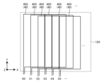
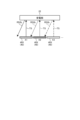
- FIGS. 2A and 2B are schematic diagrams of an example of the arrangement of the sensing coils 40.
- a plurality of detection coils 40 are arranged in a matrix in a direction that intersects with each other.
- FIG. 2A a plurality of charging devices 10 are arranged along the X-axis direction extending in the Y-axis direction and intersecting the Y-axis direction on a two-dimensional plane along the mounting surface 12A.
- a plurality of detection coils 40X are provided.
- FIG. 2A shows an example in which a plurality of sensing coils 40X are arranged at positions X0 to Xn (n is an integer of 1 or more) in the X-axis direction along the mounting surface 12A. show. These plurality of sensing coils 40X are arranged so that some regions in the arrangement direction (X-axis direction) overlap with each other.
- the charging device 10 includes a plurality of batteries extending in the X-axis direction on a two-dimensional plane along the mounting surface 12A and arranged along the Y-axis direction intersecting the X-axis direction.
- a detection coil 40Y is provided.
- FIG. 2B shows an example in which a plurality of sensing coils 40Y are arranged at positions Y0 to Yn (n is an integer of 1 or more) in the Y-axis direction along the mounting surface 12A. show. These plurality of sensing coils 40Y are arranged so that some regions in the arrangement direction (Y-axis direction) overlap with each other.
- FIGS. 2A and 2B show a plurality of sensing coils 40X and a plurality of sensing coils 40Y using separate drawings.
- a plurality of detection coils 40X and a plurality of detection coils 40Y are arranged to overlap in the Z-axis direction.
- the plurality of sensing coils 40 are shown as coils formed by one loop.
- each of the plurality of sensing coils 40 may be a coil consisting of two or more loops. The number of coil turns of the plurality of detection coils 40 may be adjusted in advance according to the target detection sensitivity.
- processing related to position identification is executed using a plurality of detection coils 40X and a plurality of detection coils 40Y arranged along each of the X-axis direction and the Y-axis direction. .
- the controller 50 executes information processing in the charging device 10.
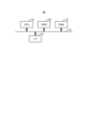
- FIG. 3 is a hardware configuration diagram of an example of the controller 50.
- the controller 50 has a hardware configuration using a normal computer, with a CPU (Central Processing Unit) 11A, a ROM (Read Only Memory) 11B, a RAM 11C, an I/F 11D, etc. connected to each other by a bus 11E. There is.
- a CPU Central Processing Unit
- ROM Read Only Memory
- RAM Random Access Memory
- I/F 11D I/F
- the CPU 11A is a calculation device that controls the charging device 10 of this embodiment.
- the ROM 11B stores programs and the like that implement various processes by the CPU 11A.
- the RAM 11C stores data necessary for various processing by the CPU 11A.
- the I/F 11D is an interface for transmitting and receiving data.
- a program for executing information processing executed by the charging device 10 of this embodiment is provided by being pre-installed in the ROM 11B or the like.
- the program executed by the charging device 10 of this embodiment is a file in a format that can be installed in the charging device 10 or an executable format, and can be stored on a CD-ROM, a flexible disk (FD), a CD-R, or a DVD (Digital Versatile). It may be configured to be recorded and provided on a computer-readable recording medium such as a computer-readable disk.
- Part or all of the controller 50 may be realized by having a processing device such as the CPU 11A execute a program, that is, by software, or may be realized by hardware such as an IC (Integrated Circuit). , may be realized using a combination of software and hardware.
- the controller 50 controls the power transmission coil 30, the plurality of detection coils 40, and the movement mechanism 36.
- the controller 50 selectively and sequentially outputs a transmission signal for generating a detection magnetic field to each of the plurality of detection coils 40, and in response to the detection magnetic field, the power receiving unit 22 outputs a transmission signal to each of the plurality of detection coils 40.
- the position of the power receiving unit 22 is specified based on the received signal detected in response to the .
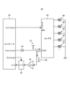
- FIG. 4 is a schematic diagram of an example of the circuit configuration of the charging device 10.
- FIG. 4 shows a circuit configuration portion related to position determination of the power receiving unit 22 in the charging device 10.
- the charging device 10 includes a controller 50, a plurality of detection coils 40, a selector 42, a diode 44, an amplifier 46, and a P/H 48.
- the controller 50 selectively outputs the transmission signal TS to a predetermined sensing coil 40 from the Echo_Pulse terminal via the diode 44 by switching the connection of the selector 42 via the Coil Select terminal.
- the transmission signal TS is a signal for generating a magnetic field for detection from the detection coil 40.
- the transmission signal TS is, for example, a pulse signal.
- the pulse width of the pulse signal is, for example, about 500 ns.
- the controller 50 responds to the detection magnetic field generated in the detection coil 40 by being supplied with the transmission signal TS, and transmits the received signal RS, which is responded from the power receiving section 22 of the terminal device 20 to the detection coil 40, to the selector 42. Detected through.
- the received signal RS is a signal sent in response from the power receiving unit 22 to the detection coil 40.
- the received signal RS is a signal representing a change in the magnetic field due to a back electromotive force that is responded from the power receiving unit 22 to the detection coil 40 immediately after the output of the transmitted signal TS, and is sometimes referred to as an echo signal.
- the controller 50 selectively detects the received signal RS responded to a predetermined detection coil 40 by switching the connection of the selector 42 via the Coil Select terminal.
- the received signal RS sent in response to the detection coil 40 is held in the P/H 48 via the amplifier 46.
- the P/H48 is a Peak-Hold circuit.
- the received signal RS which is an echo signal, has a frequency of approximately 1 MHz. Therefore, the controller 50 cannot measure the instantaneous voltage of the received signal RS using low-speed A/D conversion. Therefore, it is necessary for the P/H 48 to hold the peak voltage of the received signal RS.
- the controller 50 sends Discharge, which is a signal for discharging the charge stored in the P/H 48 to GND, to the P/H 48 immediately before measuring the next received signal RS. Output to.
- the controller 50 measures the level of the received signal RS after A/D conversion by A/D converting the received signal RS responded to the detection coil 40 and held in the P/H 48 . That is, the controller 50 acquires the level of the received signal RS that is sensed in response to the sensing coil 40 from the power receiving unit 22 in response to the magnetic field caused by the transmitted signal TS output to the sensing coil 40.
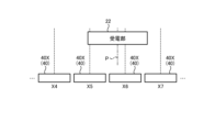
- FIG. 5 is a schematic diagram illustrating an example of the basic concept of specifying the position of the power receiving unit 22 by the controller 50.
- FIG. 5 shows, as an example, a plurality of sensing coils 40X arranged in the X-axis direction. Note that the same applies to the plurality of sensing coils 40Y arranged in the Y-axis direction.
- the controller 50 selectively and sequentially transmits data to each of the plurality of sensing coils 40 arranged at different positions such as X0, X1, X2, . . . in a time-sharing manner.
- a detection magnetic field is generated from the detection coil 40X in response to the transmission signal TS, and a reception signal RS is generated from the power reception unit 22 in response to the magnetic field.
- the controller 50 measures the level of the received signal RS detected by the detection coil 40 that is the output source of the transmitted signal TS.
- FIG. 6 is a schematic diagram showing an example of a timing chart regarding measurement of the level of the received signal RS.
- FIG. 6 shows a case where a transmission signal TS is output to the detection coil 40 and the level of the reception signal RS detected by the detection coil 40 from which the transmission signal TS is output is measured as a response to the magnetic field generated by the transmission signal TS.
- An example of a timing chart is shown below.
- the controller 50 switches the connection of the selector 42 via the Coil Select terminal, thereby bringing the sensing coil 40 at the n position and the controller 50 into a communicably connected state. Then, the controller 50 outputs a transmission signal TS to the detection coil 40 at the n position (see signal waveform 60A), and the COM terminal of the selector 42 outputs the transmission signal TS to the detection coil 40 at the n position in response to the transmission signal TS.
- the detected transmission signal TS and reception signal RS are output to the controller 50 (see signal waveform 60B).
- the controller 50 resets the previous measured value by outputting Discharge to the P/H 48 at the timing when the transmission signal TS is output (see signal waveform 60D).
- the controller 50 measures the level of the received signal RS after A/D conversion (signal waveform 60C).
- the controller 50 outputs the transmission signal TS to one of the plurality of sensing coils 40.
- a current flows through the detection coil 40, and a magnetic force is generated by the current.
- the lines of magnetic force due to the generated magnetic force penetrate the power receiving section 22 of the terminal device 20
- a current flows through the power receiving section 22 due to the back electromotive force.
- magnetic force is generated by the current flowing through the power receiving unit 22, and the lines of magnetic force penetrate the detection coil 40. Therefore, an electromotive force is generated in the detection coil 40, which is amplified by the amplifier 46, converted to a constant voltage via the P/H 48, and read by the A/D of the controller 50.
- the controller 50 stores the level of the received signal RS sent to the sensing coil 40. Then, the controller 50 sequentially performs these series of operations on each of the plurality of detection coils 40 provided in the charging device 10, and detects that the terminal device 20 is placed on the placement surface 12A. Repeat until. For example, the controller 50 determines that the terminal device 20 is placed on the placement surface 12A when any level of the received signal RS becomes equal to or higher than a certain voltage.
- the controller 50 determines whether the power receiving unit 22 of the terminal device 20 is activated based on the level of the reception signal RS received by each of the plurality of sensing coils 40. Locate.
- the controller 50 determines the position of the sensing coil 40 that has detected the maximum level of the received signal RS, the maximum level, the position of the other sensing coil 40 adjacent to the sensing coil 40, and the position of the other sensing coil 40 adjacent to the sensing coil 40.
- the position of the power receiving unit 22 is specified using the level of the received signal RS detected by the power receiving unit 22.
- the controller 50 determines the position of the sensing coil 40 that has detected the maximum level of the received signal RS, the position of the other sensing coil 40 adjacent to the sensing coil 40, and the position of the sensing coil 40 that has detected the maximum level and the other adjacent sensing coil RS.
- the position of the power receiving unit 22 is specified using the ratio with the level of the received signal RS detected by the coil 40.
- the controller 50 defines the position of the sensing coil 40X with the maximum level of the received signal RS among the plurality of sensing coils 40X arranged in the X-axis direction as X1st, and defines the maximum level as L1st. . Further, the controller 50 determines the position of one of the detection coils 40X, which has the highest level of the received signal RS, among the detection coils 40X arranged on both sides of the detection coil 40X in the X-axis direction with respect to the detection coil 40X with the highest level of the received signal RS. Let X2nd be the level, and define the level as L2nd. Further, the controller 50 sets the position of the other sensing coil 40X, which has the lower level of the received signal RS, among the sensing coils 40X arranged on both sides, to be X3rd, and defines this level as L3rd.
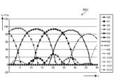
- FIGS. 7A and 7B are explanatory diagrams of an example of specifying the position of the power receiving unit 22 by basic position specifying processing of the power receiving unit 22 based on the received signal RS.
- FIG. 7A shows how the terminal device 20 placed on the mounting surface 12A is moved in the X-axis direction by 1 mm, and when the terminal device 20 is present at each position, a plurality of detections arranged along the X-axis direction are detected.
- FIG. 4 is a schematic diagram showing an example of the measurement results of the level of the received signal RS measured by each of the coils 40X.
- the horizontal axis represents the position of the power receiving unit 22 of the terminal device 20, and the vertical axis represents the measured level of the received signal RS.
- X0 to X13 represent the levels of the received signal RS detected by the detection coils 40X arranged at positions X0 to X13, respectively.
- FIG. 7A a scene is assumed in which the terminal device 20 is placed at a position PR 24 mm from the reference position in the X-axis direction.
- the level of the received signal RS detected by the detection coil 40X at position X6 is the highest.
- the level of the received signal RS detected by the detection coil 40X at position X5 is the second highest, and the level of the received signal RS detected by the detection coil 40X at position X7 is the third highest.
- the controller 50 specifies the position between the positions X6 and X5 as the position P of the power receiving unit 22 based on the ratio of the levels of the received signals RS detected by the detection coils 40X (see FIG. 7B). Similarly, by specifying the position in the Y-axis direction, the controller 50 specifies the position coordinates of the positions of the power receiving unit 22 in the X-axis direction and the Y-axis direction as the position P of the power receiving unit 22. .
- the present inventors found that with a method of specifying the position of the power receiving unit 22 without considering the relative distance, it may be difficult to specify the position P of the power receiving unit 22 with high accuracy. Ta.
- each of the plurality of detection coils 40 detects a signal based on the relative distance between the position of the power receiving unit 22 placed on the mounting surface 12A and the position of the power transmitting coil 30. It has been found that a change occurs in the level of the received signal RS. That is, the present inventors discovered that even if the received signal RS is detected by the same detection coil 40, the level of the received signal RS may vary depending on the relative distance between the power receiving section 22 and the power transmitting coil 30 at the time of detecting the received signal RS. We found that there may be differences. Further, the present inventors have found that the magnetic sheet 32 influences the difference in the level of the received signal RS depending on the relative distance.
- FIGS. 8A and 8B are explanatory diagrams of an example of the relationship between the relative distance between the power receiving unit 22 of the terminal device 20 and the power transmitting coil 30 and the level of the received signal RS.
- FIG. 8A is an explanatory diagram of an example of the level of the received signal RS when the power receiving unit 22 and the power transmitting coil 30 are located apart, that is, when the relative distance is large.
- the detection sensitivity of the reception signal RS of the sensing coil 40 by the magnetic sheet 32 increases or decreases, for example, by changing the sensitivity slope as shown in the diagram 62A. Become what you have. Specifically, due to the influence of the magnetic sheet 32 provided on the back side of the power transmitting coil 30, the L value of the sensing coil 40 located on the magnetic sheet 32 increases, and the output from the sensing coil 40 increases. The magnitude of the magnetic flux increases.
- the detection sensitivity of each received signal RS of the group of sensing coils 40 that detects the maximum and sub-maximum level received signals RS is , as shown in the diagram 62A, a sensitivity slope according to the relative distance is included.
- the sensitivity distribution of the received signal RS is as shown in the diagram 62B. As shown in the diagram 62B, the sensitivity of the received signal RS is maximum at the center position of the power receiving unit 22 of the terminal device 20, and the sensitivity of the received signal RS decreases as the distance from the center position increases.
- the level of the received signal RS detected by the detection coil 40X located at the position Xn corresponding to the center position of the power receiving unit 22 becomes maximum. Furthermore, the level of the received signal RS detected by the detection coil 40X placed at each of the positions Xn-1 and Xn+1 adjacent to Xn is lower than the maximum level.
- the detection sensitivity of each received signal RS of the group of detection coils 40 that detects each received signal RS at the maximum and near-maximum levels is includes a sensitivity slope depending on the relative distance, as shown in the diagram 62A. That is, when the power receiving unit 22 of the terminal device 20 is located at a position where the detection sensitivity of the received signal RS is inclined due to the influence of the magnetic sheet 32, a change occurs in the level of the detected received signal RS.
- the detection coils 40X placed at each of the positions Xn-1 and Xn+1 detect received signals RS at approximately the same level when not affected by the magnetic sheet 32.
- the detection sensitivity of the sensing coil 40 located closer to the power transmitting coil 30 and the magnetic sheet 32 is high, and the detection sensitivity of the sensing coil 40 located further from the power transmitting coil 30 and the magnetic sheet 32 is high. becomes lower. Therefore, compared to the level of the received signal RS detected by the detection coil 40X placed at position Xn-1, which is closer to the magnetic sheet 32, of the detection coils 40X placed at positions Xn-1 and Xn+1, respectively. Therefore, the level of the received signal RS detected by the detection coil 40X located at the position Xn+1 farther from the magnetic sheet 32 becomes lower.
- the position of the power receiving unit 22 is specified using the levels of these received signals RS without considering the relative distance, there will be a discrepancy between the specified position P and the actual position PR of the power receiving unit 22. G occurs. That is, if the power receiving unit 22 of the terminal device 20 is located at a position where the detection sensitivity of the received signal RS is inclined due to the influence of the magnetic sheet 32, the accuracy of identifying the position P of the power receiving unit 22 may decrease.
- FIG. 8B is an explanatory diagram of an example of the level of the received signal RS when the power receiving unit 22 and the power transmitting coil 30 are at approximately the same position, that is, when the relative distance is small.
- substantially the same position means that the positions in the two-dimensional plane along the mounting surface 12A are substantially the same.
- the increase or decrease in the detection sensitivity of the reception signal RS of the sensing coil 40 by the magnetic sheet 32 is as shown in the diagram 64A, for example.
- the detection sensitivity of each received signal RS of the group of detection coils 40 that detects each received signal RS at the maximum and near-maximum levels. are substantially the same, that is, are in a flat state, as shown in diagram 64A.
- the sensitivity distribution of the received signal RS is as shown in the diagram 64B.
- the sensitivity of the received signal RS is maximum at the center position of the power receiving unit 22 of the terminal device 20, and the sensitivity of the received signal RS decreases as the distance from the center position increases.
- the level of the received signal RS detected by the detection coil 40X located at the position Xn corresponding to the center position of the power receiving unit 22 becomes maximum. Furthermore, the level of the received signal RS detected by the detection coil 40X placed at each of the positions Xn-1 and Xn+1 adjacent to Xn is lower than the maximum level.
- each received signal RS of the group of detection coils 40 that detects each received signal RS at the maximum and near-maximum levels.
- the detection sensitivities of are approximately the same, that is, are in a flat state.
- the power receiving section 22 and the power transmitting coil 30 are located at approximately the same position, the influence of the magnetic sheet 32 is suppressed, and the position of the power receiving section 22 is determined using the highly accurately detected reception signal RS. can be specified. Therefore, it is considered that the accuracy of identifying the position P of the power receiving unit 22 is improved.
- the controller 50 controls the power receiving unit 22 according to the relative distance between the first position of the power receiving unit 22, which is the position specified based on the received signal RS, and the power transmitting coil 30.
- the position P of is specified.
- FIG. 9 is a flowchart showing an example of the flow of information processing executed by the controller 50 of this embodiment.
- the controller 50 initializes the position of the power transmission coil 30 (step S100).
- the controller 50 controls the moving mechanism 36 to move the power transmitting coil 30 held on the carrier 34 provided with the moving mechanism 36 to a predetermined initial position on the mounting surface 12A.
- the initial position is, for example, a position corresponding to the origin of each of the X-axis direction and the Y-axis direction of the mounting surface 12A, which is a two-dimensional plane. Through this movement control, the controller 50 initializes the position of the power transmission coil 30.
- the controller 50 determines whether the terminal device 20 is placed on the placement surface 12A (step S102).
- the controller 50 makes the determination in step S102 by measuring the generated magnetic field.
- the controller 50 makes the determination in step S102 by determining whether or not the level of the received signal RS detected by at least one of the plurality of sensing coils 40 has changed by a level equal to or higher than a threshold value. conduct.
- the controller 50 repeats the negative determination (step S102: No) until it makes an affirmative determination in step S102 (step S102: Yes).
- the process proceeds to step S104.
- step S104 the controller 50 identifies the first position P1 of the power receiving unit 22 (step S104).
- the first position P1 means the position P of the power receiving unit 22 specified based on the received signal RS detected in response to the transmitted signal TS outputted when the power transmitting coil 30 is in the initial position.
- the controller 50 selectively sequentially outputs the transmission signal TS to each of the plurality of sensing coils 40. Then, the controller 50 detects the level of the received signal RS that is detected in response to the detection magnetic field from the power receiving unit 22 to the detection coil 40 that is the output source of the transmitted signal TS. Then, the controller 50 specifies the position P of the power receiving unit 22 based on the level of the received signal RS detected by each of the plurality of detection coils 40 through the basic position specifying process using the above-mentioned ratio. The position P is specified as the first position P1.
- the controller 50 calculates the relative distance between the first position P1 identified in step S104 and the position of the power transmission coil 30 (step S106). For example, the controller 50 stores in advance initial position information representing the initial position for controlling the movement of the power transmitting coil 30 in step S100. Then, the controller 50 calculates the relative distance by calculating the distance between the first position P1 specified in step S104 and the initial position represented by the initial position information.
- controller 50 determines whether the relative distance calculated in step S106 is outside the predetermined distance range.
- the range of the predetermined distance may be determined in advance.
- the range of the predetermined distance may be set in advance as a range in which it can be determined that the power receiving section 22 and the power transmitting coil 30 are at substantially the same position in a two-dimensional plane along the mounting surface 12A.
- the increase or decrease in the detection sensitivity of the received signal RS of the sensing coil 40 due to the influence of the magnetic sheet 32 explained using the diagram 62A of FIG. 8A and the diagram 64A of FIG. 8B is the maximum and It is sufficient to set in advance a range of relative distances that are approximately the same, that is, a flat state, at each position of the group of sensing coils 40 that detect each received signal RS at a level close to the maximum level.
- step S106 If the relative distance calculated in step S106 is within the predetermined distance range (step S108: No), the controller 50 starts charging control from the power transmitting coil 30 to the power receiving unit 22 (step S110).
- the controller 50 applies AC power to the power transmission coil 30, communicates with the terminal device 20 via the power transmission coil 30, and controls the power to be supplied in response to a power request command from the terminal device 20. do.
- the controller 50 includes a circuit for performing bidirectional communication with the terminal device 20, and communicates with the terminal device 20 using the circuit.
- the power transmitting coil 30 is electromagnetically coupled to the power receiving unit 22 of the terminal device 20 to supply AC power to the power receiving unit 22 .
- the AC power supplied to the power receiving unit 22 is converted into DC power by a rectifier provided in the terminal device 20, and the battery 24 is charged. Therefore, the battery 24 of the terminal device 20 is wirelessly charged. Then, this routine ends.
- step S106 determines whether the relative distance calculated in step S106 is outside the predetermined distance range. If the relative distance calculated in step S106 is outside the predetermined distance range (step S108: Yes), the controller 50 proceeds to step S112.
- step S112 the controller 50 specifies the position of the power receiving unit 22 of the terminal device 20 by executing a unique position specifying process (step S112). Then, the controller 50 starts charging control in the same manner as in step S110 (step S114), and ends this routine.
- step S112 The specific position specifying process in step S112 will be explained in detail.
- the controller 50 When the relative distance between the first position of the power receiving unit 22 and the power transmitting coil 30 is outside the predetermined distance range, the controller 50 performs a first position specifying process, a second position specifying process, a third position specifying process, and a fourth position specifying process.
- the controller 50 executes the following process as the first position specifying process. Specifically, when the relative distance is outside the predetermined distance range, the controller 50 controls the movement of the power transmission coil 30 to the first position P1. Then, the controller 50 moves the power receiving unit 22 to a second position P2, which is the position of the power receiving unit 22, which is specified based on the received signal RS detected in response to the transmitted signal TS output while the power transmitting coil 30 is present at the first position P1. is specified as the position P of the power receiving unit 22.
- the second position P2 means the position P of the power receiving unit 22, which is specified based on the received signal RS detected in response to the transmitted signal TS outputted while the power transmitting coil 30 is in the first position P1. do.
- the power transmitting coil 30 is controlled to move to the first position P1, which is tentatively identified as the position P of the power receiving unit 22, and the transmitting signal output while the power transmitting coil 30 is present at the first position P1 is controlled.
- the second position P2 specified based on the received signal RS detected in response to the TS is specified as the official position P of the power receiving unit 22.
- FIG. 10 is a flowchart illustrating an example of the flow of the first position specifying process executed by the controller 50.
- the controller 50 controls the movement of the power transmission coil 30 to the first position P1 specified in step S104 (see FIG. 9) (step S200). Specifically, the controller 50 controls the moving mechanism 36 to move to the first position P1. The moving mechanism 36 moves the carrier 34 to the first position P1 under the control of the controller 50, so that the power transmission coil 30 placed on the carrier 34 moves to the first position P1.
- the controller 50 identifies the second position P2 of the power receiving unit 22 (step S202). For example, the controller 50 selectively sequentially outputs the transmission signal TS to each of the plurality of sensing coils 40. Then, the controller 50 detects the level of the received signal RS that is detected in response to the detection magnetic field from the power receiving unit 22 to the detection coil 40 that is the output source of the transmitted signal TS. Then, the controller 50 specifies the position P of the power receiving unit 22 based on the level of the received signal RS detected by each of the plurality of sensing coils 40 through the basic position specifying process using the ratio described above. 2. Identify position P2.
- the controller 50 controls the movement of the power transmission coil 30 to the second position P2 specified in step S202 (step S204). Specifically, the controller 50 controls the moving mechanism 36 to move to the second position P2. The moving mechanism 36 moves the carrier 34 to the second position P2 under the control of the controller 50, so that the power transmission coil 30 placed on the carrier 34 moves to the second position P2. Then, this routine ends.
- controller 50 executes the first position specifying process shown in FIG. 10 as the position specifying process in step S112 shown in FIG. Control begins.
- FIGS. 11A and 11B are explanatory diagrams of an example of the effect of the first position specifying process.
- the horizontal axis indicates the position in the X-axis direction on the mounting surface 12A.
- the vertical axis represents the level of the received signal RS.
- X0, X1, and X2 represent the levels of the received signal RS detected by the detection coils 40X arranged at the respective positions X0, X1, and X2, respectively.
- FIG. 11A is an explanatory diagram of the received signal RS detected by each of the detection coils 40 that detected the received signal RS used to identify the first position P1.
- the power transmitting coil 30 is located at position X0
- the power receiving unit 22 is located at a position "14 mm" from the origin in the X-axis direction, which is between positions Suppose.
- the received signal RS detected by the detection coil 40X placed at each of the positions X0, X1, and X2 is as shown in FIG. 11A. That is, as explained using FIG. 8A above, the received signal RS includes a sensitivity gradient due to the influence of the magnetic sheet 32. Therefore, the first position P1 of the power receiving unit 22 identified using the levels of these received signals RS is, for example, "16 mm" from the origin, which is an intermediate position between the positions X1 and X2, and is different from the actual position. A deviation of 2 mm occurs.
- FIG. 11B is an explanatory diagram of the received signal RS detected by each of the detection coils 40 that detected the received signal RS used to specify the second position P2.
- the power transmitting coil 30 is located at the first position P1
- the power receiving unit 22 is located at a position "14 mm" from the origin in the X-axis direction, which is between positions X2 and X3, as in FIG. 11A.
- the received signal RS detected by the detection coil 40X arranged at each of the positions X0, X1, and X2 is as shown in FIG. 11B. That is, as explained using FIG. 8B above, the received signal RS does not include the sensitivity gradient due to the influence of the magnetic sheet 32. Therefore, the second position P2 of the power receiving unit 22 identified using the levels of these received signals RS is a position "14 mm" from the origin, which is an intermediate position between the positions X1 and X2, which is the actual position. 14 mm” is specified as the official position P of the power receiving unit 22.
- the controller 50 controls the movement of the power transmitting coil 30 to the first position P1, which is tentatively specified as the position P of the power receiving unit 22. Then, the controller 50 moves the second position P2, which is specified based on the received signal RS detected in response to the transmitted signal TS output while the power transmitting coil 30 is present at the first position P1, to the official position of the power receiving unit 22. It is specified as a position P.
- the controller 50 uses the sensitivity of the magnetic sheet 32.
- the second position P2 can be specified while the influence of inclination is suppressed. Therefore, by executing the first position specifying process, the controller 50 determines the position P of the power receiving unit 22 of the terminal device 20, compared to the case where the first position P1 is specified as the official position P of the power receiving unit 22. It can be specified with high precision.
- the controller 50 executes the following process as the second position specifying process. Specifically, when the relative distance is outside the predetermined distance range, the controller 50 controls the movement of the power transmitting coil 30 to the first position P1, and then starts charging control from the power transmitting coil 30 to the power receiving unit 22. Then, if the terminal device 20 that started the charging control is a predetermined terminal device, the controller 50 stops the charging control. Then, the controller 50 moves the position P of the power receiving unit 22, identified based on the received signal RS detected in response to the transmitted signal TS output while the power transmitting coil 30 is present at the first position P1, to the second position. Specify as P2. Then, the controller 50 specifies the specified second position P2 as the official position P of the power receiving unit 22.
- the predetermined terminal device may be a predetermined terminal device 20.
- the predetermined terminal device is a magnet-equipped terminal device in which a magnet is disposed on at least a portion of the outer periphery of the power receiving unit 22 .
- a terminal device with a magnet is sometimes referred to as an MPP (Magnetic Power Profile) terminal.
- the controller 50 After controlling the movement of the power transmitting coil 30 to the first position P1, the controller 50 starts charging control of the power of the first frequency from the power transmitting coil 30 to the power receiving unit 22. Then, after controlling the movement of the power transmitting coil 30 to the second position P2, the controller 50 may start charging control of power having a second frequency higher than the first frequency from the power transmitting coil 30 to the power receiving unit 22. That is, when the terminal device 20 is a predetermined terminal device such as a terminal device with a magnet, the controller 50 performs power reception control using the power of the first frequency when the power transmission coil 30 is located at the first position P1, and performs more accurate power reception control. When the power transmission coil 30 is located at the second position P2, rapid charging may be performed using power at a second frequency higher than the first frequency.
- FIG. 12 is a flowchart illustrating an example of the flow of the second position specifying process executed by the controller 50.
- the controller 50 controls the movement of the power transmission coil 30 to the first position P1 specified in step S104 (see FIG. 9) (step S300). Specifically, the controller 50 controls the moving mechanism 36 to move to the first position P1. The moving mechanism 36 moves the carrier 34 to the first position P1 under the control of the controller 50, so that the power transmission coil 30 placed on the carrier 34 moves to the first position P1.
- the controller 50 sets the charging frequency to the first frequency (step S302).
- the first frequency is, for example, 128 kHz, but is not limited to this value.
- the controller 50 applies the AC voltage of the first frequency set in step S302 to the power transmitting coil 30, and starts charging control from the power transmitting coil 30 to the power receiving unit 22 (step S304).
- the controller 50 determines whether the terminal device 20 equipped with the power receiving unit 22 that started charging in step S304 is a predetermined terminal device (step S306).
- the controller 50 performs the determination in step S306 by communicating with the terminal device 20 via the power transmission coil 30 and receiving information indicating whether or not the terminal device 20 is a predetermined terminal device from the terminal device 20. do it.
- step S306 determines that it is not the predetermined terminal device (step S306: No). Therefore, when the controller 50 makes a negative determination in step S306, the controller 50 continues the charging control started in step S304. On the other hand, if the controller 50 determines that the terminal device is the predetermined terminal device (step S306: Yes), the process proceeds to step S308.
- step S308 the controller 50 stops the charging control started in step S304 (step S308), and proceeds to step S310.
- the controller 50 may communicate with the terminal device 20 via the power transmission coil 30 and further determine whether or not a signal representing a charging frequency change instruction has been received from the terminal device 20. If the controller 50 does not receive a signal representing a charging frequency change instruction, the controller 50 may continue the charging control started in step S304 without stopping the charging control, and may end this routine. On the other hand, when the controller 50 receives a signal representing a charging frequency change instruction, it may execute the process of step S308.
- step S310 the controller 50 identifies the second position P2 of the power receiving unit 22 (step S310). Then, the controller 50 controls the movement of the power transmission coil 30 to the second position P2 specified in step S310 (step S312).
- step S310 and step S312 are the same as those in step S202 and step S204, respectively.
- the controller 50 sets the charging frequency to the second frequency (step S314).
- the second frequency may be a higher frequency than the first frequency.
- the second frequency is, for example, 360 kHz, but is not limited to this value. Then, this routine ends.
- the controller 50 executes the second position specifying process shown in FIG. 12 as the position specifying process in step S112 shown in FIG. Rapid charging control is started.
- the power transmitting coil 30 is controlled to move to the first position P1, which is tentatively specified as the position P of the power receiving unit 22.
- the received signal RS detected in response to the transmitted signal TS output while the power transmitting coil 30 is present at the first position P1 is The second position P2 specified based on the second position P2 is specified as the official position P of the power receiving unit 22.
- charging control of the power of the first frequency is started by the power transmitting coil 30 existing at the first position P1, and if the terminal device 20 is a predetermined terminal device, the power transmitting coil 30 is controlled more accurately. In the state in which the battery is moved to the second position P2, which is the position P, charging control of the power of the second frequency is further started.
- the second position P2 is specified based on the received signal RS detected in response to the transmitted signal TS output while the power transmitting coil 30 is present at the first position P1. Therefore, the controller 50 can specify the second position P2 while the influence of sensitivity fluctuations caused by the magnetic sheet 32 is suppressed. That is, by executing the second position specifying process, the controller 50 can determine the position of the power receiving unit 22 of the terminal device 20 with higher accuracy than when specifying the first position P1 as the official position P of the power receiving unit 22. can be specified.
- the controller 50 can perform rapid charging after aligning the position of the power transmission coil 30 with respect to a predetermined terminal device with high precision.
- the controller 50 executes the following process as the third position specifying process. Specifically, when the relative distance is outside the predetermined distance range, the controller 50 corrects the received signal RS used to specify the first position P1 with a correction coefficient Ke corresponding to the relative distance. , the position of the power receiving unit 22 is specified.
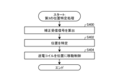
- FIG. 13A is a flowchart illustrating an example of the flow of the third position specifying process executed by the controller 50.
- the controller 50 corrected the received signal RS used to specify the first position P1 specified in step S104 (see FIG. 9) with a correction coefficient Ke according to the relative distance between the first position P1 and the power transmission coil 30.
- a corrected received signal is calculated (step S400).
- the controller 50 acquires the level of the received signal RS used to specify the first position P1 specified in step S104 (see FIG. 9). For example, the controller 50 obtains the above-mentioned level L1st, level L2nd, and level L3rd of the received signal RS as the levels of the plurality of received signals RS used to specify the first position P1.
- the controller 50 specifies a correction coefficient Ke according to the relative distance between the first position P1 and the power transmission coil 30.
- the correction coefficient ke is a coefficient for canceling the sensitivity gradient due to the magnetic sheet 32 included in the received signal RS.
- FIG. 13B is an explanatory diagram of the correction coefficient Ke.
- the horizontal axis represents the relative distance
- the vertical axis represents the correction coefficient Ke.
- the correction coefficient Ke represents a value smaller than 1 when the relative distance is short, that is, when the power receiving unit 22 and the power transmitting coil 30 are close to each other.
- the correction coefficient Ke represents a value larger than 1 when the relative distance is long, that is, the positions of the power receiving unit 22 and the power transmitting coil 30 are far.
- the controller 50 stores in advance relational information or a function shown in FIG. 13B representing the relationship between the correction coefficient Ke according to the relative distance between the first position P1 and the power transmitting coil 30. Then, the controller 50 may specify the correction coefficient Ke corresponding to the relative distance between the first position P1 and the power transmitting coil 30 from the above relationship information or function.
- the controller 50 multiplies each of the levels L1st, L2nd, and L3rd of the plurality of received signals RS used to specify the first position P1 by the specified correction coefficient Ke.
- the controller 50 calculates each of the corrected level L1st', level L2nd', and level L3rd', which are the results of this multiplication processing, as a corrected received signal for each of the plurality of received signals RS.
- the correction coefficient Ke is a coefficient for canceling the sensitivity gradient due to the magnetic sheet 32 included in the received signal RS. Therefore, the corrected level L1st', level L2nd', and level L3rd', which are the corrected reception signals, are levels at which the influence of the sensitivity gradient due to the magnetic sheet 32 is canceled out.
- the controller 50 identifies the position P of the power receiving unit 22 using the corrected reception signal calculated in step S400 (step S402). That is, the controller 50 re-specifies the position P of the power receiving unit 22 using a corrected received signal obtained by correcting the received signal RS used to specify the first position P1.
- the controller 50 specifies the first position P1 in step S104, except that the corrected level L1st', level L2nd', and level L3rd' are used in place of each of the level L1st, level L2nd, and level L3rd.
- the position P of the power receiving unit 22 may be specified by a process similar to the process described above.
- the controller 50 controls the movement of the power transmission coil 30 to the position P specified in step S402 (step S404). Specifically, the controller 50 controls the moving mechanism 36 to move to the position P specified in step S402. The moving mechanism 36 moves the conveyance table 34 to the position P under the control of the controller 50, so that the power transmission coil 30 placed on the conveyance table 34 moves to the position P. Then, this routine ends.
- controller 50 executes the third position specifying process shown in FIG. 13A as the position specifying process in step S112 shown in FIG. 22 is started.
- the controller 50 corrects the received signal RS used to specify the first position P1, which is tentatively specified as the position P of the power receiving unit 22, with the correction coefficient Ke according to the relative distance.
- the position P of the power receiving unit 22 is specified based on the corrected received signal.
- the controller 50 specifies the position P of the power receiving unit 22 specified based on the corrected reception signal as the official position P of the power receiving unit 22.
- the controller 50 specifies the position P of the power receiving unit 22 using the corrected reception signal in which the influence of the sensitivity gradient due to the magnetic sheet 32 has been canceled. Therefore, the controller 50 can specify the position of the power receiving unit 22 of the terminal device 20 with high accuracy.
- the controller 50 executes the following process as the fourth position specifying process. Specifically, when the relative distance is outside the predetermined distance range, the controller 50 identifies the position P of the power receiving unit 22 based on the third position P3 and the fourth position P4.
- the third position P3 is the reception signal RS detected by each of the plurality of detection coils 40 from which the transmission signal TS is output, in response to the transmission signal TS sequentially output to each of the plurality of detection coils 40. This is the position P specified based on the first received signal RS1.
- the first received signal RS1 is an example of the received signal RS.
- the fourth position P4 refers to a received signal detected by each of the plurality of detection coils 40 other than the output source of the transmission signal TS in response to the transmission signal TS sequentially output to each of the plurality of detection coils 40. This is the position P specified based on the second received signal RS2 which is RS.
- the second received signal RS2 is an example of the received signal RS.
- FIGS. 14A to 14C are explanatory diagrams of an example of the fourth position specifying process.
- the controller 50 selectively and sequentially sends a transmission signal TS to each of the plurality of sensing coils 40 arranged at different positions such as X1, X2, X3, . Output. Then, the controller 50 measures the level of the first received signal RS1, which is the received signal RS detected by the detection coil 40 that is the output source of the transmitted signal TS. Then, the controller 50 specifies the third position P3 of the power receiving unit 22 by specifying the position P of the power receiving unit 22 based on the first received signal RS1 through the basic position specifying process using the ratio described above. .
- the controller 50 selectively and sequentially transmits data to each of the plurality of sensing coils 40 arranged at different positions such as X1, X2, X3, . . . Outputs signal TS. Then, the controller 50 measures the level of the second reception signal RS2a, which is the reception signal RS detected by the detection coil 40 other than the output source of the transmission signal TS.
- the second received signal RS2a is an example of the second received signal RS2.
- FIG. 14B shows, as the second received signal RS2a, a second received signal RS2a detected by another sensing coil 40 next to the sensing coil 40 that is the output source of the transmission signal TS.
- the controller 50 specifies the fourth position P4a of the power receiving section 22 by specifying the position P of the power receiving section 22 based on the second received signal RS2a by the basic position specifying process using the ratio described above.
- the fourth position P4a is an example of the fourth position P4.
- the controller 50 selectively and sequentially transmits data to each of the plurality of sensing coils 40 arranged at different positions such as X1, X2, X3, . . . Outputs signal TS. Then, the controller 50 measures the level of the second reception signal RS2b, which is the reception signal RS detected by the detection coil 40 other than the output source of the transmission signal TS.
- the second received signal RS2b is an example of the second received signal RS2.
- FIG. 14C shows, as the second received signal RS2b, the second received signal RS2b detected by another sensing coil 40 immediately preceding the sensing coil 40 that is the output source of the transmission signal TS.
- the controller 50 specifies the fourth position P4b of the power receiving section 22 by specifying the position P of the power receiving section 22 based on the second received signal RS2b by the basic position specifying process using the ratio described above.
- the fourth position P4b is an example of the fourth position P4.
- FIG. 15 is a schematic diagram showing an example of a timing chart regarding measurement of the level of the second received signal RS2.
- FIG. 15 shows an example of a timing chart when outputting the transmission signal TS to the detection coil 40 and measuring the level of each of the first reception signal RS1, the second reception signal RS2a, and the second reception signal RS2b. show.
- the controller 50 switches the connection of the selector 42 via the Coil Select terminal, thereby bringing the sensing coil 40 at the n position and the controller 50 into a communicably connected state. Then, the controller 50 outputs a transmission signal TS to the detection coil 40 at the n position (see signal waveform 68A1), and the COM terminal of the selector 42 outputs the transmission signal TS to the detection coil 40 at the n position in response to the transmission signal TS.
- the detected transmission signal TS and reception signal RS are output to the controller 50 (see signal waveform 68B1).
- the controller 50 resets the previous measured value by outputting Discharge to the P/H 48 at the timing of outputting the transmission signal TS (see signal waveform 68D1).
- the controller 50 measures the level of the first received signal RS1 after A/D conversion by A/D converting the received signal RS responded to the detection coil 40 at the n position and held in the P/H 48 ( (See signal waveform 68C1).
- the controller 50 switches the connection of the selector 42 via the Coil Select terminal, thereby bringing the sensing coil 40 at the n position and the controller 50 into a communicably connected state.
- the controller 50 outputs the transmission signal TS to the detection coil 40 at the n position (see signal waveform 68A2)
- the connection of the selector 42 is switched via the Coil Select terminal to detect the n+1 position.
- the coil 40 and the controller 50 are in a connected state in which they are communicably connected.
- the COM terminal of the selector 42 outputs the transmission signal TS detected by the detection coil 40 at the n+1 position and the second reception signal RS2a of the detection coil 40 at the n+1 position to the controller 50 in response to the transmission signal TS.
- the controller 50 resets the previous measured value by outputting Discharge to the P/H 48 at the timing of outputting the transmission signal TS (see signal waveform 68D2).
- the controller 50 A/D converts the second received signal RS2a that is responded to the detection coil 40 at the n+1 position and is held in the P/H 48, thereby adjusting the level of the second received signal RS2a after A/D conversion. (See signal waveform 68C2).
- the controller 50 switches the connection of the selector 42 via the Coil Select terminal, thereby bringing the sensing coil 40 at the n position and the controller 50 into a communicably connected state.
- the controller 50 outputs the transmission signal TS to the detection coil 40 at the n position (see signal waveform 68A3), the connection of the selector 42 is switched via the Coil Select terminal to detect the n-1 position.
- the coil 40 and the controller 50 are in a connected state in which they are communicably connected.
- the COM terminal of the selector 42 sends the transmission signal TS detected by the detection coil 40 at the n-1 position and the second reception signal RS2b of the detection coil 40 at the n-1 position to the controller 50 in response to the transmission signal TS.
- the controller 50 resets the previous measured value by outputting Discharge to the P/H 48 at the timing of outputting the transmission signal TS (see signal waveform 68D3).
- the controller 50 A/D converts the second received signal RS2b that is responded to the detection coil 40 at the n-1 position and is held in the P/H 48, thereby adjusting the level of the second received signal RS2b after A/D conversion. (See signal waveform 68C3).
- 16A to 16C show the respective positions of the third position P3, the fourth position P4a, and the fourth position P4b specified from the first received signal RS1, the second received signal RS2a, and the second received signal RS2b, respectively. It is an explanatory view of a specific example.
- the fourth position P4a and the fourth position P4b are examples of the fourth position P4.
- the horizontal axis indicates the position in the X-axis direction on the mounting surface 12A.
- the vertical axis represents the level of the received signal RS.
- X0 to X13 represent the levels of the received signal RS detected by the detection coils 40X arranged at the respective positions X0 to X13.
- the controller 50 specifies the position P of the power receiving unit 22 based on the first received signal RS1 shown in FIG. 16A through the basic position specifying process using the ratio described above, thereby specifying the position X1 as the third position P3.
- the controller 50 specifies the position P of the power receiving unit 22 based on the first received signal RS1 shown in FIG. 16A through the basic position specifying process using the ratio described above, thereby specifying the position X1 as the third position P3.
- the second received signal RS2a detected by each of the other sensing coils 40 next to the plurality of sensing coils 40 from which the transmitted signal TS is output is the received signal RS shown in FIG. 16B.
- the controller 50 specifies the position P of the power receiving unit 22 based on the second received signal RS2a shown in FIG. 16B through the basic position specifying process using the ratio described above, thereby specifying the position X2 as the fourth position P4a.
- the controller 50 specifies the position P of the power receiving unit 22 based on the second received signal RS2a shown in FIG. 16B through the basic position specifying process using the ratio described above, thereby specifying the position X2 as the fourth position P4a.
- the specific situation is the specific situation.
- the second received signal RS2b detected by each of the other sensing coils 40 immediately preceding the plurality of sensing coils 40 that are the output source of the transmitted signal TS was the received signal RS shown in FIG. 16C.
- the controller 50 specifies the position P of the power receiving unit 22 based on the second received signal RS2b shown in FIG. 16C through the basic position specifying process using the ratio described above, thereby specifying the position X3 as the fourth position P4b.
- the controller 50 specifies the position P of the power receiving unit 22 based on the second received signal RS2b shown in FIG. 16C through the basic position specifying process using the ratio described above, thereby specifying the position X3 as the fourth position P4b.
- the specific situation is the specific situation.
- the controller 50 specifies the accurate position P of the power receiving unit 22 based on the position X1 which is the third position P3, the position X2 which is the fourth position P4a, and the position X3 which is the fourth position P4b. .
- the controller 50 calculates the average position of the position X1 which is the third position P3, the position X2 which is the fourth position P4a, and the position X3 which is the fourth position P4b using the following formula (1).
- the controller 50 specifies the position X, which is the average position calculated by equation (1), as the accurate position P of the power receiving unit 22.
- controller 50 only needs to calculate the position P of the power receiving unit 22 based on the third position P3 and the fourth position P4, and is not limited to the form using the average position.
- the controller 50 specifies the average position calculated by weighting at least one of the third position P3 and the fourth position P4 according to the relative distance, etc., as the accurate position P of the power receiving unit 22. Good too.
- the controller 50 may calculate the position of the power receiving unit 22 based on the third position P3 and the fourth position P4, and the number of the fourth positions P4 can be divided into two types: the fourth position P4a and the fourth position P4b. It is not limited to , and may be one type or three or more types.
- the controller 50 sets the fourth position P4 to the n+1 position, that is, the second position detected by the next sensing coil 40 adjacent to the sensing coil 40 that is the output source of the transmission signal TS. Only the received signal RS2a may be used as the second received signal RS2. Then, the controller 50 may specify the position X, which is the average position of the third position P3 and the fourth position P4a, as the accurate position P of the power receiving unit 22.
- the controller 50 may use the second reception signal RS2, which is the reception signal RS detected by each of the plurality of detection coils 40 other than the output source of the transmission signal TS, and detects the output source of the transmission signal TS.
- the present invention is not limited to the form in which the received signal RS of another sensing coil 40 adjacent to the coil 40 is used.
- the controller 50 sets each of the two or more plurality of sensing coils 40 arranged in a direction away from the sensing coil 40 that is the output source of the transmission signal TS as the fourth position P4.
- the received signal RS detected in the above may be used as the second received signal RS.
- FIG. 17 is a flowchart illustrating an example of the flow of the fourth position specifying process executed by the controller 50.
- step S500 The controller 50 controls the movement of the power transmission coil 30 to the first position P1 specified in step S104 (see FIG. 9) (step S500).
- the process in step S500 is similar to step S200 above.
- the controller 50 identifies the third position P3 of the power receiving unit 22 (step S502). For example, the controller 50 selectively sequentially outputs the transmission signal TS to each of the plurality of sensing coils 40. Then, the controller 50 detects the level of the first reception signal RS1 that is detected in response to the detection magnetic field from the power receiving unit 22 to the detection coil 40 that is the output source of the transmission signal TS. Then, the controller 50 specifies the position P of the power receiving unit 22 based on the level of the first received signal RS1 detected by each of the plurality of detection coils 40 by the basic position specifying process using the ratio described above. , specifies the third position P3.
- the controller 50 identifies the fourth position P4a of the power receiving unit 22 (step S504). For example, the controller 50 selectively sequentially outputs the transmission signal TS to each of the plurality of sensing coils 40. Then, in response to the detection magnetic field, the controller 50 causes the power receiving unit 22 to respond to the next detection coil 40 adjacent to the detection coil 40 that is the output source of the transmission signal TS. 2 detect the level of the received signal RS2a. Then, the controller 50 specifies the position P of the power receiving unit 22 based on the level of the second reception signal RS2a detected by each of the plurality of detection coils 40 by the basic position specifying process using the ratio described above. , specifies the fourth position P4a.
- the controller 50 identifies the fourth position P4b of the power receiving unit 22 (step S506). For example, the controller 50 selectively sequentially outputs the transmission signal TS to each of the plurality of sensing coils 40. Then, in response to the detection magnetic field, the controller 50 causes the power receiving unit 22 to respond to the other detection coil 40 immediately preceding the detection coil 40 that is the output source of the transmission signal TS. 2 detect the level of the received signal RS2b. Then, the controller 50 specifies the position P of the power receiving unit 22 based on the level of the second reception signal RS2b detected by each of the plurality of detection coils 40 by the basic position specifying process using the ratio described above. , specifies the fourth position P4b.
- the controller 50 specifies the accurate position P of the power receiving unit 22 using the third position P3 specified in step S502, the fourth position P4a specified in step S504, and the fourth position P4b specified in step S506. (Step S508). For example, the controller 50 identifies the average position of the third position P3, the fourth position P4a, and the fourth position P4b as the accurate position P of the power receiving unit 22.
- step S510 the controller 50 controls the movement of the power transmission coil 30 to the position P specified in step S508 (step S510). Then, this routine ends.
- the controller 50 executes the fourth position specifying process shown in FIG. 17 as the position specifying process in step S112 shown in FIG. 30 starts charging control to the power receiving unit 22.
- FIGS. 18A to 18C are explanatory diagrams of an example of the effect of the fourth position specifying process.
- the horizontal axis indicates the position in the X-axis direction on the mounting surface 12A.
- the vertical axis represents the level of the received signal RS.
- X0, X1, and X2 represent the levels of the received signal RS detected by the detection coils 40X arranged at the respective positions X0, X1, and X2, respectively.
- 18A to 18C show a situation where the power receiving unit 22 of the terminal device 20 is placed at a position PR of "11 mm".
- FIG. 18A is an explanatory diagram of the first received signal RS1 detected by each of the detection coils 40 that detected the received signal RS used to specify the third position P3.
- FIG. 18B is an explanatory diagram of the second received signal RS2a detected by each of the detection coils 40 that detected the received signal RS used to specify the fourth position P4a.
- FIG. 18C is an explanatory diagram of the second received signal RS2b detected by each of the detection coils 40 that detected the received signal RS used to specify the fourth position P4b.
- the first reception signal RS1 received by the detection coil 40 placed near the position PR is An error occurs in the third position P3 calculated using the noise Z due to the influence of the noise Z.
- a fourth position P4a and a fourth position P4b are calculated using each of the second received signal RS2a and second received signal RS2b received by another sensing coil 40 different from the sensing coil 40 that outputs the transmission signal TS. does not include errors due to the influence of noise Z (see FIGS. 18B and 18C).
- the controller 50 can determine a more accurate position with reduced errors due to the influence of the noise Z. P can be specified. For example, when the controller 50 specifies the average position of the third position P3, the fourth position P4a, and the fourth position P4b as the position P of the power receiving unit 22, the controller 50 determines the position P where the influence of the noise Z is reduced to 1/3. can be specified.
- the fourth position specifying process is effective in reducing the influence of noise Z, and therefore, it is possible to more effectively and accurately locate the power receiving unit 22 for the terminal device 20 where noise Z is more likely to occur. It becomes possible to specify the location of
- the charging device 10 of the present embodiment wirelessly charges the terminal device 20 that is placed on the placement surface 12A and includes the power receiving section 22 that receives wirelessly transmitted power.
- the charging device 10 of this embodiment includes a power transmission coil 30, a plurality of detection coils 40, a movement mechanism 36, and a controller 50.
- the power transmission coil 30 transmits power to the terminal device 20.
- the plurality of detection coils 40 are coils for detecting the position of the power receiving section 22 of the terminal device 20 on the mounting surface 12A.
- the moving mechanism 36 moves the power transmission coil 30.
- the controller 50 controls the power transmission coil 30, the plurality of detection coils 40, and the movement mechanism 36.
- the controller 50 selectively and sequentially outputs a transmission signal TS for generating a detection magnetic field to each of the plurality of detection coils 40, and in response to the detection magnetic field, the power receiving unit 22 outputs a transmission signal TS to each of the plurality of detection coils 40.
- the position P of the power receiving unit 22 is specified based on the received signal RS detected in response to each.
- the controller 50 specifies the position P of the power receiving section 22 according to the relative distance between the power transmitting coil 30 and the first position P1 of the power receiving section 22, which is the position P specified based on the received signal RS.
- the controller 50 of the charging device 10 of the present embodiment sets the position P specified according to the relative distance between the first position P1 of the power receiving unit 22 specified based on the received signal RS and the power transmission coil 30 to receive power.
- the exact position P of the portion 22 is specified.
- the charging device 10 of the present embodiment has a high accuracy that suppresses the influence of the magnetic sheet 32, etc., compared to the case where the specified position P is specified as the accurate position P of the power receiving unit 22 regardless of the relative distance.
- the position P of the power receiving unit 22 can be specified.
- the charging device 10 of this embodiment can specify the position P of the power receiving unit 22 of the terminal device 20 with high accuracy.
- the controller 50 when the relative distance between the first position of the power receiving unit 22 and the power transmitting coil 30 is outside the predetermined distance range, the controller 50 performs the first position specifying process, the second position specifying process, The form in which the position specifying process, either the third position specifying process or the fourth position specifying process, is executed has been described.
- Which of these position specifying processes the controller 50 executes may be determined in advance. For example, the controller 50 executes a position specifying process preset by the user or the like among the first position specifying process, the second position specifying process, the third position specifying process, and the fourth position specifying process. Bye. Further, the information indicating which position specifying process is to be executed may be changeable as appropriate based on the user's operation instructions on the operation unit or the like.
- the controller 50 performs the first position specifying process, the second position specifying process, and the third position specifying process. Two or more of the identification process and the fourth location identification process may be executed in combination.
- controller 50 may execute the fourth position specifying process in combination with each of the first position specifying process, the second position specifying process, and the third position specifying process.
- the controller 50 detects the received The second position P2, which is the position of the power receiving unit 22 specified based on the signal RS, is specified as the official position P of the power receiving unit 22.
- the controller 50 may perform a fourth position specifying process in combination when specifying at least one of the first position P1 and the second position P2 in the first position specifying process and the second position specifying process. .
- the controller 50 specifies at least one of the first position P1 and the second position P2 based on the third position P3 and the fourth position P4, instead of the basic position specifying process using the ratio described above.
- the fourth position specifying process of specifying the position P of the power receiving unit 22 may be used. Specifically, the controller 50 performs the process of specifying the first position P1 in step S104 (see FIG. 9), the process of specifying the second position P2 in step S202 (see FIG. 10), and the process of specifying the second position P2 in step S310. During at least one of the specifying processes (see FIG. 12), steps S502 to S508 in the fourth position derivation process (see FIG. 17) are executed. Through these processes, the controller 50 executes the fourth position specifying process in combination when specifying at least one of the first position P1 and the second position P2 in the first position specifying process and the second position specifying process. do.
- the controller 50 performs the fourth position specifying process during the process of specifying the position P using the corrected received signal in the third position specifying process using the correction coefficient Ke (see step S402 in FIG. 13A). It may be executed in combination. Specifically, the controller 50 executes the processes of steps S502 to S508 (see FIG. 17) in the fourth position derivation process during the process of specifying the first position P1 in step S104 (see FIG. 9). Then, the controller 50 may execute the third position specifying process shown in FIG. 13A using the first position P1 specified by the fifth position deriving process.
- controller 50 may execute the fourth position specifying process in combination with each of the first position specifying process, the second position specifying process, and the third position specifying process.
- controller 50 may perform a third position specifying process using the correction coefficient Ke in combination with each of the first position specifying process and the second position specifying process.
- the controller 50 corrects the received signal RS used to identify at least one of the first position P1 and the second position P2 with a correction coefficient Ke according to the relative distance.
- the correct position P of the power receiving unit 22 may be specified based on the corrected received signal.
- the controller 50 replaces the received signal RS with the relative distance distance during the basic position specifying process using the above-mentioned ratio as the process of specifying at least one of the first position P1 and the second position P2. What is necessary is to perform a position specifying process using a corrected received signal corrected with a correction coefficient Ke corresponding to .
- the controller 50 may execute the first position specifying process regardless of whether the relative distance is outside the predetermined distance range. That is, after specifying the first position P1, the controller 50 controls the movement of the power transmitting coil 30 to the first position P1, and detects the power transmitting coil 30 in response to the output signal TS while the power transmitting coil 30 is in the first position P1.
- the second position P2 which is the position of the power receiving unit 22 specified based on the received signal RS, may be specified as the accurate position P of the power receiving unit 22.
- FIG. 19 is a flowchart showing an example of the flow of information processing executed by the controller 50 of this modification.
- the controller 50 initializes the position of the power transmission coil 30 (step S600). Next, the controller 50 determines whether the terminal device 20 is placed on the placement surface 12A (step S602). The controller 50 repeats the negative determination (step S602: No) until it makes an affirmative determination in step S602 (step S602: Yes). When the controller 50 makes an affirmative determination in step S602 (step S602: Yes), the process proceeds to step S604. In step S604, the controller 50 specifies the first position P1 of the power receiving unit 22 (step S604).
- step S600 to step S604 is similar to step S100 to step S104 (see FIG. 9).
- step S606 the controller 50 controls the movement of the power transmission coil 30 to the first position P1 specified in step S604 (step S606). Then, the controller 50 specifies the second position P2 of the power receiving unit 22 (step S608). Next, the controller 50 controls the movement of the power transmission coil 30 to the second position P2 specified in step S608 (step S610).
- step S606 to step S610 is similar to step S200 to step S204 (see FIG. 10).
- step S612 the controller 50 starts charging control (step S612) in the same manner as step S114 (see FIG. 9), and ends this routine.
- the controller 50 executes the first position specifying process regardless of whether the relative distance is outside the predetermined distance range.
- the power transmitting coil 30 is controlled to move to a first position P1 tentatively identified as the position P of the power receiving unit 22, and the transmitting signal TS output while the power transmitting coil 30 is at the first position P1 is controlled to move.
- the second position P2 specified based on the received signal RS detected in response is specified as the official position P of the power receiving unit 22.
- the controller 50 uses the sensitivity of the magnetic sheet 32.
- the second position P2 can be specified while the influence of inclination is suppressed. Therefore, by executing the first position specifying process, the controller 50 determines the position P of the power receiving unit 22 of the terminal device 20, compared to the case where the first position P1 is specified as the official position P of the power receiving unit 22. It can be specified with high precision.
- the charging device 10 can identify the position of the power receiving unit 22 of the terminal device 20 with high precision, similarly to the above embodiment.
- controller 50 may execute the first location identification process in combination with at least one of the third location identification process and the fourth location identification process. .
- the controller 50 may execute the second position specifying process regardless of whether the relative distance is outside the predetermined distance range. That is, after specifying the first position P1, the controller 50 controls the movement of the power transmitting coil 30 to the first position P1, and then starts charging control from the power transmitting coil 30 to the power receiving unit 22. Controller 50 stops charging control when terminal device 20 that has started charging control is a predetermined terminal device.
- the controller 50 sets a second position P2, which is a position P of the power receiving unit 22, specified based on the received signal RS detected in response to the transmitted signal TS output while the power transmitting coil 30 is located at the first position P1. , is specified as the accurate position P of the power receiving unit 22.
- FIG. 20 is a flowchart showing an example of the flow of information processing executed by the controller 50 of this modification.
- the controller 50 initializes the position of the power transmission coil 30 (step S700). Next, the controller 50 determines whether the terminal device 20 is placed on the placement surface 12A (step S702). The controller 50 repeats the negative determination (step S702: No) until it makes an affirmative determination in step S702 (step S702: Yes). If the controller 50 makes an affirmative determination in step S702 (step S702: Yes), the process proceeds to step S704. In step S704, the controller 50 specifies the first position P1 of the power receiving unit 22 (step S704).
- step S700 to step S704 is similar to step S100 to step S104 (see FIG. 9).
- the controller 50 controls the movement of the power transmission coil 30 to the first position P1 specified in step S704 (step S706).
- the controller 50 sets the charging frequency to the first frequency (step S708).
- the controller 50 applies the AC voltage of the first frequency set in step S708 to the power transmitting coil 30, and starts charging control from the power transmitting coil 30 to the power receiving unit 22 (step S710).
- step S712 determines whether the terminal device 20 equipped with the power receiving unit 22 that started charging in step S710 is a predetermined terminal device (step S712). If the controller 50 determines that it is not the predetermined terminal device (step S712: No), it ends this routine. Therefore, when the controller 50 makes a negative determination in step S712, the controller 50 continues the charging control started in step S710. On the other hand, when the controller 50 determines that the terminal device is the predetermined terminal device (step S712: Yes), the process proceeds to step S713.
- step S714 the controller 50 stops the charging control started in step S710 (step S714), and proceeds to step S716.
- step S716 the controller 50 specifies the second position P2 of the power receiving unit 22 (step S716). Then, the controller 50 controls the movement of the power transmission coil 30 to the second position P2 specified in step S716 (step S718). Then, the controller 50 sets the charging frequency to the second frequency (step S720).
- step S706 to step S720 is similar to step S300 to step S314 (see FIG. 12).
- step S114 the controller 50 starts charging control in the same manner as in step S114 (see FIG. 9) using the power of the second frequency set in step S720 (step S722), and ends this routine.
- the controller 50 executes the second position specifying process regardless of whether the relative distance is outside the predetermined distance range.
- the controller 50 specifies the second position P2 based on the received signal RS detected in response to the transmitted signal TS output while the power transmitting coil 30 is present at the first position P1.
- the second position P2 can be specified while the influence of sensitivity fluctuations caused by the magnetic sheet 32 is suppressed. Therefore, by executing the second position specifying process, the controller 50 increases the position of the power receiving unit 22 of the terminal device 20 compared to the case where the first position P1 is specified as the official position P of the power receiving unit 22. Can be specified with precision.
- the charging device 10 can identify the position of the power receiving unit 22 of the terminal device 20 with high precision, similarly to the above embodiment.
- controller 50 may execute the second location identification process in combination with at least one of the third location identification process and the fourth location identification process. .
- the controller 50 may execute the third position specifying process regardless of whether the relative distance is outside the predetermined distance range. That is, after specifying the first position P1, the controller 50 determines the accuracy of the power receiving unit 22 based on a corrected received signal obtained by correcting the received signal RS used to specify the first position P1 with a correction coefficient Ke corresponding to the relative distance. A certain position P may be specified.
- FIG. 21 is a flowchart showing an example of the flow of information processing executed by the controller 50 of this modification.
- the controller 50 initializes the position of the power transmission coil 30 (step S800). Next, the controller 50 determines whether the terminal device 20 is placed on the placement surface 12A (step S802). The controller 50 repeats the negative determination (step S802: No) until it makes an affirmative determination in step S802 (step S802: Yes). If the controller 50 makes an affirmative determination in step S802 (step S802: Yes), the process proceeds to step S804. In step S804, the controller 50 specifies the first position P1 of the power receiving unit 22 (step S804).
- step S800 to step S804 is similar to step S100 to step S104 (see FIG. 9).
- the controller 50 corrects the received signal RS used to specify the first position P1 specified in step S804 with a correction coefficient Ke corresponding to the relative distance between the first position P1 and the power transmission coil 30.
- a signal is calculated (step S806).
- the controller 50 identifies the position P of the power receiving unit 22 using the corrected reception signal calculated in step S806 (step S808). That is, the controller 50 re-specifies the position P of the power receiving unit 22 using a corrected received signal obtained by correcting the received signal RS used to specify the first position P1. Then, the controller 50 controls the movement of the power transmission coil 30 to the position P specified in step S808 (step S810).
- step S806 to step S810 is similar to step S400 to step S404 (see FIG. 13A).
- step S812 the controller 50 starts charging control (step S812) in the same manner as step S114 (see FIG. 9), and ends this routine.
- the controller 50 executes the third position specifying process regardless of whether the relative distance is outside the predetermined distance range.
- the controller 50 corrects the received signal RS used to specify the first position P1 tentatively specified as the position P of the power receiving unit 22 with a correction coefficient Ke according to the relative distance. Based on this, the position P of the power receiving unit 22 is specified. Then, the controller 50 specifies the position P of the power receiving unit 22 specified based on the corrected reception signal as the official position P of the power receiving unit 22.
- the controller 50 specifies the position P of the power receiving unit 22 using the corrected reception signal in which the influence of the sensitivity gradient due to the magnetic sheet 32 has been canceled. Therefore, the controller 50 can specify the position of the power receiving unit 22 of the terminal device 20 with high accuracy.
- the charging device 10 can identify the position of the power receiving unit 22 of the terminal device 20 with high precision, similarly to the above embodiment.
- controller 50 may execute the fourth position specifying process in combination with the third position specifying process.
- the controller 50 may execute the fourth position specifying process regardless of whether the relative distance is outside the predetermined distance range. That is, the controller 50 may specify the accurate position P of the power receiving unit 22 based on the third position P3 and the fourth position P4.
- FIG. 22 is a flowchart showing an example of the flow of information processing executed by the controller 50 of this modification.
- the controller 50 initializes the position of the power transmission coil 30 (step S900). Next, the controller 50 determines whether the terminal device 20 is placed on the placement surface 12A (step S902). The controller 50 repeats the negative determination (step S902: No) until it makes an affirmative determination in step S902 (step S902: Yes). If the controller 50 makes an affirmative determination in step S902 (step S902: Yes), the process proceeds to step S904.
- step S900 to step S902 is similar to step S100 to step S102 (see FIG. 9).
- controller 50 executes the processes of steps S904 to S912 in the same manner as steps S502 to S510 (see FIG. 17).
- the controller 50 specifies the third position P3 of the power receiving unit 22 (step S904).
- the controller 50 selectively sequentially outputs the transmission signal TS to each of the plurality of sensing coils 40.
- the controller 50 detects the level of the first reception signal RS1 that is detected in response to the detection magnetic field from the power receiving unit 22 to the detection coil 40 that is the output source of the transmission signal TS.
- the controller 50 specifies the position P of the power receiving unit 22 based on the level of the first received signal RS1 detected by each of the plurality of detection coils 40 by the basic position specifying process using the ratio described above. , specifies the third position P3.
- the controller 50 identifies the fourth position P4a of the power receiving unit 22 (step S906). For example, the controller 50 selectively sequentially outputs the transmission signal TS to each of the plurality of sensing coils 40. Then, in response to the detection magnetic field, the controller 50 causes the power receiving unit 22 to respond to the next detection coil 40 adjacent to the detection coil 40 that is the output source of the transmission signal TS. 2 detect the level of the received signal RS2a. Then, the controller 50 specifies the position P of the power receiving unit 22 based on the level of the second reception signal RS2a detected by each of the plurality of detection coils 40 by the basic position specifying process using the ratio described above. , specifies the fourth position P4a.
- the controller 50 identifies the fourth position P4b of the power receiving unit 22 (step S908). For example, the controller 50 selectively sequentially outputs the transmission signal TS to each of the plurality of sensing coils 40. Then, in response to the detection magnetic field, the controller 50 causes the power receiving unit 22 to respond to the other detection coil 40 immediately preceding the detection coil 40 that is the output source of the transmission signal TS. 2 detect the level of the received signal RS2b. Then, the controller 50 specifies the position P of the power receiving unit 22 based on the level of the second reception signal RS2b detected by each of the plurality of detection coils 40 by the basic position specifying process using the ratio described above. , specifies the fourth position P4b.
- the controller 50 specifies the accurate position P of the power receiving unit 22 using the third position P3 specified in step S904, the fourth position P4a specified in step S906, and the fourth position P4b specified in step S908. (Step S910). For example, the controller 50 identifies the average position of the third position P3, the fourth position P4a, and the fourth position P4b as the accurate position P of the power receiving unit 22.
- step S912 the controller 50 controls the movement of the power transmission coil 30 to the position P specified in step S910 (step S912). Then, the controller 50 starts charging control (step S914) in the same manner as step S114 (see FIG. 9), and ends this routine.
- the controller 50 executes the fourth position specifying process regardless of whether the relative distance is outside the predetermined distance range.
- the accurate position P of the power receiving unit 22 is specified based on the third position P3 and the fourth position P4.
- the third position P3 is a received signal RS detected by each of the plurality of detection coils 40 from which the transmission signal TS is output, in response to the transmission signal TS sequentially output to each of the plurality of detection coils 40.
- 1 is the position P specified based on the received signal RS1.
- the fourth position P4 is a received signal RS detected by each of the plurality of detection coils 40 other than the output source of the transmission signal TS in response to the transmission signal TS sequentially output to each of the plurality of detection coils 40. This is the position P specified based on the second received signal RS2.
- the controller 50 uses the third position P3 and the fourth position P4 to specify the accurate position P of the power receiving unit 22, thereby determining the position P where the influence of the noise Z included in the received signal RS is reduced. It can be specified as the accurate position P of the power receiving unit 22.
- the charging device 10 can specify the position of the power receiving unit 22 of the terminal device 20 with high accuracy.
- controller 50 may execute the fourth position specifying process in combination with the third position specifying process that uses the correction coefficient Ke.
- the controller 50 corrects the received signal RS used to specify at least one of the third position P3 and the fourth position P4 by a correction coefficient Ke corresponding to the relative distance, and controls the power receiving unit 22. What is necessary is to specify the exact position P.
- the controller 50 replaces the received signal RS with the relative distance during the basic position specifying process using the above-mentioned ratio as the process of specifying at least one of the third position P3 and the fourth position P4. What is necessary is to perform a position specifying process using a corrected received signal corrected with a correction coefficient Ke corresponding to .
- Charging device 20 Terminal device 22 Power receiving unit 30 Power transmitting coil 36 Movement mechanism 40 Detection coil 50 Controller
Landscapes
- Engineering & Computer Science (AREA)
- Computer Networks & Wireless Communication (AREA)
- Power Engineering (AREA)
- Charge And Discharge Circuits For Batteries Or The Like (AREA)
Abstract
Priority Applications (4)
| Application Number | Priority Date | Filing Date | Title |
|---|---|---|---|
| DE112023003577.6T DE112023003577T5 (de) | 2022-08-25 | 2023-08-10 | Ladegerät und Ladeverfahren |
| JP2024542758A JPWO2024043122A1 (fr) | 2022-08-25 | 2023-08-10 | |
| CN202380056637.XA CN119790571A (zh) | 2022-08-25 | 2023-08-10 | 充电装置和充电方法 |
| US19/040,114 US20250175039A1 (en) | 2022-08-25 | 2025-01-29 | Charging device and charging method |
Applications Claiming Priority (2)
| Application Number | Priority Date | Filing Date | Title |
|---|---|---|---|
| JP2022134255 | 2022-08-25 | ||
| JP2022-134255 | 2022-08-25 |
Related Child Applications (1)
| Application Number | Title | Priority Date | Filing Date |
|---|---|---|---|
| US19/040,114 Continuation US20250175039A1 (en) | 2022-08-25 | 2025-01-29 | Charging device and charging method |
Publications (1)
| Publication Number | Publication Date |
|---|---|
| WO2024043122A1 true WO2024043122A1 (fr) | 2024-02-29 |
Family
ID=90013162
Family Applications (1)
| Application Number | Title | Priority Date | Filing Date |
|---|---|---|---|
| PCT/JP2023/029329 Ceased WO2024043122A1 (fr) | 2022-08-25 | 2023-08-10 | Dispositif et procédé de charge |
Country Status (5)
| Country | Link |
|---|---|
| US (1) | US20250175039A1 (fr) |
| JP (1) | JPWO2024043122A1 (fr) |
| CN (1) | CN119790571A (fr) |
| DE (1) | DE112023003577T5 (fr) |
| WO (1) | WO2024043122A1 (fr) |
Citations (2)
| Publication number | Priority date | Publication date | Assignee | Title |
|---|---|---|---|---|
| JP2013078198A (ja) * | 2011-09-30 | 2013-04-25 | Toko Inc | ワイヤレス電力伝送装置および相対位置検出方法 |
| JP2014116988A (ja) * | 2011-03-30 | 2014-06-26 | Sanyo Electric Co Ltd | 充電台 |
-
2023
- 2023-08-10 JP JP2024542758A patent/JPWO2024043122A1/ja active Pending
- 2023-08-10 DE DE112023003577.6T patent/DE112023003577T5/de active Pending
- 2023-08-10 CN CN202380056637.XA patent/CN119790571A/zh active Pending
- 2023-08-10 WO PCT/JP2023/029329 patent/WO2024043122A1/fr not_active Ceased
-
2025
- 2025-01-29 US US19/040,114 patent/US20250175039A1/en active Pending
Patent Citations (2)
| Publication number | Priority date | Publication date | Assignee | Title |
|---|---|---|---|---|
| JP2014116988A (ja) * | 2011-03-30 | 2014-06-26 | Sanyo Electric Co Ltd | 充電台 |
| JP2013078198A (ja) * | 2011-09-30 | 2013-04-25 | Toko Inc | ワイヤレス電力伝送装置および相対位置検出方法 |
Also Published As
| Publication number | Publication date |
|---|---|
| CN119790571A (zh) | 2025-04-08 |
| JPWO2024043122A1 (fr) | 2024-02-29 |
| US20250175039A1 (en) | 2025-05-29 |
| DE112023003577T5 (de) | 2025-06-12 |
Similar Documents
| Publication | Publication Date | Title |
|---|---|---|
| US11990771B2 (en) | Detection apparatus, electric power receiving apparatus, electric power transmission apparatus, wireless electric power transmission system, and detection method | |
| CN108781256B (zh) | 控制相机模块的自动聚焦的装置和方法 | |
| EP3206111B1 (fr) | Indicateur de position | |
| US10571593B2 (en) | Method for analysing measurement signal of metal sensor and detecting object via metal sensor | |
| US5682019A (en) | Position detecting apparatus and position pointing device including elapsed time period build up detector | |
| EP2713250B1 (fr) | Capteur de détection de position d'induction électromagnétique | |
| CN104303018A (zh) | 用于借助于串联布置的多个磁场传感器非接触式测量位置的位移传感器 | |
| CN116636113A (zh) | 无线功率发射器以及操作其的方法 | |
| CN106949822B (zh) | 微型器件的实时位移反馈系统及其反馈方法 | |
| EP3818621B1 (fr) | Émetteur de puissance et son procédé de fonctionnement | |
| US9899883B2 (en) | Wireless power transfer system having positioning function and positioning device and method therefor | |
| WO2024043122A1 (fr) | Dispositif et procédé de charge | |
| WO2024043085A1 (fr) | Dispositif de charge et procédé de charge | |
| US20150372529A1 (en) | Power loss detection for wireless charging | |
| WO2013168518A1 (fr) | Système de transmission d'énergie sans contact, procédé de détection de corps étranger, dispositif de transmission d'énergie et dispositif de réception d'énergie | |
| KR101887068B1 (ko) | 카메라 모듈의 오토 포커스 제어 장치 및 방법 | |
| KR101415029B1 (ko) | 변위 센서 및 이를 이용한 변위 감지 방법 | |
| US8653808B2 (en) | Method for frequency detection and detecting variation of frequency | |
| US11320287B2 (en) | Electromagnetic induction type encoder | |
| KR101888765B1 (ko) | Mcu를 이용한 인덕티브 센싱 신호처리 시스템 및 신호처리 방법 | |
| KR101819518B1 (ko) | 카메라 모듈의 오토 포커스 제어 장치 및 방법 | |
| CN110943553A (zh) | 一种无线充电的方法、装置、设备及存储介质 | |
| JP7142331B2 (ja) | 検出装置、充電装置、プログラム | |
| CN116601848A (zh) | 无线功率传输系统中的异物检测 | |
| CN112803618A (zh) | 送电装置、受电装置、送电系统、送电方法、受电方法 |
Legal Events
| Date | Code | Title | Description |
|---|---|---|---|
| 121 | Ep: the epo has been informed by wipo that ep was designated in this application |
Ref document number: 23857235 Country of ref document: EP Kind code of ref document: A1 |
|
| WWE | Wipo information: entry into national phase |
Ref document number: 2024542758 Country of ref document: JP |
|
| WWE | Wipo information: entry into national phase |
Ref document number: 202380056637.X Country of ref document: CN |
|
| WWE | Wipo information: entry into national phase |
Ref document number: 112023003577 Country of ref document: DE |
|
| WWP | Wipo information: published in national office |
Ref document number: 202380056637.X Country of ref document: CN |
|
| WWP | Wipo information: published in national office |
Ref document number: 112023003577 Country of ref document: DE |
|
| 122 | Ep: pct application non-entry in european phase |
Ref document number: 23857235 Country of ref document: EP Kind code of ref document: A1 |