WO2024043294A1 - 方向性電磁鋼板の製造方法および方向性電磁鋼板用の熱延板 - Google Patents
方向性電磁鋼板の製造方法および方向性電磁鋼板用の熱延板 Download PDFInfo
- Publication number
- WO2024043294A1 WO2024043294A1 PCT/JP2023/030414 JP2023030414W WO2024043294A1 WO 2024043294 A1 WO2024043294 A1 WO 2024043294A1 JP 2023030414 W JP2023030414 W JP 2023030414W WO 2024043294 A1 WO2024043294 A1 WO 2024043294A1
- Authority
- WO
- WIPO (PCT)
- Prior art keywords
- mass
- less
- rolling
- hot
- annealing
- Prior art date
- Legal status (The legal status is an assumption and is not a legal conclusion. Google has not performed a legal analysis and makes no representation as to the accuracy of the status listed.)
- Ceased
Links
Images

Classifications
-
- H—ELECTRICITY
- H01—ELECTRIC ELEMENTS
- H01F—MAGNETS; INDUCTANCES; TRANSFORMERS; SELECTION OF MATERIALS FOR THEIR MAGNETIC PROPERTIES
- H01F1/00—Magnets or magnetic bodies characterised by the magnetic materials therefor; Selection of materials for their magnetic properties
- H01F1/01—Magnets or magnetic bodies characterised by the magnetic materials therefor; Selection of materials for their magnetic properties of inorganic materials
- H01F1/03—Magnets or magnetic bodies characterised by the magnetic materials therefor; Selection of materials for their magnetic properties of inorganic materials characterised by their coercivity
- H01F1/12—Magnets or magnetic bodies characterised by the magnetic materials therefor; Selection of materials for their magnetic properties of inorganic materials characterised by their coercivity of soft-magnetic materials
- H01F1/14—Magnets or magnetic bodies characterised by the magnetic materials therefor; Selection of materials for their magnetic properties of inorganic materials characterised by their coercivity of soft-magnetic materials metals or alloys
- H01F1/147—Alloys characterised by their composition
- H01F1/14766—Fe-Si based alloys
- H01F1/14791—Fe-Si-Al based alloys, e.g. Sendust
-
- C—CHEMISTRY; METALLURGY
- C21—METALLURGY OF IRON
- C21D—MODIFYING THE PHYSICAL STRUCTURE OF FERROUS METALS; GENERAL DEVICES FOR HEAT TREATMENT OF FERROUS OR NON-FERROUS METALS OR ALLOYS; MAKING METAL MALLEABLE, e.g. BY DECARBURISATION OR TEMPERING
- C21D6/00—Heat treatment of ferrous alloys
- C21D6/008—Heat treatment of ferrous alloys containing Si
-
- C—CHEMISTRY; METALLURGY
- C21—METALLURGY OF IRON
- C21D—MODIFYING THE PHYSICAL STRUCTURE OF FERROUS METALS; GENERAL DEVICES FOR HEAT TREATMENT OF FERROUS OR NON-FERROUS METALS OR ALLOYS; MAKING METAL MALLEABLE, e.g. BY DECARBURISATION OR TEMPERING
- C21D8/00—Modifying the physical properties of ferrous metals or ferrous alloys by deformation combined with, or followed by, heat treatment
- C21D8/02—Modifying the physical properties of ferrous metals or ferrous alloys by deformation combined with, or followed by, heat treatment during manufacturing of plates or strips
- C21D8/0221—Modifying the physical properties of ferrous metals or ferrous alloys by deformation combined with, or followed by, heat treatment during manufacturing of plates or strips characterised by the working steps
- C21D8/0226—Hot rolling
-
- C—CHEMISTRY; METALLURGY
- C21—METALLURGY OF IRON
- C21D—MODIFYING THE PHYSICAL STRUCTURE OF FERROUS METALS; GENERAL DEVICES FOR HEAT TREATMENT OF FERROUS OR NON-FERROUS METALS OR ALLOYS; MAKING METAL MALLEABLE, e.g. BY DECARBURISATION OR TEMPERING
- C21D8/00—Modifying the physical properties of ferrous metals or ferrous alloys by deformation combined with, or followed by, heat treatment
- C21D8/02—Modifying the physical properties of ferrous metals or ferrous alloys by deformation combined with, or followed by, heat treatment during manufacturing of plates or strips
- C21D8/0221—Modifying the physical properties of ferrous metals or ferrous alloys by deformation combined with, or followed by, heat treatment during manufacturing of plates or strips characterised by the working steps
- C21D8/0236—Cold rolling
-
- C—CHEMISTRY; METALLURGY
- C21—METALLURGY OF IRON
- C21D—MODIFYING THE PHYSICAL STRUCTURE OF FERROUS METALS; GENERAL DEVICES FOR HEAT TREATMENT OF FERROUS OR NON-FERROUS METALS OR ALLOYS; MAKING METAL MALLEABLE, e.g. BY DECARBURISATION OR TEMPERING
- C21D8/00—Modifying the physical properties of ferrous metals or ferrous alloys by deformation combined with, or followed by, heat treatment
- C21D8/02—Modifying the physical properties of ferrous metals or ferrous alloys by deformation combined with, or followed by, heat treatment during manufacturing of plates or strips
- C21D8/0247—Modifying the physical properties of ferrous metals or ferrous alloys by deformation combined with, or followed by, heat treatment during manufacturing of plates or strips characterised by the heat treatment
- C21D8/0273—Final recrystallisation annealing
-
- C—CHEMISTRY; METALLURGY
- C21—METALLURGY OF IRON
- C21D—MODIFYING THE PHYSICAL STRUCTURE OF FERROUS METALS; GENERAL DEVICES FOR HEAT TREATMENT OF FERROUS OR NON-FERROUS METALS OR ALLOYS; MAKING METAL MALLEABLE, e.g. BY DECARBURISATION OR TEMPERING
- C21D8/00—Modifying the physical properties of ferrous metals or ferrous alloys by deformation combined with, or followed by, heat treatment
- C21D8/12—Modifying the physical properties of ferrous metals or ferrous alloys by deformation combined with, or followed by, heat treatment during manufacturing of articles with special electromagnetic properties
- C21D8/1216—Modifying the physical properties of ferrous metals or ferrous alloys by deformation combined with, or followed by, heat treatment during manufacturing of articles with special electromagnetic properties characterised by the working steps
- C21D8/1222—Hot rolling
-
- C—CHEMISTRY; METALLURGY
- C21—METALLURGY OF IRON
- C21D—MODIFYING THE PHYSICAL STRUCTURE OF FERROUS METALS; GENERAL DEVICES FOR HEAT TREATMENT OF FERROUS OR NON-FERROUS METALS OR ALLOYS; MAKING METAL MALLEABLE, e.g. BY DECARBURISATION OR TEMPERING
- C21D8/00—Modifying the physical properties of ferrous metals or ferrous alloys by deformation combined with, or followed by, heat treatment
- C21D8/12—Modifying the physical properties of ferrous metals or ferrous alloys by deformation combined with, or followed by, heat treatment during manufacturing of articles with special electromagnetic properties
- C21D8/1216—Modifying the physical properties of ferrous metals or ferrous alloys by deformation combined with, or followed by, heat treatment during manufacturing of articles with special electromagnetic properties characterised by the working steps
- C21D8/1233—Cold rolling
-
- C—CHEMISTRY; METALLURGY
- C21—METALLURGY OF IRON
- C21D—MODIFYING THE PHYSICAL STRUCTURE OF FERROUS METALS; GENERAL DEVICES FOR HEAT TREATMENT OF FERROUS OR NON-FERROUS METALS OR ALLOYS; MAKING METAL MALLEABLE, e.g. BY DECARBURISATION OR TEMPERING
- C21D8/00—Modifying the physical properties of ferrous metals or ferrous alloys by deformation combined with, or followed by, heat treatment
- C21D8/12—Modifying the physical properties of ferrous metals or ferrous alloys by deformation combined with, or followed by, heat treatment during manufacturing of articles with special electromagnetic properties
- C21D8/1244—Modifying the physical properties of ferrous metals or ferrous alloys by deformation combined with, or followed by, heat treatment during manufacturing of articles with special electromagnetic properties characterised by the heat treatment
- C21D8/1255—Modifying the physical properties of ferrous metals or ferrous alloys by deformation combined with, or followed by, heat treatment during manufacturing of articles with special electromagnetic properties characterised by the heat treatment with diffusion of elements, e.g. decarburising, nitriding
-
- C—CHEMISTRY; METALLURGY
- C21—METALLURGY OF IRON
- C21D—MODIFYING THE PHYSICAL STRUCTURE OF FERROUS METALS; GENERAL DEVICES FOR HEAT TREATMENT OF FERROUS OR NON-FERROUS METALS OR ALLOYS; MAKING METAL MALLEABLE, e.g. BY DECARBURISATION OR TEMPERING
- C21D8/00—Modifying the physical properties of ferrous metals or ferrous alloys by deformation combined with, or followed by, heat treatment
- C21D8/12—Modifying the physical properties of ferrous metals or ferrous alloys by deformation combined with, or followed by, heat treatment during manufacturing of articles with special electromagnetic properties
- C21D8/1244—Modifying the physical properties of ferrous metals or ferrous alloys by deformation combined with, or followed by, heat treatment during manufacturing of articles with special electromagnetic properties characterised by the heat treatment
- C21D8/1261—Modifying the physical properties of ferrous metals or ferrous alloys by deformation combined with, or followed by, heat treatment during manufacturing of articles with special electromagnetic properties characterised by the heat treatment following hot rolling
-
- C—CHEMISTRY; METALLURGY
- C21—METALLURGY OF IRON
- C21D—MODIFYING THE PHYSICAL STRUCTURE OF FERROUS METALS; GENERAL DEVICES FOR HEAT TREATMENT OF FERROUS OR NON-FERROUS METALS OR ALLOYS; MAKING METAL MALLEABLE, e.g. BY DECARBURISATION OR TEMPERING
- C21D8/00—Modifying the physical properties of ferrous metals or ferrous alloys by deformation combined with, or followed by, heat treatment
- C21D8/12—Modifying the physical properties of ferrous metals or ferrous alloys by deformation combined with, or followed by, heat treatment during manufacturing of articles with special electromagnetic properties
- C21D8/1244—Modifying the physical properties of ferrous metals or ferrous alloys by deformation combined with, or followed by, heat treatment during manufacturing of articles with special electromagnetic properties characterised by the heat treatment
- C21D8/1266—Modifying the physical properties of ferrous metals or ferrous alloys by deformation combined with, or followed by, heat treatment during manufacturing of articles with special electromagnetic properties characterised by the heat treatment between cold rolling steps
-
- C—CHEMISTRY; METALLURGY
- C21—METALLURGY OF IRON
- C21D—MODIFYING THE PHYSICAL STRUCTURE OF FERROUS METALS; GENERAL DEVICES FOR HEAT TREATMENT OF FERROUS OR NON-FERROUS METALS OR ALLOYS; MAKING METAL MALLEABLE, e.g. BY DECARBURISATION OR TEMPERING
- C21D8/00—Modifying the physical properties of ferrous metals or ferrous alloys by deformation combined with, or followed by, heat treatment
- C21D8/12—Modifying the physical properties of ferrous metals or ferrous alloys by deformation combined with, or followed by, heat treatment during manufacturing of articles with special electromagnetic properties
- C21D8/1244—Modifying the physical properties of ferrous metals or ferrous alloys by deformation combined with, or followed by, heat treatment during manufacturing of articles with special electromagnetic properties characterised by the heat treatment
- C21D8/1272—Final recrystallisation annealing
-
- C—CHEMISTRY; METALLURGY
- C21—METALLURGY OF IRON
- C21D—MODIFYING THE PHYSICAL STRUCTURE OF FERROUS METALS; GENERAL DEVICES FOR HEAT TREATMENT OF FERROUS OR NON-FERROUS METALS OR ALLOYS; MAKING METAL MALLEABLE, e.g. BY DECARBURISATION OR TEMPERING
- C21D9/00—Heat treatment, e.g. annealing, hardening, quenching or tempering, adapted for particular articles; Furnaces therefor
- C21D9/46—Heat treatment, e.g. annealing, hardening, quenching or tempering, adapted for particular articles; Furnaces therefor for sheet metals
-
- C—CHEMISTRY; METALLURGY
- C22—METALLURGY; FERROUS OR NON-FERROUS ALLOYS; TREATMENT OF ALLOYS OR NON-FERROUS METALS
- C22C—ALLOYS
- C22C38/00—Ferrous alloys, e.g. steel alloys
- C22C38/001—Ferrous alloys, e.g. steel alloys containing N
-
- C—CHEMISTRY; METALLURGY
- C22—METALLURGY; FERROUS OR NON-FERROUS ALLOYS; TREATMENT OF ALLOYS OR NON-FERROUS METALS
- C22C—ALLOYS
- C22C38/00—Ferrous alloys, e.g. steel alloys
- C22C38/002—Ferrous alloys, e.g. steel alloys containing In, Mg, or other elements not provided for in one single group C22C38/001 - C22C38/60
-
- C—CHEMISTRY; METALLURGY
- C22—METALLURGY; FERROUS OR NON-FERROUS ALLOYS; TREATMENT OF ALLOYS OR NON-FERROUS METALS
- C22C—ALLOYS
- C22C38/00—Ferrous alloys, e.g. steel alloys
- C22C38/008—Ferrous alloys, e.g. steel alloys containing tin
-
- C—CHEMISTRY; METALLURGY
- C22—METALLURGY; FERROUS OR NON-FERROUS ALLOYS; TREATMENT OF ALLOYS OR NON-FERROUS METALS
- C22C—ALLOYS
- C22C38/00—Ferrous alloys, e.g. steel alloys
- C22C38/02—Ferrous alloys, e.g. steel alloys containing silicon
-
- C—CHEMISTRY; METALLURGY
- C22—METALLURGY; FERROUS OR NON-FERROUS ALLOYS; TREATMENT OF ALLOYS OR NON-FERROUS METALS
- C22C—ALLOYS
- C22C38/00—Ferrous alloys, e.g. steel alloys
- C22C38/04—Ferrous alloys, e.g. steel alloys containing manganese
-
- C—CHEMISTRY; METALLURGY
- C22—METALLURGY; FERROUS OR NON-FERROUS ALLOYS; TREATMENT OF ALLOYS OR NON-FERROUS METALS
- C22C—ALLOYS
- C22C38/00—Ferrous alloys, e.g. steel alloys
- C22C38/06—Ferrous alloys, e.g. steel alloys containing aluminium
-
- C—CHEMISTRY; METALLURGY
- C22—METALLURGY; FERROUS OR NON-FERROUS ALLOYS; TREATMENT OF ALLOYS OR NON-FERROUS METALS
- C22C—ALLOYS
- C22C38/00—Ferrous alloys, e.g. steel alloys
- C22C38/08—Ferrous alloys, e.g. steel alloys containing nickel
-
- C—CHEMISTRY; METALLURGY
- C22—METALLURGY; FERROUS OR NON-FERROUS ALLOYS; TREATMENT OF ALLOYS OR NON-FERROUS METALS
- C22C—ALLOYS
- C22C38/00—Ferrous alloys, e.g. steel alloys
- C22C38/14—Ferrous alloys, e.g. steel alloys containing titanium or zirconium
-
- C—CHEMISTRY; METALLURGY
- C22—METALLURGY; FERROUS OR NON-FERROUS ALLOYS; TREATMENT OF ALLOYS OR NON-FERROUS METALS
- C22C—ALLOYS
- C22C38/00—Ferrous alloys, e.g. steel alloys
- C22C38/16—Ferrous alloys, e.g. steel alloys containing copper
-
- C—CHEMISTRY; METALLURGY
- C22—METALLURGY; FERROUS OR NON-FERROUS ALLOYS; TREATMENT OF ALLOYS OR NON-FERROUS METALS
- C22C—ALLOYS
- C22C38/00—Ferrous alloys, e.g. steel alloys
- C22C38/18—Ferrous alloys, e.g. steel alloys containing chromium
- C22C38/22—Ferrous alloys, e.g. steel alloys containing chromium with molybdenum or tungsten
-
- C—CHEMISTRY; METALLURGY
- C22—METALLURGY; FERROUS OR NON-FERROUS ALLOYS; TREATMENT OF ALLOYS OR NON-FERROUS METALS
- C22C—ALLOYS
- C22C38/00—Ferrous alloys, e.g. steel alloys
- C22C38/18—Ferrous alloys, e.g. steel alloys containing chromium
- C22C38/32—Ferrous alloys, e.g. steel alloys containing chromium with boron
-
- C—CHEMISTRY; METALLURGY
- C22—METALLURGY; FERROUS OR NON-FERROUS ALLOYS; TREATMENT OF ALLOYS OR NON-FERROUS METALS
- C22C—ALLOYS
- C22C38/00—Ferrous alloys, e.g. steel alloys
- C22C38/18—Ferrous alloys, e.g. steel alloys containing chromium
- C22C38/34—Ferrous alloys, e.g. steel alloys containing chromium with more than 1.5% by weight of silicon
-
- C—CHEMISTRY; METALLURGY
- C22—METALLURGY; FERROUS OR NON-FERROUS ALLOYS; TREATMENT OF ALLOYS OR NON-FERROUS METALS
- C22C—ALLOYS
- C22C38/00—Ferrous alloys, e.g. steel alloys
- C22C38/60—Ferrous alloys, e.g. steel alloys containing lead, selenium, tellurium, or antimony, or more than 0.04% by weight of sulfur
-
- H—ELECTRICITY
- H01—ELECTRIC ELEMENTS
- H01F—MAGNETS; INDUCTANCES; TRANSFORMERS; SELECTION OF MATERIALS FOR THEIR MAGNETIC PROPERTIES
- H01F1/00—Magnets or magnetic bodies characterised by the magnetic materials therefor; Selection of materials for their magnetic properties
- H01F1/01—Magnets or magnetic bodies characterised by the magnetic materials therefor; Selection of materials for their magnetic properties of inorganic materials
- H01F1/03—Magnets or magnetic bodies characterised by the magnetic materials therefor; Selection of materials for their magnetic properties of inorganic materials characterised by their coercivity
- H01F1/12—Magnets or magnetic bodies characterised by the magnetic materials therefor; Selection of materials for their magnetic properties of inorganic materials characterised by their coercivity of soft-magnetic materials
- H01F1/14—Magnets or magnetic bodies characterised by the magnetic materials therefor; Selection of materials for their magnetic properties of inorganic materials characterised by their coercivity of soft-magnetic materials metals or alloys
- H01F1/147—Alloys characterised by their composition
- H01F1/14766—Fe-Si based alloys
- H01F1/14775—Fe-Si based alloys in the form of sheets
-
- H—ELECTRICITY
- H01—ELECTRIC ELEMENTS
- H01F—MAGNETS; INDUCTANCES; TRANSFORMERS; SELECTION OF MATERIALS FOR THEIR MAGNETIC PROPERTIES
- H01F1/00—Magnets or magnetic bodies characterised by the magnetic materials therefor; Selection of materials for their magnetic properties
- H01F1/01—Magnets or magnetic bodies characterised by the magnetic materials therefor; Selection of materials for their magnetic properties of inorganic materials
- H01F1/03—Magnets or magnetic bodies characterised by the magnetic materials therefor; Selection of materials for their magnetic properties of inorganic materials characterised by their coercivity
- H01F1/12—Magnets or magnetic bodies characterised by the magnetic materials therefor; Selection of materials for their magnetic properties of inorganic materials characterised by their coercivity of soft-magnetic materials
- H01F1/14—Magnets or magnetic bodies characterised by the magnetic materials therefor; Selection of materials for their magnetic properties of inorganic materials characterised by their coercivity of soft-magnetic materials metals or alloys
- H01F1/16—Magnets or magnetic bodies characterised by the magnetic materials therefor; Selection of materials for their magnetic properties of inorganic materials characterised by their coercivity of soft-magnetic materials metals or alloys in the form of sheets
-
- C—CHEMISTRY; METALLURGY
- C21—METALLURGY OF IRON
- C21D—MODIFYING THE PHYSICAL STRUCTURE OF FERROUS METALS; GENERAL DEVICES FOR HEAT TREATMENT OF FERROUS OR NON-FERROUS METALS OR ALLOYS; MAKING METAL MALLEABLE, e.g. BY DECARBURISATION OR TEMPERING
- C21D2201/00—Treatment for obtaining particular effects
- C21D2201/05—Grain orientation
-
- Y—GENERAL TAGGING OF NEW TECHNOLOGICAL DEVELOPMENTS; GENERAL TAGGING OF CROSS-SECTIONAL TECHNOLOGIES SPANNING OVER SEVERAL SECTIONS OF THE IPC; TECHNICAL SUBJECTS COVERED BY FORMER USPC CROSS-REFERENCE ART COLLECTIONS [XRACs] AND DIGESTS
- Y02—TECHNOLOGIES OR APPLICATIONS FOR MITIGATION OR ADAPTATION AGAINST CLIMATE CHANGE
- Y02P—CLIMATE CHANGE MITIGATION TECHNOLOGIES IN THE PRODUCTION OR PROCESSING OF GOODS
- Y02P10/00—Technologies related to metal processing
- Y02P10/20—Recycling
Definitions
- the present invention relates to a method for manufacturing a grain-oriented electrical steel sheet with excellent cold rollability and magnetic properties, and a hot-rolled steel sheet used in the manufacturing method.
- the said hot-rolled steel plate is also called a "hot-rolled plate.”
- Grain-oriented electrical steel sheets are generally manufactured by using a precipitate called an inhibitor to preferentially secondary recrystallize Goss-oriented ( ⁇ 110 ⁇ 001>) grains in the final annealing process.
- an inhibitor for example, AlN and MnS are proposed in Patent Document 1, and MnS and MnSe are proposed in Patent Document 2, and both have been put into practical use industrially.
- the method using these inhibitors is a useful method for stably developing secondary recrystallized grains with Goss orientation, but since the inhibitor precipitates must be finely dispersed, hot rolling It is necessary to heat the slab to a high temperature of 1300°C or higher beforehand. Therefore, this method has problems such as increased scale loss and decreased yield, increased thermal energy cost and equipment cost, and complicated equipment maintenance.
- Patent Document 3 proposes a technique that uses a highly purified steel material that does not contain inhibitor-forming components and causes secondary recrystallization to occur by controlling the texture (texture).
- grain boundary strength decreases due to its high purity, making it easy to fracture during cold rolling. This was one of the factors that hindered production on an industrial scale.
- Patent Document 4 proposes a technology that further stabilizes secondary recrystallization and suppresses fractures during cold rolling by controlling the recrystallization process after hot rolling. There is.
- Patent Document 4 controls the thermal history during hot rolling and hot rolled sheet annealing to specific conditions, and makes the crystal structure after hot rolled sheet annealing more uniform. This stabilizes subsequent recrystallization and suppresses breakage during cold rolling.
- hot-rolled grain-oriented electrical steel sheets that do not contain inhibitor-forming components are inherently prone to fracture during cold rolling, so the above technology alone cannot completely prevent fracture during cold rolling. has not yet been reached.
- the present invention was made in view of the above-mentioned problems faced by the prior art, and its purpose is to prevent breakage during cold rolling even when using a steel material that does not contain inhibitor-forming components.
- the object of the present invention is to propose a method for stably manufacturing a grain-oriented electrical steel sheet with excellent magnetic properties, and to provide a hot-rolled sheet for use in the manufacturing method.
- the inventors have made extensive studies focusing on the reason why hot-rolled sheets that do not contain inhibitor-forming components tend to break during cold rolling.
- the causes of fractures during cold rolling are not only the decrease in grain boundary strength due to high purity, but also the sulfides and selenides present in the center of the thickness of the steel sheet (segregation zone).
- the pass schedule of hot rolling and hot-rolled sheet annealing conditions should be optimized, and the crystal structure after hot-rolled sheet annealing should be made uniform. They discovered that there was a need to further improve the properties and developed the present invention.
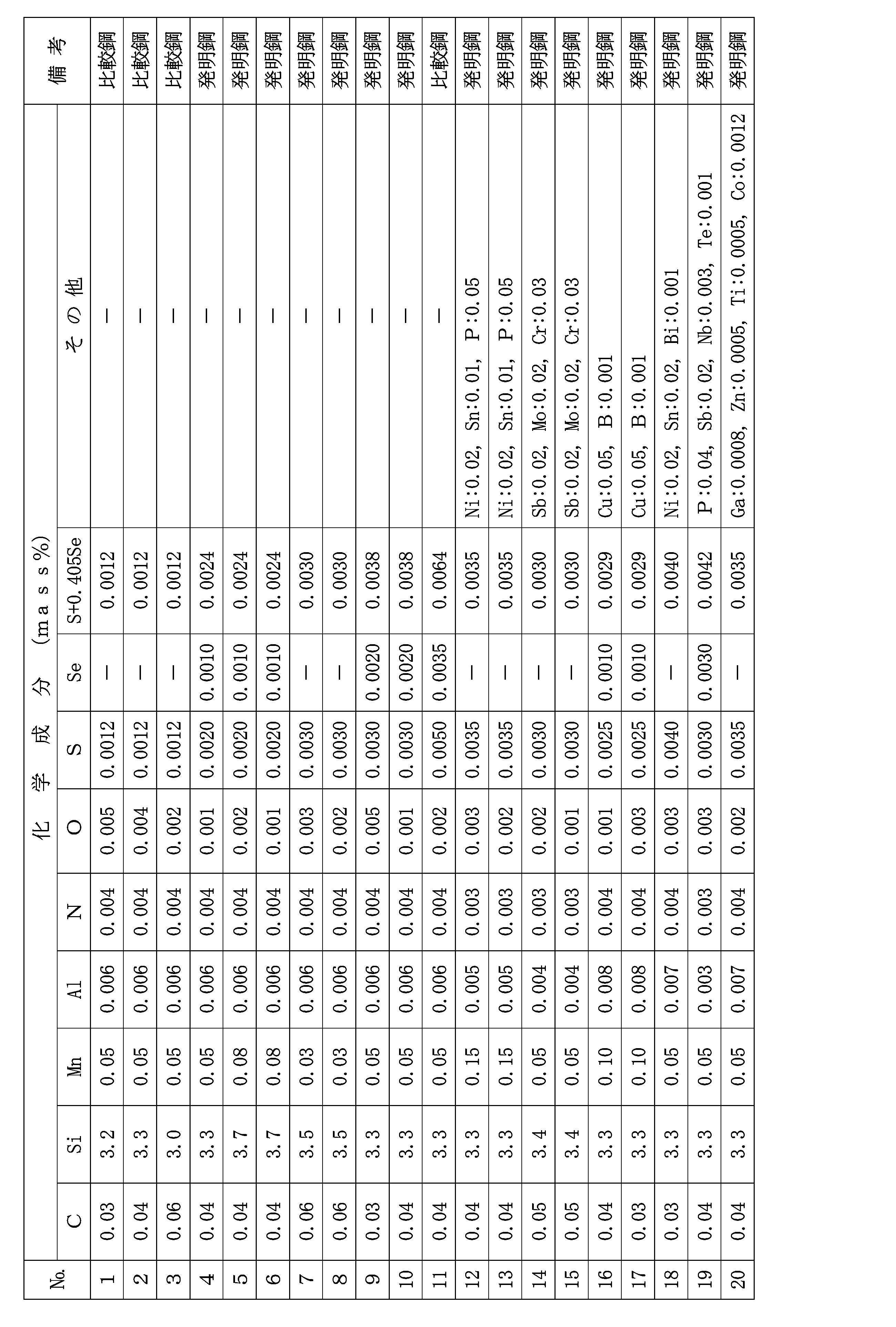
- the present invention based on the above findings includes C: 0.03 to 0.08 mass%, Si: 2.0 to 5.0 mass%, Mn: 0.005 to 1.0 mass%, Al: less than 0.010 mass%, N : 0.006 mass% or less and O: 0.0060 mass% or less, and contains S and Se in the range of 0.0015 to 0.0060 mass% (S+0.405 ⁇ Se), with the balance being Fe and A steel slab having a composition consisting of unavoidable impurities is rolled in at least two consecutive passes in a temperature range of 1050 to 1150°C, and the time between the two passes is 60 seconds or less, and the rolling reduction rate of each pass is 20.
- a hot-rolled plate is subjected to hot-rolled plate annealing, and then cold-rolled or intermediate annealed once.
- a method for producing a grain-oriented electrical steel sheet in which a cold-rolled sheet is obtained by sandwiching and cold rolling two or more times, and the cold-rolled sheet is subjected to decarburization annealing that also serves as primary recrystallization annealing, and then finish annealing. .
- the hot rolling in the method for producing grain-oriented electrical steel sheets of the present invention is performed at least one pass at a temperature range of 850 to 950°C, and the hot rolled sheet annealing after the hot rolling is performed at a temperature of 850°C or higher.
- the sum of the cooling time from 750°C to 650°C in the cooling process after hot rolling and the heating time from 600°C to 700°C in the heating process of hot-rolled sheet annealing is 20 seconds or less. shall be.
- the method for manufacturing a grain-oriented electrical steel sheet of the present invention is characterized in that after at least one pass of rolling in the temperature range of 850 to 950° C., the steel sheet is held as it is for 1.0 seconds or more.
- the steel slab in the method for producing a grain-oriented electrical steel sheet of the present invention is characterized in that, in addition to the above-mentioned composition, it further contains at least one component selected from the following groups A to C. - Group A; Ni: 1.50 mass% or less - Group B; Sn: 0.50 mass% or less, Sb: 0.50 mass% or less, Cu: 0.50 mass% or less, Mo: 0.50 mass% or less, Co: At least one species selected from 0.0100 mass% or less, P: 0.50 mass% or less, Cr: 1.50 mass% or less, B: 0.0200 mass% or less, and Bi: 0.0200 mass% or less - Group C; Nb: 0 At least one type selected from .0200 mass% or less, Ti: 0.0200 mass% or less, Te: 0.0200 mass% or less, Ga: 0.0100 mass% or less, and Zn: 0.500 mass% or less.
- the present invention provides C: 0.03 to 0.08 mass%, Si: 2.0 to 5.0 mass%, Mn: 0.005 to 1.0 mass%, Al: less than 0.010 mass%, N: 0 .006 mass% or less and O: 0.0060 mass% or less, and contains S and Se in the range of 0.0015 to 0.0060 mass% (S + 0.405 ⁇ Se), the balance being Fe and unavoidable Sulfides, selenides, and other substances having a composition consisting of impurities and having a major axis of 4 ⁇ m or more and existing within a region 50 mm 2 of 1/5 width of the plate including the center of the plate thickness in the plate thickness cross section along the rolling direction.
- This is a hot-rolled sheet for grain-oriented electrical steel sheet in which the number density of precipitates composed of compounds of is 0.30 pieces/mm 2 or less.
- the above-mentioned hot rolled sheet of the present invention is characterized in that, in addition to the above-mentioned component composition, it further contains at least one group of components selected from the following groups A to C. - Group A; Ni: 1.50 mass% or less - Group B; Sn: 0.50 mass% or less, Sb: 0.50 mass% or less, Cu: 0.50 mass% or less, Mo: 0.50 mass% or less, Co: At least one species selected from 0.0100 mass% or less, P: 0.50 mass% or less, Cr: 1.50 mass% or less, B: 0.0200 mass% or less, and Bi: 0.0200 mass% or less - Group C; Nb: 0 At least one type selected from .0200 mass% or less, Ti: 0.0200 mass% or less, Te: 0.0200 mass% or less, Ga: 0.0100 mass% or less, and Zn: 0.500 mass% or less.
- the present invention it is possible to improve the cold rollability of a hot-rolled sheet that does not contain inhibitor-forming components, so that grain-oriented electrical steel sheets with good magnetic properties can be prevented from breaking during cold rolling. This makes it possible to manufacture stably without any problems.
- S is generally removed by being incorporated into slag during the refining process of steelmaking, but many elements including C are removed by oxidation, so once the removed S During oxidation treatment, slag may return to the steel, so-called "resulfurization". Therefore, in order to stably reduce S, it is necessary to add a large amount of auxiliary raw materials, which is a factor in increasing manufacturing costs.
- Se is often introduced not from raw materials but from scrap used for cost reduction, but it has the same difficulty as S when it comes to removal. Therefore, in the production of grain-oriented electrical steel sheets, steel materials containing S and Se within a range that does not cause problems with secondary recrystallization are used.
- S and Se are also known to be elements that tend to cause segregation.
- S and Se segregate at the center of the thickness of the slab where it finally solidifies, resulting in high concentration. Furthermore, precipitates such as sulfides and selenides are formed. The center segregation and precipitates are melted and diffused and reduced by heating the slab prior to hot rolling. However, when the content of S or Se is high or when the slab heating temperature is low, sulfides and selenides may remain as precipitates in the center of the thickness of the slab.
- the slab may be heated before hot rolling so that the inhibitor-forming component is completely dissolved in solid solution.
- the advantage of the manufacturing method of grain-oriented electrical steel sheets using steel materials that do not use inhibitors is that manufacturing costs can be reduced by lowering the heating temperature of the slab, and this advantage cannot be achieved by heating the slab at a high temperature. cannot enjoy it.
- a conventional method using an inhibitor may be applied.
- the inventors developed a method in which sulfides and selenides, which exist as precipitates near the center of the thickness of the slab due to center segregation, are completely dissolved in solid solution by heating the slab at high temperature. We considered ways to destroy and render it harmless. As a result, it has been found that this can be achieved by performing at least two successive passes of rolling under high pressure and high strain rate under appropriate conditions in a specific hot rolling temperature range.
- the present invention removes large sulfide and selenide precipitates present in the center of the slab by hot rolling at least two successive passes under appropriate conditions in a specific temperature range (1050 to 1150°C). It is characterized in that it does not break during cold rolling and breaks to a size with a major axis of less than 4 ⁇ m.
- hot rolling of Si-containing steel is carried out in a temperature range where almost a single layer of ferrite is formed, but the above temperature range corresponds to the temperature range where austenite is formed, albeit in a small amount, for reasons explained below.
- C is set in the range of 0.03 to 0.08 mass%. It is preferably in the range of 0.03 to 0.06 mass%.
- Si:2.0 ⁇ 5.0mass% Si is an effective element for increasing the resistivity of steel and reducing iron loss, and in order to fully obtain this effect, it is necessary to contain at least 2.0 mass%.
- the upper limit is set at 5.0 mass%. .
- it is in the range of 2.8 to 4.5 mass%.
- Mn 0.005 to 1.0 mass% Since Mn has the effect of improving hot workability and is also a useful element from the viewpoint of controlling the oxide film formed during primary recrystallization, it is contained in an amount of 0.005 mass% or more. On the other hand, if it exceeds 1.0 mass%, the primary recrystallization texture deteriorates, leading to deterioration of magnetic properties, so the upper limit is set to 1.0 mass%. It is preferably in the range of 0.01 to 0.5 mass%.
- Al less than 0.010 mass%
- N 0.006 mass% or less
- the present invention is a technology for manufacturing a grain-oriented electrical steel sheet using a steel material that does not contain inhibitor-forming components. Therefore, Al is limited to less than 0.010 mass%, and N is limited to 0.006 mass% or less. When Al and N exceed the above values, it becomes difficult to obtain a good secondary recrystallized structure even if the structure is controlled. Further, N needs to be 0.006 mass % or less from the viewpoint of preventing deterioration of magnetic properties due to generation of Si nitrides during purification annealing of final annealing.
- Al 0.008 mass% or less
- N 0.0050 mass% or less.
- O forms an oxide and deteriorates the magnetic properties of the final product board, so it is limited to 0.0060 mass% or less. Preferably, it is 0.0030 mass% or less.
- S and Se are harmful elements in the present invention, forming sulfides and selenides that cause breakage during cold rolling, and forming inhibitors and deteriorating magnetic properties, so they are basically low. The more desirable.
- S and Se need to be reduced to 0.0060 mass% or less (S+0.405 ⁇ Se).
- the lower limit of (S + 0.405 x Se) is set at 0.0015 mass%. degree. Preferably, it is in the range of 0.0020 to 0.0050 mass%.
- the remainder other than the above components is basically Fe and inevitable impurities.
- at least one component selected from the following components may be included.
- Ni 1.50 mass% or less
- Ni is an element useful for improving the steel plate structure of hot rolled sheets and improving magnetic properties, and in order to obtain this effect, it is preferable to add 0.005 mass% or more.
- the upper limit is preferably 1.50 mass%. More preferably, it is in the range of 0.01 to 1.00 mass%.
- Sn 0.50 mass% or less
- Sb 0.50 mass% or less
- Cu 0.50 mass% or less
- Mo 0.50 mass% or less
- Co 0.0100 mass% or less
- P 0.50 mass% or less
- Cr At least one selected from 1.50 mass% or less
- B 0.0200 mass% or less
- Bi 0.0200 mass% or less
- Sn, Sb, Cu, Mo, Co, P, Cr, B and Bi are grain boundary segregation It is an element that has the effect of improving magnetic properties. However, when the upper limit of the above range is exceeded, the development of secondary recrystallized grains is rather inhibited. Therefore, when it is added, it is preferable to add it to the above-mentioned upper limit or less.
- Sn 0.01 mass% or more
- Sb 0.005 mass% or more
- Cu 0.01 mass% or more
- Mo 0.01 mass% or more
- Co 0.0001 mass%.
- P 0.0050 mass% or more
- Cr 0.01 mass% or more
- B 0.0005 mass% or more
- Bi 0.0005 mass% or more.
- Nb, Ti, Te , Ga, and Zn are elements that form carbonitride precipitates, and are not necessarily required in a production method that does not use an inhibitor, but as long as they are within the range where they can be dissolved even by heating the slab at a relatively low temperature. Addition of a very small amount has the effect of improving magnetic properties. However, addition exceeding the above upper limit makes secondary recrystallization unstable. Furthermore, even within the above range, secondary recrystallization may become unstable depending on the slab heating temperature and manufacturing conditions, so care must be taken when using it.
- Nb 0.0005 mass% or more
- Ti 0.0005 mass% or more
- Te 0.0005 mass% or more
- Ga 0.0001 mass% or more
- Zn 0.0001 mass%. It is preferable to add % or more.
- the steel material (slab) used in the production of the grain-oriented electrical steel sheet of the present invention is prepared by processing steel adjusted to a composition compatible with the present invention as described above using a converter or electric furnace, and further vacuum degassing if necessary. After being melted using a known refining method that includes processing, etc., it is usually manufactured using a known continuous casting method. Note that a thin slab having a thickness of 100 mm or less may be manufactured using a direct casting method.
- the above-mentioned slab is heated to a predetermined temperature and then subjected to hot rolling, but after continuous casting, it may be immediately subjected to hot rolling without heating.
- the heating temperature of the slab before hot rolling is preferably 1250°C or less. This is because in the component system of the present invention that does not contain an inhibitor-forming component, there is no need to dissolve the inhibitor-forming component in solid solution. However, if the slab heating temperature is too low, the load of hot rolling increases, which may impede manufacturing stability. Further, as will be described later, in the present invention, it is essential to carry out hot rolling at 1050°C or higher in at least two consecutive passes, so the heating temperature is preferably 1100°C or higher.
- the slab heated to a relatively low temperature is then subjected to hot rolling consisting of rough rolling and finish rolling to form a hot rolled steel plate (hot rolled sheet).
- hot rolling consisting of rough rolling and finish rolling to form a hot rolled steel plate (hot rolled sheet).
- the precipitates of sulfides and selenides that segregate and precipitate in the center of the thickness of the slab during slab manufacturing, or the precipitates that are a composite of these compounds are completely solidified. It may remain unmelted and deteriorate cold rolling properties.
- the present invention in order to destroy the large sulfide and selenide precipitates that are harmful to the above-mentioned cold rolling and make them harmless, in the above-mentioned hot rolling, at least two consecutive passes are carried out at 1050°C. It is necessary to carry out the process in a temperature range of ⁇ 1150°C, the time between the two passes is 60 s or less, the rolling reduction rate of each pass in the 2 passes is 20% or more, and the strain rate is 15 s -1 or more. .
- the temperature range of 1050 to 1150°C is the temperature range in which austenite is formed in ferrite.
- Austenite has higher deformation resistance than ferrite, and is less likely to deform even when rolled down. Therefore, when austenite exists, the surrounding ferrite is forced to undergo non-uniform deformation. Therefore, rolling in this temperature range greatly contributes to the destruction of precipitates such as sulfides and selenides precipitated in ferrite.
- the above-mentioned destructive effect becomes larger as the amount of strain applied increases, so in the present invention, the reduction ratio of rolling in the above-mentioned temperature range is set to 20% or more. Preferably it is 25% or more.
- the strain rate of each pass is 18 s -1 or more, and the interpass time is 50 s or less.
- the strain rate is a value calculated using Ekelund's equation below.
- v R Roll circumferential speed (mm/s)
- R' Roll radius (mm)
- h 1 Roll entrance plate thickness (mm)
- r Roll reduction rate (%)
- the above hot rolling conditions it becomes possible to destroy large sulfide or selenide precipitates or their composite precipitates that exist near the center of the thickness of the hot rolled steel sheet.
- the number density of precipitates with a major axis of 4 ⁇ m or more which is harmful to cold rolling and exists in the center of the sheet thickness cross section, can be reduced to 0.30 pieces/mm 2 or less.
- a more preferable number density of precipitates is 0.1 pieces/mm 2 or less.
- the number density of precipitates such as sulfides and selenides is determined by taking a test piece from the center of the width of the hot-rolled sheet, and measuring the thickness of the cross-section of the test piece along the rolling direction, up and down from the center of the thickness.
- An area of 1/10 of the plate thickness that is, an area of 1/5 width of the plate including the center of the plate thickness over 50 mm2 , was observed using a scanning electron microscope (SEM) to detect sulfides, selenides, and their compounds. It is measured by counting the number of precipitates having a major axis of 4 ⁇ m or more among the precipitates in which the precipitates are combined.
- the steel plate is without processing for 1.0 seconds or more after passing in the temperature range of 850° C. or higher and 950° C. or lower.
- the above-mentioned pass in which rolling is held for 1.0 seconds or more after the pass means that rolling can be carried out in the temperature range of 850 to 950°C, and if it is possible to hold the roll for 1.0 seconds or more without processing after the pass, then hot rolling is required.
- Any pass of rolling may be used.
- the first pass of finish rolling where the rolling speed is slow and the time until the next pass is long, or the final pass of finish rolling, where the time from rolling to the start of cooling can be freely set, is suitable.
- the above-mentioned hot-rolled steel plate is cooled and wound into a coil, and then subjected to hot-rolled plate annealing.
- the cooling time from 750°C to 650°C in the cooling process after hot rolling and the maximum temperature reached during hot-rolled sheet annealing (850°C or higher) are required. It is important to limit the sum of the heating time from 600° C. to 700° C. to 20 seconds or less.
- the maximum temperature reached during hot-rolled sheet annealing is preferably 850° C. or higher from the viewpoint of promoting recrystallization and highly developing the Goss structure in the product sheet. If the hot-rolled sheet annealing temperature is less than 850°C, the band structure formed by hot rolling remains, making it difficult to obtain a well-grained primary recrystallized structure and inhibiting the development of secondary recrystallization. There is a possibility that
- the upper limit of the hot rolled sheet annealing temperature is preferably about 1130°C.
- the temperature exceeds 1130°C inhibitor-forming components that are inevitably mixed into the steel dissolve into solid solution and re-precipitate non-uniformly during cooling, making it difficult to obtain a well-grained primary recrystallized structure and secondary recrystallization. There is a possibility that crystal development may be inhibited.
- the annealing temperature exceeds 1130°C the grain size after annealing becomes too coarse, which is also disadvantageous in obtaining a well-grained primary recrystallized structure.
- the steel plate after the above-mentioned hot rolled plate annealing is cold rolled once or twice or more with intermediate annealing in between to obtain a cold rolled plate having the final plate thickness (product plate thickness).
- final cold rolling from the viewpoint of developing the Goss structure, warm rolling is adopted in which the steel plate temperature during rolling is raised to 80 to 150 ° C. It is desirable to perform inter-pass aging, in which the steel sheet temperature is increased to 100 to 300° C. between passes, one or more times.
- the cold-rolled sheet having the final thickness is then subjected to decarburization annealing that also serves as primary recrystallization annealing.
- the purpose of this annealing is to primary recrystallize a cold-rolled sheet with a rolled structure to obtain a primary recrystallized structure that is optimal for secondary recrystallization, and to reduce C in the steel to 0.0050 mass, which prevents magnetic aging from occurring. % or less, preferably 0.0030 mass% or less, and form an oxide film layer (subscale) necessary for forming a forsterite film on the surface layer of the steel sheet.
- the atmosphere in the decarburization annealing is preferably an oxidizing atmosphere containing H 2 such as wet hydrogen nitrogen or wet hydrogen argon, and the soaking temperature is preferably in the range of 750 to 900°C. Further, when heating to the above soaking temperature, the texture of the primary recrystallized structure can be further improved by setting the heating rate between 550 and 680° C. to 100° C./s. More preferably it is 200°C/s or more. Further, after decarburization annealing, a siliconizing treatment to increase the amount of Si may be performed.
- the steel plate after the decarburization annealing is then coated with an annealing separator on the surface of the steel plate, and then subjected to final annealing for secondary recrystallization to develop Goss-oriented ( ⁇ 110 ⁇ 001>) grains.
- an annealing separator containing MgO as a main component may be used to form a forsterite film on the surface of the steel sheet during final annealing.
- the formation of the forsterite film can be further promoted by adding an appropriate amount of an auxiliary agent such as a Ti oxide or a Sr compound to the annealing separator.
- auxiliary agent that uniformizes the formation of the forsterite film also works advantageously to improve the peeling resistance of the film.
- an annealing separator containing Al 2 O 3 or the like as the main component may be used to suppress film formation.
- the final annealing described above is preferably heated to a temperature of 800° C. or higher in order to induce secondary recrystallization.
- the atmosphere for final annealing may be N 2 , Ar, H 2 or a mixed gas thereof.
- the same effect can be obtained even if the temperature is gradually heated within the above temperature range at a temperature increase rate of 10° C./hr or less, so it is not necessarily necessary to maintain the same temperature.
- the steel plate after the final annealing may then be subjected to flattening annealing to adjust the shape of the steel plate after removing the unreacted annealing separator. Further, in this flattening annealing, or before or after the flattening annealing, an insulating film may be applied and baked on the surface of the steel sheet.
- a conventionally known insulating film can be used. For example, after coating a steel plate with a coating solution containing phosphate-chromate-colloidal silica described in JP-A-48-39338 and JP-A-50-79442, A tension-applied insulation coating that is baked at a temperature is suitable.
- the second pass of rough rolling is at a temperature of 1100°C with a rolling reduction rate of 35% and a strain rate of 30 s -1
- the third pass is a temperature of 1080°C with a rolling reduction rate of 35% and a strain rate of 30 s -1 .
- the inter-pass time of the three passes was 50 seconds.
- finish rolling was performed in a temperature range of 880 to 950°C, and the rolling end temperature of the final pass was 880°C.
- the cooling time from 750°C to 650°C after hot rolling was 7 seconds, and the coil winding temperature was 570°C.
- the above-mentioned hot-rolled sheet was subjected to hot-rolled sheet annealing at a maximum temperature of 1020° C. in a continuous annealing furnace. At this time, the heating time from 600° C. to 700° C. in the heating process was controlled to 11 seconds.
- the hot-rolled annealed steel sheet was cold-rolled to obtain a cold-rolled sheet with a final thickness of 0.260 mm.
- the number of coils that broke during cold rolling was counted. Note that cases in which the same coil broke multiple times or cases in which the coil broke at an unsteady portion at the leading and trailing ends were also counted as one coil's breakage.
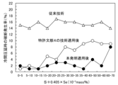
- FIG. 2 is a graph in which the fracture occurrence rate in the cold rolling is organized as (S+0.405 ⁇ Se) and the results are also shown in FIG. 1 mentioned above. From this figure, by applying the hot rolling method and hot rolled sheet annealing conditions of the present invention, the S and Se contents contained in the steel sheet are in a region of 0.0015 mass% or more (S + 0.405 ⁇ Se). It can be seen that the fracture occurrence rate during cold rolling is reduced, especially when (S+0.405 ⁇ Se) is 0.0025 mass% or more, the reduction effect is remarkable.
- the steel plate after cold rolling was subjected to primary recrystallization annealing in which the temperature increase rate between 550 and 680°C during the heating process was 250°C/s, the soaking temperature was 800°C, and the soaking time was 30s.
- Decarburization annealing was performed to reduce C in the steel sheet to 0.0050 mass% or less.
- an annealing separator consisting of 95 mass% MgO and 5 mass% TiO 2 was made into a water slurry and applied to the surface of the steel plate, dried, and then subjected to finish annealing to cause secondary recrystallization.
- a tension-applied insulation film was formed by baking at 800°C.
- the rolling reduction rate and strain rate of the 4th and 5th passes of rough rolling are the same, the first pass of finish rolling is performed at a temperature of 850 to 950°C, and the rolling rate and strain rate of the 4th and 5th passes of rough rolling are
- the inter-pass time, the inter-pass time between the first and second finish rolling passes, the finish rolling end temperature, and the cooling time from 750°C to 650°C after finish rolling were varied as shown in Table 2. I let it happen.
- a test piece was taken from the center in the length direction and the center in the width direction of the hot rolled sheet obtained as described above, and the structure of the cross section of the sheet parallel to the rolling direction was observed using SEM.
- the number density of sulfide and selenide precipitates with a major axis of 4 ⁇ m or more, and precipitates that are composites of these compounds, existing within a 50 mm 2 area of 1/5 width of the plate thickness including the central part of the plate thickness cross section. It was measured.
- the hot-rolled sheet was subjected to hot-rolled sheet annealing at a maximum temperature of 1000°C.
- the heating time from 600° C. to 700° C. in the heating process was varied as shown in Table 2.
- the steel plate after the above-mentioned hot rolled plate annealing was first cold rolled to 1.7 mm at a temperature of 100°C using a reverse rolling mill, and after intermediate annealing at 900°C x 1 min, again, Secondary cold rolling was performed using a reverse rolling mill to obtain a cold rolled sheet with a final thickness of 0.22 mm.
- the fracture occurrence rate of the total of the first cold rolling and the second cold rolling was counted in the same manner as in Example 1.
- inter-pass aging was performed at least once in which the coil wound at 200° C. was held for 0.5 hr or more to undergo aging treatment between multiple passes.
- the steel is subjected to decarburization annealing that also serves as primary recrystallization annealing, with a heating rate of 300°C/s between 550°C and 680°C, a soaking temperature of 840°C, and a soaking time of 60 seconds.
- the C content was reduced to 0.0050 mass% or less.
- an annealing separator consisting of 95 mass% MgO and 5 mass% TiO 2 was made into a water slurry and applied to the surface of the steel plate, dried, and then subjected to finish annealing to cause secondary recrystallization.
- a coating liquid containing phosphate-chromate-colloidal silica in a mass ratio of 3:1:3 is applied to the steel plate surface, A tension-applied insulation film was formed by baking at 800°C.
Landscapes
- Chemical & Material Sciences (AREA)
- Engineering & Computer Science (AREA)
- Materials Engineering (AREA)
- Mechanical Engineering (AREA)
- Metallurgy (AREA)
- Organic Chemistry (AREA)
- Physics & Mathematics (AREA)
- Thermal Sciences (AREA)
- Crystallography & Structural Chemistry (AREA)
- Electromagnetism (AREA)
- Manufacturing & Machinery (AREA)
- Dispersion Chemistry (AREA)
- Power Engineering (AREA)
- Manufacturing Of Steel Electrode Plates (AREA)
- Soft Magnetic Materials (AREA)
Abstract
Description
記
・A群;Ni:1.50mass%以下
・B群;Sn:0.50mass%以下、Sb:0.50mass%以下、Cu:0.50mass%以下、Mo:0.50mass%以下、Co:0.0100mass%以下、P:0.50mass%以下、Cr:1.50mass%以下、B:0.0200mass%以下およびBi:0.0200mass%以下から選ばれる少なくとも1種
・C群;Nb:0.0200mass%以下、Ti:0.0200mass%以下、Te:0.0200mass%以下、Ga:0.0100mass%以下およびZn:0.500mass%以下から選ばれる少なくとも1種
記
・A群;Ni:1.50mass%以下
・B群;Sn:0.50mass%以下、Sb:0.50mass%以下、Cu:0.50mass%以下、Mo:0.50mass%以下、Co:0.0100mass%以下、P:0.50mass%以下、Cr:1.50mass%以下、B:0.0200mass%以下およびBi:0.0200mass%以下から選ばれる少なくとも1種
・C群;Nb:0.0200mass%以下、Ti:0.0200mass%以下、Te:0.0200mass%以下、Ga:0.0100mass%以下およびZn:0.500mass%以下から選ばれる少なくとも1種
発明者らは、特許文献4の技術を適用してもなお、冷間圧延時に破断を起こしたコイルについて詳細な調査を行った。その結果、鋼板が破断を起こした部分には、鋼板が表裏に分離して2枚板状になっている部分が認められた。
従来のインヒビターを用いない方向性電磁鋼板の製造方法、例えば、特許文献4に記載の製造方法では、SおよびSeをそれぞれ0.0050mass%以下に低減して高純度化した鋼素材を用い、熱延板の集合組織を適正に制御することによって二次再結晶を発現させている。そのため、SやSeは、基本的には低ければ低いほど二次再結晶は安定して発現すると考えられており、特許文献4においても、SとSeの含有量をそれぞれ0~0.0020mass%程度まで低減している。
本発明は、上記の知見にさらに改良を加えて完成したものである。
C:0.03~0.08mass%
本発明は、スラブの中心部に存在する大きな硫化物やセレン化物の析出物を、特定の温度域(1050~1150℃)で適正な条件で少なくとも連続する2パスの熱間圧延を施すことで、冷間圧延時に破断を起こすことがない、長径が4μm未満の大きさに破壊することを特徴としている。通常、Si含有鋼の熱間圧延は、ほぼフェライト単層となる温度域で行っているが、上記温度域は、少量ではあるがオーステナイトが形成される温度域と一致しており、後述する理由により、硫化物やセレン化物の析出物が、分断、破壊され易くなる。そこで、上記2相域での熱間圧延を可能とするため、Cを0.03mass%以上含有させる。一方、Cが0.08mass%を超えると、脱炭焼鈍を施しても磁気時効の起こらない0.0050mass%以下に低減することが難しくなる。よって、Cは0.03~0.08mass%の範囲とする。好ましくは0.03~0.06mass%の範囲である。
Siは、鋼の固有抵抗を高めて鉄損を低減するのに有効な元素であり、この効果を十分に得るためには、少なくとも2.0mass%を含有させる必要がある。一方、5.0mass%を超えると、鋼が脆化し、冷間圧延性が著しく劣化したり、製造設備への通板時に破断を起こしたりするリスクが高まるので、上限は5.0mass%とする。好ましくは、2.8~4.5mass%の範囲である。
Mnは、熱間加工性を向上させる効果があり、また、一次再結晶時に形成される酸化被膜を制御する観点からも有用な元素であるので、0.005mass%以上含有させる。一方、1.0mass%を超えると、一次再結晶集合組織が悪化し、磁気特性の劣化を招くので、上限は1.0mass%とする。好ましくは0.01~0.5mass%の範囲である。
本発明は、インヒビター形成成分を含有していない鋼素材を用いて方向性電磁鋼板を製造する技術である。したがって、Alは0.010mass%未満、Nは0.006mass%以下に制限する。AlおよびNが上記値を超えると、組織制御しても良好な二次再結晶組織を得ることが難しくなる。また、Nは、仕上焼鈍の純化焼鈍時にSi窒化物が生成して磁気特性が劣化するのを防止する観点からも0.006mass%以下とする必要がある。好ましくは、Al:0.008mass%以下、N:0.0050mass%以下である。
Oは、酸化物を形成し、最終製品板の磁気特性を劣化させるので0.0060mass%以下に制限する。好ましくは、0.0030mass%以下である。
SおよびSeは、硫化物やセレン化物を形成して冷間圧延時に破断を引き起こしたり、インヒビターを形成して磁気特性を劣化したりする本発明においては有害元素であるため、基本的には低いほど望ましい。特に、インヒビターを用いずに二次再結晶を安定的に発現させるためには、SとSeは(S+0.405×Se)で0.0060mass%以下に低減する必要がある。しかし、SおよびSeの過度な低減は、磁気特性や冷延での破断に対して悪影響はないが、製造コストの上昇を招くため、(S+0.405×Se)の下限は、0.0015mass%程度とする。好ましくは、0.0020~0.0050mass%の範囲である。
Niは、熱延板の鋼板組織を改善して磁気特性を向上させるのに有用な元素であり、この効果を得るためには0.005mass%以上添加するのが好ましい。一方、Niの過剰な添加は二次再結晶が不安定化し、磁気特性が却って劣化するようになるので、上限は1.50mass%とするのが好ましい。より好ましくは0.01~1.00mass%の範囲である。
Sn、Sb、Cu、Mo、Co、P、Cr、BおよびBiは、粒界偏析型の元素であり、磁気特性を向上する効果がある。しかし、上記範囲の上限値を超えると、二次再結晶粒の発達が却って阻害されるようになる。よって、添加する場合は、上記上限値以下とするのが好ましい。なお、上記添加効果を確実に得るためには、Sn:0.01mass%以上、Sb:0.005mass%以上、Cu:0.01mass%以上、Mo:0.01mass%以上、Co:0.0001mass%以上、P:0.0050mass%以上、Cr:0.01mass%以上、B:0.0005mass%以上およびBi:0.0005mass%以上添加するのが好ましい。
Nb、Ti、Te、GaおよびZnは、炭窒化物の析出物を形成する元素であり、インヒビターを用いない製造法においては必ずしも必要ではないが、比較的低温のスラブ加熱でも固溶可能な範囲内であれば、極微量の添加で磁気特性を改善する効果がある。しかし、上記の上限値を超える添加は、二次再結晶を不安定にする。また、上記範囲内であっても、スラブ加熱温度や製造条件によっては、二次再結晶を不安定にする場合もあるので、使用にあたっては注意を要する。なお、上記添加効果を確実に得るためには、Nb:0.0005mass%以上、Ti:0.0005mass%以上、Te:0.0005mass%以上、Ga:0.0001mass%以上およびZn:0.0001mass%以上添加するのが好ましい。
本発明の方向性電磁鋼板の製造に用いる鋼素材(スラブ)は、上記した本発明に適合する成分組成に調整した鋼を、転炉や電気炉などを用い、必要があればさらに真空脱ガス処理などを施す公知の精錬方法で溶製した後、通常公知の連続鋳造法で製造する。なお、直接鋳造法を用いて100mm以下の厚さの薄鋳片を製造してもよい。


Claims (6)
- C:0.03~0.08mass%、Si:2.0~5.0mass%、Mn:0.005~1.0mass%、Al:0.010mass%未満、N:0.006mass%以下およびO:0.0060mass%以下を含有し、かつ、SとSeを(S+0.405×Se)で0.0015~0.0060mass%の範囲で含有し、残部がFeおよび不可避的不純物からなる成分組成を有する鋼スラブを、少なくとも連続する2パスの圧延を1050~1150℃の温度域で行うとともに、上記2パスのパス間時間を60s以下、各パスの圧下率を20%以上、歪速度を15s-1以上とすることを含む熱間圧延をして熱延板とし、該熱延板に熱延板焼鈍を施した後、1回の冷間圧延または中間焼鈍を挟む2回以上の冷間圧延をして冷延板とし、該冷延板に一次再結晶焼鈍を兼ねた脱炭焼鈍を施した後、仕上焼鈍を施す方向性電磁鋼板の製造方法。
- 上記熱間圧延は、少なくとも1パスを850~950℃の温度域で行い、
上記熱間圧延後の熱延板焼鈍は、850℃以上の温度で行うとともに、
上記熱間圧延後の冷却過程の750℃から650℃までの冷却時間と上記熱延板焼鈍の加熱過程の600℃から700℃までの加熱時間の和を20s以下とすることを特徴とする請求項1に記載の方向性電磁鋼板の製造方法。 - 上記850~950℃の温度域での少なくとも1パスの圧延後、鋼板をそのままの状態で1.0s以上保持することを特徴とする請求項2に記載の方向性電磁鋼板の製造方法。
- 上記鋼スラブは、上記成分組成に加えてさらに、下記のA~C群から選ばれる少なくとも1群の成分を含有することを特徴とする請求項1~3のいずれか1項に記載の方向性電磁鋼板の製造方法。
記
・A群;Ni:1.50mass%以下
・B群;Sn:0.50mass%以下、Sb:0.50mass%以下、Cu:0.50mass%以下、Mo:0.50mass%以下、Co:0.0100mass%以下、P:0.50mass%以下、Cr:1.50mass%以下、B:0.0200mass%以下およびBi:0.0200mass%以下から選ばれる少なくとも1種
・C群;Nb:0.0200mass%以下、Ti:0.0200mass%以下、Te:0.0200mass%以下、Ga:0.0100mass%以下およびZn:0.500mass%以下から選ばれる少なくとも1種 - C:0.03~0.08mass%、Si:2.0~5.0mass%、Mn:0.005~1.0mass%、Al:0.010mass%未満、N:0.006mass%以下およびO:0.0060mass%以下を含有し、かつ、SとSeを(S+0.405×Se)で0.0015~0.0060mass%の範囲で含有し、残部がFeおよび不可避的不純物からなる成分組成を有し、
圧延方向に沿った板厚断面の板厚中心部を含む板厚1/5幅の領域50mm2内に存在する長径が4μm以上の硫化物、セレン化物およびそれらの化合物が複合した析出物の個数密度が0.30個/mm2以下である方向性電磁鋼板用の熱延板。 - 上記成分組成に加えてさらに、下記のA~C群から選ばれる少なくとも1群の成分を含有することを特徴とする請求項5に記載の方向性電磁鋼板用の熱延板。
記
・A群;Ni:1.50mass%以下
・B群;Sn:0.50mass%以下、Sb:0.50mass%以下、Cu:0.50mass%以下、Mo:0.50mass%以下、Co:0.0100mass%以下、P:0.50mass%以下、Cr:1.50mass%以下、B:0.0200mass%以下およびBi:0.0200mass%以下から選ばれる少なくとも1種
・C群;Nb:0.0200mass%以下、Ti:0.0200mass%以下、Te:0.0200mass%以下、Ga:0.0100mass%以下およびZn:0.500mass%以下から選ばれる少なくとも1種
Priority Applications (6)
| Application Number | Priority Date | Filing Date | Title |
|---|---|---|---|
| US19/104,754 US20260062773A1 (en) | 2022-08-24 | 2023-08-24 | Method for producing grain-oriented electrical steel sheet and hot-rolled sheet for grain-oriented electrical steel sheet |
| JP2024514687A JPWO2024043294A1 (ja) | 2022-08-24 | 2023-08-24 | |
| KR1020257003701A KR20250034971A (ko) | 2022-08-24 | 2023-08-24 | 방향성 전기 강판의 제조 방법 및 방향성 전기 강판용의 열연판 |
| EP23857402.4A EP4560032A4 (en) | 2022-08-24 | 2023-08-24 | METHOD FOR PRODUCING GRAIN-ORIENTED ELECTROMAGNETIC STEEL SHEET, AND HOT-ROLLED SHEET FOR GRAIN-ORIENTED ELECTROMAGNETIC STEEL SHEET |
| CN202380060094.9A CN119654426A (zh) | 2022-08-24 | 2023-08-24 | 取向性电磁钢板的制造方法和取向性电磁钢板用热轧板 |
| JP2025265448A JP2026053466A (ja) | 2022-08-24 | 2025-12-18 | 方向性電磁鋼板用の熱延板 |
Applications Claiming Priority (2)
| Application Number | Priority Date | Filing Date | Title |
|---|---|---|---|
| JP2022-133154 | 2022-08-24 | ||
| JP2022133154 | 2022-08-24 |
Publications (1)
| Publication Number | Publication Date |
|---|---|
| WO2024043294A1 true WO2024043294A1 (ja) | 2024-02-29 |
Family
ID=90013464
Family Applications (1)
| Application Number | Title | Priority Date | Filing Date |
|---|---|---|---|
| PCT/JP2023/030414 Ceased WO2024043294A1 (ja) | 2022-08-24 | 2023-08-24 | 方向性電磁鋼板の製造方法および方向性電磁鋼板用の熱延板 |
Country Status (6)
| Country | Link |
|---|---|
| US (1) | US20260062773A1 (ja) |
| EP (1) | EP4560032A4 (ja) |
| JP (2) | JPWO2024043294A1 (ja) |
| KR (1) | KR20250034971A (ja) |
| CN (1) | CN119654426A (ja) |
| WO (1) | WO2024043294A1 (ja) |
Cited By (1)
| Publication number | Priority date | Publication date | Assignee | Title |
|---|---|---|---|---|
| WO2025243810A1 (ja) * | 2024-05-22 | 2025-11-27 | Jfeスチール株式会社 | 方向性電磁鋼板の製造方法 |
Citations (9)
| Publication number | Priority date | Publication date | Assignee | Title |
|---|---|---|---|---|
| JPS4839338A (ja) | 1971-09-27 | 1973-06-09 | ||
| JPS5079442A (ja) | 1973-11-17 | 1975-06-27 | ||
| JPS5113469A (ja) | 1974-06-04 | 1976-02-02 | Voest Ag | |
| JPH05105956A (ja) * | 1991-07-25 | 1993-04-27 | Kawasaki Steel Corp | 板幅方向に均一な磁気特性を有する一方向性けい素鋼板の製造方法 |
| JP2000129356A (ja) | 1998-10-28 | 2000-05-09 | Kawasaki Steel Corp | 方向性電磁鋼板の製造方法 |
| JP2002212639A (ja) * | 2001-01-12 | 2002-07-31 | Nippon Steel Corp | 磁気特性に優れた一方向性珪素鋼板の製造方法 |
| JP2003226916A (ja) | 2002-02-05 | 2003-08-15 | Jfe Steel Kk | 冷間圧延時の板破断が少ない方向性電磁鋼板の製造方法 |
| US20130174940A1 (en) * | 2010-03-19 | 2013-07-11 | Stefano Cicale | Grain oriented steel strip with high magnetic characteristics, and manufacturing process of the same |
| JP2014500399A (ja) * | 2010-12-23 | 2014-01-09 | ポスコ | 磁性に優れた方向性電気鋼板及びその製造方法 |
Family Cites Families (3)
| Publication number | Priority date | Publication date | Assignee | Title |
|---|---|---|---|---|
| US9536657B2 (en) * | 2010-06-29 | 2017-01-03 | Jfe Steel Corporation | Grain oriented electrical steel sheet and method for manufacturing the same |
| US9761360B2 (en) * | 2012-03-29 | 2017-09-12 | Jfe Steel Corporation | Method of manufacturing grain oriented electrical steel sheet |
| JP7392849B2 (ja) * | 2021-01-28 | 2023-12-06 | Jfeスチール株式会社 | 方向性電磁鋼板の製造方法および電磁鋼板製造用圧延設備 |
-
2023
- 2023-08-24 WO PCT/JP2023/030414 patent/WO2024043294A1/ja not_active Ceased
- 2023-08-24 EP EP23857402.4A patent/EP4560032A4/en active Pending
- 2023-08-24 JP JP2024514687A patent/JPWO2024043294A1/ja active Pending
- 2023-08-24 KR KR1020257003701A patent/KR20250034971A/ko active Pending
- 2023-08-24 CN CN202380060094.9A patent/CN119654426A/zh active Pending
- 2023-08-24 US US19/104,754 patent/US20260062773A1/en active Pending
-
2025
- 2025-12-18 JP JP2025265448A patent/JP2026053466A/ja active Pending
Patent Citations (9)
| Publication number | Priority date | Publication date | Assignee | Title |
|---|---|---|---|---|
| JPS4839338A (ja) | 1971-09-27 | 1973-06-09 | ||
| JPS5079442A (ja) | 1973-11-17 | 1975-06-27 | ||
| JPS5113469A (ja) | 1974-06-04 | 1976-02-02 | Voest Ag | |
| JPH05105956A (ja) * | 1991-07-25 | 1993-04-27 | Kawasaki Steel Corp | 板幅方向に均一な磁気特性を有する一方向性けい素鋼板の製造方法 |
| JP2000129356A (ja) | 1998-10-28 | 2000-05-09 | Kawasaki Steel Corp | 方向性電磁鋼板の製造方法 |
| JP2002212639A (ja) * | 2001-01-12 | 2002-07-31 | Nippon Steel Corp | 磁気特性に優れた一方向性珪素鋼板の製造方法 |
| JP2003226916A (ja) | 2002-02-05 | 2003-08-15 | Jfe Steel Kk | 冷間圧延時の板破断が少ない方向性電磁鋼板の製造方法 |
| US20130174940A1 (en) * | 2010-03-19 | 2013-07-11 | Stefano Cicale | Grain oriented steel strip with high magnetic characteristics, and manufacturing process of the same |
| JP2014500399A (ja) * | 2010-12-23 | 2014-01-09 | ポスコ | 磁性に優れた方向性電気鋼板及びその製造方法 |
Non-Patent Citations (1)
| Title |
|---|
| See also references of EP4560032A4 |
Cited By (1)
| Publication number | Priority date | Publication date | Assignee | Title |
|---|---|---|---|---|
| WO2025243810A1 (ja) * | 2024-05-22 | 2025-11-27 | Jfeスチール株式会社 | 方向性電磁鋼板の製造方法 |
Also Published As
| Publication number | Publication date |
|---|---|
| JPWO2024043294A1 (ja) | 2024-02-29 |
| JP2026053466A (ja) | 2026-03-25 |
| KR20250034971A (ko) | 2025-03-11 |
| EP4560032A4 (en) | 2025-10-29 |
| EP4560032A1 (en) | 2025-05-28 |
| CN119654426A (zh) | 2025-03-18 |
| US20260062773A1 (en) | 2026-03-05 |
Similar Documents
| Publication | Publication Date | Title |
|---|---|---|
| JP4258349B2 (ja) | 方向性電磁鋼板の製造方法 | |
| JP5991484B2 (ja) | 低鉄損方向性電磁鋼板の製造方法 | |
| JP5037728B2 (ja) | 一方向性電磁鋼板の製造方法 | |
| EP2025767B2 (en) | Process for producing grain-oriented electrical steel sheet with high magnetic flux density | |
| JP6350398B2 (ja) | 方向性電磁鋼板およびその製造方法 | |
| JP6191780B2 (ja) | 方向性電磁鋼板の製造方法および窒化処理設備 | |
| JP2026053466A (ja) | 方向性電磁鋼板用の熱延板 | |
| JP7824520B2 (ja) | 方向性電磁鋼板の製造方法 | |
| JP2020056105A (ja) | 方向性電磁鋼板の製造方法 | |
| JP5920387B2 (ja) | 方向性電磁鋼板の製造方法 | |
| JP7736157B2 (ja) | 無方向性電磁鋼板とその製造方法 | |
| JP6191564B2 (ja) | 方向性電磁鋼板の製造方法および窒化処理設備 | |
| JP6947147B2 (ja) | 方向性電磁鋼板の製造方法 | |
| JP4259269B2 (ja) | 方向性電磁鋼板の製造方法 | |
| JP4211447B2 (ja) | 方向性電磁鋼板の製造方法 | |
| JP4259025B2 (ja) | ベンド特性に優れる方向性電磁鋼板およびその製造方法 | |
| CN114364821B (zh) | 方向性电磁钢板及其制造方法 | |
| JP5904151B2 (ja) | 方向性電磁鋼板の製造方法 | |
| JP2011111653A (ja) | 方向性電磁鋼板の製造方法 | |
| JP6988845B2 (ja) | 方向性電磁鋼板の製造方法 | |
| JP4626046B2 (ja) | セミプロセス無方向性電磁鋼板の製造方法 | |
| JP6863310B2 (ja) | 方向性電磁鋼板の製造方法 | |
| CN120981593A (zh) | 取向性电磁钢板和卷绕铁芯 | |
| CN113166874A (zh) | 取向电工钢板及其制造方法 | |
| JPH1088234A (ja) | 安定して高い磁束密度を有する方向性珪素鋼板の製造方法 |
Legal Events
| Date | Code | Title | Description |
|---|---|---|---|
| ENP | Entry into the national phase |
Ref document number: 2024514687 Country of ref document: JP Kind code of ref document: A |
|
| 121 | Ep: the epo has been informed by wipo that ep was designated in this application |
Ref document number: 23857402 Country of ref document: EP Kind code of ref document: A1 |
|
| ENP | Entry into the national phase |
Ref document number: 20257003701 Country of ref document: KR Kind code of ref document: A |
|
| WWE | Wipo information: entry into national phase |
Ref document number: 1020257003701 Country of ref document: KR |
|
| WWE | Wipo information: entry into national phase |
Ref document number: 202380060094.9 Country of ref document: CN |
|
| WWE | Wipo information: entry into national phase |
Ref document number: 202517013818 Country of ref document: IN Ref document number: 2023857402 Country of ref document: EP |
|
| ENP | Entry into the national phase |
Ref document number: 2023857402 Country of ref document: EP Effective date: 20250218 |
|
| WWP | Wipo information: published in national office |
Ref document number: 1020257003701 Country of ref document: KR |
|
| WWP | Wipo information: published in national office |
Ref document number: 202517013818 Country of ref document: IN |
|
| WWP | Wipo information: published in national office |
Ref document number: 202380060094.9 Country of ref document: CN |
|
| NENP | Non-entry into the national phase |
Ref country code: DE |
|
| WWP | Wipo information: published in national office |
Ref document number: 2023857402 Country of ref document: EP |