WO2024050976A1 - 一种防泄漏进水管组件 - Google Patents
一种防泄漏进水管组件 Download PDFInfo
- Publication number
- WO2024050976A1 WO2024050976A1 PCT/CN2022/133504 CN2022133504W WO2024050976A1 WO 2024050976 A1 WO2024050976 A1 WO 2024050976A1 CN 2022133504 W CN2022133504 W CN 2022133504W WO 2024050976 A1 WO2024050976 A1 WO 2024050976A1
- Authority
- WO
- WIPO (PCT)
- Prior art keywords
- valve body
- nut
- elbow
- water inlet
- inlet pipe
- Prior art date
- Legal status (The legal status is an assumption and is not a legal conclusion. Google has not performed a legal analysis and makes no representation as to the accuracy of the status listed.)
- Ceased
Links
Images



Classifications
-
- F—MECHANICAL ENGINEERING; LIGHTING; HEATING; WEAPONS; BLASTING
- F16—ENGINEERING ELEMENTS AND UNITS; GENERAL MEASURES FOR PRODUCING AND MAINTAINING EFFECTIVE FUNCTIONING OF MACHINES OR INSTALLATIONS; THERMAL INSULATION IN GENERAL
- F16L—PIPES; JOINTS OR FITTINGS FOR PIPES; SUPPORTS FOR PIPES, CABLES OR PROTECTIVE TUBING; MEANS FOR THERMAL INSULATION IN GENERAL
- F16L11/00—Hoses, i.e. flexible pipes
-
- F—MECHANICAL ENGINEERING; LIGHTING; HEATING; WEAPONS; BLASTING
- F16—ENGINEERING ELEMENTS AND UNITS; GENERAL MEASURES FOR PRODUCING AND MAINTAINING EFFECTIVE FUNCTIONING OF MACHINES OR INSTALLATIONS; THERMAL INSULATION IN GENERAL
- F16L—PIPES; JOINTS OR FITTINGS FOR PIPES; SUPPORTS FOR PIPES, CABLES OR PROTECTIVE TUBING; MEANS FOR THERMAL INSULATION IN GENERAL
- F16L11/00—Hoses, i.e. flexible pipes
- F16L11/22—Multi-channel hoses
-
- F—MECHANICAL ENGINEERING; LIGHTING; HEATING; WEAPONS; BLASTING
- F16—ENGINEERING ELEMENTS AND UNITS; GENERAL MEASURES FOR PRODUCING AND MAINTAINING EFFECTIVE FUNCTIONING OF MACHINES OR INSTALLATIONS; THERMAL INSULATION IN GENERAL
- F16L—PIPES; JOINTS OR FITTINGS FOR PIPES; SUPPORTS FOR PIPES, CABLES OR PROTECTIVE TUBING; MEANS FOR THERMAL INSULATION IN GENERAL
- F16L29/00—Joints with fluid cut-off means
- F16L29/02—Joints with fluid cut-off means with a cut-off device in one of the two pipe ends, the cut-off device being automatically opened when the coupling is applied
-
- F—MECHANICAL ENGINEERING; LIGHTING; HEATING; WEAPONS; BLASTING
- F16—ENGINEERING ELEMENTS AND UNITS; GENERAL MEASURES FOR PRODUCING AND MAINTAINING EFFECTIVE FUNCTIONING OF MACHINES OR INSTALLATIONS; THERMAL INSULATION IN GENERAL
- F16L—PIPES; JOINTS OR FITTINGS FOR PIPES; SUPPORTS FOR PIPES, CABLES OR PROTECTIVE TUBING; MEANS FOR THERMAL INSULATION IN GENERAL
- F16L33/00—Arrangements for connecting hoses to rigid members; Rigid hose-connectors, i.e. single members engaging both hoses
- F16L33/18—Arrangements for connecting hoses to rigid members; Rigid hose-connectors, i.e. single members engaging both hoses characterised by the use of additional sealing means
-
- F—MECHANICAL ENGINEERING; LIGHTING; HEATING; WEAPONS; BLASTING
- F16—ENGINEERING ELEMENTS AND UNITS; GENERAL MEASURES FOR PRODUCING AND MAINTAINING EFFECTIVE FUNCTIONING OF MACHINES OR INSTALLATIONS; THERMAL INSULATION IN GENERAL
- F16L—PIPES; JOINTS OR FITTINGS FOR PIPES; SUPPORTS FOR PIPES, CABLES OR PROTECTIVE TUBING; MEANS FOR THERMAL INSULATION IN GENERAL
- F16L33/00—Arrangements for connecting hoses to rigid members; Rigid hose-connectors, i.e. single members engaging both hoses
- F16L33/24—Arrangements for connecting hoses to rigid members; Rigid hose-connectors, i.e. single members engaging both hoses with parts screwed directly on or into the hose
-
- F—MECHANICAL ENGINEERING; LIGHTING; HEATING; WEAPONS; BLASTING
- F16—ENGINEERING ELEMENTS AND UNITS; GENERAL MEASURES FOR PRODUCING AND MAINTAINING EFFECTIVE FUNCTIONING OF MACHINES OR INSTALLATIONS; THERMAL INSULATION IN GENERAL
- F16L—PIPES; JOINTS OR FITTINGS FOR PIPES; SUPPORTS FOR PIPES, CABLES OR PROTECTIVE TUBING; MEANS FOR THERMAL INSULATION IN GENERAL
- F16L43/00—Bends; Siphons
- F16L43/02—Bends; Siphons adapted to make use of special securing means
-
- F—MECHANICAL ENGINEERING; LIGHTING; HEATING; WEAPONS; BLASTING
- F17—STORING OR DISTRIBUTING GASES OR LIQUIDS
- F17D—PIPE-LINE SYSTEMS; PIPE-LINES
- F17D5/00—Protection or supervision of installations
- F17D5/02—Preventing, monitoring, or locating loss
Definitions
- the invention relates to an anti-leakage water inlet pipe assembly and belongs to the technical field of household appliances.
- the water inlet pipes in existing household appliances such as washing machines and dishwashers are prone to leaking after being used for a long time, and the water pipes may even break, causing water to accumulate in the room.
- this kind of water pipe cannot realize the self-locking water function. Once it breaks or leaks, the water flow cannot be cut off in time, and water will leak continuously from the break. Users cause considerable economic losses.
- the first nut used at the connection between the existing anti-leak water inlet pipe assembly and the washing machine, dishwasher and other equipment is riveted and buckled on the valve body of the anti-leak water inlet pipe assembly. This riveting method is inefficient. The cost is high and cannot meet the demand for batch production of leak-proof water inlet pipe components.
- the present invention provides an anti-leakage water inlet pipe assembly.
- the anti-leakage water inlet pipe assembly can cut off the water flow in time when the inner pipe ruptures, effectively preventing water leakage; and the anti-leakage water inlet pipe assembly can
- the first nut used in the connection with washing machines, dishwashers and other equipment is the second nut, which only needs to be manually buckled on the valve body. It has a simple structure, convenient operation and low production cost, and can meet the needs of batch production of anti-leak water inlet pipe components. .
- the anti-leakage water inlet pipe assembly includes a valve body, a shell is provided around the valve body, a bellows is provided inside the shell, a second nut is set on one end of the valve body, and an inner pipe is connected to the other end.
- One end of the inner tube away from the valve body is connected to an elbow, and a first nut is set on the end of the elbow.
- the inner tube is located in the bellows and has a second chamber between it and the bellows.
- the inner tube is a hollow tube, and the valve body is provided with a central pressure-bearing channel. , the central pressure-bearing channel is connected with the inside of the inner tube, the inside of the inner tube is connected with the inside of the elbow, a first chamber is provided in the housing, and the first chamber is connected with the inside of the elbow.
- the second chamber is connected.
- a valve core assembly is provided in the central pressure-bearing channel.
- the valve core assembly can move in the central pressure-bearing channel.
- One end of the valve core assembly is fixedly connected to a frame, and the frame Expanded cotton is provided inside, and the expanded cotton is connected with the first chamber.
- One end of the expanded cotton is provided with a frame, and the other end is provided with a base.
- a diverter filter is connected to the inside of one end of the valve body close to the second nut.
- the diverter filter includes a filter and a diverter plate disposed on the filter.
- a number of support ribs are provided on the outside of the diverter filter.
- a bottom plate is provided at the bottom of the diverter filter. There is a gap between the bottom plate and the inner wall of the valve body. After the water flows through the diverter plate, it is diverted from the diverter filter. It passes through and flows into the central pressure channel from the gap between the bottom plate and the inner wall of the valve body.
- an aluminum sealing tube is also provided between the valve body and the inner tube; the bent tube is connected to the bellows through a clamp and a buckle, and the bent tube and the inner tube
- An aluminum sealing tube is also provided between the elbow and the bellows; an elbow sealing sleeve is provided between the elbow and the bellows, and an elbow sealing ring slope is provided on the side of the elbow sealing sleeve close to the housing. A slope is provided on one side of the inner tube.
- an elbow gasket is provided in the first nut, a notch is provided at an end of the elbow, and the elbow gasket is embedded in the notch.
- a groove is provided on the valve body, a first sealing ring is embedded between the housing and the groove of the valve body, and the valve core assembly is provided with a The second sealing ring is provided with an inclined surface in the valve body.
- the second nut is clamped on the valve body, and a rubber pad is provided inside the second nut, and the rubber pad conflicts with the side end disk surface of the valve body;
- the second nut is also provided with an inner buckle, and the inner buckle is located between the second nut and the valve body and abuts with the valve body;
- the second nut is provided with a step, and the inner buckle is in contact with the step.
- the second nut and the inner buckle are made of plastic.
- a sealing sleeve is provided between the housing and the bellows, a sight glass is provided at the bottom end of the housing, and a sight glass is provided between the sight glass and the housing. Sight glass seal.
- the present invention can cut off the water flow in time when the inner pipe ruptures, effectively preventing water leakage; and the first nut used at the connection between the anti-leakage water inlet pipe assembly and the washing machine, dishwasher and other equipment is the second nut. It only needs to be manually buckled on the valve body. It has a simple structure, convenient operation and low production cost, and can meet the needs of batch production of leak-proof water inlet pipe components.
- valve core assembly of the present invention moves to the right, the second sealing ring contacts and seals with the inclined surface in the valve body to cut off the communication between the central pressure channel and the faucet assembly, thereby cutting off the water flow and preventing water leakage.
- the aluminum sealing tube of the present invention makes the connection between the valve body and the inner tube closer and prevents water leakage in the inner tube.
- a first sealing ring is provided between the casing and the valve body of the present invention.
- the first sealing ring is used to seal the first chamber to prevent water leakage in the first chamber;
- the connection between the casing and the bellows is
- a sealing sleeve is provided between the two chambers, and the sealing sleeve is used to seal the first chamber to prevent water leakage in the first chamber.
- the frame moves to the right, and the color of the frame is red.
- the sight glass displays red.
- the sight glass is transparent, indicating that the anti-leakage water pipe assembly enters a self-locking state. This When it is necessary to replace the water pipe with a new one, it is practical, simple and easy to operate. It can remind users to replace the water pipe in time.
- the diverter filter of the present invention is used to guide water flow from the side of the valve core assembly to prevent the water flow from directly impacting the valve core assembly below, causing the water inlet assembly to self-lock; the support ribs provided can prevent the diverter filter from Deformation occurs to prevent the diverter filter from being squeezed together when the diverter filter is ejected from the mold because its plastic material is soft when it is not completely cooled.
- the second nut of the present invention is provided with a step, and the inner buckle matches the step; after the inner buckle is inserted into the second nut, the steps provided by the second nut prevent the inner buckle from being opened from the second nut.
- the inner buckle and the second nut are both made of plastic. Since the plastic parts After the mold is released, the inner buckle will shrink inward.
- the inner buckle is set in a C shape. The diameter of the inner buckle will be enlarged during the design so that the inner buckle will exactly meet the required size after shrinkage; install the inner buckle on the valve body 1. Buckle, just manually tighten the second nut
- Figure 1 is a perspective view of the anti-leakage water inlet pipe assembly of the present invention.
- Figure 2 is another perspective view of the anti-leakage water inlet pipe assembly of the present invention.
- Figure 3 is a cross-sectional view of the anti-leakage water inlet pipe assembly of the present invention.
- Figure 4 is an enlarged view of the A direction in Figure 3.
- Figure 5 is an enlarged view of direction B in Figure 3.
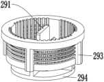
- Figure 6 is a perspective view of the diverter filter of the present invention from one perspective.
- Figure 7 is a perspective view of the diverter filter of the present invention from another perspective.
- Figure 8 is a perspective view of the elbow and elbow sealing sleeve of the present invention.
- connection should be understood in a broad sense.
- it can be a fixed connection, a detachable connection, or an integral body.
- It can be a mechanical connection or an electrical connection; it can be a direct connection or an indirect connection through an intermediate medium; it can be an internal connection between two elements or an interaction between two elements.
- the specific meanings of the above terms in the present invention can be understood on a case-by-case basis.
- the term “above” or “below” a first feature of a second feature may include direct contact between the first and second features, or may also include the first and second features. Not in direct contact but through additional characteristic contact between them.
- the terms “above”, “above” and “above” a first feature on a second feature include the first feature being directly above and diagonally above the second feature, or simply mean that the first feature is higher in level than the second feature.
- “Below”, “under” and “under” the first feature is the second feature includes the first feature being directly below and diagonally below the second feature, or simply means that the first feature is less horizontally than the second feature.
- An anti-leakage water inlet pipe assembly as shown in Figures 1-8, includes a valve body 1.
- a shell 2 is provided outside the valve body 1.
- a bellows 4 is provided inside the shell 2.
- the valve body 1 One end of the inner pipe 5 is connected with a second nut 20, and the other end is connected with an inner pipe 5.
- One end of the inner pipe 5 away from the valve body 1 is connected with an elbow 10, and the end of the elbow 10 is equipped with a first nut 11.
- the inner pipe 5 is located in the bellows 4 and has a second chamber 24 between it and the bellows 4.
- the inner pipe 5 is a PVC pipe, and a central pressure-bearing channel 22 is provided in the valve body 1.
- the central pressure-bearing channel 22 is connected to the inside of the inner tube 5, and the inside of the inner tube 5 is connected to the inside of the elbow 10.
- a first chamber 23 is provided in the housing 2.
- the first chamber 23 communicates with the second chamber 24 .
- the second nut 20 is assembled with the faucet assembly, and the elbow 10 and the first nut 11 are assembled on the washing machine. As shown in Figure 3 or 4, when the leakage-proof water inlet assembly works normally, the water flows from left to right. Right flow.
- a valve core assembly 18 is provided in the central pressure-bearing channel 22, and the valve core assembly 18 can move in the central pressure-bearing channel 22.
- One end of the valve core assembly 18 is fixedly connected to a frame 17, and the frame 17
- Expanded cotton 15 is provided inside, and the expanded cotton 15 is connected with the first chamber 23.
- One end of the expanded cotton 15 is provided with a frame 17, and the other end is provided with a base 16.
- the expanded cotton 15 connected to the first chamber 23 absorbs water and expands.
- One end of the expanded expanded cotton 15 conflicts with the base 16, and the other end conflicts with the frame 17, so that the base
- the relative displacement between 16 and the frame 17 causes the frame 17 to move to the right, and then the valve core assembly 18 fixedly connected to the frame 17 moves to the right.
- valve core assembly 18 is provided with a second sealing ring 21, and the valve body 1 is provided with a slope 25.
- the second sealing ring 21 and the valve The inclined surface 25 in the body 1 contacts and seals to cut off the communication between the central pressure channel 22 and the faucet assembly, thereby cutting off the water flow and preventing water leakage.
- a diverter filter 29 is connected to the interior of one end of the valve body 1 close to the second nut 20.
- the diverter filter 29 includes a filter 292 and a diverter plate 291 provided on the filter 292, so A number of supporting ribs 293 are provided on the outside of the diverter filter 29, and a bottom plate 294 is provided at the bottom of the diverter filter 29.
- the shunt filter 29 is used to guide the water flow from the side of the valve core assembly 18 to prevent the water flow from directly impacting the valve core assembly 18 below, causing the water inlet assembly to self-lock; the support ribs 293 can prevent the shunt filter 29 from Deformation occurs to avoid deformation caused by the shunt filter 29 being soft when its plastic material is not completely cooled and causing the filter 292 to be squeezed together when the shunt filter 29 is just ejected from the mold.
- an aluminum sealing tube 7 is provided between the valve body 1 and the inner tube 5 .
- the aluminum sealing tube 7 makes the connection between the valve body 1 and the inner tube 5 tighter and prevents leakage in the inner tube 5 . Water leaks.
- the elbow 10 is connected to the bellows 4 through a clamp 8 and a buckle 9.
- An aluminum sealing tube 7 is also provided between the elbow 10 and the inner tube 5; between the elbow 10 and the bellows 4
- An elbow sealing sleeve 26 is provided.
- the elbow sealing sleeve 26 is provided with an elbow sealing ring slope 32 on one side close to the housing 2.
- the elbow 10 is provided with a slope on one side close to the inner tube 5. 31.
- the elbow sealing sleeve 26 is put on the elbow pipe 10 and then stuffed into the bellows 4.
- the elbow sealing sleeve 26 plays a sealing role between the elbow pipe 10 and the bellows 4.
- the elbow sealing ring slope 32 is provided.
- the elbow sealing sleeve 26 is easily inserted into the bellows 4, so that the elbow sealing sleeve 26 can achieve a tight sealing effect and prevent water leakage; the slope 31 with bevels and rounded corners provided on the elbow 10 can increase the wall at the rear of the elbow 10 Thick, increase strength, increase the force required to resist breaking, and avoid breakage.
- an elbow gasket 12 is provided in the first nut 11 , a notch 27 is provided at the end of the elbow 10 , and the elbow gasket 12 is embedded in the notch 27 .
- the elbow gasket 12 is first put on the end of the elbow 10 and then the first nut 11 is installed. The elbow gasket 12 is caught by the notch 27 to prevent it from falling.
- a groove 33 is provided on the valve body 1, and a first sealing ring 3 is embedded between the housing 2 and the groove 33 of the valve body 1.
- the first sealing ring 3 is used for The first chamber 23 is sealed to prevent water in the first chamber 23 from leaking.
- the first sealing ring 3 can play a sealing role.
- the groove 33 provided can effectively prevent the first sealing ring 3 from being flushed out under high internal water pressure, thereby improving the first sealing
- the required pressure for the ring 3 to rush out of the housing 2 can effectively prevent the first sealing ring 3 from coming out.
- the second nut 20 is clamped on the valve body 1, and a rubber pad 19 is provided inside the second nut 20.
- the rubber pad 19 conflicts with the side end disk surface of the valve body 1;
- the second nut 20 is also provided with an inner buckle 28.
- the inner buckle 28 is located between the second nut 20 and the valve body 1 and is in contact with the valve body 1; the second nut 20 is provided with a step 30.
- the inner buckle 28 cooperates with the step 30 .
- the inner buckle 28 is used to connect the second nut 20 and the valve body 1, and the inner buckle 28 is locked to prevent the second nut 20 from falling. After the inner buckle 28 is inserted into the second nut 20, the step 30 provided by the second nut 20 makes the inner buckle 28 open and unable to escape from the second nut 20.
- the inner buckle 28 is fixed on the step 30. It will not slide down, and the risk of the inner buckle 28 falling out will also be eliminated.
- the inner buckle 28 and the second nut 20 are made of plastic. Since the plastic parts will shrink inward after being released from the mold, the inner buckle 28 is set in a C shape and will be enlarged during design. The diameter of the inner buckle 28 is such that the inner buckle 28 will exactly meet the required size after shrinking; install the inner buckle 28 on the valve body 1 and manually tighten the second nut 10.
- a sealing sleeve 6 is provided between the housing 2 and the bellows 4 .
- the sealing sleeve 6 is used to seal the first chamber 23 to prevent water entering the first chamber 23 from leaking.
- a sight glass 13 is provided at the bottom end of the housing 2 , and a sight glass sealing ring 14 is provided between the sight glass 13 and the housing 2 .
- the second nut 20 is assembled with the faucet assembly, and the elbow 10 and the first nut 11 are assembled on the washing machine.
- the faucet When the faucet is turned on and water flows into the valve body 1, it flows into the inside of the inner tube 5 from the gap between the valve core assembly 18 and the inner wall of the valve body 1, that is, the central pressure-bearing channel 22, and then flows into the inner tube 5 from the inside of the inner tube 5 and the inner wall of the valve body 1.
- the inside of the elbow pipe 10 enters the washing machine.
- the expanded cotton 15 absorbs water and expands.
- One end of the expanded expanded cotton 15 conflicts with the base 16, and the other end conflicts with the frame 17, so that the base 16 and the frame 17 are relatively displaced, causing the frame 17 to move to the right, and then fixed to the frame 17.
- the connected valve core assembly 18 moves to the right.
- the second sealing ring 21 contacts and seals with the slope 25 in the valve body 1 to cut off the connection between the central pressure channel 22 and the faucet assembly.
- the frame 17 moves to the right, the color of the frame 17 is red, and the sight glass 13 shows red when viewed from outside the valve body 1.
- the normal sight glass is transparent, indicating that the anti-leakage water pipe assembly enters self-locking status, at this time, new water pipes need to be replaced in time.
Landscapes
- Engineering & Computer Science (AREA)
- General Engineering & Computer Science (AREA)
- Mechanical Engineering (AREA)
- Details Of Valves (AREA)
Abstract
一种防泄漏进水管组件,包括阀体(1),阀体(1)外套设有壳体(2),壳体(2)内设置有波纹管(4),阀体(1)的一端套设有第二螺母(20),另一端连接有内管(5),内管(5)背离阀体(1)的一端连接有弯管(10),弯管(10)的端头套设有第一螺母(11)。阀芯组件(18)向右移动时,第二密封圈(21)与阀体(1)内的斜面(25)接触密封,以截断中心承压通道(22)与水龙头组件之间的连通,从而切断水流;并且该防泄漏进水管组件与洗衣机、洗碗机等设备连接处使用的是第一螺母和第二螺母,只需手工扣在阀体上,结构简单,操作便捷,制作成本低,能够满足防泄漏进水管组件批量制作的需求。
Description
本发明涉及一种防泄漏进水管组件,属于家用电器技术领域。
现有的洗衣机、洗碗机等家用电器中的进水管使用时间久了之后容易漏水,甚至会发生水管破裂导致房间内出现积水。而这种水管无法实现自锁水功能,一旦发生破裂或漏水,无法及时切断水流,水会从破裂处源源不断地泄漏,不但会浪费大量的水资源,还会使房间内充满积水,给用户造成不小的经济损失。此外,现有的防泄漏进水管组件与洗衣机、洗碗机等设备连接处使用的第一螺母都是铆压扣在防泄漏进水管组件的阀体上,此种铆压的方式效率低,成本高,无法满足防泄漏进水管组件批量制作的需求。
实用新型内容
为解决上述技术问题,本发明提供了一种防泄漏进水管组件,该防泄漏进水管组件能够在内管发生破裂的情况下,及时切断水流,有效防止水泄漏;并且该防泄漏进水管组件与洗衣机、洗碗机等设备连接处使用的第一螺母为第二螺母,只需手工扣在阀体上,结构简单,操作便捷,制作成本低,能够满足防泄漏进水管组件批量制作的需求。
所述防泄漏进水管组件包括阀体,所述阀体外套设有壳体,所述壳体内设置有波纹管,所述阀体的一端套设有第二螺母,另一端连接有内管,所述内管背离阀体的一端连接有弯管,所述弯管的端头套设有第一螺母。
在本发明的一种实施方式中,所述内管位于所述波纹管内且与波纹管之间设有第二腔室,所述内管为空心管,所述阀体内设有中心承压通道,所述中心承压通道与所述内管的内部连通,所述内管的内部与所述弯管的内部连通,所述壳体内设置有第一腔室,所述第一腔室与所述第二腔室连通。
在本发明的一种实施方式中,所述中心承压通道内设置有阀芯组件,所述阀芯组件能够在中心承压通道内移动,阀芯组件的一端固定连接有框架,所述框架内设置有膨胀棉,所述膨胀棉与所述第一腔室连通,膨胀棉的一端设置有框架,另一端设置有底座。
在本发明的一种实施方式中,所述阀体靠近所述第二螺母一端的内部连接有分流滤网,所述分流滤网包括滤网以及设置在所述滤网上的分流板,所述分流滤网的外侧设置有若干个支撑筋,分流滤网的底部设置有底板,所述底板与所述阀体的内壁之间具有间隙,水流经过所述分流板分流后从所述分流滤网透过,并从所述底板与所述阀体的内壁之间的间隙流入到 所述中心承压通道内。
在本发明的一种实施方式中,所述阀体与所述内管之间还设置有铝封管;所述弯管通过卡箍和卡扣与所述波纹管连接,弯管与内管之间也设置有铝封管;弯管与波纹管之间设置有弯头密封套,所述弯头密封套靠近所述壳体的一侧设置有弯头密封圈斜面,所述弯管靠近所述内管的一侧设置有斜坡。
在本发明的一种实施方式中,所述第一螺母内设置有弯头垫片,所述弯管的端部设置有槽口,所述弯头垫片嵌设在所述槽口内。
在本发明的一种实施方式中,所述阀体上开设有凹槽,所述壳体与所述阀体的凹槽之间嵌设有第一密封圈,所述阀芯组件外套设有第二密封圈,所述阀体内设置有斜面。
在本发明的一种实施方式中,所述第二螺母卡接在所述阀体上,第二螺母内设有橡胶垫,所述橡胶垫与所述阀体的侧端盘面相抵触;所述第二螺母内还设置有内扣,所述内扣位于第二螺母与阀体之间且与阀体相抵接;所述第二螺母内设置有台阶,所述内扣与所述台阶相配合。
在本发明的一种实施方式中,所述第二螺母和所述内扣的材质为塑料。
在本发明的一种实施方式中,所述壳体与所述波纹管之间设置有密封套,所述壳体的底端设置有视镜,所述视镜与所述壳体之间设置有视镜密封圈。
1、本发明能够在内管发生破裂的情况下,及时切断水流,有效防止水泄漏;并且该防泄漏进水管组件与洗衣机、洗碗机等设备连接处使用的第一螺母为第二螺母,只需手工扣在阀体上,结构简单,操作便捷,制作成本低,能够满足防泄漏进水管组件批量制作的需求。
2、本发明的阀芯组件向右移动时,所述第二密封圈与阀体内的斜面接触密封,以截断中心承压通道与水龙头组件之间的连通,从而切断水流,防止水泄漏。
3、本发明的铝封管使阀体与内管之间连接更加紧密,防止内管内的水泄漏。
4、本发明的壳体与阀体之间设置有第一密封圈,所述第一密封圈用于密封第一腔室,防止第一腔室内的水泄漏;壳体与所述波纹管之间设置有密封套,所述密封套用于密封第一腔室,防止第一腔室内的水泄漏。
5、本发明由于膨胀棉吸水后膨胀,框架向右移动,框架的颜色为红色,从阀体外看到视镜显示红色,正常视镜是透明的,表明防泄漏水管组件进入自锁状态,此时需更换新水管,实用简单,操作便捷,可以及时提醒使用者更换水管。
6、本发明的分流滤网用于引导水流从阀芯组件的侧边流过,避免水流直接冲击下方的阀芯组件,引发进水组件的自锁;通过设置的支撑筋可以防止分流滤网发生变形,避免分流滤 网因其塑料材质未完全冷却时较软而导致分流滤网刚出模具顶出时滤网挤压在一起而产生变形。
7、本发明的第二螺母内设置有台阶,所述内扣与所述台阶相配合;内扣套入第二螺母后,第二螺母设置的台阶使内扣撑开无法从第二螺母内脱出,在安装完橡胶垫后,内扣被固定在台阶上,不会向下滑动,也杜绝内扣掉落脱出的风险,所述内扣和第二螺母的材质均为塑料,由于塑料件出模后会出现向内收缩的情况,将所述内扣设置呈C型,设计时会加大内扣的直径,使内扣收缩后会正好符合要求的尺寸;在阀体1装上内扣,手动扣上第二螺母即可
图1为本发明防泄漏进水管组件的立体图。
图2为本发明防泄漏进水管组件又一个视角的立体图。
图3为本发明防泄漏进水管组件的剖视图。
图4为图3中A向的放大图。
图5为图3中B向的放大图。
图6为本发明分流滤网其中一个视角的立体图。
图7为本发明分流滤网另一个视角的立体图。
图8为本发明弯管和弯头密封套的立体图。
图中,1、阀体;2、壳体;3、第一密封圈;4、波纹管;5、内管;6、密封套;7、铝封管;8、卡箍;9、卡扣;10、弯管;11、第一螺母;12、弯头垫片;13、视镜;14、视镜密封圈;15、膨胀棉;16、底座;17、框架;18、阀芯组件;19、橡胶垫;20、第二螺母;21、第二密封圈;21、第二密封圈;22、中心承压通道;23、第一腔室;24、第二腔室;25、斜面;26、弯头密封套;27、槽口;28、内扣;29、分流滤网;291、分流板;292、滤网;293、支撑筋;294、底板;30、台阶;31、斜坡;32、弯头密封圈斜面;33、凹槽。
下面结合附图和实施例对本发明作进一步的详细说明。可以理解的是,此所描述的具体实施例仅仅用于解释本发明,而非对本发明的限定。另外还需要说明的是,为了便于描述,附图中仅示出了与本发明相关的部分而非全部结构。
在本发明的描述中,除非另有明确的规定和限定,术语“相连”、“连接”、“固定”应做广义理解,例如,可以是固定连接,也可以是可拆卸连接,或成一体;可以是机械连接,也可以是电连接;可以是直接相连,也可以通过中间媒介间接相连,可以是两个元件内部的连通或两个元件的相互作用关系。对于本领域的普通技术人员而言,可以具体情况理解上述术语在本发明中的具体含义。
在本发明中,除非另有明确的规定和限定,第一特征在第二特征之“上”或之“下”可以包括第一和第二特征直接接触,也可以包括第一和第二特征不是直接接触而是通过它们之间的另外的特征接触。而且,第一特征在第二特征“之上”、“上方”和“上面”包括第一特征在第二特征正上方和斜上方,或仅仅表示第一特征水平高度高于第二特征。第一特征在第二特征“之下”、“下方”和“下面”包括第一特征在第二特征正下方和斜下方,或仅仅表示第一特征水平高度小于第二特征。
在本发明的描述中,术语“上”、“下”、“左”、“右”等方位或位置关系为基于附图所示的方位或位置关系,仅是为了便于描述和简化操作,而不是指示或暗示所指的装置或元件必须具有特定的方位、以特定的方位构造和操作,因此不能理解为对本发明的限制。此外,术语“第一”、“第二”仅仅用于在描述上加以区分,并没有特殊的含义。
实施例1
一种防泄漏进水管组件,如图1-8所示,包括阀体1,所述阀体1外套设有壳体2,所述壳体2内设置有波纹管4,所述阀体1的一端套设有第二螺母20,另一端连接有内管5,所述内管5背离阀体1的一端连接有弯管10,所述弯管10的端头套设有第一螺母11,所述内管5位于所述波纹管4内且与波纹管4之间设有第二腔室24,所述内管5为PVC管,所述阀体1内设有中心承压通道22,所述中心承压通道22与所述内管5的内部连通,所述内管5的内部与所述弯管10的内部连通,所述壳体2内设置有第一腔室23,所述第一腔室23与所述第二腔室24连通。所述第二螺母20和水龙头组件进行装配,所述弯管10、第一螺母11装配在洗衣机上,如图3或4所示,所述防泄漏进水管组件正常工作时,水流从左向右流动。
进一步地,所述中心承压通道22内设置有阀芯组件18,所述阀芯组件18能够在中心承压通道22内移动,阀芯组件18的一端固定连接有框架17,所述框架17内设置有膨胀棉15,所述膨胀棉15与所述第一腔室23连通,膨胀棉15的一端设置有框架17,另一端设置有底座16。当所述第一腔室23内通水时,与第一腔室23连通的膨胀棉15吸水膨胀,膨胀的膨胀棉15的一端与底座16相抵触,另一端与框架17相抵触,使底座16与框架17发生相对位移,使框架17向右移动,继而使与框架17固定连接的阀芯组件18向右移动。
进一步地,所述阀芯组件18外套设有第二密封圈21,所述阀体1内设置有斜面25,当所述阀芯组件18向右移动时,所述第二密封圈21与阀体1内的斜面25接触密封,以截断中心承压通道22与水龙头组件之间的连通,从而切断水流,防止水泄漏。
进一步地,所述阀体1靠近所述第二螺母20一端的内部连接有分流滤网29,所述分流滤网29包括滤网292以及设置在所述滤网292上的分流板291,所述分流滤网29的外侧设置有若干个支撑筋293,分流滤网29的底部设置有底板294,所述底板294与所述阀体1的 内壁之间具有间隙,水流经过所述分流板291分流后从所述分流滤网29透过,并从所述底板294与所述阀体1的内壁之间的间隙流入到所述中心承压通道22内。分流滤网29用于引导水流从阀芯组件18的侧边流过,避免水流直接冲击下方的阀芯组件18,引发进水组件的自锁;通过设置的支撑筋293可以防止分流滤网29发生变形,避免分流滤网29因其塑料材质未完全冷却时较软而导致分流滤网29刚出模具顶出时滤网292挤压在一起而产生变形。
进一步地,所述阀体1与所述内管5之间还设置有铝封管7,所述铝封管7使阀体1与内管5之间连接更加紧密,防止内管5内的水泄漏。
进一步地,所述弯管10通过卡箍8和卡扣9与所述波纹管4连接,弯管10与内管5之间也设置有铝封管7;弯管10与波纹管4之间设置有弯头密封套26,所述弯头密封套26靠近所述壳体2的一侧设置有弯头密封圈斜面32,所述弯管10靠近所述内管5的一侧设置有斜坡31。其中,弯管10套上弯头密封套26后塞进所述波纹管4内,弯头密封套26起到弯管10和波纹管4之间的密封作用,设置的弯头密封圈斜面32使得弯头密封套26容易插入波纹管4内,可使得弯头密封套26实现紧密的密封作用,防止漏水;弯管10设置的具有斜面和圆角的斜坡31可以增加弯管10尾部的壁厚,增加强度,提高抗折断需要的力,避免出现断裂的情况。
进一步地,所述第一螺母11内设置有弯头垫片12,所述弯管10的端部设置有槽口27,所述弯头垫片12嵌设在所述槽口27内。在弯管10的端部先套上弯头垫片12后再装入第一螺母11,弯头垫片12被所述槽口27卡住,以防止掉落。
进一步地,所述阀体1上开设有凹槽33,所述壳体2与所述阀体1的凹槽33之间嵌设有第一密封圈3,所述第一密封圈3用于密封第一腔室23,防止第一腔室23内的水泄漏。阀体1与壳体2安装到位后第一密封圈3即可起到密封的作用,通过设置的凹槽33可以有效防止第一密封圈3在内部高水压下冲出,提高第一密封圈3冲出壳体2外的所需的压力,能够有效防止第一密封圈3脱出。
进一步地,所述第二螺母20卡接在所述阀体1上,第二螺母20内设有橡胶垫19,所述橡胶垫19与所述阀体1的侧端盘面相抵触;所述第二螺母20内还设置有内扣28,所述内扣28位于第二螺母20与阀体1之间且与阀体1相抵接;所述第二螺母20内设置有台阶30,所述内扣28与所述台阶30相配合。所述内扣28用于连接第二螺母20和阀体1,扣住内扣28后防止第二螺母20掉落。内扣28套入第二螺母20后,第二螺母20设置的台阶30使内扣28撑开无法从第二螺母20内脱出,在安装完橡胶垫19后,内扣28被固定在台阶30上,不会向下滑动,也杜绝内扣28掉落脱出的风险。可选地,所述内扣28和第二螺母20的材质均为塑料,由于塑料件出模后会出现向内收缩的情况,将所述内扣28设置呈C型,设计时会 加大内扣28的直径,使内扣28收缩后会正好符合要求的尺寸;在阀体1上装上内扣28,手动扣上第二螺母10即可。
进一步地,所述壳体2与所述波纹管4之间设置有密封套6,所述密封套6用于密封第一腔室23,防止进入第一腔室23内的水泄漏。
进一步地,所述壳体2的底端设置有视镜13,所述视镜13与所述壳体2之间设置有视镜密封圈14。
本发明工作原理:第二螺母20和水龙头组件进行装配,弯管10、第一螺母11装配在洗衣机上。拧开水龙头,水流入阀体1内时,从阀芯组件18与阀体1的内壁之间的间隙即中心承压通道22,流入到内管5的内部,再从内管5的内部和弯管10的内部进入洗衣机内。
如果内管5破裂,水将流入到内管5和波纹管4的夹层即第二腔室24,第二腔室24内的水流到第一腔室23内,与第一腔室23连通的膨胀棉15吸水膨胀,膨胀的膨胀棉15的一端与底座16相抵触,另一端与框架17相抵触,使底座16与框架17发生相对位移,使框架17向右移动,继而使与框架17固定连接的阀芯组件18向右移动,当阀芯组件18向右移动时,所述第二密封圈21与阀体1内的斜面25接触密封,以截断中心承压通道22与水龙头组件之间的连通,从而切断水流,防止水泄漏。并且由于膨胀棉15吸水后膨胀,框架17向右移动,框架17的颜色为红色,从阀体1外看到视镜13显示红色,正常视镜是透明的,表明防泄漏水管组件进入自锁状态,此时需及时更换新水管。
本发明的保护范围并不仅局限于上述实施例,凡是在本发明构思的精神和原则之内,本领域的专业人员能够做出的任何修改、等同替换和改进等均应包含在本发明的保护范围之内。
Claims (10)
- 一种防泄漏进水管组件,其特征在于,包括阀体(1),所述阀体(1)外套设有壳体(2),所述壳体(2)内设置有波纹管(4),所述阀体(1)的一端套设有第二螺母(20),另一端连接有内管(5),所述内管(5)背离阀体(1)的一端连接有弯管(10),所述弯管(10)的端头套设有第一螺母(11)。
- 根据权利要求1所述的防泄漏进水管组件,其特征在于,所述内管(5)位于所述波纹管(4)内且与波纹管(4)之间设有第二腔室(24),所述内管(5)为空心管,所述阀体(1)内设有中心承压通道(22),所述中心承压通道(22)与所述内管(5)的内部连通,所述内管(5)的内部与所述弯管(10)的内部连通,所述壳体(2)内设置有第一腔室(23),所述第一腔室(23)与所述第二腔室(24)连通。
- 根据权利要求2所述的防泄漏进水管组件,其特征在于,所述中心承压通道(22)内设置有阀芯组件(18),所述阀芯组件(18)能够在中心承压通道(22)内移动,阀芯组件(18)的一端固定连接有框架(17),所述框架(17)内设置有膨胀棉(15),所述膨胀棉(15)与所述第一腔室(23)连通,膨胀棉(15)的一端设置有框架(17),另一端设置有底座(16)。
- 根据权利要求3所述的防泄漏进水管组件,其特征在于,所述阀体(1)靠近所述第二螺母(20)一端的内部连接有分流滤网(29),所述分流滤网(29)包括滤网(292)以及设置在所述滤网(292)上的分流板(291),所述分流滤网(29)的外侧设置有若干个支撑筋(293),分流滤网(29)的底部设置有底板(294),所述底板(294)与所述阀体(1)的内壁之间具有间隙,水流经过所述分流板(291)分流后从所述分流滤网(29)透过,并从所述底板(294)与所述阀体(1)的内壁之间的间隙流入到所述中心承压通道(22)内。
- 根据权利要求4所述的防泄漏进水管组件,其特征在于,所述阀体(1)与所述内管(5)之间还设置有铝封管(7);所述弯管(10)通过卡箍(8)和卡扣(9)与所述波纹管(4)连接,弯管(10)与内管(5)之间也设置有铝封管(7);弯管(10)与波纹管(4)之间设置有弯头密封套(26),所述弯头密封套(26)靠近所述壳体(2)的一侧设置有弯头密封圈斜面(32),所述弯管(10)靠近所述内管(5)的一侧设置有斜坡(31)。
- 根据权利要求5所述的防泄漏进水管组件,其特征在于,所述第一螺母(11)内设置有弯头垫片(12),所述弯管(10)的端部设置有槽口(27),所述弯头垫片(12)嵌设在所述槽口(27)内。
- 根据权利要求6所述的防泄漏进水管组件,其特征在于,所述阀体(1)上开设有凹槽(33),所述壳体(2)与所述阀体(1)的凹槽(33)之间嵌设有第一密封圈(3),所述阀芯组件(18)外套设有第二密封圈(21),所述阀体(1)内设置有斜面(25)。
- 根据权利要求7所述的防泄漏进水管组件,其特征在于,所述第二螺母(20)卡接在所述阀体(1)上,第二螺母(20)内设有橡胶垫(19),所述橡胶垫(19)与所述阀体(1)的侧端盘面相抵触;所述第二螺母(20)内还设置有内扣(28),所述内扣(28)位于第二螺母(20)与阀体(1)之间且与阀体(1)相抵接;所述第二螺母(20)内设置有台阶(30),所述内扣(28)与所述台阶(30)相配合。
- 根据权利要求8所述的防泄漏进水管组件,其特征在于,所述第二螺母(20)和所述内扣(28)的材质为塑料。
- 根据权利要求9所述的防泄漏进水管组件,其特征在于,所述壳体(2)与所述波纹管(4)之间设置有密封套(6),所述壳体(2)的底端设置有视镜(13),所述视镜(13)与所述壳体(2)之间设置有视镜密封圈(14)。
Priority Applications (2)
| Application Number | Priority Date | Filing Date | Title |
|---|---|---|---|
| EP22857078.4A EP4357656A4 (en) | 2022-09-09 | 2022-11-22 | Leakage-proof water intake pipe assembly |
| US18/173,281 US12037735B2 (en) | 2022-09-09 | 2023-02-23 | Anti leakage water inlet pipe assembly |
Applications Claiming Priority (2)
| Application Number | Priority Date | Filing Date | Title |
|---|---|---|---|
| CN202222407516.0U CN218152925U (zh) | 2022-09-09 | 2022-09-09 | 一种防泄漏进水管组件 |
| CN202222407516.0 | 2022-09-09 |
Related Child Applications (1)
| Application Number | Title | Priority Date | Filing Date |
|---|---|---|---|
| US18/173,281 Continuation US12037735B2 (en) | 2022-09-09 | 2023-02-23 | Anti leakage water inlet pipe assembly |
Publications (1)
| Publication Number | Publication Date |
|---|---|
| WO2024050976A1 true WO2024050976A1 (zh) | 2024-03-14 |
Family
ID=84559918
Family Applications (1)
| Application Number | Title | Priority Date | Filing Date |
|---|---|---|---|
| PCT/CN2022/133504 Ceased WO2024050976A1 (zh) | 2022-09-09 | 2022-11-22 | 一种防泄漏进水管组件 |
Country Status (2)
| Country | Link |
|---|---|
| CN (1) | CN218152925U (zh) |
| WO (1) | WO2024050976A1 (zh) |
Citations (8)
| Publication number | Priority date | Publication date | Assignee | Title |
|---|---|---|---|---|
| JPH04160280A (ja) * | 1990-10-23 | 1992-06-03 | Toto Ltd | ボールタップ |
| CN201268799Y (zh) * | 2008-07-25 | 2009-07-08 | 顾年东 | 洗衣机用防逆流进水管组件 |
| CN103032614A (zh) * | 2012-12-29 | 2013-04-10 | 无锡市金华电器控制设备厂 | 一种防泄漏进水管组件的膨胀件 |
| CN203809892U (zh) * | 2014-03-25 | 2014-09-03 | 无锡市金华电器控制设备厂 | 一种防泄漏密封进水管 |
| CN105782611A (zh) * | 2016-04-21 | 2016-07-20 | 无锡市金华屹圆科技有限公司 | 防泄漏进水管结构 |
| CN205655009U (zh) * | 2016-04-21 | 2016-10-19 | 无锡市金华屹圆科技有限公司 | 一种防泄漏进水管结构 |
| CN211398582U (zh) * | 2019-07-01 | 2020-09-01 | 青岛海尔洗衣机有限公司 | 一种水龙头结构及洗衣机 |
| KR20210001256U (ko) * | 2019-11-28 | 2021-06-07 | 최영호 | 수도 부동 급수전의 개폐장치 |
-
2022
- 2022-09-09 CN CN202222407516.0U patent/CN218152925U/zh active Active
- 2022-11-22 WO PCT/CN2022/133504 patent/WO2024050976A1/zh not_active Ceased
Patent Citations (8)
| Publication number | Priority date | Publication date | Assignee | Title |
|---|---|---|---|---|
| JPH04160280A (ja) * | 1990-10-23 | 1992-06-03 | Toto Ltd | ボールタップ |
| CN201268799Y (zh) * | 2008-07-25 | 2009-07-08 | 顾年东 | 洗衣机用防逆流进水管组件 |
| CN103032614A (zh) * | 2012-12-29 | 2013-04-10 | 无锡市金华电器控制设备厂 | 一种防泄漏进水管组件的膨胀件 |
| CN203809892U (zh) * | 2014-03-25 | 2014-09-03 | 无锡市金华电器控制设备厂 | 一种防泄漏密封进水管 |
| CN105782611A (zh) * | 2016-04-21 | 2016-07-20 | 无锡市金华屹圆科技有限公司 | 防泄漏进水管结构 |
| CN205655009U (zh) * | 2016-04-21 | 2016-10-19 | 无锡市金华屹圆科技有限公司 | 一种防泄漏进水管结构 |
| CN211398582U (zh) * | 2019-07-01 | 2020-09-01 | 青岛海尔洗衣机有限公司 | 一种水龙头结构及洗衣机 |
| KR20210001256U (ko) * | 2019-11-28 | 2021-06-07 | 최영호 | 수도 부동 급수전의 개폐장치 |
Also Published As
| Publication number | Publication date |
|---|---|
| CN218152925U (zh) | 2022-12-27 |
Similar Documents
| Publication | Publication Date | Title |
|---|---|---|
| WO2018129742A1 (zh) | 滤芯组件和具有其的净水器 | |
| WO2024050976A1 (zh) | 一种防泄漏进水管组件 | |
| WO2022078135A1 (zh) | 一种用于低压工况的单向阀 | |
| US12037735B2 (en) | Anti leakage water inlet pipe assembly | |
| CN214695881U (zh) | 一种应用在泵闸上通过单向泵实现双向抽水功能的装置 | |
| CN216742848U (zh) | 截止阀 | |
| CN215061348U (zh) | 一种煤气阀检测泄漏自动关闭装置 | |
| CN211355319U (zh) | 一种分水调节装置及洗碗机 | |
| CN211398848U (zh) | 空调用连接结构及空调 | |
| CN221857635U (zh) | 一种止回阀及电器设备 | |
| CN214222285U (zh) | 冷凝器管路连接接头 | |
| CN220452770U (zh) | 一种球阀 | |
| CN220151959U (zh) | 一种气密性单向阀 | |
| CN207999893U (zh) | 空调制冷剂的防泄漏装置 | |
| CN215172249U (zh) | 一种多功能洗衣机水龙头 | |
| CN223412256U (zh) | 热水机 | |
| CN215157552U (zh) | 密封冲洗水缓冲罐 | |
| CN206338515U (zh) | 安全注水接头及洗衣机 | |
| CN217634448U (zh) | 一种防泄漏进水管组件 | |
| CN223609431U (zh) | 一种便携式通用气嘴 | |
| CN221257671U (zh) | 自带止水结构的角阀 | |
| CN223814453U (zh) | 一种高密封性的水冷接头 | |
| CN218582566U (zh) | 新型gis抽真空管路多用接头 | |
| CN222722943U (zh) | 一种喷淋装置及洗碗机 | |
| CN223104808U (zh) | 一种动力装置及具有其的烟机 |
Legal Events
| Date | Code | Title | Description |
|---|---|---|---|
| ENP | Entry into the national phase |
Ref document number: 2022857078 Country of ref document: EP Effective date: 20230223 |
|
| 121 | Ep: the epo has been informed by wipo that ep was designated in this application |
Ref document number: 22857078 Country of ref document: EP Kind code of ref document: A1 |
|
| NENP | Non-entry into the national phase |
Ref country code: DE |