WO2024052978A1 - 状態検出システム、方法、およびプログラム - Google Patents
状態検出システム、方法、およびプログラム Download PDFInfo
- Publication number
- WO2024052978A1 WO2024052978A1 PCT/JP2022/033385 JP2022033385W WO2024052978A1 WO 2024052978 A1 WO2024052978 A1 WO 2024052978A1 JP 2022033385 W JP2022033385 W JP 2022033385W WO 2024052978 A1 WO2024052978 A1 WO 2024052978A1
- Authority
- WO
- WIPO (PCT)
- Prior art keywords
- external force
- milling tool
- force
- load torque
- shaft portion
- Prior art date
- Legal status (The legal status is an assumption and is not a legal conclusion. Google has not performed a legal analysis and makes no representation as to the accuracy of the status listed.)
- Ceased
Links
Images










Classifications
-
- B—PERFORMING OPERATIONS; TRANSPORTING
- B23—MACHINE TOOLS; METAL-WORKING NOT OTHERWISE PROVIDED FOR
- B23C—MILLING
- B23C9/00—Details or accessories so far as specially adapted to milling machines or cutter
-
- B—PERFORMING OPERATIONS; TRANSPORTING
- B23—MACHINE TOOLS; METAL-WORKING NOT OTHERWISE PROVIDED FOR
- B23Q—DETAILS, COMPONENTS, OR ACCESSORIES FOR MACHINE TOOLS, e.g. ARRANGEMENTS FOR COPYING OR CONTROLLING; MACHINE TOOLS IN GENERAL CHARACTERISED BY THE CONSTRUCTION OF PARTICULAR DETAILS OR COMPONENTS; COMBINATIONS OR ASSOCIATIONS OF METAL-WORKING MACHINES, NOT DIRECTED TO A PARTICULAR RESULT
- B23Q17/00—Arrangements for observing, indicating or measuring on machine tools
- B23Q17/09—Arrangements for observing, indicating or measuring on machine tools for indicating or measuring cutting pressure or for determining cutting-tool condition, e.g. cutting ability, load on tool
- B23Q17/0952—Arrangements for observing, indicating or measuring on machine tools for indicating or measuring cutting pressure or for determining cutting-tool condition, e.g. cutting ability, load on tool during machining
- B23Q17/0966—Arrangements for observing, indicating or measuring on machine tools for indicating or measuring cutting pressure or for determining cutting-tool condition, e.g. cutting ability, load on tool during machining by measuring a force on parts of the machine other than a motor
-
- G—PHYSICS
- G01—MEASURING; TESTING
- G01L—MEASURING FORCE, STRESS, TORQUE, WORK, MECHANICAL POWER, MECHANICAL EFFICIENCY, OR FLUID PRESSURE
- G01L1/00—Measuring force or stress, in general
- G01L1/20—Measuring force or stress, in general by measuring variations in ohmic resistance of solid materials or of electrically-conductive fluids; by making use of electrokinetic cells, i.e. liquid-containing cells wherein an electrical potential is produced or varied upon the application of stress
- G01L1/22—Measuring force or stress, in general by measuring variations in ohmic resistance of solid materials or of electrically-conductive fluids; by making use of electrokinetic cells, i.e. liquid-containing cells wherein an electrical potential is produced or varied upon the application of stress using resistance strain gauges
- G01L1/225—Measuring circuits therefor
- G01L1/2256—Measuring circuits therefor involving digital counting
-
- G—PHYSICS
- G05—CONTROLLING; REGULATING
- G05B—CONTROL OR REGULATING SYSTEMS IN GENERAL; FUNCTIONAL ELEMENTS OF SUCH SYSTEMS; MONITORING OR TESTING ARRANGEMENTS FOR SUCH SYSTEMS OR ELEMENTS
- G05B19/00—Program-control systems
- G05B19/02—Program-control systems electric
- G05B19/18—Numerical control [NC], i.e. automatically operating machines, in particular machine tools, e.g. in a manufacturing environment, so as to execute positioning, movement or co-ordinated operations by means of program data in numerical form
- G05B19/406—Numerical control [NC], i.e. automatically operating machines, in particular machine tools, e.g. in a manufacturing environment, so as to execute positioning, movement or co-ordinated operations by means of program data in numerical form characterised by monitoring or safety
- G05B19/4065—Monitoring tool breakage, life or condition
-
- B—PERFORMING OPERATIONS; TRANSPORTING
- B23—MACHINE TOOLS; METAL-WORKING NOT OTHERWISE PROVIDED FOR
- B23C—MILLING
- B23C2270/00—Details of milling machines, milling processes or milling tools not otherwise provided for
-
- G—PHYSICS
- G05—CONTROLLING; REGULATING
- G05B—CONTROL OR REGULATING SYSTEMS IN GENERAL; FUNCTIONAL ELEMENTS OF SUCH SYSTEMS; MONITORING OR TESTING ARRANGEMENTS FOR SUCH SYSTEMS OR ELEMENTS
- G05B2219/00—Program-control systems
- G05B2219/30—Nc systems
- G05B2219/37—Measurements
- G05B2219/37355—Cutting, milling, machining force
Definitions
- the present disclosure relates to a state detection system, method, and program.
- Patent Document 1 discloses a tool abnormality detection device that detects an abnormality occurring in a tool by using the interrelationship of principal force, feed force, and back force generated during cutting. Disclosed.
- Patent Document 2 discloses abnormal phenomenon monitoring in which chipping is determined by determining the cutting force ratio of principal force, feed force, and back force, and the differential coefficient of the force force ratio with respect to time.
- JP-A-09-076144 (Patent Document 3) describes a machining state monitoring method for detecting loads on the X-axis and Y-axis to monitor the machining state in drilling with a machine tool. ing.
- a state detection system for a milling tool used in milling includes a first end provided with a blade for cutting a workpiece, and a second end attached to a machine tool.
- a milling tool including a shaft portion having a shaft portion and rotatable around a rotation axis of the shaft portion; a plurality of sensors attached to the shaft portion for detecting an external force acting on the milling tool; a display device; a management device; Equipped with The plurality of sensors are configured to apply a first force acting on the milling tool in a first direction along the rotation axis, a second force acting on the milling tool in a direction along a plane normal to the rotation axis, and a second force acting on the milling tool in a first direction along the rotation axis.
- a load torque acting in a direction that prevents rotation of the tool is detected.
- the management device causes the display device to display information based on at least two of the first force, the second force, and the load torque.
- FIG. 1 is a schematic diagram of a state detection system for a milling tool according to the present embodiment.
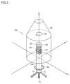
- FIG. 2 is a perspective view of the milling tool.
- FIG. 3 is a diagram of the milling tool in FIG. 2 viewed from the negative side of the Y-axis.
- FIG. 4 is a diagram of the milling tool in FIG. 2 viewed from the positive direction of the X-axis.
- FIG. 5 is a diagram of the shaft portion in FIG. 2 viewed from the positive direction side of the Z-axis.
- FIG. 6 is a diagram of the free end of the shaft portion 106 in FIG. 2 viewed from the positive direction side of the Z-axis.
- FIG. 7 is a diagram showing the relationship between external forces Fx, Fy, Fz and the state of the blade.
- FIG. 8 is a first example of a graph showing the state of the milling tool.
- FIG. 9 is a second example of a graph showing the state of the milling tool.
- FIG. 10 is a third example of a graph showing the state of the milling tool.
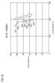
- FIG. 11 is a fourth example of a graph showing the state of the milling tool.
- FIG. 12 is a fifth example of a graph showing the state of the milling tool.
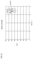
- FIG. 13 is a sixth example of a graph showing the state of the milling tool.
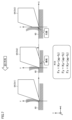
- FIG. 14 explains the relationship between external force, specific cutting resistance, and cutting area.
- FIG. 15 is a diagram for explaining the relationship between load torque and cutting area.
- FIG. 16 is a seventh example of a graph showing the state of the milling tool.
- FIG. 17 is an eighth example of a graph showing the state of the milling tool.
- FIG. 18 is a flowchart showing the processing procedure of this embodiment.
- FIG. 19 is a diagram showing measurement results of a test for creating a normal region.
- FIG. 20 is a diagram displaying a graph based on the measurement results of FIG. 19.
- FIG. 21 is a diagram illustrating an example of setting a normal region in period Dr2.
- FIG. 22 is a diagram illustrating an example of setting normal regions in periods Dr2 and Dr3.
- An object of the present disclosure is to provide a state detection system that detects the state of a milling tool used for milling.
- an external force that is generated on a milling tool acts in a direction along the rotation axis, an external force that acts in a direction along a plane normal to the rotation axis, and a load torque that acts in a direction that prevents rotation. Based on this, it is possible to provide a state detection system capable of detecting the state of a milling tool used for determining abnormality of the milling tool.
- the state detection system for a cutting tool used in milling includes a first end provided with a blade for cutting a workpiece, and a second end attached to a machine tool.
- a milling tool including a shaft portion having a shaft portion and rotatable around a rotation axis of the shaft portion; a plurality of sensors attached to the shaft portion to detect an external force acting on the milling tool; a display device; and a management device.
- the plurality of sensors are configured to apply a first force acting on the milling tool in a first direction along the rotation axis, a second force acting on the milling tool in a direction along a plane normal to the rotation axis, and a second force acting on the milling tool in a first direction along the rotation axis.
- a load torque acting in a direction that prevents rotation of the tool is detected.
- the management device causes the display device to display first information based on at least two of the first force, the second force, and the load torque.
- the management device displays the first information using a graph.
- the management device in addition to the first information, the management device generates second information based on at least two of the first force, the second force, and the load torque. is displayed on the display device.
- the second information is information different from the first information.
- the first information is information based on the ratio of the first force to the load torque and the ratio of the second force to the load torque.
- the plurality of sensors detect strain in the first direction, and include a first strain sensor, a second strain sensor, and a second strain sensor attached to the shaft portion. and a third strain sensor, and a fourth strain sensor that detects strain in the circumferential direction of the shaft portion and is attached to the shaft portion.
- the method according to the present disclosure is a method of detecting the state of a milling tool used for milling.
- the milling tool includes a shaft portion having a first end portion provided with a blade portion for cutting a workpiece and a second end portion attached to a machine tool, and rotates around a rotation axis of the shaft portion.
- a plurality of sensors are attached to the shaft portion to detect external forces acting on the milling tool.
- the method includes the steps of: obtaining a first force acting in a first direction along the rotation axis using detection values of the plurality of sensors; and setting the rotation axis as a normal line using the detection values of the plurality of sensors.
- a step of obtaining a second force acting in a direction along the plane a step of obtaining a load torque acting in a direction that prevents rotation of the milling tool using detection values of the plurality of sensors; a first force; displaying first information based on at least two of the second force and the load torque.
- the program according to the present disclosure is a program that detects the state of a milling tool used for milling.
- the milling tool includes a shaft portion having a first end portion provided with a blade portion for cutting a workpiece and a second end portion attached to a machine tool, and rotates around a rotation axis of the shaft portion.
- a plurality of sensors are attached to the shaft portion to detect external forces acting on the milling tool.
- a step of obtaining a force a step of obtaining a load torque acting in a direction that impedes rotation of the milling tool; and displaying first information based on at least two of the first force, the second force, and the load torque. Execute the steps.
- FIG. 1 is a schematic diagram of a state detection system 100 for a milling tool 50 in this embodiment.
- the state detection system 100 of the milling tool 50 in FIG. 1 can be applied to a milling tool of a machine tool such as a machining center or a milling machine.
- the state detection system 100 includes a management device 10 and a machine tool 70.
- Machine tool 70 includes a motor 20 and a milling tool 50.
- the milling tool 50 is a milling tool that cuts a fixed object to be cut (workpiece), and is a milling tool used in a machine tool such as a machining center or a milling machine.
- the milling tool 50 in this embodiment is an end mill.
- the milling tool 50 may be a milling tool other than an end mill, such as a drill or a milling cutter.
- the milling tool 50 includes a shaft portion 106 in which a cutting portion is formed.
- the milling tool 50 is attached to the machine tool 70 via the tool holder 30 that holds the shaft portion 106 .
- a blade portion is provided at the end of the shaft portion 106 on the lower side in the vertical direction, and the end portion of the shaft portion 106 on the upper side in the vertical direction is attached to the tool holder 30 on the machine tool 70 side.
- the end of the shaft section 106 on the lower side in the vertical direction is an example of the "first end” in the present disclosure
- the end of the shaft section 106 on the upper side in the vertical direction is an example of the "second end” in the present disclosure. ” is an example.
- the tool holder 30 may be formed at the end of the shaft portion 106 on the upper side in the vertical direction. In that case, the milling tool 50 includes the tool holder 30.
- the tool holder 30 is connected to the shaft portion 106 and supports the shaft portion 106 from above in the vertical direction.
- the tool holder 30 has a conical end on the positive side of the Z axis, and the conical end is attached to the machine tool 70 .
- the motor 20 included in the machine tool 70 rotates the milling tool 50 integrally. In other words, the motor 20 rotates the milling tool 50.
- Motor 20 is, for example, a servo motor.
- the milling tool 50 which is an end mill in this embodiment, has at least one blade portion.
- the blade of the milling tool 50 and the surface of the workpiece come into contact and the surface of the workpiece is scraped off. Thereby, the shape of the work becomes the shape desired by the user.
- the strain sensors N1 to N3, S4 are attached to the shaft portion 106.
- the strain sensors N1 to N3, S4 are sensors capable of detecting strain occurring in the shaft portion 106, and are, for example, strain gauges configured by a bridge circuit.
- the strain sensors N1 to N3, S4 are wirelessly connected to the management device 10, and transmit the values detected by each to the management device 10.
- the management device 10 detects the state of the milling tool 50 using the detected values of strain sensors N1 to N3 and S4 attached to the milling tool 50.
- the management device 10 includes a communication device 210, a CPU (Central Processing Unit) 220 that is a control device, a storage device 230, an input/output interface (I/F) 240, a display device 40, and an input device 270. .
- CPU Central Processing Unit
- I/F input/output interface
- the communication device 210, CPU 220, storage device 230, and input/output I/F 240 are connected to a common bus 250 and are configured to be able to exchange signals with each other.
- the display device 260 and the input device 270 are connected to the input/output I/F 240 by wire or wirelessly.
- the communication device 210 is a wireless communication device, and wirelessly acquires the detected values of the strain sensors N1 to N3 and S4 attached to the tool holder 30.
- the CPU 220 executes a program stored in the storage device 230 and processes the detected values of the strain sensors N1 to N3 and S4 acquired by the communication device 210, thereby detecting the state of the milling tool 50.
- the storage device 230 includes memories such as ROM (Read Only Memory) and RAM (Random Access Memory), as well as memory such as HDD (Hard Disc Drive) or SSD (Solid State Disk). Including mass storage devices.
- the storage device 230 is used as a buffer during processing by the CPU 220, and is also used to store programs executed by the CPU 220, detected values of the strain sensors N1 to N3, S4, and/or calculation results by the CPU 220. It will be done.
- the input device 270 is, for example, a keyboard, a mouse, a trackball, or a pointing device such as a touch panel, and receives operation signals from the user.
- the display device 40 is typically a liquid crystal panel or an organic EL (Electro Luminescence) panel, and displays the calculation results of the CPU 220 and information stored in the storage device 230 to the user.
- the management device 10 allows the user to recognize the state of the milling tool 50 by displaying information based on the detected values of the strain sensors N1 to N3, S4 on the display device 40.
- the input/output I/F 240 is an interface for connecting the display device 40 and the input device 270. Via the input/output I/F 240, it receives a user operation signal from the input device 270, and outputs information to notify the user to the display device 40.
- FIG. 2 is a perspective view of the milling tool 50.
- the Z axis shown in FIG. 2 is the rotation axis of the milling tool 50. That is, the milling tool 50 is rotated about the Z-axis by being driven by the motor 20.
- the milling tool 50 rotates in a clockwise rotation direction Rd when viewed from the positive direction side of the Z-axis.
- the X-axis and Y-axis, which are perpendicular to each other, are also perpendicular to the Z-axis.
- the positive direction of the Z axis in each figure may be referred to as the upper surface side
- the negative direction may be referred to as the lower surface side.
- the rotating milling tool 50 comes into contact with the surface of the workpiece and scrapes the surface of the workpiece.
- an external force acts on the milling tool 50.
- external forces that act on the milling tool 50 due to contact between the milling tool 50 and the workpiece include external forces Fx, Fy, and Fy that act in the X-axis, Y-axis, and Z-axis directions, respectively.
- Fz and a load torque Mz that acts in a direction that prevents rotation of the milling tool 50. Since the load torque Mz acts in a direction that prevents the rotation of the milling tool 50, it acts in a rotation direction opposite to the rotation direction Rd of the milling tool 50. That is, when viewed from the positive direction side of the Z-axis, the load torque Mz acts counterclockwise.
- the direction in which the external force Fx acts is shown as the positive direction of the X-axis
- the direction in which the external force Fy acts is shown as the negative direction of the Y-axis
- the direction in which the external force Fz acts is shown as the negative direction of the Z-axis.
- external force Fx, external force Fy, and external force Fz are marked with different hatching. Note that the external forces Fx, Fy, and Fz may act in a direction opposite to that shown in FIG. 2 in some cases.
- the strain sensors N1 to N3, S4 are arranged on the same XY plane.
- the strain sensors N1 to N3, S4 are arranged on the surface of the shaft portion 106 at intervals of 90° in the circumferential direction of the shaft portion 106. That is, when the shaft portion 106 is viewed from the negative side of the Y-axis, the strain sensor N1 and the strain sensor N3 are arranged line-symmetrically with respect to the Z-axis. Further, when the shaft portion 106 is viewed from the positive side of the X-axis, the strain sensor N2 and the strain sensor S4 are arranged line-symmetrically with respect to the Z-axis.
- the strain sensors N1 to N3 have measurement sensitivity to the strain of the shaft portion 106 in the Z-axis direction.
- the strain sensor S4 has measurement sensitivity for circumferential strain of the shaft portion 106. A method of detecting external forces Fx, Fy, Fz and load torque Mz using strain sensors N1 to N3 and S4 will be described below.
- FIG. 3 is a diagram of the milling tool 50 in FIG. 2 viewed from the negative side of the Y-axis.
- external forces Fx and Fz are shown.
- the shaft portion 106 is a cantilever beam having a fixed end on the positive side of the Z-axis and a free end on the negative side of the Z-axis where the blade portion is formed. Therefore, when the external force Fx acts on the milling tool 50, a bending moment is generated. The magnitude of the bending moment is determined from the magnitude of the external force Fx and the distance D1 between the strain sensors N1, N3 and the free end of the shaft portion 106 in the Z-axis direction.
- the shaft portion 106 Due to the action of the bending moment, the shaft portion 106 is deformed into a slightly warped state so that a convexity is formed on the negative side of the X-axis. That is, the shaft portion 106 is bent by the external force Fx.
- the bending moment generates compressive stress Cx and tensile stress Tx as bending stress depending on the section modulus of the shaft portion 106.
- compressive stress Cx and tensile stress Tx generated by external force Fx are marked with the same hatching as external force Fx.
- the strain sensor N1 disposed on the positive side of the X-axis of the shaft portion 106 has measurement sensitivity with respect to compressive stress Cx.
- the strain sensor N1 also has measurement sensitivity to tensile stress Tz generated by external force Fz.
- the tensile stress Tz generated by the external force Fz is marked with the same hatching as the external force Fz. Therefore, the strain sensor N1 detects the resultant force of the compressive stress Cx and the tensile stress Tz.
- the detected value Dv1 of the strain sensor N1 is the resultant force of the compressive stress Cx and the tensile stress Tz.
- the strain sensor N1 transmits the detected value Dv1 to the management device 10.
- the strain sensor N3 has measurement sensitivity to the tensile stress Tx caused by the external force Fx in addition to the tensile stress Tz caused by the external force Fz. Therefore, the detected value Dv3 of the strain sensor N3 is the resultant force of the tensile stress Tx and the tensile stress Tz. The strain sensor N3 transmits the detected value Dv3 to the management device 10.
- the management device 10 determines the tensile stress Tz, the tensile stress Tx, and the compressive stress Cx from the detected value Dv1 indicating the resultant force of the compressive stress Cx and the tensile stress Tz and the detected value Dv3 indicating the resultant force of the tensile stress Tx and the tensile stress Tz. Calculate each value.
- the strain sensors N1 and N3 are arranged line-symmetrically with respect to the Z axis on the same XY plane, and the compressive stress Cx and the tensile stress Tx are bending stresses generated based on the same bending moment. Compressive stress Cx and tensile stress Tx are stresses of the same magnitude.
- the management device 10 calculates the magnitude of each of the compressive stress Cx and the tensile stress Tx by calculating the difference between the detected value Dv1 and the detected value Dv3.
- the magnitude of each of the compressive stress Cx and the tensile stress Tx changes depending on the bending moment determined from the magnitude of the external force Fx and the distance D1. That is, the management device 10 can calculate the magnitude of the external force Fx from the magnitude of each of the compressive stress Cx and the tensile stress Tx and the distance D1.
- the management device 10 subtracts the magnitude of the compressive stress Cx from the detected value Dv1 or subtracts the magnitude of the tensile stress Tx from the detected value Dv3.
- the magnitude of the tensile stress Tz can also be calculated by any one of these processes. Since the tensile stress Tz is a force generated by the external force Fz, the management device 10 can calculate the magnitude of the external force Fz based on the magnitude of the tensile stress Tz. In this way, the management device 10 calculates the magnitude of the external force Fx and the magnitude of the external force Fz from the detected values Dv1 and Dv3 of the strain sensors N1 and N3.
- FIG. 4 is a diagram of the milling tool 50 in FIG. 2 viewed from the positive side of the X-axis.
- FIG. 4 shows external forces Fy and Fz generated by contact between the milling tool 50 and the workpiece.
- the strain sensor N2 has measurement sensitivity in the Z-axis direction.
- the external force Fy causes the shaft portion 106 to bend to form a convexity in the positive direction of the Y-axis.
- the strain sensor N2 disposed on the positive side of the Y-axis of the shaft portion 106 detects the resultant force of the tensile stress Ty and the tensile stress Tz as a detected value Dv2.
- the management device 10 calculates the magnitude of the tensile stress Tz from the detected values Dv1 and Dv3 of the strain sensors N1 and N3.
- the management device 10 can calculate the magnitude of the tensile stress Ty by subtracting the tensile stress Tz from the detected value Dv2.
- the management device 10 can calculate the magnitude of the external force Fy from the magnitude of the tensile stress Ty and the distance D1 in the same way as calculating the magnitude of the external force Fx.
- FIG. 5 is a diagram of the shaft portion 106 in FIG. 2 viewed from the positive direction side of the Z-axis.
- the strain sensor S4 has measurement sensitivity in the circumferential direction of the tool holder 30. Therefore, when the milling tool 50 comes into contact with the workpiece, a load torque Mz acts on the tool holder 30 in a rotation direction opposite to the rotation direction Rd of the milling tool 50 and the tool holder 30. That is, as long as the rotating milling tool 50 is in contact with the workpiece, the detected value of the strain sensor S4 includes the load torque Mz.
- the detected value of the strain sensor S4 includes at least one of the external force Fx and the external force Fy in addition to the load torque Mz. .
- the arrangement of the strain sensor S4 on the XY plane changes depending on the rotation angle of the tool holder 30.
- the strain sensor S4 in the arrangement Ag1 has measurement sensitivity to the external force Fx because the measurement direction of the strain sensor S4 is parallel to the X-axis direction.
- the strain sensor S4 in the arrangement Ag2 has measurement sensitivity to the external force Fy because the measurement direction of the strain sensor S4 is parallel to the Y-axis direction.
- the strain sensor S4 in the arrangement Ag3 has measurement sensitivity to both the external force Fx and the external force Fy because the measurement direction of the strain sensor S4 intersects both the X-axis direction and the Y-axis direction. Strain sensor S4 detects the resultant force of external force Fx, external force Fy, and load torque Mz.
- the management device 10 calculates the magnitude of the external force Fx and the magnitude of the external force Fy based on the detected values Dv1 to Dv3 of the strain sensors N1 to N3.
- the management device 10 can calculate the load torque Mz by removing the influence of the external force Fx and the external force Fy from the detected value of the strain sensor S4.
- the external forces Fx, Fy, Fz and the load are controlled by strain sensors N1 to N3 having measurement sensitivity in the Z-axis direction and S4 having measurement sensitivity in the circumferential direction of the shaft portion 106.
- the magnitude of torque Mz can be calculated.
- the condition detection system 100 has a configuration including a total of six strain sensors, three strain sensors having measurement sensitivities in the circumferential direction and three strain sensors having measurement sensitivities in the Z-axis direction;
- the configuration may include a total of five strain sensors, including three strain sensors having measurement sensitivity in the Z-axis direction and two strain sensors having measurement sensitivity in the Z-axis direction. In this way, by increasing the number of strain sensors, it is possible to directly detect the load torque Mz, etc., so that in the state detection system 100, the calculation processing performed by the management device 10 can be reduced.
- FIG. 6 is a diagram of the free end of the shaft portion 106 in FIG. 2 viewed from the positive direction side of the Z-axis.
- the milling tool 50 has three blade parts 6A, 6B, and 6C.
- the external forces Fx, Fy, Fz and load torque Mz explained in FIGS. 1 to 5 are generated when each of the blade parts 6A to 6C comes into contact with the workpiece.
- the load torque Mz calculated using the strain sensor S4 is the load torque MzA acting on the blade portion 6A shown in FIG. 6, the load torque MzB acting on the blade portion 6B, and the load acting on the blade portion 6C. This is the resultant force with torque MzC. Since all of the load torques MzA, MzB, and MzC are forces that act in the same circumferential direction, the load torque Mz calculated using the strain sensor S4 is the absolute value of each of the load torques MzA, MzB, and MzC. The value is the sum of the values.
- the external forces Fx and Fy are calculated as the sum of vectors rather than the sum of the absolute values of the external forces generated on each blade part. Therefore, the external forces generated on each blade portion may cancel each other out.
- the resultant force of the external forces Fx and Fy will be referred to as "external force Fxy.”
- external force FxyA acts on the blade portion 6A
- external force FxyB acts on the blade portion 6B
- external force FxyC acts on the blade portion 6C.
- the load torque Mz is actually a value obtained by multiplying the component force in the tangential direction of the external force Fxy by the radius of the milling tool 50, but in FIG. 6, for ease of explanation, the tangential line is The arrow extending from the direction is described as the load torque Mz.
- FIG. 7 is a diagram showing the relationship between the external forces Fx, Fy, and Fz and the state of the blade.
- FIG. 7 shows the blade portion 6A in states St1, St2, and St3, respectively.
- State St1 is a state in which there is no problem with the blade portion 6A and cutting can be performed appropriately.
- State St2 is a state in which the cutting edge of the blade portion 6A is worn.
- State St3 is a state in which the cutting edge of the blade portion 6A is damaged.
- FIG. 7 shows a workpiece 60 being scraped off.
- the external force Fx generated by the contact between the workpiece 60 and the blade portion 6A is determined from the specific cutting resistance Kx and the cutting area.
- the specific cutting resistance Kx is the resistance in the X-axis direction based on the state of the blade.
- the specific cutting resistance has different values in each direction of the X-axis, Y-axis, and Z-axis.
- the cutting area is determined from the cutting depth ap and the feed amount fz.
- the external force Fx is a value obtained by multiplying the specific cutting resistance Kx, the cutting depth ap, and the feed amount fz.
- the external force Fy is a value obtained by multiplying the specific cutting resistance Ky in the Y-axis direction, the cutting depth ap, and the feed amount fz.
- the external force Fz is a value obtained by multiplying the specific cutting resistance Kz indicating the state of the blade portion in the Z-axis direction by the cutting depth ap and the feed amount fz. Since each of the specific cutting forces Kx, Ky, and Kz changes depending on the state of the cutting edge in each axial direction, the values of the specific cutting forces Kx, Ky, and Kz are different from each other.
- FIGS. 8 to 10 show the results of experiments conducted under the following processing conditions.
- the material of the workpiece is carbon steel (S50C).
- the milling tool 50 is a four-blade end mill.
- the tool diameter is ⁇ 6 mm.
- the cutting speed is 60 m/min.
- the feed amount per blade is 0.015 mm/t (tooth).
- the depth of cut in the axial direction is 1 mm.
- the amount of cut in the radial direction is 2.4 mm.
- FIG. 8 is a first example of a graph showing the state of the milling tool 50.
- the vertical axis indicates the external force Fz
- the horizontal axis indicates the external force Fxy.
- plots N11 to N18 are shown. Each of the plots N11 to N18 shows the external force Fz and the external force Fxy at specific timings calculated by the method described in FIGS. 2 to 6.
- Each of the plots N11 to N18 is a value detected during the period in which the milling tool 50 is rotated by the motor 20 to cut the workpiece, and the values are detected in the order of the plots N11 to N18.
- Plot N11 is the value detected at the earliest time
- plot N18 is the value detected at the latest time. That is, the timing at which plot N18 is detected has the largest number of cutting times and the largest cutting time compared to the timing at which other plots are detected. Therefore, at the timing when plot N18 is detected, the wear of the milling tool 50 is more advanced than at the timing when other plots are detected.
- each plot moves toward the upper right on the graph as wear progresses.
- the cutting area is determined independently, regardless of the state of the cutting edge. Furthermore, since the blade repeatedly contacts the workpiece 60, the size of the cutting area may vary each time the blade and the workpiece 60 come into contact. Therefore, even in a state where the wear of the cutting edge has progressed, the external force Fz and the external force Fxy may decrease depending on the size of the cutting area. However, if the tendency of movement from plot N11 to plot N18 is grasped as a whole, each plot moves toward the upper right on the graph.
- the user can estimate the degree of progress of wear based on the direction and amount of movement of the graph plot shown in FIG. 8. That is, the condition detection system can visually display to the user the degree of progress of wear indicating the condition of the milling tool 50. That is, in the state detection system 100 according to the present embodiment, the user can recognize the wear state of the milling tool 50 based on the trend in the moving direction of the plot and the amount of movement. Thereby, the user can easily predict when to replace the milling tool 50.
- FIG. 9 is a second example of a graph showing the state of the milling tool 50.
- the vertical axis shows the external force Fxy
- the horizontal axis shows the load torque Mz.
- plots N21 to N28 are shown. Plots N21 to N28 are detected in the same order as plots N11 to N18. That is, among the plots N21 to N28, the timing at which plot N28 is detected is the timing at which wear is most advanced.
- the state detection system 100 can be used to This allows the user to recognize the state of wear of the milling tool 50.
- FIG. 10 is a third example of a graph showing the state of the milling tool 50.
- the vertical axis indicates external force Fz
- the horizontal axis indicates load torque Mz.
- Plots N31 to N38 are shown in FIG. Plots N31 to N38 are detected in the same order as plots N11 to N18. That is, among the plots N31 to N38, the timing at which plot N38 is detected is the timing at which wear is most advanced. Also in the graph of FIG. 10, as the wear progresses, the external force Fz and the load torque Mz increase, so each plot in FIG. 10 also tends to move toward the upper right on the graph.
- the display device 40 may display the detected abnormality. More specifically, a test machining is performed using a specific milling tool shape and specific machining conditions, and the range in which plots are detected due to wear in the graphs of FIGS. 8 to 10 is obtained in advance. That is, the condition detection system 100 obtains in advance the movement range of the plot when wear progresses normally. After that, when starting new machining under the same machining conditions using a new milling tool with the same shape, the plot detected by the new milling tool will be acquired in advance. It is determined whether the movement range of the plot is exceeded when the wear progresses normally. If the plot is detected in a range different from the movement range of the plot when wear progresses normally, the management device 10 determines that an abnormality has occurred, and displays a message on the display device 40 indicating that an abnormality has occurred. Display.
- the graphs in FIGS. 8 to 10 all show the relationship between at least two of external force Fz, external force Fxy, and load torque Mz. More specifically, the graph in FIG. 8 shows the relationship between external force Fz and external force Fxy, the graph in FIG. 9 shows the relationship between external force Fxy and load torque Mz, and the graph in FIG. The relationship between Fz and load torque Mz is shown.
- the information shown as graphs in FIGS. 8 to 10 is an example of "first information" in the present disclosure.
- the management device 10 can display the graph of FIG. 8 and the graph of FIG. 9 on the display device 40. Furthermore, the management device 10 can display the graph in FIG. 9 and the graph in FIG. 10 on the display device 40. Alternatively, the management device 10 may display the graph in FIG. 8 and the graph in FIG. 10 on the display device 40.
- the display device 40 displays a graph including all information on the external force Fz, the external force Fxy, and the load torque Mz, and the state detection system 100 allows the user to display information indicating a more accurate state of the milling tool 50. It can be displayed against When two graphs are displayed in this way, one graph is an example of "first information” and the other graph is an example of "second information.” Note that the state detection system 100 may display all three graphs in FIGS. 8 to 10.
- FIGS. 11 to 13 show the results of experiments conducted under the following processing conditions.
- the material of the workpiece is stainless steel (SUS304).
- the milling tool 50 is a four-blade end mill.
- the tool diameter is ⁇ 16 mm.
- the cutting speed was 80 m/min.
- the feed amount per blade is 0.10 mm/t (tooth).
- the depth of cut in the axial direction is 2 mm.
- the amount of cut in the radial direction is 10 mm.
- FIG. 11 is a fourth example of a graph showing the state of the milling tool 50.
- the vertical axis shows the external force Fz
- the horizontal axis shows the external force Fxy.
- FIG. 11 shows a plot group Ns1 included in the area Ar1 and a plot group Ns2 included in the area Ar2.
- the plot group Ns1 is a value detected in a state where no chipping occurs on the cutting edge.
- the plot group Ns2 is the value detected in a state where a defect has occurred on the cutting edge.
- the external force Fxy increases due to the cutting edge loss.
- the plotted area moves rightward on the graph based on the fact that the cutting edge is damaged. Cutting edge damage does not progress over time like tool wear, but breakage occurs suddenly. Therefore, the area to be plotted moves from area Ar1 to area Ar2 before and after the cutting edge chipping occurs.
- the state detection system 100 allows the user to recognize whether or not a cutting edge has occurred in the milling tool 50 based on the change of the plotted area Ar1 to another area Ar2. can be done. This allows the user to determine whether or not the milling tool 50 needs to be repaired.
- each plot moves in a different direction depending on the position and shape of the cutting edge defect, so there is no tendency in the moving direction of each plot. Therefore, in the state detection system 100 of the present embodiment, for example, the k-nearest neighbor method is used to determine whether or not the cutting edge has been plotted in a different area from the area Ar1 that is plotted in a state where there is no chipping of the cutting edge. That is, if the newly plotted values are clustered within a different range from the past plots, the management device 10 determines that the blade edge has been damaged, and causes the display device 40 to display this fact. Thereby, the condition detection system 100 can detect the defective state of the cutting edge and display the detection result to the user. As will be described later, the management device 10 may determine whether there is an abnormality in the cutting edge by calculation using the tool shape and processing conditions, or by comparison with a normal region obtained from a test conducted in advance.
- FIG. 12 is a fifth example of a graph showing the state of the milling tool 50.
- the vertical axis shows the external force Fxy
- the horizontal axis shows the load torque Mz.
- FIG. 12 shows a plot group Ns3 included in area Ar3 and a plot group Ns4 included in area Ar4.
- Plot group Ns3 is a value detected in a state where no chipping occurs on the cutting edge.
- Plot group Ns4 is the value detected when the cutting edge has a defect.
- the external force Fxy increases and the load torque Mz decreases due to the influence of the position and shape of the chipped cutting edge in the example of FIG.
- the plotted area moves toward the upper left on the graph based on the fact that the cutting edge is damaged.
- the plotted area Ar3 changes to another area Ar4. Based on this, the user can recognize whether or not the cutting edge of the milling tool 50 has been damaged.
- FIG. 13 is a sixth example of a graph showing the state of the milling tool 50.
- the vertical axis indicates external force Fz
- the horizontal axis indicates load torque Mz.
- FIG. 13 shows a plot group Ns5 included in the area Ar5 and a plot group Ns6 included in the area Ar6.
- Plot group Ns5 is a value detected in a state where no chipping occurs on the cutting edge.
- Plot group Ns6 is the value detected in a state where a defect has occurred on the cutting edge.
- the load torque Mz decreases due to the influence of the position and shape of the chipped cutting edge in the example of FIG. In other words, each plot moves leftward on the graph based on the fact that the cutting edge is damaged.
- the plotted area Ar5 changes to another area Ar6. Based on this, the user can recognize whether or not the cutting edge of the milling tool 50 has been damaged.
- FIG. 14 is a diagram for explaining the relationship between external force, specific cutting resistance, and cutting area.
- the specific cutting force K changes due to tool wear or cutting edge chipping, if the size of the cutting area varies, the external forces Fx, Fy, Fz and load torque Mz will apparently change from the specific cutting force. There is a possibility that they will be canceled out so that K does not change. Therefore, a method for eliminating the influence of the cutting area will be described below.
- FIG. 14 shows the blade portion 6A in states St4, St5, and St6, respectively.
- states St4 and St5 there is no problem with the blade portion 6A and cutting can be performed appropriately.
- State St6 is a state in which the cutting edge of the blade portion 6A is worn.
- the cutting depth ap of the blade portion 6A is the distance D2.
- the cutting depth ap of the blade portion 6A is the distance D3.
- Distance D3 is longer than distance D2.
- the feed amount fz in all states St4, St5, and St6 is the same value.
- the external force Fx is a value obtained by multiplying the specific cutting resistance Kx indicating the state of the blade, the cutting depth ap, and the feed amount fz.
- the specific cutting resistance Kx is determined depending on the state of the blade, regardless of the cutting depth ap and the feed amount fz.
- the cutting depth ap and the feed amount fz change depending on the state of contact between the blade and the workpiece 60, regardless of the state of the blade.
- the external force Fx is based on the specific cutting resistance Kx, which indicates an appropriate state in which neither wear nor chipping occurs on the blade, the cutting depth apD2 when cutting to a depth of distance D2, and the feed amount fz. It is determined.
- the external force Fx is based on the specific cutting resistance Kx indicating an appropriate state in which neither wear nor chipping occurs on the blade, the cutting depth apD3 when cutting to a depth of distance D3, and the feed amount fz. It is determined.
- the external force Fx is determined based on the specific cutting resistance Kxf where the blade is worn, the cutting depth apD2 when cutting by the depth of the distance D2, and the feed amount fz. As shown in FIG. 14, the external forces Fy and Fz in each state are also determined in the same manner as the external force Fx.
- the ratio of external force Fx to external force Fz is the ratio of specific cutting resistance Kx to specific cutting resistance Kz.
- the external force Fz and the external force Fx each include the depth of cut apD2 and the feed amount fz, when the external force Fx is divided by the external force Fz, the influence of the depth of cut apD2 and the feed amount fz is removed. It will be done. Therefore, the ratio of the external force Fx to the external force Fz is the ratio of the specific cutting resistance Kx to the specific cutting resistance Kz, with the influence of the depth of cut apD2 and the feed amount fz removed.
- the influence of the depth of cut apD2 and the feed amount fz is similarly removed from the ratio of the external force Fy to the external force Fz, and the ratio becomes the ratio of the specific cutting resistance Ky to the specific cutting resistance Kz.
- the ratio of external force Fx to external force Fz in state St5 is also the ratio of specific cutting resistance Kx to specific cutting resistance Kz, similar to state St4. That is, the influence of the cutting depth apD3 and the feed amount fz is removed by division. Therefore, the ratio of external force Fx to external force Fz in state St5 and the ratio of external force Fy to external force Fz in state St4 have the same value.
- the ratio of external force Fx to external force Fz is the ratio of specific cutting resistance Kxf to specific cutting resistance Kzf.
- the specific cutting forces Kxf and Kzf differ from the specific cutting forces Kx and Kz in states St4 and St5 due to wear of the blade portion. Therefore, the ratio of external force Fx to external force Fz in state St6 is different from the ratio of external force Fy to external force Fz in states St4 and St5.
- the management device 10 displays a graph in which the vertical axis shows the ratio of the external force Fx to the external force Fz, and the horizontal axis shows the ratio of the external force Fy to the external force Fz. status can be displayed to the user. Note that other combinations may be used to divide the external forces Fx, Fy, and Fz as long as the influence of the cutting area is eliminated.
- FIG. 15 is a diagram for explaining the relationship between load torque and cutting area.
- the load torque Mz is a force that obstructs rotation, and is a value obtained by multiplying the external force Ft generated in the tangential direction of the milling tool 50 by the radius R1 of the milling tool 50.
- the arrow extending from the tangential direction of the blade portion 6A is explained as the load torque MzA, but in reality, as shown in FIG. 15, the external force is the component force in the tangential direction of the external force FxyA. It is a value obtained by multiplying Ft by the radius R1 of the milling tool 50.
- the external force Ft is a value obtained by multiplying the specific cutting resistance Kt, the cutting depth ap, and the feed amount fz. That is, the load torque Mz includes the cutting depth ap and the feed amount fz. Therefore, by dividing any of the external forces Fx, Fy, and Fz by the load torque Mz, the influence of the cutting area can be eliminated.
- FIG. 16 is a seventh example of a graph showing the state of the milling tool 50.
- the vertical axis shows the ratio of external force Fz to load torque Mz
- the horizontal axis shows the ratio of external force Fxy to load torque Mz.
- plots N41 to N48 are shown. Plots N41 to N48 are detected in the same order as plots N11 to N18. That is, among plots N41 to N48, the timing at which plot N48 is detected is the timing at which wear is most advanced.
- FIG. 17 is an eighth example of a graph showing the state of the milling tool 50.
- the vertical axis shows the ratio of external force Fz to load torque Mz
- the horizontal axis shows the ratio of external force Fxy to load torque Mz.
- FIG. 17 shows a plot group Ns7 included in area Ar7 and a plot group Ns8 included in area Ar8.
- Plot group Ns7 is a value detected in a state where no chipping occurs on the cutting edge.
- Plot group Ns8 is a value detected in a state where a defect has occurred on the cutting edge.
- the vertical axis indicates the external force Fz relative to the load torque Mz
- the horizontal axis indicates the external force Fxy relative to the load torque Mz. Also, the user can be made aware of the state of wear of the milling tool 50 and the loss of the cutting edge.
- the load torque Mz always takes a value larger than "0" as long as the blade of the rotating milling tool 50 is in contact with the workpiece 60.
- each of the external forces Fx, Fy, and Fz may appear to be "0" because the external forces generated at each blade portion cancel each other out.
- the denominator of the values indicated by the vertical and horizontal axes is the load torque. Therefore, the values indicated by the vertical and horizontal axes are not divided by "0", and a situation where the values indicated by the vertical and horizontal axes are divided by "0" and cannot be detected does not occur.
- strain sensors N1 to N3 and S4 are examples of each of the “first strain sensor to fourth strain sensor” in the present disclosure.
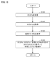
- FIG. 18 is a flowchart showing the processing procedure of this embodiment.
- FIG. 18 shows a processing procedure for displaying any of the graphs in FIGS. 8 to 13, 16, and 17.
- the processing procedure shown in FIG. 18 is realized by executing the program in the storage device 230 by the CPU 220 of the management device 10.
- the management device 10 acquires the external force Fz (step S100). Subsequently, the management device 10 acquires the external force Fxy (step S110). Furthermore, the management device 10 acquires the load torque Mz (step S120). More specifically, in steps S100 to S120, the management device 10 uses the detected values of the strain sensors N1 to N3, S4 as explained in FIGS. 3 and 4 to determine the external force Fz, the external force Fxy, and the load torque. Calculate Mz.
- the management device 10 displays a graph created based on at least two of the external force Fz, the external force Fxy, and the load torque Mz (step S130). That is, the management device displays any of the graphs in FIGS. 8 to 13, 16, and 17.
- FIG. 19 is a diagram showing the measurement results of a test for creating a normal region.
- FIG. 19 shows time series data of external force Fz, external force Fxy, and load torque Mz. More specifically, FIG. 19 shows the values of external force Fz, external force Fxy, and load torque Mz in the period from 0 to 17.5 seconds.
- FIG. 19 shows the measurement results of a test conducted under the following processing conditions.
- the rotation speed of the milling tool 50 is 2300 times/min.
- the feeding speed is 500 mm/min.
- the amount of cut in the radial direction is 10 mm. That is, each of the blade parts 6A to 6C cuts the workpiece so that the depth of cut gradually increases from 0 mm to 10 mm.
- each of the external force Fz, the external force Fxy, and the load torque Mz fluctuates over time.
- the period Dr1 is a period in which the depth of cut is 0 mm to 1 mm.
- the period Dr2 is a period in which the depth of cut is 4 mm to 5 mm.
- Period Dr3 is a period in which the depth of cut is 9 mm to 10 mm.
- FIG. 20 is a diagram displaying a graph based on the measurement results of FIG. 19.
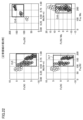
- FIG. 20 shows a graph in which the vertical axis is external force Fz and the horizontal axis is load torque Mz, a graph in which the vertical axis is external force Fxy and the horizontal axis is load torque Mz, and a graph in which the vertical axis is external force Fz and the horizontal axis is external force.
- Four graphs are shown: a graph in which Fxy is Fxy, and a graph in which the vertical axis is the ratio of external force Fz to load torque Mz and the horizontal axis is the ratio of external force Fxy to load torque Mz.
- plot P1 is a plot in period Dr1 in FIG. 19.
- Plot P2 is a plot in period Dr2 in FIG. 19.
- Plot P3 is a plot in period Dr3 in FIG. 19. That is, in FIG. 20, the values of external force Fz, external force Fxy, and load torque Mz shown in FIG. 19 are displayed as a graph for each period.
- the actual measured values of the external force Fz, external force Fxy, and load torque Mz shown in FIG. 19 are not displayed as plots, but the external force Fz, external force Fxy, and The moving average of the load torque Mz and the load torque Mz are displayed as a plot.
- each plot is arranged within a predetermined range on the graph within the same period.
- the test was conducted under machining conditions in which the depth of cut gradually increased, so the test was conducted under different machining conditions in period Dr1, period Dr2, and period Dr3. It can be said that this is being done.
- FIG. 21 is a diagram showing an example of setting a normal region in period Dr2.
- FIG. 21 displays graphs similar to the four graphs shown in FIG. 20.
- FIG. 21 shows normal regions Cr1, Cr2, Cr3, and Cr4 that overlap the four graphs, respectively.
- the normal regions Cr1 to Cr4 are determined based on the plot P2 in the period Dr2.
- the normal regions Cr1 to Cr4 are, for example, regions that include all the plots P2 in the period Dr2, and are regions that are represented by an ellipse or a circle centered on the average value of the set of plots P2.
- the normal regions Cr1 to Cr4 are determined by the management device 10. Note that the management device 10 may define the minimum area that includes all of the set of plots P2 as the normal areas Cr1 to Cr4 without using the average value of the set of plots P2.
- the state detection system 100 obtains the normal regions Cr1 to Cr4, which are the regions to be plotted, by performing the trial processing performed in FIGS. 19 and 20. Thereafter, when machining is performed under the machining conditions corresponding to period Dr2, if the newly detected plot is not located within the normal regions Cr1 to Cr4, it can be determined that an abnormality has occurred. That is, when a plot is detected in a region that is not within the normal regions Cr1 to Cr4, the management device 10 can display on the display device 40 that an abnormality has occurred. Further, the management device 10 may display the four graphs shown in FIG. 22 and the normal regions Cr1 to Cr4 on the display device 40 in real time. This allows the user to visually grasp in real time whether each plot is located within the normal ranges Cr1 to Cr4.
- FIG. 22 is a diagram illustrating an example of setting normal regions in periods Dr2 and Dr3.
- normal regions Cr5, Cr6, Cr7, and Cr8 are shown.
- the normal regions Cr5 to Cr8 are determined based on the plot P2 in the period Dr2 and the plot P3 in the period Dr3.
- the normal regions Cr5 to Cr8 are, for example, regions that include all the plots P2 and P3, and are rectangular regions centered on the average value of the set of plots P2 and P3.
- the state detection system 100 obtains the normal regions Cr5 to Cr8 through the trial processing performed in FIGS. 19 and 20. Thereafter, when machining is performed under the machining conditions corresponding to the periods Dr2 and Dr3, it can be determined whether an abnormality has occurred based on whether the newly detected plot is located within the normal regions Cr5 to Cr8. As shown in FIGS. 21 and 22, the state detection system 100 can create a normal region according to each processing condition.
- the state detection system 100 may use the actual measured value, The average value, maximum value, standard deviation, etc. may be used.
- the unit time can be determined based on the rotation speed of the milling tool 50.
- the state detection of the cutting tool using the external forces Fx, Fy, and Fxy has been described, but in a certain situation, the state detection system 100 may detect the condition of each axis instead of each of the external forces Fx, Fy, and Fxy. Torques Mx, My, and Mxy generated in the directions may also be used.
- the shaft portion 106 is held using the tool holder 30.
- the shaft portion 106 may be directly attached to the main shaft of the machine tool 70 without using a tool holder like the milling tool 50 of the present embodiment.
- the shaft portion 106 includes a housing.
- the strain sensors N1 to N3, S4 are stored inside a housing provided in the shaft portion 106.
- the strain sensors N1 to N3, S4 are arranged at equal intervals in the circumferential direction of the shaft portion 106, similarly to the milling tool 50 of this embodiment. In this way, even in the case of the milling tool 50 that is directly attached to the spindle without using a tool holder, by arranging the strain sensors N1 to N3, S4 in the housing of the shaft portion 106, the management device 10 can The external force and load torque generated at 50 can be obtained.
- the management device 10 has been described as being separate from the machine tool 70.
- the management device 10 may be included in the machine tool 70.
- the management device 10 and the machine tool 70 may be configured integrally.
- 6A to 6C blade section 10 management device, 20 motor, 30 tool holder, 40 display device, 50 milling tool, 60 workpiece, 70 machine tool, 100 condition detection system, Ag1 to Ag3 arrangement, Ar1 to Ar8 area, Cx compression Stress, D1 to D3 distance, Dv1 to Dv3 detected value, Ft, Fx, Fxy, FxyA to FxyC, Fy, Fz external force, K, Kt, Kx, Kxf, Ky, Kz, Kzf specific cutting force, Mz, MzA to MzC Load torque, N1 to N3, S4 strain sensor, N11 to N18, N21 to N28, N31 to N38, N41 to N48, P1 to P3 plot, Ns1 to Ns8 plot group, R1 radius, Rd rotation direction, St1 to St6 condition, Tx, Ty, Tz stress, ap, apD2, apD3 cutting depth, Cr1 to Cr8 normal range.
- condition detection system Ag1 to Ag
Landscapes
- Engineering & Computer Science (AREA)
- Physics & Mathematics (AREA)
- General Physics & Mathematics (AREA)
- Mechanical Engineering (AREA)
- Human Computer Interaction (AREA)
- Manufacturing & Machinery (AREA)
- Automation & Control Theory (AREA)
- Machine Tool Sensing Apparatuses (AREA)
Abstract
Description
本開示の目的は、転削加工に用いられる転削工具の状態を検出する状態検出システムを提供することである。
本開示によれば、転削工具に発生する回転軸に沿った方向に作用する外力、回転軸を法線とする平面に沿った方向に作用する外力、および回転を妨げる方向に作用する負荷トルクに基づいて、転削工具の異常判定に用いられる転削工具の状態を検出可能な状態検出システムを提供することができる。
最初に本開示の実施態様を列記して説明する。
以下、本開示の実施の形態について、図面を参照しながら詳細に説明する。なお、図中同一または相当部分には同一符号を付してその説明は繰り返さない。
図1は、本実施の形態における転削工具50の状態検出システム100の概略図である。図1における転削工具50の状態検出システム100は、マシニングセンタまたはフライス盤などの工作機械の転削工具に対して適用され得る。状態検出システム100は、管理装置10と、工作機械70とを備える。工作機械70は、モータ20と、転削工具50とを含む。
図2は、転削工具50の斜視図である。図2に示されているZ軸は、転削工具50の回転軸である。すなわち、転削工具50は、モータ20が駆動することによりZ軸を中心に回転する。転削工具50は、Z軸の正方向側からみたときに時計回りの回転方向Rdで回転する。互いに垂直なX軸およびY軸は、Z軸に対しても垂直な軸である。以降の説明において、各図におけるZ軸の正方向を上面側、負方向を下面側と称する場合がある。
以下では、図8~図10を用いて転削工具50の摩耗状態を検出する実験例を示す。図8~図10において、下記の加工条件にて行われた実験結果を示す。ワークの材質は、炭素鋼(S50C)である。転削工具50は、4枚刃のエンドミルである。工具径はφ6mmである。切削速度は、60m/minである。1つの刃部あたりの送り量は、0.015mm/t(tooth)である。軸方向の切り込み量は、1mmである。径方向の切り込み量は、2.4mmである。
以下では、図11~図13を用いて転削工具50の刃先欠損の状態を検出する実験例を示す。図11~図13において、下記の加工条件にて行われた実験結果を示す。ワークの材質は、ステンレス鋼(SUS304)である。転削工具50は、4枚刃のエンドミルである。工具径はφ16mmである。切削速度は、80m/minである。1つの刃部あたりの送り量は、0.10mm/t(tooth)である。軸方向の切り込み量は、2mmである。径方向の切り込み量は、10mmである。
図14は、外力と比切削抵抗と切削面積との関係を説明するための図である。上述したように、刃部はワーク60と繰り返して接触するため、切削面積の大きさにばらつきが発生し得る。工具摩耗または刃先欠損が生じることによって比切削抵抗Kが変化しても、切削面積の大きさにばらつきが発生すれば、外力Fx,Fy,Fz,および負荷トルクMzは、見かけ上、比切削抵抗Kが変化していないように相殺されてしまう可能性がある。そこで、以下では、切削面積の影響の排除する手法について説明する。
図15は、負荷トルクと切削面積との関係を説明するための図である。負荷トルクMzは、回転を妨げる力であり、転削工具50の接線方向に発生する外力Ftに対して転削工具50の半径R1を乗じた値である。上述したように、図6においては、刃部6Aにおける接線方向から延伸する矢印を負荷トルクMzAとして説明したが、実際には図15に示されるように外力FxyAの接線方向における分力である外力Ftに対して、転削工具50の半径R1を乗じた値である。
本実施の形態の状態検出システム100において、刃先の欠損のない状態においてプロットされる領域Ar1から異なる領域にプロットされたか否かをk近傍法を用いて判断する構成を説明した。しかしながら、異常が発生したか否かを判定する方法は、k近傍法を用いた方法に限られない。以下では、グラフ上に正常領域を作成する方法について説明する。
本実施の形態の転削工具50においては、工具ホルダ30を用いてシャフト部106が保持される構成であった。しかしながら、変形例の転削工具50では、本実施の形態の転削工具50のような工具ホルダを用いず、シャフト部106が工作機械70の主軸に直接取り付けられてもよい。この場合、シャフト部106は、ハウジングを備える。
Claims (7)
- 転削加工に用いられる転削工具の状態検出システムであって、
被切削物を切削するための刃部が設けられた第1端部と、工作機械に取り付けられる第2端部とを有するシャフト部を含み、前記シャフト部の回転軸を中心に回転可能な転削工具と、
前記シャフト部に取り付けられ、前記転削工具に作用する外力を検出する複数のセンサと、
表示装置と、
管理装置とを備え、
前記複数のセンサは、前記転削工具に対して、
前記回転軸に沿った第1方向に作用する第1力と、
前記回転軸を法線とする平面に沿った方向に作用する第2力と、
前記転削工具の回転を妨げる方向に作用する負荷トルクとを検出し、
前記管理装置は、前記第1力、前記第2力、および前記負荷トルクのうち少なくとも2つに基づく第1情報を前記表示装置に表示させる、状態検出システム。 - 前記管理装置は、グラフを用いて前記第1情報を表示する、請求項1に記載の状態検出システム。
- 前記管理装置は、前記第1情報に加えて、前記第1力、前記第2力、および前記負荷トルクのうち少なくとも2つに基づく第2情報を前記表示装置に表示させ、
前記第2情報は、前記第1情報と異なる情報である、請求項1または請求項2に記載の状態検出システム。 - 前記第1情報は、前記負荷トルクに対する前記第1力の割合と前記負荷トルクに対する前記第2力の割合に基づく情報である、請求項1に記載の状態検出システム。
- 前記複数のセンサは、
前記第1方向の歪みを検出し、前記シャフト部に取り付けられる第1歪センサ、第2歪センサ、および第3歪センサと、
前記シャフト部の周方向の歪みを検出し、前記シャフト部に取り付けられる第4歪センサとを含む、請求項1から請求項4のいずれか1項に記載の状態検出システム。 - 転削加工に用いられる転削工具の状態を検出する方法であって、
前記転削工具は、被切削物を切削するための刃部が設けられた第1端部と工作機械に取り付けられる第2端部とを有するシャフト部を含み、前記シャフト部の回転軸を中心に回転可能であり、
前記シャフト部には、前記転削工具に作用する外力を検出する複数のセンサが取り付けられ、
前記方法は、
前記複数のセンサの検出値を用いて、前記回転軸に沿った第1方向に作用する第1力を取得するステップと、
前記複数のセンサの検出値を用いて、前記回転軸を法線とする平面に沿った方向に作用する第2力を取得するステップと、
前記複数のセンサの検出値を用いて、前記転削工具の回転を妨げる方向に作用する負荷トルクを取得するステップと、
前記第1力、前記第2力、および前記負荷トルクのうち少なくとも2つに基づく第1情報を表示するステップとを含む、方法。 - 転削加工に用いられる転削工具の状態を検出するプログラムであって、
前記転削工具は、被切削物を切削するための刃部が設けられた第1端部と工作機械に取り付けられる第2端部とを有するシャフト部を含み、前記シャフト部の回転軸を中心に回転可能であり、
前記シャフト部には、前記転削工具に作用する外力を検出する複数のセンサが取り付けられ、
コンピュータに、
前記複数のセンサの検出値を用いて、前記回転軸に沿った第1方向に作用する第1力を取得するステップと、
前記回転軸を法線とする平面に沿った方向に作用する第2力を取得するステップと、
前記転削工具の回転を妨げる方向に作用する負荷トルクを取得するステップと、
前記第1力、前記第2力、および前記負荷トルクのうち少なくとも2つに基づく第1情報を表示するステップとを実行させる、プログラム。
Priority Applications (5)
| Application Number | Priority Date | Filing Date | Title |
|---|---|---|---|
| JP2022575362A JP7243945B1 (ja) | 2022-09-06 | 2022-09-06 | 状態検出システム、方法、およびプログラム |
| US19/103,834 US20260084227A1 (en) | 2022-09-06 | 2022-09-06 | State detection system, method, and program |
| CN202280099574.1A CN119768250A (zh) | 2022-09-06 | 2022-09-06 | 状态检测系统、方法以及程序 |
| PCT/JP2022/033385 WO2024052978A1 (ja) | 2022-09-06 | 2022-09-06 | 状態検出システム、方法、およびプログラム |
| EP22958057.6A EP4585365A4 (en) | 2022-09-06 | 2022-09-06 | STATE DETECTION SYSTEM, METHOD AND PROGRAM |
Applications Claiming Priority (1)
| Application Number | Priority Date | Filing Date | Title |
|---|---|---|---|
| PCT/JP2022/033385 WO2024052978A1 (ja) | 2022-09-06 | 2022-09-06 | 状態検出システム、方法、およびプログラム |
Publications (1)
| Publication Number | Publication Date |
|---|---|
| WO2024052978A1 true WO2024052978A1 (ja) | 2024-03-14 |
Family
ID=85685007
Family Applications (1)
| Application Number | Title | Priority Date | Filing Date |
|---|---|---|---|
| PCT/JP2022/033385 Ceased WO2024052978A1 (ja) | 2022-09-06 | 2022-09-06 | 状態検出システム、方法、およびプログラム |
Country Status (5)
| Country | Link |
|---|---|
| US (1) | US20260084227A1 (ja) |
| EP (1) | EP4585365A4 (ja) |
| JP (1) | JP7243945B1 (ja) |
| CN (1) | CN119768250A (ja) |
| WO (1) | WO2024052978A1 (ja) |
Families Citing this family (2)
| Publication number | Priority date | Publication date | Assignee | Title |
|---|---|---|---|---|
| JPWO2024241580A1 (ja) * | 2023-05-25 | 2024-11-28 | ||
| JP2025040666A (ja) * | 2023-09-12 | 2025-03-25 | Dmg森精機株式会社 | 工作機械、工作機械の制御方法および工作機械の制御プログラム |
Citations (8)
| Publication number | Priority date | Publication date | Assignee | Title |
|---|---|---|---|---|
| JPS58217247A (ja) | 1982-06-04 | 1983-12-17 | Okuma Mach Works Ltd | 硬質フオームの曲面加工方法 |
| JPS59142048A (ja) | 1983-01-26 | 1984-08-15 | Mitsubishi Electric Corp | 工具異常検出装置 |
| JPH096432A (ja) * | 1995-06-14 | 1997-01-10 | Mitsubishi Electric Corp | 制御システムの異常検知装置 |
| JPH0976144A (ja) | 1995-09-14 | 1997-03-25 | Fanuc Ltd | 工作機械における加工状態監視方法 |
| JP2020203356A (ja) * | 2019-06-18 | 2020-12-24 | 株式会社ジェイテクト | 加工工具の異常検知装置 |
| JP2021137962A (ja) * | 2019-08-09 | 2021-09-16 | 住友電気工業株式会社 | 転削工具、モジュール、切削システム、処理方法および処理プログラム |
| JP6973689B1 (ja) * | 2020-04-13 | 2021-12-01 | 住友電気工業株式会社 | 切削システム、表示システム、処理装置、処理方法および処理プログラム |
| JP7047979B1 (ja) * | 2020-08-07 | 2022-04-05 | 住友電気工業株式会社 | 切削システム、表示システム、処理装置、処理方法および処理プログラム |
Family Cites Families (2)
| Publication number | Priority date | Publication date | Assignee | Title |
|---|---|---|---|---|
| US4802095A (en) * | 1986-12-24 | 1989-01-31 | The Boeing Company | Method for indicating end mill wear |
| US20140216170A1 (en) * | 2013-02-05 | 2014-08-07 | Georgia Tech Research Corporation | Systems And Methods For Monitoring Cutting Forces In Peripheral End Milling |
-
2022
- 2022-09-06 JP JP2022575362A patent/JP7243945B1/ja active Active
- 2022-09-06 WO PCT/JP2022/033385 patent/WO2024052978A1/ja not_active Ceased
- 2022-09-06 US US19/103,834 patent/US20260084227A1/en active Pending
- 2022-09-06 CN CN202280099574.1A patent/CN119768250A/zh active Pending
- 2022-09-06 EP EP22958057.6A patent/EP4585365A4/en active Pending
Patent Citations (8)
| Publication number | Priority date | Publication date | Assignee | Title |
|---|---|---|---|---|
| JPS58217247A (ja) | 1982-06-04 | 1983-12-17 | Okuma Mach Works Ltd | 硬質フオームの曲面加工方法 |
| JPS59142048A (ja) | 1983-01-26 | 1984-08-15 | Mitsubishi Electric Corp | 工具異常検出装置 |
| JPH096432A (ja) * | 1995-06-14 | 1997-01-10 | Mitsubishi Electric Corp | 制御システムの異常検知装置 |
| JPH0976144A (ja) | 1995-09-14 | 1997-03-25 | Fanuc Ltd | 工作機械における加工状態監視方法 |
| JP2020203356A (ja) * | 2019-06-18 | 2020-12-24 | 株式会社ジェイテクト | 加工工具の異常検知装置 |
| JP2021137962A (ja) * | 2019-08-09 | 2021-09-16 | 住友電気工業株式会社 | 転削工具、モジュール、切削システム、処理方法および処理プログラム |
| JP6973689B1 (ja) * | 2020-04-13 | 2021-12-01 | 住友電気工業株式会社 | 切削システム、表示システム、処理装置、処理方法および処理プログラム |
| JP7047979B1 (ja) * | 2020-08-07 | 2022-04-05 | 住友電気工業株式会社 | 切削システム、表示システム、処理装置、処理方法および処理プログラム |
Non-Patent Citations (1)
| Title |
|---|
| See also references of EP4585365A4 |
Also Published As
| Publication number | Publication date |
|---|---|
| JPWO2024052978A1 (ja) | 2024-03-14 |
| EP4585365A4 (en) | 2025-10-29 |
| EP4585365A1 (en) | 2025-07-16 |
| CN119768250A (zh) | 2025-04-04 |
| US20260084227A1 (en) | 2026-03-26 |
| JP7243945B1 (ja) | 2023-03-22 |
Similar Documents
| Publication | Publication Date | Title |
|---|---|---|
| JP7243945B1 (ja) | 状態検出システム、方法、およびプログラム | |
| JP5411055B2 (ja) | 工具寿命検出方法、および工具寿命検出装置 | |
| Colpani et al. | Tool wear analysis in micromilling of titanium alloy | |
| WO2013150905A1 (ja) | 切削加工システム及び方法 | |
| US9588512B2 (en) | Setting method of revolutions per minute on real time of spinning cutting tool, and control device | |
| Ozturk et al. | Investigation of spindle bearing preload on dynamics and stability limit in milling | |
| TW201923495A (zh) | 刀具磨耗檢測裝置、其檢測方法及刀具磨耗補償方法 | |
| JP6722052B2 (ja) | 多刃工具の異常検知方法 | |
| JP2012254499A (ja) | 工作機械の加工異常検知装置及び加工異常検知方法 | |
| KR20190013344A (ko) | 가공좌표계상 가공시간에 따라 가공위치와 물리적 가공절삭 특성값을 매핑하는 절삭특성맵을 활용하여 절삭상태를 지능적으로 감시 및 진단하고, 절삭조건을 제어할 수 있는 지능형 cnc공작기계 제어시스템 | |
| Rizal et al. | Design and construction of a strain gauge-based dynamometer for a 3-axis cutting force measurement in turning process | |
| JP7614473B2 (ja) | 工作機械の外部処理システム | |
| JP7313001B2 (ja) | 工具寿命検出装置及び工具寿命検出方法 | |
| JP5089618B2 (ja) | 工具寿命検出方法及び工具寿命検出装置 | |
| JP6950856B2 (ja) | 切削工具、切削システム、処理方法および処理プログラム | |
| Gao et al. | Meso-scale tool breakage prediction based on finite element stress analysis for shoulder milling of hardened steel | |
| Kasim et al. | Cutting tool wear progression index via signal element variance | |
| JP7619288B2 (ja) | 切削工具およびモジュール | |
| JP7260077B1 (ja) | 切削システムおよび転削工具の状態判定方法 | |
| JP6885529B1 (ja) | 切削工具、切削システム、処理方法および処理プログラム | |
| JP5666397B2 (ja) | 工作機械 | |
| JP7563253B2 (ja) | 測定システム、取得装置、取得方法、変換情報取得方法、製造方法及びコンピュータプログラム | |
| JP6277073B2 (ja) | 工作物のバランス測定方法、バランス修正加工方法及びそれを用いた工作機械 | |
| Jayaswal et al. | An investigation of tool condition monitoring | |
| Ahmed | An online approach for power consumption monitoring of tool condition |
Legal Events
| Date | Code | Title | Description |
|---|---|---|---|
| ENP | Entry into the national phase |
Ref document number: 2022575362 Country of ref document: JP Kind code of ref document: A |
|
| 121 | Ep: the epo has been informed by wipo that ep was designated in this application |
Ref document number: 22958057 Country of ref document: EP Kind code of ref document: A1 |
|
| WWE | Wipo information: entry into national phase |
Ref document number: 202280099574.1 Country of ref document: CN |
|
| WWP | Wipo information: published in national office |
Ref document number: 202280099574.1 Country of ref document: CN |
|
| WWE | Wipo information: entry into national phase |
Ref document number: 2022958057 Country of ref document: EP |
|
| NENP | Non-entry into the national phase |
Ref country code: DE |
|
| ENP | Entry into the national phase |
Ref document number: 2022958057 Country of ref document: EP Effective date: 20250407 |
|
| WWP | Wipo information: published in national office |
Ref document number: 2022958057 Country of ref document: EP |