WO2024062575A1 - Procédé de fabrication d'article moulé à la presse et dispositif de moulage à la presse - Google Patents
Procédé de fabrication d'article moulé à la presse et dispositif de moulage à la presse Download PDFInfo
- Publication number
- WO2024062575A1 WO2024062575A1 PCT/JP2022/035261 JP2022035261W WO2024062575A1 WO 2024062575 A1 WO2024062575 A1 WO 2024062575A1 JP 2022035261 W JP2022035261 W JP 2022035261W WO 2024062575 A1 WO2024062575 A1 WO 2024062575A1
- Authority
- WO
- WIPO (PCT)
- Prior art keywords
- edge
- die
- press
- blank
- punch
- Prior art date
- Legal status (The legal status is an assumption and is not a legal conclusion. Google has not performed a legal analysis and makes no representation as to the accuracy of the status listed.)
- Ceased
Links
Images


Classifications
-
- B—PERFORMING OPERATIONS; TRANSPORTING
- B21—MECHANICAL METAL-WORKING WITHOUT ESSENTIALLY REMOVING MATERIAL; PUNCHING METAL
- B21D—WORKING OR PROCESSING OF SHEET METAL OR METAL TUBES, RODS OR PROFILES WITHOUT ESSENTIALLY REMOVING MATERIAL; PUNCHING METAL
- B21D19/00—Flanging or other edge treatment, e.g. of tubes
- B21D19/08—Flanging or other edge treatment, e.g. of tubes by single or successive action of pressing tools, e.g. vice jaws
-
- B—PERFORMING OPERATIONS; TRANSPORTING
- B21—MECHANICAL METAL-WORKING WITHOUT ESSENTIALLY REMOVING MATERIAL; PUNCHING METAL
- B21D—WORKING OR PROCESSING OF SHEET METAL OR METAL TUBES, RODS OR PROFILES WITHOUT ESSENTIALLY REMOVING MATERIAL; PUNCHING METAL
- B21D22/00—Shaping without cutting, by stamping, spinning, or deep-drawing
- B21D22/20—Deep-drawing
- B21D22/22—Deep-drawing with devices for holding the edge of the blanks
-
- B—PERFORMING OPERATIONS; TRANSPORTING
- B21—MECHANICAL METAL-WORKING WITHOUT ESSENTIALLY REMOVING MATERIAL; PUNCHING METAL
- B21D—WORKING OR PROCESSING OF SHEET METAL OR METAL TUBES, RODS OR PROFILES WITHOUT ESSENTIALLY REMOVING MATERIAL; PUNCHING METAL
- B21D19/00—Flanging or other edge treatment, e.g. of tubes
- B21D19/08—Flanging or other edge treatment, e.g. of tubes by single or successive action of pressing tools, e.g. vice jaws
- B21D19/088—Flanging or other edge treatment, e.g. of tubes by single or successive action of pressing tools, e.g. vice jaws for flanging holes
-
- B—PERFORMING OPERATIONS; TRANSPORTING
- B21—MECHANICAL METAL-WORKING WITHOUT ESSENTIALLY REMOVING MATERIAL; PUNCHING METAL
- B21D—WORKING OR PROCESSING OF SHEET METAL OR METAL TUBES, RODS OR PROFILES WITHOUT ESSENTIALLY REMOVING MATERIAL; PUNCHING METAL
- B21D53/00—Making other particular articles
- B21D53/88—Making other particular articles other parts for vehicles, e.g. cowlings, mudguards
Definitions
- the present disclosure relates to a method for manufacturing a press-molded product and a press-molding device.
- press-formed products are used as structural members for automobiles.
- a press-molded product is manufactured by press-molding a blank using a punch and a die. The blank is pushed into the die side by a punch and formed into the desired shape.
- Patent Document 1 discloses a method for manufacturing a press-molded product using a pad in addition to a punch and a die.
- the side surface of the punch and the side surface of the die that cooperates with the punch include curved surfaces.
- a blank provided with a step shape in advance is held between a punch and a pad, and a die is moved along the side surface of the punch relative to the punch. In this way, a press-molded product is formed from the blank.
- Patent Document 2 also discloses a method for manufacturing a press-molded product using a punch, a die, and a pad.
- the edge of the upper surface of the punch has a concave shape in the center when viewed from above.
- the die has a shape that corresponds to the punch.
- a blank placed on the upper surface of a punch is pressed down with a pad to form a bead on the blank. Thereafter, the blank is bent using a punch and die to form a press-formed product.
- Patent No. 6052478 Japanese Patent No. 6202059
- the edge of the die on the punch side includes a curved portion.
- the curved portion is a portion that curves convexly toward the punch side when the die is viewed from above.
- the portion of the blank that is drawn toward the curved portion is stretched in the extending direction of the curved portion.
- cracks may occur in the blank.
- An object of the present disclosure is to suppress the occurrence of cracks in blanks in the production of press-formed products.
- a method for manufacturing a press-formed product according to the present disclosure includes sandwiching a blank between a die and a blank holder, and pushing the blank in the pressing direction with a punch.
- the punch side edge of the die When viewed from the press direction, the punch side edge of the die includes a curved portion that is convexly curved toward the punch side and extends with a radius of curvature of less than 400 mm.
- the distance between the edge of the blank holder on the punch side and the edge of the die on the punch side on a line perpendicular to the extending direction of the edges of the die changes along the edge of the die. When viewed from the press direction, this spacing is smallest at the curved portion.
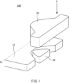
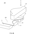
- FIG. 1 is a schematic perspective view of a press molding apparatus according to a first embodiment.
- FIG. 2 is a cross-sectional view of the press molding apparatus shown in FIG. 1.
- FIG. 3 is a diagram schematically showing the relationship between a punch, a die, and a blank holder included in the press forming apparatus shown in FIG. 1 when viewed from the press direction.
- FIG. 4A is a schematic diagram for explaining the method for manufacturing a press-formed product according to the first embodiment.
- FIG. 4B is a schematic diagram for explaining the method for manufacturing a press-formed product according to the first embodiment.
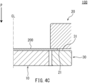
- FIG. 4C is a schematic diagram for explaining the method for manufacturing a press-formed product according to the first embodiment.
- FIG. 4A is a schematic diagram for explaining the method for manufacturing a press-formed product according to the first embodiment.
- FIG. 4B is a schematic diagram for explaining the method for manufacturing a press-formed product according to the first embodiment.
- FIG. 4C is a schematic diagram for explaining the method
- FIG. 4D is a schematic diagram for explaining the method for manufacturing a press-formed product according to the first embodiment.
- FIG. 4E is a schematic diagram for explaining the method for manufacturing a press-formed product according to the first embodiment.
- FIG. 4F is a schematic diagram for explaining the method for manufacturing a press-formed product according to the first embodiment.
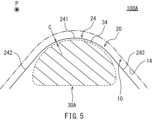
- FIG. 5 is a diagram schematically showing the relationship between a punch, a die, and a blank holder included in the press forming apparatus according to the second embodiment when viewed from the press direction.
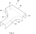
- FIG. 6 is a schematic perspective view of a press-formed product manufactured by the press-forming apparatus according to the third embodiment.
- FIG. 7 is a diagram schematically showing the relationship between a punch, a die, and a blank holder included in the press forming apparatus according to the third embodiment when viewed from the press direction.
- FIG. 8 is a diagram schematically showing the relationship among the punch, die, and blank holder when viewed from the press direction in a modification of the above embodiment.
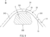
- FIG. 9 is a diagram showing a schematic diagram of the relationship between the punch, the die, and the blank holder when viewed from the pressing direction in another modified example of the above embodiment.
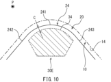
- FIG. 10 is a diagram schematically showing the relationship among the punch, die, and blank holder when viewed from the press direction in yet another modification of the above embodiment.
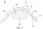
- FIG. 11 is a diagram schematically showing the relationship among the punch, die, and blank holder when viewed from the press direction in yet another modification of the above embodiment.
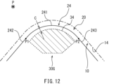
- FIG. 12 is a diagram showing a schematic diagram of the relationship between the punch, the die, and the blank holder when viewed from the pressing direction in yet another modified example of the above embodiment.
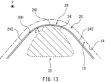
- FIG. 13 is a diagram schematically showing the relationship among a punch, a die, and a blank holder when viewed from the press direction in yet another modification of the above embodiment.
- FIG. 14 is a diagram schematically showing the relationship among a punch, a die, and a blank holder when viewed from the press direction in yet another modification of the above embodiment.
- FIG. 15 is a schematic perspective view of a press molding apparatus according to a modification of the above embodiment.
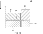
- FIG. 16 is a cross-sectional view of the press molding apparatus shown in FIG. 15.
- FIG. 17 is a diagram of a punch and die used in normal press forming projected onto a plane perpendicular to the pressing direction.
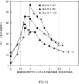
- FIG. 18 is a diagram showing the analysis results when the blank is pulled out from between the die and the blank holder and the forming is completed.
- FIG. 19 is a diagram showing an analysis result when forming is completed with the blank sandwiched between the die and the blank holder.
- FIG. 17 is a diagram of a punch 91 and die 92 used in normal press forming projected onto a plane perpendicular to the pressing direction.
- the blank is drawn toward the edge 921 of the die 92 on the punch 91 side.
- the edge 921 of the die 92 includes a curved portion 921a and straight portions 921b provided on both sides of the curved portion 921a when viewed from the press direction, the portion of the blank that is drawn toward the curved portion 921a is as shown in FIG.
- the curved portion 921a is stretched in the extending direction.
- the broken lines in FIG. 17 are examples of iso-thickness lines of the blank during press molding.
- the isothickness line is a line that connects points of equal thickness in the blank during press forming. In FIG. 17, the thicker the isothickness line, the thicker the blank is at that position.
- One method for suppressing blank cracking is to apply compressive stress in the thickness direction of the blank.
- a method of applying compressive stress to a blank in the thickness direction to suppress cracking of the blank is referred to as a developed method.
- the present inventors came up with the idea of applying the developed method to a case where the punch-side edge of the die includes a curved portion, and completed a method for manufacturing a press-formed product according to an embodiment.
- the method for manufacturing a press-formed product includes sandwiching a blank between a die and a blank holder, and pushing the blank in the pressing direction with a punch.
- the punch side edge of the die includes a curved portion that is convexly curved toward the punch side and extends with a radius of curvature of less than 400 mm.
- the distance between the edge of the blank holder on the punch side and the edge of the die on the punch side on a line perpendicular to the extending direction of the edges of the die changes along the edge of the die.
- this spacing is smallest at the curved portion (first configuration).
- the punch side edge of the die includes a curved portion when viewed from the press direction
- the thickness of the blank becomes thinner.
- the distance between the edge of the blank holder on the punch side and the edge of the die on the punch side is minimum at the curved portion. Therefore, the part of the blank that is drawn toward the curved part, that is, the reduced thickness part, is held between a die and a blank holder up to the vicinity of the curved part, and the reduced thickness part is compressed in the thickness direction to the vicinity of the curved part. Stress can be applied. Therefore, in the production of press-molded products, it is possible to suppress the occurrence of cracks in the blank.
- the distance between the punch-side edge of the blank holder and the punch-side edge of the die changes along the extending direction of the die edge. More specifically, at the edge of the die, there is a location in the curved portion where the distance from the edge of the blank holder is the smallest, and the distance from the edge of the blank holder is large at other locations. Therefore, during press forming, the blank is pressed by the die and blank holder to the vicinity of the edge of the die at the point where the distance between the edge of the blank holder and the edge of the die is the minimum, while the blank is pressed by the die and blank holder at the point adjacent to that point. The blank is not pressed close to the edge. Thereby, material can be allowed to flow into the reduced thickness portion of the blank during press forming, and the reduction in the thickness of the blank can be alleviated. Therefore, the occurrence of cracks in the blank can be further suppressed.
- the distance between the edge of the blank holder on the punch side and the edge of the die on the punch side may increase as the distance from the curved portion increases (second composition).
- the distance between the edge of the blank holder and the edge of the die increases as it moves away from the curved portion.
- the developed construction method can be applied to the entire portion of the blank that is drawn toward the curved portion, and the material can be encouraged to flow into the portion. That is, since the distance between the edge of the blank holder and the curved part of the edge of the die is smaller than the distance between the edge of the blank holder and other parts of the edge of the die, the blank is drawn toward the curved part.
- Compressive stress can be applied to the entire portion in the thickness direction up to the vicinity of the curved portion using a die and a blank holder.
- the edge of the die on the punch side may consist only of a curved portion when viewed from the pressing direction.
- the distance between the edge of the blank holder on the punch side and the edge of the die on the punch side may be largest at the end of the curved portion (third configuration).
- the line length of the part of the punch side edge of the blank holder that has the smallest distance from the punch side edge of the die is the line length of the curved part. It may be 0.5 times or more and 2.5 times or less (fourth configuration).
- the press molding device includes a punch, a die, and a blank holder.
- the punch side edge of the die When viewed from the press direction, the punch side edge of the die includes a curved portion that is convexly curved toward the punch side and extends with a radius of curvature of less than 400 mm.
- the distance between the edge of the blank holder on the punch side and the edge of the die on the punch side on a line perpendicular to the extending direction of the edge of the die changes along the edge of the die. When viewed from the press direction, this spacing is smallest at the curved portion (fifth configuration).
- the distance between the edge of the blank holder on the punch side and the edge of the die on the punch side may increase as the distance from the curved portion increases (sixth configuration).
- the edge of the die on the punch side when viewed from the press direction, may consist only of a curved portion.
- the distance between the punch-side edge of the blank holder and the punch-side edge of the die when viewed from the press direction, may be largest at the end of the curved portion (seventh configuration).
- the line length of the part of the punch side edge of the blank holder that has the smallest distance from the punch side edge of the die is 0.5 of the line length of the curved part. It may be greater than or equal to 2.5 times (eighth configuration).
- FIG. 1 is a schematic perspective view of a press molding apparatus 100 according to the first embodiment.
- the press molding apparatus 100 includes a punch 10, a die 20, and a blank holder 30.
- FIG. 1 shows only the die 20 on one side with respect to the virtual line CL, the die 20 may be arranged on both sides of the punch 10. These dies 20 may be separate bodies or may be formed integrally. In this embodiment, the space between these dies 20 may be referred to as a die hole.
- a blank holder 30 is provided corresponding to each of the dies 20.
- the punch 10 and blank holder 30 are configured to be movable relative to the die 20 in the press direction P.
- the punch 10 and the blank holder 30 may be moved in the press direction P, and the die 20 may be moved in the press direction P, for example, by a drive mechanism (not shown) such as a fluid pressure cylinder. .
- the blank holder 30 is movable relative to the punch 10 in the press direction P by, for example, a drive mechanism (not shown) such as a cushion.
- the pressing direction P is, for example, a vertical direction. If the press direction P is vertical, a blank 200 (FIG. 4A), which will be described later, can be easily placed between the punch 10 and the die 20.
- FIG. 2 is a cross-sectional view of the press molding apparatus 100 shown in FIG. 1.
- the cross section of the press forming apparatus 100 is a cross section when the press forming apparatus 100 is cut along a plane parallel to the press direction P and perpendicular to the longitudinal direction of the punch 10.
- the direction perpendicular to the press direction P on the cross section of the press molding apparatus 100 is referred to as the width direction of the press molding apparatus 100.
- FIG. 2 like FIG. 1, only a portion of the press molding apparatus 100 on one side with respect to the virtual line CL is shown.
- the virtual line CL is, for example, the center line of the press molding apparatus 100 in the width direction.
- the punch 10 includes a punch top surface 11, a punch shoulder 12, and a punch side surface 13.
- the punch top surface 11 is a surface that intersects with the press direction P.
- the punch top surface 11 may be perpendicular to the pressing direction P.
- the punch top surface 11 substantially extends in the width direction in a cross-sectional view of the press forming apparatus 100.
- the punch shoulder 12 is continuous with the end of the punch top surface 11.
- the punch shoulder 12 has, for example, a substantially arcuate shape in a cross-sectional view of the press forming apparatus 100. This is because if the punch shoulder 12 is sharp, the blank 200 (FIG. 4A) may be cut by the punch shoulder 12 during press forming.
- the radius of curvature of the punch shoulder 12 may be 1.0 mm or more.
- the punch side surface 13 is connected to the punch top surface 11 via the punch shoulder 12.
- the punch side surface 13 extends from the punch shoulder 12 in the pressing direction P when the press forming apparatus 100 is viewed in cross section. In a cross-sectional view of the press forming apparatus 100, the punch side surface 13 may be parallel to the press direction P or may be inclined with respect to the press direction P.
- the die 20 includes a pressing surface 21, a die shoulder 22, and a die side surface 23.
- the pressing surface 21 of the die 20 is, for example, a flat surface substantially perpendicular to the pressing direction P.
- the die shoulder 22 is continuous with the end of the pressing surface 21 on the punch 10 side in a cross-sectional view of the press forming apparatus 100.
- the die shoulder 22 has, for example, a substantially arcuate shape in a cross-sectional view of the press molding apparatus 100. This is because if the die shoulder 22 is sharp, the blank 200 (FIG. 4A) may be cut by the die shoulder 22 during press molding.
- the radius of curvature of the die shoulder 22 may be 1.0 mm or more.
- the die side surface 23 is connected to the pressing surface 21 via the die shoulder 22.
- the die side surface 23 extends in the press direction P from the die shoulder 22 in a cross-sectional view of the press molding apparatus 100.
- the die side surface 23 has a shape corresponding to the punch side surface 13.
- the blank holder 30 is arranged outside the punch 10 in the width direction of the press forming apparatus 100. Moreover, the blank holder 30 is arranged so as to face the die 20 in the press direction P.
- the blank holder 30 includes a pressing surface 31, a holder shoulder 32, and a holder side surface 33.
- the pressing surface 31 of the blank holder 30 faces the pressing surface 21 of the die 20 in the pressing direction P.
- the pressing surface 31 is, for example, a flat surface substantially perpendicular to the pressing direction P.
- the holder shoulder 32 is continuous with the end of the pressing surface 31 on the punch 10 side in a cross-sectional view of the press forming apparatus 100.
- the holder side surface 33 is connected to the pressing surface 31 via the holder shoulder 32.
- the holder side surface 33 extends in the press direction P from the holder shoulder 32 in a cross-sectional view of the press molding apparatus 100.
- the holder side surface 33 faces the punch side surface 13 in the width direction of the press molding apparatus 100.
- the press forming apparatus 100 may have a shape that is symmetrical with respect to the width center line CL in a cross-sectional view, but may also have a shape that is asymmetric with respect to the width center line CL.
- FIG. 3 is a diagram schematically showing the relationship among the punch 10, die 20, and blank holder 30 when viewed from the press direction P.
- FIG. 3 is a schematic diagram showing the punch 10, the die 20, and the blank holder 30 when projected onto a plane perpendicular to the press direction P.
- the edge 24 of the die 20 is shown in solid lines
- the edge 34 of the blank holder 30 is shown in broken lines.
- the blank holder 30 is provided with hatching.
- the edge 14 of the punch 10 is shown by a dashed line.
- the edge 14 of the punch 10 in FIG. 3 is the punch side surface 13 coplanar with the pressing surface 21 of the die 20.
- the edge 14 of the punch 10 on the die 20 side extends along the edge 24 of the die 20 on the punch 10 side.
- the edge 24 of the die is the die shoulder 22.
- Edge 14 of punch 10 has a shape that corresponds to edge 24 of die 20.
- the edge 14 of the punch 10 is substantially parallel to the edge 24 of the die 20 throughout.
- the clearance between the edge 14 of the punch 10 and the edge 24 of the die 20 when viewed from the press direction P is such that the material for press forming is
- the thickness of the blank is greater than or equal to the thickness of the blank.
- the edge 24 of the die 20 includes a curved portion 241 and straight portions 242 and 243.
- the curved portion 241 is curved convexly toward the punch 10 side when viewed from the press direction P.
- the curved portion 241 extends with a radius of curvature of less than 400 mm when viewed from the press direction P.
- the curved portion 241 may have a constant radius of curvature, or may have a radius of curvature that changes.
- the radius of curvature of an arc passing through three points, that is, the point and the points located on both sides thereof is calculated.
- the section where the radius of curvature is less than 400 mm is regarded as a curved section 241, and the section where the radius of curvature is 400 mm or more is regarded as a non-curved section (straight section).
- the straight parts 242 and 243 are continuously provided at both ends of the curved part 241. When viewed from the press direction P, the straight parts 242 and 243 extend from the curved part 241 so as to separate from each other as they move away from the curved part 241. When viewed from the press direction P, the straight portions 242 and 243 may be located on tangents to both ends of the curved portion 241.
- the blank holder 30 is provided so as to correspond to only a part of the edge 24 of the die 20.
- the blank holder 30 is arranged at a position corresponding to the curved portion 241 of the edge 24 of the die 20 when viewed from the press direction P.
- the blank holder 30 has a shape that becomes substantially tapered toward the punch 10 when viewed from the press direction P.
- the blank holder 30 has a generally triangular shape when viewed from the press direction P.
- the distance C between the edge 34 of the blank holder 30 on the punch 10 side and the edge 24 of the die 20 changes along the edge 24 of the die 20. That is, the distance C between the edge 34 of the blank holder 30 and the edge 24 of the die 20 is not constant over the entire length of the edge 34 of the blank holder 30.
- the distance C is the distance between the edge 34 of the blank holder 30 and the edge 24 of the die 20 on a perpendicular line to the extending direction of the edge 24 of the die 20 when viewed from the press direction P.
- the interval C is the distance from the edge 34 of the blank holder 30 to the edge 24 of the die 20 in the normal direction of the curved part 241 or the perpendicular direction of the straight parts 242, 243 when viewed from the press direction P.
- the perpendicular to the extending direction of the edge 24 of the die 20 is a perpendicular or normal line to the edge of the die shoulder 22 (FIG. 2) on the punch 10 side when viewed from the press direction P.
- a perpendicular to the extending direction of the edge 24 of the die 20 generally coincides with the direction in which the blank is drawn toward the die hole when forming the blank using the press forming apparatus 100 (FIGS. 1 and 2).
- the edge 34 of the blank holder 30 is the edge of the holder shoulder 32 (FIG. 2) on the punch 10 side when viewed from the press direction P.
- the distance C between the edge 34 of the blank holder 30 and the edge 24 of the die 20 is smallest at the curved portion 241. That is, if a perpendicular line to the edge 24 of the die 20 is drawn at a position where the distance between the edge 24 of the die 20 and the edge 34 of the blank holder 30 is minimum when viewed from the press direction P, the perpendicular line will be drawn at the curved portion 241. It will pass through.
- the minimum value of the distance C is, for example, smaller than the clearance between the edge 14 of the punch 10 and the edge 24 of the die 20.
- the minimum value of the interval C may be 0 mm.
- the edge 34 of the blank holder 30 and the edge 24 of the die 20 are closest to each other at the point where the edge 34 of the blank holder 30 and the edge 24 of the die 20 are closest to each other. 24 overlap, and at other locations, the edge 24 of the die 20 is arranged on the punch 10 side with respect to the edge 34 of the blank holder 30.
- the minimum value of the distance C is larger than 0 mm, the entire edge 34 of the blank holder 30 is arranged on the opposite side of the punch 10 with respect to the edge 24 of the die 20 when viewed from the press direction P.
- the line length of the portion of the edge 34 of the blank holder 30 with the smallest distance C from the edge 24 of the die 20 is, for example, 0.5 or more times the line length of the curved portion 241. It can be 5 times or less.
- the line length of the curved portion 241, that is, the length in the extending direction of the curved portion 241, can be the product of the included angle ⁇ (rad) and the radius of curvature of the curved portion 241.
- the included angle ⁇ is an angle formed by tangents at both ends of the curved portion 241 when viewed from the press direction P.
- the included angle ⁇ may be greater than or equal to 1/3 ⁇ (rad) and less than or equal to 2/3 ⁇ (rad).
- the radius of curvature of the curved portion 241 can be, for example, the average value of the radii of curvature measured at 5.0 mm intervals as described above.
- the distance C between the edge 34 of the blank holder 30 and the edge 24 of the die 20 is minimum at the top of the curved portion 241 convex toward the punch 10. .
- the distance C between the edge 34 of the blank holder 30 and the edge 24 of the die 20 increases as the distance from the top of the curved portion 241 increases. That is, the interval C changes within the range of the curved portion 241.
- the distance C between the edge 34 of the blank holder 30 and the edge 24 of the die 20 becomes even larger at the straight portions 242 and 243 on both sides of the curved portion 241.
- the distance C increases as the distance from the curved portion 241 increases.
- a blank 200 is first prepared in manufacturing a press-molded product.
- the blank 200 can be obtained, for example, by blanking a rolled steel plate.
- the blank 200 is formed, for example, in the shape of an expanded target press-formed product.
- the developed shape of the target press-formed product can be obtained, for example, by using a function of finite element analysis software for analyzing press-forming that derives the blank shape before molding from the shape of the molded product.
- Blank 200 may be a steel plate.
- Blank 200 is preferably a high strength steel plate.
- the tensile strength of the blank 200 is, for example, 440 MPa or more.
- the tensile strength of the blank 200 may be 590 MPa or more, or 780 MPa or more.
- the tensile strength of the blank 200 may be 980 MPa or more, 1180 MPa or more, or 1300 MPa or more.
- the thickness of the blank 200 may be, for example, 0.4 mm or more and 6.0 mm or less, or 1.0 mm or more and 4.0 mm or less.
- the method for manufacturing a press-formed product includes sandwiching the blank 200 between a die 20 and a blank holder 30, and pushing the blank 200 in the press direction P with the punch 10.
- the blank 200 is placed between the punch 10 and blank holder 30, and the die 20.
- the blank 200 is placed on the punch top surface 11 and the pressing surface 31 of the blank holder 30.
- the blank 200 may be placed on the pressing surface 21 (FIG. 2) of the die 20.
- FIG. 4C the blank holder 30 and the die 20 are brought relatively close to each other in the press direction P, and the blank 200 is held between the pressing surface 21 of the die 20 and the pressing surface 31 of the blank holder 30.
- the die 20 and the punch 10 are further moved relatively closer to each other in the press direction P.
- the blank 200 is pushed into the die 20 side (die hole) by the punch 10.
- arrow D indicates the direction in which the blank 200 is drawn.
- the pressing (forming) by the punch 10 is completed after the blank 200 is completely pulled out from between the die 20 and the blank holder 30.
- the molding may be completed while a portion of the blank 200 remains sandwiched between the die 20 and the blank holder 30.
- the press-molded product 300 includes a top plate 301, a ridgeline portion 302, and a flange 303.
- the side edge of the top plate 301 when viewed in plan from the vertical direction of the top plate 301 of the press-formed product 300, the side edge of the top plate 301 is provided with a portion that is concave inward in the width direction.
- the top plate 301 is formed such that the width at the central portion in the longitudinal direction is smaller than the width at both end portions in the longitudinal direction. That is, the top plate 301 is formed in such a shape that the central portion in the longitudinal direction is constricted inward when viewed from above.
- the top plate 301 may have a flat shape as a whole, or may have a partially uneven shape.
- a through hole may be formed in the top plate 301.
- a ridgeline portion 302 is continuously provided on the side edge of the top plate 301 in the width direction.
- the flange 303 is connected to the side edge of the top plate 301 via the ridgeline portion 302.
- the flange 303 is continuous with the ridgeline portion 302 and is provided so as to stand up from the top plate 301.
- the ridgeline portion 302 and the flange 303 extend along the side edge of the top plate 301.
- the tensile strength of the press-formed product 300 is, for example, 440 MPa or more.
- the tensile strength of the press-formed product 300 may be 590 MPa or more, or 780 MPa or more.
- the tensile strength of the press-formed product 300 may be 980 MPa or more, 1180 MPa or more, or 1300 MPa or more.
- the plate thickness of the press-formed product 300 may be, for example, 0.4 mm or more and 6.0 mm or less, or 1.0 mm or more and 4.0 mm or less.
- the press-formed product 300 can be used, for example, as an automobile part.
- the press-formed product 300 may be an automobile body part, chassis part, or panel part.
- body parts include side sills, roof side rails, front pillars, center pillars, lock pillars, kickline forces, side members, etc.
- the chassis parts are, for example, arm parts or link parts of a suspension.
- arm parts or link parts include subframes, lower arms, upper arms, trailing arms, etc.
- panel parts include door inner panels, side panels, floor panels, etc.
- processing marks such as pressure marks or abrasion marks remain at the points where the blank holder 30 locally presses the press-formed product 300. These processing marks do not adversely affect the mechanical properties of the press-formed product. For example, in the press-formed product 300 of Figure 4E, processing marks remain on the back side of the flange 303, which is not exposed in the figure.
- compressive stress is applied by the blank holder 30 to the reduced thickness portion of the blank 200 when drawing is performed using the die 20 including the curved portion 241 on the edge 24 on the punch 10 side.
- Concerning a developed construction method to suppress cracking Specifically, when the blank 200 is pushed into a die hole by the punch 10 and molded, the blank 200 is drawn toward the curved portion 241 provided on the edge 24 of the die 20 on the punch 10 side. The portion of the blank 200 that is drawn toward the curved portion 241 is stretched in the extending direction of the curved portion 241 as it is drawn into the curved portion 241, and its plate thickness is reduced.
- the distance C between the edge 34 of the blank holder 30 on the punch 10 side and the edge 24 of the die 20 on the punch 10 side is curved. 241 is configured to be minimum. Therefore, it is possible to clamp the portion of the blank 200 near the curved portion 241 between the die 20 and the blank holder 30 and apply compressive stress in the thickness direction to the portion of the blank 200 that is drawn toward the curved portion 241 and whose thickness decreases. can. Thereby, in manufacturing the press-formed product 300, it is possible to suppress the occurrence of cracks in the blank 200.
- the blank 200 that is drawn toward the curved portion 241 may be pressed by the die 20 and the blank holder 30 to the vicinity of the curved portion 241.
- the material will flow into the reduced thickness part of the blank 200, and the thickness of the blank 200 will decrease. The decrease can be alleviated. Therefore, in this embodiment, the distance C between the edge 34 of the blank holder 30 and the edge 24 of the die 20 is changed along the extending direction of the edge 24 of the die 20 from the viewpoint of both the development method and the material inflow.
- the edge 34 of the blank holder 30 extends along the edge 24 of the die 20, but is not parallel to the edge 24 of the die 20.
- the distance C between the edge 34 of the blank holder 30 and the edge 24 of the die 20 is minimum at a portion of the curved portion 241 and is large at other portions.
- the edge 24 of the die 20 and the edge 34 of the blank holder 30 can be brought closest to each other in the portion where the thickness reduction is severe.
- the distance C between the edge 34 of the blank holder 30 and the edge 24 of the die 20 can be minimized at the apex of the curved portion 241 that is convex toward the punch 10.
- compressive stress can be applied in the thickness direction to the portion of the blank 200 where the thickness reduction is severe, and the inflow of material can be promoted. Therefore, the thickness reduction of the blank 200 can be efficiently mitigated, and cracks in the blank 200 can be effectively suppressed.
- the distance C between the edge 34 of the blank holder 30 and the edge 24 of the die 20 increases as the distance from the curved portion 241 increases.
- the entire portion of the blank 200 that is drawn into the curved portion 241 is held down by the blank holder 30 up to the vicinity of the die hole compared to the portion that is drawn into the straight portions 242 and 243, while the portion that is drawn into the curved portion 241 is held down by the blank holder 30. It is possible to encourage material to flow into the part from around the part.
- the line length of the portion of the edge 34 of the blank holder 30 with the smallest distance C from the edge 24 of the die 20 is 0.5 of the line length of the curved portion 241. It is preferable that it is 2.5 times or more. Thereby, cracking of the blank 200 can be effectively suppressed.
- FIG. 5 is a diagram regarding a press molding apparatus 100A according to the second embodiment, and is a diagram schematically showing the relationship among the punch 10, the die 20, and the blank holder 30A when viewed from the press direction P.
- FIG. 5 is a schematic diagram showing the punch 10, the die 20, and the blank holder 30A when projected onto a plane perpendicular to the press direction P.
- the edge 24 of the die 20 is shown by a solid line
- the edge 34 of the blank holder 30A is shown by a broken line.
- the blank holder 30A is provided with hatching.
- the edge 14 of the punch 10 is shown by a dashed line.
- the edge 14 of the punch 10 in FIG. 5 is the punch side surface 13 that is flush with the pressing surface 21 of the die 20.
- the press molding apparatus 100A according to this embodiment has basically the same configuration as the press molding apparatus 100 (FIGS. 1 to 3) according to the first embodiment. However, the press molding apparatus 100A according to the present embodiment includes a blank holder 30A different from the press molding apparatus 100 according to the first embodiment.
- the blank holder 30A is provided so as to correspond to only a part of the edge 24 of the die 20, for example, as in the first embodiment.
- the blank holder 30A is arranged at a position corresponding to the curved portion 241 of the edge 24 of the die 20 when viewed from the press direction P.
- the distance C between the edge 34 of the blank holder 30A on the punch 10 side and the edge 24 of the die 20 on the punch 10 side on the perpendicular line to the extension direction of the edge 24 of the die 20 changes along the edge 24 of the die 20.
- the curved portion 241 of the edge 24 of the die 20 is substantially parallel to the edge 34 of the blank holder 30A. That is, within the range of the curved portion 241, the distance C between the edge 34 of the blank holder 30A and the edge 24 of the die 20 is substantially constant.
- the straight portions 242 and 243 of the edge 24 of the die 20 adjacent to the curved portion 241 are not parallel to the edge 34 of the blank holder 30A.
- the distance C between the edge 34 of the blank holder 30A and the straight portions 242 and 243 increases the farther away from the curved portion 241.
- the blank holder 30A in this embodiment can achieve the same effect as the first embodiment.
- the distance C between the edge 34 of the blank holder 30A and the edge 24 of the die 20 is smallest in the curved portion 241 and is substantially constant throughout the curved portion 241. Therefore, during press forming, the entire portion of the blank that is drawn into the curved portion 241 can be pressed to the vicinity of the edge 24 of the die 20 by the die 20 and the blank holder 30A.
- the distance C between the edge 34 of the blank holder 30A and the edge 24 of the die 20 increases as it moves away from the curved portion 241.
- the portion of the blank that is drawn into the straight portions 242 and 243 is not pressed by the blank holder 30A near the edge 24 of the die 20. This promotes the flow of material from the portion of the blank that is drawn into the straight portions 242 and 243 to the portion that is drawn into the curved portion 241. As a result, when performing drawing using a die 20 that includes a curved portion 241 on the edge 24 on the punch 10 side, the occurrence of cracks in the blank can be suppressed.
- Third Embodiment Fig. 6 is a perspective view that diagrammatically illustrates a press-formed product 400 that is different from the press-formed product 300 illustrated in Fig. 4E.
- the press-formed product 400 is, for example, a suspension arm part for an automobile.
- the press-molded product 400 includes a top plate 401, ridgeline portions 402, 402, 404, and flanges 405, 406, 407.
- the flange 405 is connected to the edge of the top plate 401 via the ridgeline portion 402.
- the flange 406 is connected to another edge of the top plate 401 via the ridgeline portion 403.
- the flange 407 is connected to yet another edge of the top plate 401 via the ridgeline portion 404.
- the flanges 405, 406, and 407 are continuous with the ridgeline portions 402, 403, and 404, respectively, and are provided so as to stand up from the top plate 401.
- FIG. 7 is a diagram regarding a press molding apparatus 100B for molding a press molded product 400 including such a ridgeline portion 402 and a flange 405.
- FIG. 7 is a diagram schematically showing the relationship among the punch 10B, die 20B, and blank holder 30B when viewed from the press direction P in the press forming apparatus 100B.
- the edge 24 of the die 20B is shown by a solid line
- the edge 34 of the blank holder 30B is shown by a broken line.
- the blank holder 30B is hatched. Moreover, in FIG. 7, the edge 14 of the punch 10B is shown by a dashed line. The edge 14 of the punch 10 in FIG. 7 is the punch side surface 13 that is flush with the pressing surface 21 of the die 20.
- the edge 14 of the punch 10B on the die 20B side extends along the edge 24 of the die 20B on the punch 10B side.
- the edge 14 of the punch 10B has a shape corresponding to the edge 24 of the die 20B.
- the edge 24 of the die 20B consists of only the curved portion 241. That is, when viewed from the press direction P, the edge 24 of the die 20B is curved convexly toward the punch 10B as a whole, and extends with a radius of curvature of less than 400 mm.
- the edge 24 of the die 20B may have a constant radius of curvature or may have a varying radius of curvature.
- the distance C between the edge 34 of the blank holder 30B on the punch 10B side and the edge 24 of the die 20B on the punch 10B side is smaller on the center side in the extending direction of the curved portion 241, and smaller on the end side. It's getting bigger.
- the interval C may gradually become wider toward the end of the curved portion 241 in the extending direction.
- the interval C is largest at the end of the curved portion 241 in the extending direction.
- the interval C is, for example, the smallest in a portion of the curved portion 241 where the thickness of the blank is expected to be significantly reduced during press forming.
- the edge 34 of the blank holder 30B is provided, for example, so as to correspond only to a part of the edge 24 of the die 20B.
- the edge 24 of the die 20B is composed of only the curved part 241
- the perpendicular line is blank. It may not intersect with the holder 30B.
- the distance C between the end of the curved section 241 and the edge 34 of the blank holder 30B in the perpendicular direction of the curved section 241 becomes infinite. In this case as well, it can be said that the distance C is greatest at the end of the curved portion 241.
- the edge 24 of the die 20B consists of only the curved part 241 when viewed from the press direction P as in this embodiment, the edge 34 of the blank holder 30B and the edge 24 of the die 20B at a part of the curved part 241
- the edge 24 of the die 20B and the edge 34 of the blank holder 30B are brought closest to each other at the part where the thickness decrease is severe. This makes it possible to promote material inflow while applying compressive stress in the direction of the plate thickness to areas where the plate thickness is severely reduced. Therefore, when performing draw forming using the die 20B in which the edge 24 on the punch 10B side is formed only of the curved portion 241, it is possible to suppress the occurrence of cracks in the blank.
- the blank holder 30B has substantially the same shape as the blank holder 30 (FIG. 3) of the first embodiment when viewed from the press direction P.
- the blank holder 30B may have the same shape as the blank holder 30A (FIG. 5) of the second embodiment when viewed from the press direction P.
- the blank holders 30, 30A, and 30B described in the above embodiments not only the blank holders 30, 30A, and 30B described in the above embodiments but also various shapes of blank holders can be used.
- the distance between the edge on the punch side of the blank holder and the edge on the punch side of the die changes along the edge on the punch side of the die, and becomes minimum at the curved part. Any shape is sufficient.
- a blank holder 30C shown in FIG. 8 can be used instead of the blank holder 30 shown in FIG. 3 or the blank holder 30A shown in FIG. 5, a blank holder 30C shown in FIG. 8 can be used.
- the blank holder 30C has a generally tapered shape as it moves away from the punch 10 when viewed from the press direction P.
- the distance C between the edge 34 of the blank holder 30C and the edge 24 of the die 20 is smallest at the curved portion 241 when viewed from the press direction P. It has become.
- the distance C increases toward both ends of the curved portion 241 in the extending direction when viewed from the press direction P.
- the distance C further increases as the distance from the curved portion 241 increases.
- a blank holder 30D shown in FIG. 9 can also be used.
- the distance C between the edge 34 of the blank holder 30D and the edge 24 of the die 20 is smallest at the curved portion 241.
- the edge 34 of the blank holder 30D is substantially parallel to the middle part of the curved part 241.
- the distance C between the edge 34 of the blank holder 30D and the edge 24 of the die 20 increases as the distance from the curved portion 241 increases.
- a blank holder 30E shown in FIG. 10 a blank holder 30F shown in FIG. 11, or a blank holder 30G shown in FIG. 12 can also be used.
- FIGS. 10 to 12 when viewed from the press direction P, the edges 34 of each of the blank holders 30E, 30F, and 30G are substantially parallel to the entire curved portion 241.
- the distance C between each edge 34 of the blank holders 30E, 30F and the edge 24 of the die 20 is larger at the straight portions 242, 243 than at the curved portion 241.
- the distance C increases as the distance from the curved portion 241 increases.
- the distance C between the edge 34 of the blank holder 30G and the edge 24 of the die 20 suddenly increases (to infinity) at certain points P1 and P2.
- the blank holders 30C to 30G can also be applied when the edge 24 of the die 20B on the punch 10B side consists of only the curved portion 241, as in the third embodiment.
- the blank holders 30, 30A to 30G have a shape that is symmetrical with respect to the perpendicular (normal line) to the top of the curved portion 241 when viewed from the press direction P. are doing.
- the blank holders 30, 30A to 30G do not necessarily have to have a symmetrical shape when viewed from the press direction P.
- the edge 34 of each of the blank holders 30, 30A to 30G only needs to be closest to the edge 24 of the die 20B at least in a part of the curved part 241, and does not necessarily have to be at the top of the curved part 241 at the edge of the die 20 or the die 20B. There is no need to get closest to 24.
- a convex portion 35 is provided on the surface facing the die 20 or the die 20B in the press direction P. be able to.
- the edge of the convex portion 35 on the punch 10 side when viewed from the press direction P can be regarded as the edge 34 of the blank holder 30H.
- the convex portion 35 has the same shape as the blank holder 30 in the first embodiment when viewed from the press direction P.
- the shape of the convex portion 35 is not limited to this.
- the convex portion 35 may have the same shape as any of the blank holders 30A to 30G when viewed from the press direction P.
- the shape of the blank holders 30, 30A-30G can be changed as appropriate depending on the shape of the punch side edge of the die and the relationship with the portion of the blank where the plate thickness reduction is greatest.
- a rectangular or trapezoidal blank holder as viewed from the press direction P can be used.
- the blank holder may be, for example, semicircular or semielliptical as viewed from the press direction P.
- the blank holder is configured so that the punch side edge of the blank holder and the punch side edge of the die are closest to each other at part or all of the curved portion as viewed from the press direction P.
- a plate When modifying an existing press molding device to implement the method for manufacturing a press molded product according to the present disclosure, a plate may be installed on the plate pressing surface of a blank holder provided in the existing press molding device.
- existing press forming equipment when viewed from the press direction, the edges of the blank holder on the punch side face each other over almost the entire edge of the punch side of the die, and the distance between the edge of the blank holder and the edge of the die is constant. It is.
- a plate is installed on the plate holding surface of the blank holder. Thereby, the edge of the plate on the punch side when viewed from the press direction can be regarded as the edge of the blank holder.
- the distance between the punch-side edge of the plate and the punch-side edge of the die on a line perpendicular to the extending direction of the edges of the die changes along the edge of the die, and is most at the curved part. small.
- the convex portion may be formed by cutting out the plate holding surface of the blank holder.
- the edge of the convex portion formed on the plate pressing surface of the blank holder can be regarded as the edge of the blank holder.
- the die 20 and the blank holder 30 are provided on both sides of the punch 10 in the width direction of the press forming apparatus 100.
- the die 20 and the blank holder 30 may be provided only on one side of the punch 10 in the width direction of the press forming apparatus 100.
- the blank holder 30 may be provided on one side of the punch 10 in the width direction of the press forming apparatus 100, and any one of the blank holders 30A to 30G may be provided on the other side.
- the number and position of blank holders can be changed as appropriate depending on, for example, the number and position of curved portions 241.
- Blank holders 41 and 42 separate from the blank holder 30E can also be provided adjacent to the blank holder 30E.
- blank holders 41 and 42 are provided on both sides of blank holder 30E when viewed from press direction P.
- the blank holder 30E operates independently of the blank holders 41 and 42, the reduced thickness portion of the blank 200 that is drawn toward the curved portion 241 of the edge 24 of the die 20 is handled by the blank holder 30E. By this, it is possible to press up to the vicinity of the curved portion 241.
- blank holders 10 is illustrated as a blank holder that holds the blank 200 drawn toward the curved portion 241, but other blank holders such as the blank holders 30, 30A to 30D, 30F to 30G, etc. Even when using blank holders 41 and 42, separate blank holders 41 and 42 can be provided.
- the press molding apparatus 100 may further include a pad 50 facing the punch 10 in the press direction P.
- the pad 50 approaches the punch 10 in the pressing direction P, and can press the blank 200 on the punch 10.
- press molding apparatuses 100A and 100B according to other embodiments can also include pads 50.
- the present inventors conducted a press forming analysis and studied the appropriate length of the section where the distance between the edge of the die on the punch side and the edge of the blank holder on the punch side is the minimum.
- the present inventors set the length (line length) of the section where the distance between the edge of the punch side of the die and the edge of the blank holder on the punch side is the minimum when viewed from the press direction to the edge of the punch side of the die. We decided to express it as a ratio to the extended length (line length) of the included curved part.
- the curved portion of the edge of the die when viewed from the press direction was assumed to extend with a constant radius of curvature.
- the extended length (line length) of the curved portion was defined as the product of the angle at which the tangents at both ends of the curved portion intersect (included angle ⁇ (rad)) and the radius of curvature of the curved portion. If the length of the section where the distance between the punch side edge of the die and the punch side edge of the blank holder is the minimum (line length)/line length of the curved part is smaller than 1.0, in a part of the curved part This means that the edge of the die and the edge of the blank holder are closest to each other.
- the length of the section where the distance between the edge of the punch side of the die and the edge of the blank holder on the punch side is the minimum (line length)/line length of the curved part is 1.0
- the length of the die in the entire curved part is This means that the edge and the edge of the blank holder are closest to each other.
- the length of the section where the distance between the edge of the punch side of the die and the edge of the blank holder on the punch side is the minimum (line length)/line length of the curved part is larger than 1.0, the entire curved part and the curved part This means that the edge of the die and the edge of the blank holder are closest to each other in a portion of the straight portion adjacent to the straight portion.
- the present inventors expressed the magnitude of damage at the edge of the flange of the press-formed product after molding as a damage value I expressed by the following formula.
- the present inventors evaluated the magnitude of the effect of the present disclosure based on the reduction rate (%) of the damage value I with respect to normal drawing forming.
- Press forming analysis was conducted for two cases: one where the edge of the blank was pulled out from between the die and the blank holder, and the other where the edge of the blank was held between the die and the blank holder. . Furthermore, analysis was conducted for cases where the included angle ⁇ of the curved portion of the edge of the die when viewed from the press direction was 60°, 90°, and 120°.
- FIG. 18 shows the analysis results when the blank is pulled out from between the die and the blank holder and forming is completed.
- FIG. 19 shows the analysis results when forming is completed with the blank sandwiched between the die and the blank holder.
- the damage value I was reduced compared to normal drawing forming. If the line length of the section where the distance between the edge of the punch side of the die and the edge of the blank holder on the punch side is the minimum (closest section)/line length of the curved part is 0.5 or more and 2.5 or less, it is normal. The reduction rate of damage value I for drawing was significantly improved.
- the line length of the part of the punch side edge of the blank holder that has the smallest distance from the punch side edge of the die is 0 of the line length of the curved part provided at the edge of the die. It can be said that it is preferable that it is .5 times or more and 2.5 times or less.
Landscapes
- Engineering & Computer Science (AREA)
- Mechanical Engineering (AREA)
- Shaping Metal By Deep-Drawing, Or The Like (AREA)
Abstract
Priority Applications (4)
| Application Number | Priority Date | Filing Date | Title |
|---|---|---|---|
| JP2024548012A JPWO2024062575A1 (fr) | 2022-09-21 | 2022-09-21 | |
| PCT/JP2022/035261 WO2024062575A1 (fr) | 2022-09-21 | 2022-09-21 | Procédé de fabrication d'article moulé à la presse et dispositif de moulage à la presse |
| EP22959539.2A EP4592001A4 (fr) | 2022-09-21 | 2022-09-21 | Procédé de fabrication d'article moulé à la presse et dispositif de moulage à la presse |
| CN202280100043.XA CN119894619A (zh) | 2022-09-21 | 2022-09-21 | 冲压成形品的制造方法和冲压成形装置 |
Applications Claiming Priority (1)
| Application Number | Priority Date | Filing Date | Title |
|---|---|---|---|
| PCT/JP2022/035261 WO2024062575A1 (fr) | 2022-09-21 | 2022-09-21 | Procédé de fabrication d'article moulé à la presse et dispositif de moulage à la presse |
Publications (1)
| Publication Number | Publication Date |
|---|---|
| WO2024062575A1 true WO2024062575A1 (fr) | 2024-03-28 |
Family
ID=90454022
Family Applications (1)
| Application Number | Title | Priority Date | Filing Date |
|---|---|---|---|
| PCT/JP2022/035261 Ceased WO2024062575A1 (fr) | 2022-09-21 | 2022-09-21 | Procédé de fabrication d'article moulé à la presse et dispositif de moulage à la presse |
Country Status (4)
| Country | Link |
|---|---|
| EP (1) | EP4592001A4 (fr) |
| JP (1) | JPWO2024062575A1 (fr) |
| CN (1) | CN119894619A (fr) |
| WO (1) | WO2024062575A1 (fr) |
Citations (5)
| Publication number | Priority date | Publication date | Assignee | Title |
|---|---|---|---|---|
| JP2008272764A (ja) * | 2007-04-25 | 2008-11-13 | Nippon Steel Corp | 金属板の薄板プレス成形における伸びフランジ性評価試験方法 |
| JP2013103240A (ja) * | 2011-11-11 | 2013-05-30 | Nippon Steel & Sumitomo Metal Corp | プレス成形金型及びプレス成形方法 |
| JP6052478B1 (ja) | 2015-06-16 | 2016-12-27 | Jfeスチール株式会社 | 伸びフランジ成形部品の製造方法 |
| JP6202059B2 (ja) | 2014-11-20 | 2017-09-27 | Jfeスチール株式会社 | プレス成形方法 |
| WO2018003755A1 (fr) * | 2016-06-27 | 2018-01-04 | 新日鐵住金株式会社 | Procédé et dispositif pour la fabrication d'un composant estampé |
-
2022
- 2022-09-21 WO PCT/JP2022/035261 patent/WO2024062575A1/fr not_active Ceased
- 2022-09-21 EP EP22959539.2A patent/EP4592001A4/fr active Pending
- 2022-09-21 CN CN202280100043.XA patent/CN119894619A/zh active Pending
- 2022-09-21 JP JP2024548012A patent/JPWO2024062575A1/ja active Pending
Patent Citations (5)
| Publication number | Priority date | Publication date | Assignee | Title |
|---|---|---|---|---|
| JP2008272764A (ja) * | 2007-04-25 | 2008-11-13 | Nippon Steel Corp | 金属板の薄板プレス成形における伸びフランジ性評価試験方法 |
| JP2013103240A (ja) * | 2011-11-11 | 2013-05-30 | Nippon Steel & Sumitomo Metal Corp | プレス成形金型及びプレス成形方法 |
| JP6202059B2 (ja) | 2014-11-20 | 2017-09-27 | Jfeスチール株式会社 | プレス成形方法 |
| JP6052478B1 (ja) | 2015-06-16 | 2016-12-27 | Jfeスチール株式会社 | 伸びフランジ成形部品の製造方法 |
| WO2018003755A1 (fr) * | 2016-06-27 | 2018-01-04 | 新日鐵住金株式会社 | Procédé et dispositif pour la fabrication d'un composant estampé |
Non-Patent Citations (1)
| Title |
|---|
| See also references of EP4592001A4 |
Also Published As
| Publication number | Publication date |
|---|---|
| EP4592001A1 (fr) | 2025-07-30 |
| JPWO2024062575A1 (fr) | 2024-03-28 |
| CN119894619A (zh) | 2025-04-25 |
| EP4592001A4 (fr) | 2025-11-19 |
Similar Documents
| Publication | Publication Date | Title |
|---|---|---|
| CN112154036B (zh) | 冲压部件的制造方法 | |
| RU2535414C2 (ru) | Способ штамповки компонента, имеющего l-образную форму (варианты) | |
| US10022763B2 (en) | Hat shaped cross-section component manufacturing method | |
| JP4766084B2 (ja) | ワークの曲げ加工方法および装置 | |
| US10730092B2 (en) | Pressed article manufacturing method and press mold | |
| KR101813850B1 (ko) | 프레스 성형품의 제조 방법, 프레스 성형품 및 프레스 장치 | |
| CN109562427B (zh) | 冲压成型品的制造方法 | |
| CN111727089B (zh) | 冲压部件的制造方法、冲压成型装置和冲压成型用的金属板 | |
| WO2014185428A1 (fr) | Découpe, plaque moulée, procédé de fabrication de produit moulé sous pression et produit moulé sous pression | |
| CN105792957A (zh) | 压制成型装置、使用了该成型装置的压制成型品的制造方法以及压制成型品 | |
| KR20180027547A (ko) | 프레스 부품의 제조 방법 및 제조 장치 | |
| JP2004034063A (ja) | パイプ体の製造方法、パイプ体及びこのパイプ体が用いられた画像形成装置 | |
| JP2022139470A (ja) | プレス装置及びプレス成形品の製造方法 | |
| CN113226584B (zh) | 冲压成形方法 | |
| JP2015131306A (ja) | プレス成形方法 | |
| JP6702522B1 (ja) | 湾曲部材の製造方法 | |
| CN111801175B (zh) | 冲压成型品的设计方法、冲压成型模具、冲压成型品以及冲压成型品的制造方法 | |
| JPWO2020153500A1 (ja) | プレス成形方法およびプレス装置 | |
| WO2024062575A1 (fr) | Procédé de fabrication d'article moulé à la presse et dispositif de moulage à la presse | |
| JP7776795B2 (ja) | プレス成形装置及びプレス成形品の製造方法 | |
| JP7352123B1 (ja) | プレス成形品の製造方法 | |
| WO2020217594A1 (fr) | Procédé de formation à la presse | |
| JP7773122B1 (ja) | プレス成形装置およびプレス成形品の製造方法 | |
| JP2017056463A (ja) | プレス成形方法 | |
| JP2016203254A (ja) | プレス成形品を製造する方法及びプレス装置 |
Legal Events
| Date | Code | Title | Description |
|---|---|---|---|
| 121 | Ep: the epo has been informed by wipo that ep was designated in this application |
Ref document number: 22959539 Country of ref document: EP Kind code of ref document: A1 |
|
| WWE | Wipo information: entry into national phase |
Ref document number: 2024548012 Country of ref document: JP |
|
| WWE | Wipo information: entry into national phase |
Ref document number: 202280100043.X Country of ref document: CN |
|
| WWE | Wipo information: entry into national phase |
Ref document number: 202517024095 Country of ref document: IN |
|
| WWP | Wipo information: published in national office |
Ref document number: 202517024095 Country of ref document: IN |
|
| WWE | Wipo information: entry into national phase |
Ref document number: 2022959539 Country of ref document: EP |
|
| NENP | Non-entry into the national phase |
Ref country code: DE |
|
| WWP | Wipo information: published in national office |
Ref document number: 202280100043.X Country of ref document: CN |
|
| ENP | Entry into the national phase |
Ref document number: 2022959539 Country of ref document: EP Effective date: 20250422 |
|
| WWP | Wipo information: published in national office |
Ref document number: 2022959539 Country of ref document: EP |