WO2024070077A1 - 空気入りタイヤ - Google Patents
空気入りタイヤ Download PDFInfo
- Publication number
- WO2024070077A1 WO2024070077A1 PCT/JP2023/022497 JP2023022497W WO2024070077A1 WO 2024070077 A1 WO2024070077 A1 WO 2024070077A1 JP 2023022497 W JP2023022497 W JP 2023022497W WO 2024070077 A1 WO2024070077 A1 WO 2024070077A1
- Authority
- WO
- WIPO (PCT)
- Prior art keywords
- tire
- tag
- inclination angle
- circumferential direction
- sipes
- Prior art date
- Legal status (The legal status is an assumption and is not a legal conclusion. Google has not performed a legal analysis and makes no representation as to the accuracy of the status listed.)
- Ceased
Links
Images




Classifications
-
- B—PERFORMING OPERATIONS; TRANSPORTING
- B60—VEHICLES IN GENERAL
- B60C—VEHICLE TYRES; TYRE INFLATION; TYRE CHANGING; CONNECTING VALVES TO INFLATABLE ELASTIC BODIES IN GENERAL; DEVICES OR ARRANGEMENTS RELATED TO TYRES
- B60C11/00—Tyre tread bands; Tread patterns; Anti-skid inserts
- B60C11/03—Tread patterns
- B60C11/12—Tread patterns characterised by the use of narrow slits or incisions, e.g. sipes
-
- B—PERFORMING OPERATIONS; TRANSPORTING
- B60—VEHICLES IN GENERAL
- B60C—VEHICLE TYRES; TYRE INFLATION; TYRE CHANGING; CONNECTING VALVES TO INFLATABLE ELASTIC BODIES IN GENERAL; DEVICES OR ARRANGEMENTS RELATED TO TYRES
- B60C11/00—Tyre tread bands; Tread patterns; Anti-skid inserts
- B60C11/03—Tread patterns
- B60C11/11—Tread patterns in which the raised area of the pattern consists only of isolated elements, e.g. blocks
-
- B—PERFORMING OPERATIONS; TRANSPORTING
- B60—VEHICLES IN GENERAL
- B60C—VEHICLE TYRES; TYRE INFLATION; TYRE CHANGING; CONNECTING VALVES TO INFLATABLE ELASTIC BODIES IN GENERAL; DEVICES OR ARRANGEMENTS RELATED TO TYRES
- B60C11/00—Tyre tread bands; Tread patterns; Anti-skid inserts
- B60C11/03—Tread patterns
- B60C11/12—Tread patterns characterised by the use of narrow slits or incisions, e.g. sipes
- B60C11/1236—Tread patterns characterised by the use of narrow slits or incisions, e.g. sipes with special arrangements in the tread pattern
-
- B—PERFORMING OPERATIONS; TRANSPORTING
- B60—VEHICLES IN GENERAL
- B60C—VEHICLE TYRES; TYRE INFLATION; TYRE CHANGING; CONNECTING VALVES TO INFLATABLE ELASTIC BODIES IN GENERAL; DEVICES OR ARRANGEMENTS RELATED TO TYRES
- B60C11/00—Tyre tread bands; Tread patterns; Anti-skid inserts
- B60C11/03—Tread patterns
- B60C11/0302—Tread patterns directional pattern, i.e. with main rolling direction
-
- B—PERFORMING OPERATIONS; TRANSPORTING
- B60—VEHICLES IN GENERAL
- B60C—VEHICLE TYRES; TYRE INFLATION; TYRE CHANGING; CONNECTING VALVES TO INFLATABLE ELASTIC BODIES IN GENERAL; DEVICES OR ARRANGEMENTS RELATED TO TYRES
- B60C11/00—Tyre tread bands; Tread patterns; Anti-skid inserts
- B60C11/03—Tread patterns
- B60C11/0311—Patterns comprising tread lugs arranged parallel or oblique to the axis of rotation
- B60C2011/0313—Patterns comprising tread lugs arranged parallel or oblique to the axis of rotation directional type
-
- B—PERFORMING OPERATIONS; TRANSPORTING
- B60—VEHICLES IN GENERAL
- B60C—VEHICLE TYRES; TYRE INFLATION; TYRE CHANGING; CONNECTING VALVES TO INFLATABLE ELASTIC BODIES IN GENERAL; DEVICES OR ARRANGEMENTS RELATED TO TYRES
- B60C11/00—Tyre tread bands; Tread patterns; Anti-skid inserts
- B60C11/03—Tread patterns
- B60C2011/0337—Tread patterns characterised by particular design features of the pattern
- B60C2011/0339—Grooves
- B60C2011/0358—Lateral grooves, i.e. having an angle of 45 to 90 degees to the equatorial plane
- B60C2011/0362—Shallow grooves, i.e. having a depth of less than 50% of other grooves
-
- B—PERFORMING OPERATIONS; TRANSPORTING
- B60—VEHICLES IN GENERAL
- B60C—VEHICLE TYRES; TYRE INFLATION; TYRE CHANGING; CONNECTING VALVES TO INFLATABLE ELASTIC BODIES IN GENERAL; DEVICES OR ARRANGEMENTS RELATED TO TYRES
- B60C11/00—Tyre tread bands; Tread patterns; Anti-skid inserts
- B60C11/03—Tread patterns
- B60C11/12—Tread patterns characterised by the use of narrow slits or incisions, e.g. sipes
- B60C11/1204—Tread patterns characterised by the use of narrow slits or incisions, e.g. sipes with special shape of the sipe
- B60C2011/1209—Tread patterns characterised by the use of narrow slits or incisions, e.g. sipes with special shape of the sipe straight at the tread surface
-
- B—PERFORMING OPERATIONS; TRANSPORTING
- B60—VEHICLES IN GENERAL
- B60C—VEHICLE TYRES; TYRE INFLATION; TYRE CHANGING; CONNECTING VALVES TO INFLATABLE ELASTIC BODIES IN GENERAL; DEVICES OR ARRANGEMENTS RELATED TO TYRES
- B60C11/00—Tyre tread bands; Tread patterns; Anti-skid inserts
- B60C11/03—Tread patterns
- B60C11/12—Tread patterns characterised by the use of narrow slits or incisions, e.g. sipes
- B60C11/1204—Tread patterns characterised by the use of narrow slits or incisions, e.g. sipes with special shape of the sipe
- B60C2011/1231—Tread patterns characterised by the use of narrow slits or incisions, e.g. sipes with special shape of the sipe being shallow, i.e. sipe depth of less than 3 mm
-
- B—PERFORMING OPERATIONS; TRANSPORTING
- B60—VEHICLES IN GENERAL
- B60C—VEHICLE TYRES; TYRE INFLATION; TYRE CHANGING; CONNECTING VALVES TO INFLATABLE ELASTIC BODIES IN GENERAL; DEVICES OR ARRANGEMENTS RELATED TO TYRES
- B60C11/00—Tyre tread bands; Tread patterns; Anti-skid inserts
- B60C11/03—Tread patterns
- B60C11/12—Tread patterns characterised by the use of narrow slits or incisions, e.g. sipes
- B60C11/1272—Width of the sipe
- B60C2011/1286—Width of the sipe being different from sipe to sipe
Definitions
- the present invention relates to pneumatic tires.
- the present invention aims to provide a pneumatic tire with improved grip performance on ice.
- the gist and configuration of the present invention are as follows.
- a plurality of blocks are defined on the tread surface of the tread portion by a plurality of circumferential main grooves extending in the tire circumferential direction and a plurality of widthwise grooves extending in the tire width direction,
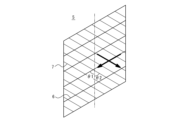
- a plurality of sipes and a plurality of shallow grooves are provided on a surface of the block so as to extend in opposite directions to each other in a tire width direction with respect to one direction in a tire circumferential direction,
- the depth of the shallow groove is smaller than the depth of the sipe,
- the inclination angle ⁇ 1 of the sipe with respect to the tire circumferential direction is greater than 0° and less than 90°,
- the inclination angle ⁇ 2 of the shallow groove with respect to the tire circumferential direction is greater than 0° and less than 90°,
- a pneumatic tire wherein a difference between the inclination angle ⁇ 1 and the inclination angle ⁇ 2 is 30° or less.
- read surface refers to the entire circumferential surface of the contact surface that comes into contact with the road surface when a pneumatic tire is mounted on an applicable rim, inflated to the specified internal pressure, and subjected to the maximum load.
- a “circumferential main groove” and a “widthwise groove” refer to a groove having a groove width (opening width) of 2 mm or more
- a “sipe” refers to a groove having a sipe width such that a portion of the groove is closed when the tire is in contact with the ground, for example, a sipe width of 0.3 mm or more and 0.6 mm or less.
- the "depth” of the sipes or shallow grooves refers to the maximum depth when the pneumatic tire is mounted on an applicable rim, inflated to a specified internal pressure, and no load is applied.
- the "inclination angle" of the sipes and shallow grooves means the inclination angle of a virtual line connecting the end points of the sipes and shallow grooves with respect to the tire circumferential direction when the sipes and shallow grooves are not linear in plan view.
- the sipes and shallow grooves are measured in the opposite direction to the tire circumferential direction with respect to the tire width direction (see FIG. 1).
- the term "applicable rim” refers to a standard rim for an applicable size that is an industrial standard effective in the region where the tire is manufactured and used, and is described or will be described in the future in the JATMA YEAR BOOK of the Japan Automobile Tire Manufacturers Association (JATMA) in Japan, the STANDARDS MANUAL of the European Tire and Rim Technical Organization (ETRTO) in Europe, the YEAR BOOK of the Tire and Rim Association, Inc. (TRA) in the United States, etc. (Measuring Rim in the STANDARDS MANUAL of ETRTO, Design Rim in the YEAR BOOK of TRA).
- rim refers to a rim having a width corresponding to the bead width of a tire (i.e., the "rim” of the above “wheel” includes not only current sizes but also sizes that may be included in the above industry standard in the future. Examples of “sizes to be described in the future” include sizes described as “FUTURE DEVELOPMENTS” in the 2013 edition of ETRTO). However, in the case of a size not described in the above industry standard, the term refers to a rim having a width corresponding to the bead width of a tire.
- the "specified internal pressure” refers to the air pressure (maximum air pressure) corresponding to the maximum load capacity of a single wheel for the applicable size and ply rating as described in the above-mentioned JATMA etc., and in the case of a size not described in the above-mentioned industrial standards, the “specified internal pressure” refers to the air pressure (maximum air pressure) corresponding to the maximum load capacity specified for each vehicle on which the tire is mounted. Moreover, the “maximum load” refers to the load corresponding to the maximum load capacity.
- the terms “groove width” and “sipe width” refer to the opening width when a pneumatic tire is mounted on an applicable rim, inflated to a specified internal pressure, and no load is applied.
- the present invention provides a pneumatic tire with improved grip performance on ice.
- FIG. 1 is a development view that illustrates a tread pattern of a pneumatic tire according to one embodiment of the present invention.
- 1 is a partial cross-sectional view in the tire width direction showing one half in the tire width direction of a pneumatic tire according to one embodiment of the present invention.
- FIG. 2 is a diagram for explaining a tread pattern of an embodiment.
- FIG. 1 is a development view showing a schematic of a tread pattern of a pneumatic tire (hereinafter also simply referred to as a tire) according to one embodiment of the present invention.
- the internal structure of the tire is not particularly limited, but according to convention, the tire can have a pair of bead portions, a pair of sidewalls connected to the bead portions, and a tread portion connected to the sidewall portions. Furthermore, the tire can have a carcass that toroidally spans the pair of bead portions, and a reinforcing layer such as a belt on the radially outer side of the crown portion of the carcass.
- this tire has multiple circumferential main grooves 2 that extend in the circumferential direction of the tire on the tread surface 1 of the tread portion, and multiple land portions 3 are defined between the circumferential main grooves 2 or between the circumferential main grooves 2 and the tread edge TE.
- the circumferential main groove 2a is located in one half in the tire width direction bounded by the tire equatorial plane CL
- the circumferential main groove 2b extends on the tire equatorial plane CL
- the circumferential main groove 2c is located in the other half in the tire width direction bounded by the tire equatorial plane CL.
- the number of circumferential main grooves 2 is not limited to three, and may be any number.
- the circumferential main grooves 2 each extend straight in the tire circumferential direction, but may extend in a zigzag, bent, or curved shape.
- the circumferential main grooves 2 extend in the tire circumferential direction (without inclination), but may extend at an inclination angle of 5° or less with respect to the tire circumferential direction.
- the groove width (opening width) of the circumferential main groove 2 may be, for example, 2 mm to 12 mm.
- the groove depth (maximum depth) of the circumferential main groove 2 may be, for example, 5 mm to 12 mm.
- land portions 3 are formed, with land portions 3a and 3b located in one half in the tire width direction bounded by the tire equatorial plane CL, and land portions 3c and 3d located in the other half in the tire width direction bounded by the tire equatorial plane CL.
- the number of land portions 3 corresponds to the number of circumferential main grooves 2, and may be three or more. Also, any of the land portions 3 may be located on the tire equatorial plane CL.
- Each land portion 3 is provided with a plurality of widthwise grooves 4 extending in the tire width direction.
- the plurality of widthwise grooves 4 are arranged at approximately equal intervals in the tire circumferential direction, thereby dividing the land portion 3 into a plurality of blocks 5 (of approximately the same shape).
- all the widthwise grooves 4 extend straight, but they may extend in a zigzag, bent, or curved shape.
- the widthwise grooves 4 may extend in the tire width direction, or may extend at an inclination angle of 60° or less (or 45° or less, or 30° or less) with respect to the tire width direction.
- the groove width (opening width) of the widthwise grooves 4 may be, for example, 2 mm to 12 mm.
- the groove depth (maximum depth) of the widthwise grooves 4 may be, for example, 5 mm to 12 mm.
- the widthwise grooves 4 that divide the land portion 3a and the widthwise grooves 4 that divide the land portion 3b are located on a straight line, and the widthwise grooves 4 that divide the land portion 3c and the widthwise grooves 4 that divide the land portion 3d are located on a straight line. With this configuration, the drainage performance can be further improved.
- the width direction groove 4 that divides the land portion 3a and the width direction groove 4 that divides the land portion 3b do not have to be located on a straight line (their imaginary extension lines may be shifted from each other in the tire circumferential direction), and the width direction groove 4 that divides the land portion 3c and the width direction groove 4 that divides the land portion 3d do not have to be located on a straight line (their imaginary extension lines may be shifted from each other in the tire circumferential direction).
- the width direction groove 4 located in one half of the tire width direction with the tire equatorial plane CL as the boundary and the width direction groove 4 located in the other half of the tire width direction are inclined in opposite directions in the tire circumferential direction with respect to the tire width direction, but they may be inclined in the same direction in the tire circumferential direction with respect to the tire width direction.
- a plurality of blocks 5 are defined by a plurality of circumferential main grooves 2 extending in the tire circumferential direction and a plurality of widthwise grooves 4 extending in the tire width direction.
- the blocks 5 are approximately parallelogram-shaped in a plan view, but are not limited to this shape.
- a number of sipes 6 and a number of shallow grooves 7 are provided on the surface of the block 5 so as to extend in opposite directions in the tire width direction with respect to one direction in the tire circumferential direction.
- the sipes 6 and the shallow grooves 7 intersect with each other.
- sipes 6 are arranged in each block 5.
- the number of sipes 6 may be any number, and is not limited to four.
- the four sipes 6 are arranged at equal intervals in the circumferential direction of the tire so that the block pieces divided by the sipes 6 are approximately the same size.
- the sipes 6 do not necessarily have to be arranged at equal intervals in the circumferential direction of the tire.
- the sipes 6 are flat sipes that extend linearly in a plan view, but may extend in a zigzag pattern.
- the sipes 6 may be so-called three-dimensional sipes in which the inner wall surface of the sipe is uneven along the sipe depth direction. In this example, both ends of the sipe 6 open into the circumferential main groove 2, but either one or both ends may terminate within the block 5.
- the inclination angle ⁇ 1 of the sipes 6 with respect to the tire circumferential direction is greater than 0° and less than 90°.
- the inclination angle ⁇ 1 is preferably 45° or greater, more preferably 60° or greater, and even more preferably 75° or greater.
- the sipes 6 have the same inclination angle with respect to the tire circumferential direction as the widthwise grooves 4, but they can be different.
- the sipe depth (maximum depth) of the sipe 6 can be, for example, 5 to 8 mm.
- 15 shallow grooves 7 are arranged in each block 5.
- the number of shallow grooves 7 may be any number, and is not limited to 15.
- the 15 shallow grooves 7 are arranged at equal intervals in the tire circumferential direction so that the block pieces divided by the shallow grooves 7 are approximately the same size.
- the shallow grooves 7 may have a pitch interval of 1.0 to 3.0 mm in the tire circumferential direction.
- the shallow grooves 7 do not necessarily have to be arranged at equal intervals in the tire circumferential direction.
- the shallow grooves 7 extend linearly in a plan view, but may extend in a zigzag manner. In this example, both ends of the shallow grooves 7 open into the circumferential main groove 2, but either one or both ends may terminate within the block 5.
- the inclination angle ⁇ 2 of the shallow groove 7 with respect to the tire circumferential direction is greater than 0° and less than 90°.
- the inclination angle ⁇ 2 is preferably 45° or greater, more preferably 60° or greater, and even more preferably 75° or greater.
- the groove width (opening width) of the shallow groove 7 is preferably 0.75 to 1.0 times the sipe width (opening width) of the sipe 6.
- the groove width (opening width) of the shallow groove 7 can be, for example, 0.3 to 0.4 mm.
- the groove depth (maximum depth) of the shallow groove 7 is smaller than the depth (maximum depth) of the sipe 6.
- the groove depth (maximum depth) of the shallow groove 7 can be, for example, 0.1 to 0.3 mm.
- the difference between the tilt angle ⁇ 1 and the tilt angle ⁇ 2 is 30° or less (the absolute value of ⁇ 1- ⁇ 2 is 30° or less). In addition, it is preferable that the difference between the tilt angle ⁇ 1 and the tilt angle ⁇ 2 is 15° or less.
- a plurality of sipes 6 and a plurality of shallow grooves 7 are provided on the surface of the block 5, and therefore, especially when the tire is new, the water film can be removed by both the sipes 6 and the shallow grooves 7, improving grip performance on ice.
- the sipes 6 and the shallow grooves 7 are provided to extend in opposite directions in the tire width direction with respect to one direction in the tire circumferential direction, and the magnitude of the difference between the inclination angle ⁇ 1 and the inclination angle ⁇ 2 is 30° or less, so that water flows uniformly through the sipes 6 and the shallow grooves 7, as illustrated in Fig.
- the drainage function is improved, and grip performance on ice can be further improved.
- the edge component in the tire width direction (edge component in the tire circumferential direction) caused by the sipe 6 will be reduced.
- the inclination angle ⁇ 1 is 90°, the edge component in the tire circumferential direction (edge component in the tire width direction) caused by the sipe 6 will be reduced.
- the inclination angle ⁇ 2 is 0°, the edge component in the tire width direction (edge component in the tire circumferential direction) caused by the shallow groove 7 will be reduced.
- the edge component in the tire circumferential direction (edge component in the tire width direction) caused by the shallow groove 7 will be reduced.
- the depth of the shallow grooves 7 is smaller than the depth of the sipes 6, and the shallow grooves 7 can be removed early, for example, by break-in running. As described above, according to the pneumatic tire of the present embodiment, the grip performance on ice can be improved.
- the inclination angle ⁇ 1 is preferably 45° or more, more preferably 60° or more, and even more preferably 75° or more. This is because by increasing the edge component of the sipe 6 in the tire width direction (edge component in the tire circumferential direction), and improving the function of wiping water in the tire circumferential direction, grip performance on ice can be further improved.
- the inclination angle ⁇ 2 is preferably 45° or more, more preferably 60° or more, and even more preferably 75° or more. This is because by increasing the edge component in the tire width direction (edge component in the tire circumferential direction) of the shallow groove 7 and improving the function of wiping water in the tire circumferential direction, grip performance on ice can be further improved.
- the difference between the inclination angle ⁇ 1 and the inclination angle ⁇ 2 be 15° or less, even more preferable that it be 10° or less, particularly preferable that it be 5° or less, and most preferable that it be 0°.
- the difference between the inclination angle ⁇ 1 and the inclination angle ⁇ 2 is greater than 15° and less than 30°, it may be preferable from the viewpoint of ensuring the rigidity of the land portion and improving ground contact by preventing the block pieces defined by the sipes 6 and the shallow grooves 7 from having portions with too small an acute angle.
- the groove width (opening width) of the shallow groove 7 is preferably 0.75 to 1.0 times the sipe width (opening width) of the sipe 6.
- foamed rubber in the tread rubber.
- a configuration can be realized, for example, by forming the cap rubber layer from foamed rubber, i.e., rubber having many closed air bubbles inside. By forming the cap rubber layer that comes into contact with the road surface from foamed rubber in this way, it is possible to improve performance on ice and snow.
- foamed rubber can be molded by adding a foaming agent to a normal rubber compound and applying heat and pressure according to a normal tire manufacturing method.
- FIG. 3 is a partial cross-sectional view in the tire width direction showing one half in the tire width direction of a pneumatic tire according to an embodiment of the present invention.
- the tire may include an RF tag as the communication device 100.
- the RF tag includes an IC chip and an antenna.
- the RF tag may be sandwiched between a plurality of members of the same or different types constituting the tire, for example. In this way, the RF tag can be easily attached during tire production, and the productivity of tires equipped with an RF tag can be improved.
- the RF tag may be sandwiched between a bead filler and another member adjacent to the bead filler.
- the RF tag may be embedded in any of the members constituting the tire.
- the load applied to the RF tag can be reduced compared to when the RF tag is sandwiched between a plurality of members constituting the tire.
- the RF tag may be embedded in a rubber member such as a tread rubber or a side rubber. It is preferable that the RF tag is not placed at a position that is a boundary between members having different rigidities in the periphery length direction, which is a direction along the tire outer surface in a cross-sectional view in the tire width direction. In this way, the RF tag is not placed in a position where distortion is likely to concentrate due to the rigidity step. Therefore, the load applied to the RF tag can be reduced. This can improve the durability of the RF tag.
- the RF tag is not placed in a position that is a boundary between the end of the carcass and a member adjacent to the end of the carcass (e.g., a side rubber, etc.) in a cross-sectional view in the tire width direction.
- the number of RF tags is not particularly limited.
- a tire may include only one RF tag, or may include two or more RF tags.
- an RF tag is illustrated as an example of a communication device, but a communication device different from the RF tag may be used.
- the RF tag may be placed, for example, in the tread portion of the tire. In this way, the RF tag is not damaged by a side cut of the tire.
- the RF tag may be placed, for example, in the center of the tread in the tire width direction.
- the center of the tread is a position in the tread portion where bending is unlikely to concentrate. In this way, the load applied to the RF tag can be reduced. This improves the durability of the RF tag.
- the RF tag may be placed, for example, within a range of 1/2 the tread width with the tire equatorial plane as the center in the tire width direction.
- the RF tag may be placed, for example, at the tread end in the tire width direction. If the position of the reader that communicates with the RF tag is predetermined, the RF tag may be placed, for example, at the tread end on one side closer to the reader. In this example, the RF tag may be placed, for example, within a range of 1/4 the tread width with the tread end as the outer end in the tire width direction.
- the RF tag may be arranged, for example, on the tire cavity side of the carcass, which includes one or more carcass plies that span between the bead portions. In this way, the RF tag is less likely to be damaged by impacts applied from outside the tire, or damage such as side cuts and nail penetration.
- the RF tag may be arranged in close contact with the surface of the carcass on the tire cavity side.
- the RF tag may be arranged, for example, between the carcass and another member located on the tire cavity side of the carcass.
- An example of another member located on the tire cavity side of the carcass is an inner liner that forms the tire inner surface.
- the RF tag may be attached to the tire inner surface facing the tire cavity.
- the RF tag By configuring the RF tag to be attached to the tire inner surface, it is easy to attach the RF tag to the tire and to inspect and replace the RF tag. In other words, the ease of attachment and maintenance of the RF tag can be improved.
- the RF tag by attaching the RF tag to the inner surface of the tire, the RF tag can be prevented from becoming the core of tire failure, compared to a configuration in which the RF tag is embedded in the tire.
- the RF tag may be positioned between the overlapped carcass plies.
- the RF tag may be arranged, for example, in the tread portion of the tire, on the tire radial outside of the belt including one or more belt plies.
- the RF tag may be arranged on the tire radial outside of the belt and in close contact with the belt.
- the RF tag may be arranged on the tire radial outside of the reinforcing belt layer and in close contact with the reinforcing belt layer.
- the RF tag may be embedded in the tread rubber on the tire radial outside of the belt.
- the RF tag By arranging the RF tag on the tire radial outside of the belt in the tread portion of the tire, communication with the RF tag from the outside of the tire in the tire radial direction is less likely to be hindered by the belt. Therefore, it is possible to improve communication with the RF tag from the outside of the tire in the tire radial direction.
- the RF tag may be arranged, for example, in the tire tread portion of the tire, on the tire radial inside of the belt. In this way, the tire radial outside of the RF tag is covered by the belt, so that the RF tag is less likely to be damaged by impacts from the tread surface or nail penetration.
- the RF tag may be placed in the tread portion of the tire, between the belt and the carcass located radially inward of the belt. Also, if the belt has multiple belt plies, the RF tag may be placed in the tread portion of the tire, between any two belt plies. In this way, the outer side of the RF tag in the tire radial direction is covered by one or more belt plies, making the RF tag less susceptible to damage from impacts from the tread surface or nail penetration.
- the RF tag may be arranged, for example, at the sidewall or bead of the tire.
- the RF tag may be arranged, for example, at one sidewall or one bead that is closer to a reader that can communicate with the RF tag. In this way, the communication between the RF tag and the reader can be improved.
- the RF tag may be arranged between the carcass and the side rubber, or between the tread rubber and the side rubber.
- the RF tag may be arranged, for example, in the tire radial direction, between the position where the tire is at its maximum width and the position of the tread surface.
- the communication with the RF tag from the outside of the tire in the tire radial direction can be improved compared to a configuration in which the RF tag is arranged on the inner side in the tire radial direction from the position where the tire is at its maximum width.
- the RF tag may be arranged, for example, on the inner side in the tire radial direction from the position where the tire is at its maximum width. In this way, the RF tag is arranged near the bead portion that has high rigidity. Therefore, the load applied to the RF tag can be reduced. This can improve the durability of the RF tag.
- the RF tag may be arranged at a position adjacent to the bead core in the tire radial direction or tire width direction.
- Distortion is less likely to concentrate near the bead core. This reduces the load on the RF tag. This improves the durability of the RF tag.
- the RF tag is placed radially inward of the maximum tire width and radially outward of the bead core of the bead portion. This improves the durability of the RF tag, and communication between the RF tag and the reader is less likely to be hindered by the bead core, improving the communication performance of the RF tag.
- the RF tag may be sandwiched between the multiple rubber members that make up the side rubber.
- the RF tag may be sandwiched between the bead filler and a member adjacent to the bead filler. In this way, the RF tag can be placed at a position where distortion is less likely to concentrate due to the placement of the bead filler. Therefore, the load on the RF tag can be reduced. This improves the durability of the RF tag.
- the RF tag may be sandwiched between the bead filler and the carcass, for example.
- the portion of the carcass that sandwiches the RF tag together with the bead filler may be located on the outside in the tire width direction relative to the bead filler, or may be located on the inside in the tire width direction.
- the bead filler may also have a portion that is located adjacent to the side rubber. In such a case, the RF tag may be disposed by being sandwiched between the bead filler and the side rubber. Furthermore, the bead filler may have a portion disposed adjacent to the rubber chafer. In such a case, the RF tag may be disposed by being sandwiched between the bead filler and the rubber chafer.
- the RF tag may be arranged, for example, sandwiched between the rubber chafer and the side rubber. In this way, the RF tag can be arranged in a position where distortion is less likely to be concentrated due to the placement of the rubber chafer. This makes it possible to reduce the load on the RF tag. This makes it possible to improve the durability of the RF tag.
- the RF tag may be arranged, for example, sandwiched between the rubber chafer and the carcass. In this way, it makes it possible to reduce the load on the RF tag due to impacts and damage from the rim. This makes it possible to improve the durability of the RF tag.
- the RF tag may be sandwiched between the wire chafer and another adjacent member on the inside or outside of the wire chafer in the tire width direction. This makes it difficult for the position of the RF tag to fluctuate when the tire deforms. This reduces the load applied to the RF tag when the tire deforms. This improves the durability of the RF tag.
- the other member adjacent to the wire chafer on the inside or outside of the tire width direction may be, for example, a rubber member such as a rubber chafer.
- the other member adjacent to the wire chafer on the inside or outside of the tire width direction may be, for example, a carcass.
- a belt reinforcing layer may be further provided on the radially outer side of the belt.
- the belt reinforcing layer may be formed by winding a cord made of polyethylene terephthalate continuously in a spiral shape in the circumferential direction of the tire.
- the cord may be adhesive-treated under a tension of 6.9 x 10⁻² N/tex or more, and may have an elastic modulus of 2.5 mN/dtex% or more at a load of 29.4 N measured at 160°C.
- the belt reinforcing layer may be arranged to cover the entire belt or only both ends of the belt.
- the winding density per unit width of the belt reinforcing layer may differ depending on the position in the width direction. In this way, road noise and flat spots can be reduced without reducing high-speed durability.
- Figure 4 is a development diagram that shows a typical tread pattern of a pneumatic tire assumed in this embodiment.
- a plurality of blocks are partitioned on the tread surface of the tread portion by a plurality of circumferential main grooves extending in the tire circumferential direction and a plurality of widthwise grooves extending in the tire width direction, and a plurality of sipes and a plurality of shallow grooves are provided on the surface of the blocks so as to extend in opposite directions in the tire width direction with respect to one direction in the tire circumferential direction, and the depth of the shallow grooves is smaller than the depth of the sipes.
- the internal structure of the pneumatic tire is the same as that of a general pneumatic tire.
- a single block on the tread surface of the tread portion of the pneumatic tire was focused on, and rubber samples were produced in which the inclination angle ⁇ 2 of the shallow groove with respect to the tire circumferential direction was variously changed in the block, and the friction coefficient on ice was evaluated.
- the block size was 26 mm in circumferential length, 26 mm in width direction, and 8.5 mm in height, with four sipes in the block.
- the shallow grooves were 0.4 mm wide, 0.25 mm deep, and had a circumferential pitch of 2.0 mm.
- the test to evaluate the coefficient of friction on ice was carried out in an experimental equipment shed at an air temperature of -2°C, where a rubber block sample was pressed against an icy road surface sliding at 10 km/h with an average contact pressure of 250 kPa, and the coefficient of friction was measured.
- the test results are shown in Table 1 below, with the evaluation result of Comparative Example 1 being set at 100, and a higher index indicates better performance.
- tread surface 1: tread surface; 2: circumferential main groove; 3: land portion; 4: width direction groove; 5: block, 6: sipe, 7: shallow groove, 100: communication device, CL: tire equatorial plane, TE: tread edge
Landscapes
- Engineering & Computer Science (AREA)
- Mechanical Engineering (AREA)
- Tires In General (AREA)
Abstract
Description
(1)トレッド部の踏面に、タイヤ周方向に延びる複数本の周方向主溝と、タイヤ幅方向に延びる複数本の幅方向溝とにより複数のブロックが区画され、
前記ブロックの表面に、複数本のサイプと、複数本の浅溝とを、タイヤ周方向の一方向に対してタイヤ幅方向の互いに逆向きに延在するように設け、
前記浅溝の深さは、前記サイプの深さよりも小さく、
前記サイプのタイヤ周方向に対する傾斜角度θ1は、0°超90°未満であり、
前記浅溝のタイヤ周方向に対する傾斜角度θ2は、0°超90°未満であり、
前記傾斜角度θ1と前記傾斜角度θ2との差の大きさが、30°以下であることを特徴とする、空気入りタイヤ。
また、「周方向主溝」及び「幅方向溝」は、溝幅(開口幅)が2mm以上の溝をいい、「サイプ」とは、接地時に一部が閉塞する程度のサイプ幅を有するものであり、例えばサイプ幅が0.3mm以上0.6mm以下のものをいう。
また、サイプや浅溝の「深さ」とは、空気入りタイヤを適用リムに装着し、規定内圧を充填し、無負荷とした状態における最大深さをいうものとする。
また、サイプや浅溝の「傾斜角度」は、サイプや浅溝が平面視で直線状でない場合には、端点同士を結んだ仮想線のタイヤ周方向に対する傾斜角度を意味する。また、サイプと浅溝とで、タイヤ幅方向に対してタイヤ周方向の逆向きに計測するものとする(図1参照)。
また、「規定内圧」とは、上記JATMA等に記載されている、適用サイズ・プライレーティングにおける単輪の最大負荷能力に対応する空気圧(最高空気圧)を指し、上記産業規格に記載のないサイズの場合は、「規定内圧」は、タイヤを装着する車両毎に規定される最大負荷能力に対応する空気圧(最高空気圧)をいうものとする。
また、「最大負荷荷重」とは、上記最大負荷能力に対応する荷重をいうものとする。
本明細書において、「溝幅」及び「サイプ幅」は、空気入りタイヤを適用リムに装着し、規定内圧を充填し、無負荷とした状態における開口幅をいうものとする。
図示例では、周方向主溝2は、いずれもタイヤ周方向に真っすぐ延びているが、ジグザグ状、屈曲状、湾曲状に延びることもできる。また、図示例では、周方向主溝2は、タイヤ周方向に(傾斜せずに)延びているが、タイヤ周方向に対して5°以下の傾斜角度で傾斜して延びることもできる。周方向主溝2の溝幅(開口幅)は、例えば、2mm~12mmとすることができる。周方向主溝2の溝深さ(最大深さ)は、例えば、5mm~12mmとすることができる。
図示例では、幅方向溝4は、いずれも真っすぐ延びているが、ジグザグ状、屈曲状、湾曲状に延びることもできる。また、幅方向溝4は、タイヤ幅方向に延びることができ、あるいは、タイヤ幅方向に対して60°以下(又は45°以下、又は30°以下)の傾斜角度で傾斜して延びることもできる。幅方向溝4の溝幅(開口幅)は、例えば、2mm~12mmとすることができる。幅方向溝4の溝深さ(最大深さ)は、例えば、5mm~12mmとすることができる。また、図示例では、陸部3aを区画する幅方向溝4と陸部3bを区画する幅方向溝4とが直線上に位置し、また、陸部3cを区画する幅方向溝4と陸部3dを区画する幅方向溝4とが直線上に位置している。このような構成によれば、排水性をより一層高めることができる。一方で、陸部3aを区画する幅方向溝4と陸部3bを区画する幅方向溝4とが直線上に位置していなくても(仮想的な延長線が互いにタイヤ周方向にずれていても)良く、また、陸部3cを区画する幅方向溝4と陸部3dを区画する幅方向溝4とが直線上に位置していなくても(仮想的な延長線が互いにタイヤ周方向にずれていても)良い。また、図示例では、タイヤ赤道面CLを境界とするタイヤ幅方向の一方の半部に位置する幅方向溝4と、タイヤ幅方向の他方の半部に位置する幅方向溝4とが、タイヤ幅方向に対してタイヤ周方向の逆向きに傾斜しているが、タイヤ幅方向に対してタイヤ周方向の同じ方向に傾斜しても良い。
以下、本実施形態の空気入りタイヤの作用効果について説明する。
ここで、上記傾斜角度θ1が0°だとサイプ6によるタイヤ幅方向のエッジ成分(タイヤ周方向に対するエッジ成分)が少なくなってしまう。また、上記傾斜角度θ1が90°だとサイプ6によるタイヤ周方向のエッジ成分(タイヤ幅方向に対するエッジ成分)が少なくなってしまう。同様に、上記傾斜角度θ2が0°だと浅溝7によるタイヤ幅方向のエッジ成分(タイヤ周方向に対するエッジ成分)が少なくなってしまう。また、上記傾斜角度θ2が90°だと浅溝7によるタイヤ周方向のエッジ成分(タイヤ幅方向に対するエッジ成分)が少なくなってしまう。
なお、浅溝7の深さは、サイプ6の深さよりも小さく、浅溝7は、例えば慣らし走行により早期に除去され得るものである。
以上のように、本実施形態の空気入りタイヤによれば、氷上グリップ性能を向上させることができる。
なお、上記傾斜角度θ1と上記傾斜角度θ2との差の大きさが15°超30°以下である場合についても、サイプ6と浅溝7により区画されるブロック片に鋭角の角度が小さすぎる部分が生じないようにして、陸部の剛性を確保し、接地性を向上させる観点から好ましい場合もある。
図3は、本発明の一実施形態にかかる空気入りタイヤのタイヤ幅方向の一方の半部を示す、タイヤ幅方向部分断面図である。タイヤは、通信装置100としてのRFタグを備えてよい。RFタグは、ICチップとアンテナとを備える。RFタグは、例えば、タイヤを構成する同種又は異種の複数の部材の間の位置に挟み込まれて配置されてよい。このようにすることで、タイヤ生産時にRFタグを取り付け易く、RFタグを備えるタイヤの生産性を向上させることができる。本例では、RFタグは、例えば、ビードフィラーと、ビードフィラーに隣接するその他の部材と、の間に挟み込まれて配置されてよい。RFタグは、タイヤを構成するいずれかの部材内に埋設されていてもよい。このようにすることで、タイヤを構成する複数の部材の間の位置に挟み込まれて配置される場合と比較して、RFタグに加わる負荷を低減できる。これにより、RFタグの耐久性を向上させることができる。本例では、RFタグは、例えば、トレッドゴム、サイドゴム等のゴム部材内に埋設されてよい。RFタグは、タイヤ幅方向断面視でのタイヤ外面に沿う方向であるペリフェリ長さ方向において、剛性の異なる部材の境界となる位置に、配置されないことが好ましい。このようにすることで、RFタグは、剛性段差に基づき歪みが集中し易い位置に、配置されない。そのため、RFタグに加わる負荷を低減できる。これにより、RFタグの耐久性を向上させることができる。本例では、RFタグは、例えば、タイヤ幅方向断面視でカーカスの端部と、このカーカスの端部に隣接する部材(例えばサイドゴム等)と、の境界となる位置に配置されないことが好ましい。RFタグの数は特に限定されない。タイヤは、1個のみのRFタグを備えてもよく、2個以上のRFタグを備えてもよい。ここでは、通信装置の一例として、RFタグを例示説明しているが、RFタグとは異なる通信装置であってもよい。

5:ブロック、 6:サイプ、 7:浅溝、 100:通信装置、
CL:タイヤ赤道面、 TE:トレッド端
Claims (4)
- トレッド部の踏面に、タイヤ周方向に延びる複数本の周方向主溝と、タイヤ幅方向に延びる複数本の幅方向溝とにより複数のブロックが区画され、
前記ブロックの表面に、複数本のサイプと、複数本の浅溝とを、タイヤ周方向の一方向に対してタイヤ幅方向の互いに逆向きに延在するように設け、
前記浅溝の深さは、前記サイプの深さよりも小さく、
前記サイプのタイヤ周方向に対する傾斜角度θ1は、0°超90°未満であり、
前記浅溝のタイヤ周方向に対する傾斜角度θ2は、0°超90°未満であり、
前記傾斜角度θ1と前記傾斜角度θ2との差の大きさが、30°以下であることを特徴とする、空気入りタイヤ。 - 前記傾斜角度θ1は、45°以上である、請求項1に記載の空気入りタイヤ。
- 前記傾斜角度θ2は、45°以上であり、
前記傾斜角度θ1と前記傾斜角度θ2との差の大きさが、15°以下である、請求項1又は2に記載の空気入りタイヤ。 - 前記浅溝の溝幅は、前記サイプのサイプ幅の0.75~1.0倍である、請求項1~3のいずれか一項に記載の空気入りタイヤ。
Priority Applications (3)
| Application Number | Priority Date | Filing Date | Title |
|---|---|---|---|
| EP23871322.6A EP4596259A4 (en) | 2022-09-26 | 2023-06-16 | TIRES |
| CN202380046130.6A CN119343247A (zh) | 2022-09-26 | 2023-06-16 | 充气轮胎 |
| US18/873,426 US20260070375A1 (en) | 2022-09-26 | 2023-06-16 | Pneumatic tire |
Applications Claiming Priority (2)
| Application Number | Priority Date | Filing Date | Title |
|---|---|---|---|
| JP2022-153038 | 2022-09-26 | ||
| JP2022153038A JP2024047426A (ja) | 2022-09-26 | 2022-09-26 | 空気入りタイヤ |
Publications (1)
| Publication Number | Publication Date |
|---|---|
| WO2024070077A1 true WO2024070077A1 (ja) | 2024-04-04 |
Family
ID=90476864
Family Applications (1)
| Application Number | Title | Priority Date | Filing Date |
|---|---|---|---|
| PCT/JP2023/022497 Ceased WO2024070077A1 (ja) | 2022-09-26 | 2023-06-16 | 空気入りタイヤ |
Country Status (5)
| Country | Link |
|---|---|
| US (1) | US20260070375A1 (ja) |
| EP (1) | EP4596259A4 (ja) |
| JP (1) | JP2024047426A (ja) |
| CN (1) | CN119343247A (ja) |
| WO (1) | WO2024070077A1 (ja) |
Citations (3)
| Publication number | Priority date | Publication date | Assignee | Title |
|---|---|---|---|---|
| WO2004005051A1 (ja) * | 2002-07-05 | 2004-01-15 | The Yokohama Rubber Co.,Ltd. | 氷雪路用空気入りタイヤ |
| US20160311266A1 (en) * | 2013-12-17 | 2016-10-27 | Compagnie Generale Des Etablissements Michelin | Tread band having blocks and fine grooves on the blocks |
| WO2022054930A1 (ja) * | 2020-09-10 | 2022-03-17 | 横浜ゴム株式会社 | タイヤ |
Family Cites Families (5)
| Publication number | Priority date | Publication date | Assignee | Title |
|---|---|---|---|---|
| JP2008221955A (ja) * | 2007-03-09 | 2008-09-25 | Yokohama Rubber Co Ltd:The | 空気入りタイヤ |
| JP5835112B2 (ja) * | 2012-06-05 | 2015-12-24 | 横浜ゴム株式会社 | 空気入りタイヤ |
| JP2016107727A (ja) * | 2014-12-03 | 2016-06-20 | 横浜ゴム株式会社 | 空気入りタイヤ |
| DE102015224290A1 (de) * | 2015-12-04 | 2017-06-08 | Continental Reifen Deutschland Gmbh | Fahrzeugluftreifen |
| DE102020214363A1 (de) * | 2020-11-16 | 2022-05-19 | Continental Reifen Deutschland Gmbh | Fahrzeugluftreifen |
-
2022
- 2022-09-26 JP JP2022153038A patent/JP2024047426A/ja active Pending
-
2023
- 2023-06-16 US US18/873,426 patent/US20260070375A1/en active Pending
- 2023-06-16 WO PCT/JP2023/022497 patent/WO2024070077A1/ja not_active Ceased
- 2023-06-16 EP EP23871322.6A patent/EP4596259A4/en active Pending
- 2023-06-16 CN CN202380046130.6A patent/CN119343247A/zh active Pending
Patent Citations (3)
| Publication number | Priority date | Publication date | Assignee | Title |
|---|---|---|---|---|
| WO2004005051A1 (ja) * | 2002-07-05 | 2004-01-15 | The Yokohama Rubber Co.,Ltd. | 氷雪路用空気入りタイヤ |
| US20160311266A1 (en) * | 2013-12-17 | 2016-10-27 | Compagnie Generale Des Etablissements Michelin | Tread band having blocks and fine grooves on the blocks |
| WO2022054930A1 (ja) * | 2020-09-10 | 2022-03-17 | 横浜ゴム株式会社 | タイヤ |
Non-Patent Citations (1)
| Title |
|---|
| See also references of EP4596259A4 * |
Also Published As
| Publication number | Publication date |
|---|---|
| JP2024047426A (ja) | 2024-04-05 |
| CN119343247A (zh) | 2025-01-21 |
| EP4596259A4 (en) | 2025-12-31 |
| US20260070375A1 (en) | 2026-03-12 |
| EP4596259A1 (en) | 2025-08-06 |
Similar Documents
| Publication | Publication Date | Title |
|---|---|---|
| EP2818333B1 (en) | Pneumatic tire | |
| EP3284617B1 (en) | Run-flat tire | |
| EP2923859B1 (en) | Pneumatic tire | |
| WO2014126048A1 (ja) | 空気入りタイヤ | |
| CN111511586B (zh) | 可镶钉轮胎及充气轮胎 | |
| JP2023010598A (ja) | タイヤ | |
| US12214622B2 (en) | Pneumatic tire | |
| JP2022126526A (ja) | タイヤ | |
| WO2024218995A1 (ja) | 空気入りタイヤ | |
| EP3020573B1 (en) | Pneumatic tire | |
| WO2024070077A1 (ja) | 空気入りタイヤ | |
| JP2023092438A (ja) | タイヤ | |
| EP4714682A1 (en) | Tire | |
| EP4699820A1 (en) | Pneumatic tire | |
| EP4699821A1 (en) | Pneumatic tire | |
| US20260109177A1 (en) | Tire | |
| JP2025083949A (ja) | 空気入りタイヤ | |
| WO2024218994A1 (ja) | 空気入りタイヤ | |
| JP7633484B2 (ja) | タイヤ | |
| EP4596260A1 (en) | Pneumatic tire | |
| JP7599931B2 (ja) | タイヤ | |
| CN109421436A (zh) | 充气轮胎 | |
| JP2024173378A (ja) | 空気入りタイヤ | |
| WO2025248829A1 (ja) | タイヤ | |
| JP2022012510A (ja) | タイヤ |
Legal Events
| Date | Code | Title | Description |
|---|---|---|---|
| 121 | Ep: the epo has been informed by wipo that ep was designated in this application |
Ref document number: 23871322 Country of ref document: EP Kind code of ref document: A1 |
|
| WWE | Wipo information: entry into national phase |
Ref document number: 202380046130.6 Country of ref document: CN Ref document number: 18873426 Country of ref document: US |
|
| WWP | Wipo information: published in national office |
Ref document number: 202380046130.6 Country of ref document: CN |
|
| WWE | Wipo information: entry into national phase |
Ref document number: 2023871322 Country of ref document: EP |
|
| NENP | Non-entry into the national phase |
Ref country code: DE |
|
| ENP | Entry into the national phase |
Ref document number: 2023871322 Country of ref document: EP Effective date: 20250428 |
|
| WWP | Wipo information: published in national office |
Ref document number: 2023871322 Country of ref document: EP |
|
| WWP | Wipo information: published in national office |
Ref document number: 18873426 Country of ref document: US |