WO2024080271A1 - システム、サーバ、車両および方法 - Google Patents
システム、サーバ、車両および方法 Download PDFInfo
- Publication number
- WO2024080271A1 WO2024080271A1 PCT/JP2023/036691 JP2023036691W WO2024080271A1 WO 2024080271 A1 WO2024080271 A1 WO 2024080271A1 JP 2023036691 W JP2023036691 W JP 2023036691W WO 2024080271 A1 WO2024080271 A1 WO 2024080271A1
- Authority
- WO
- WIPO (PCT)
- Prior art keywords
- vehicle
- determination unit
- contact
- obstacle
- guide
- Prior art date
- Legal status (The legal status is an assumption and is not a legal conclusion. Google has not performed a legal analysis and makes no representation as to the accuracy of the status listed.)
- Ceased
Links
Images






Classifications
-
- G—PHYSICS
- G05—CONTROLLING; REGULATING
- G05D—SYSTEMS FOR CONTROLLING OR REGULATING NON-ELECTRIC VARIABLES
- G05D1/00—Control of position, course, altitude or attitude of land, water, air or space vehicles, e.g. using automatic pilots
- G05D1/20—Control system inputs
- G05D1/24—Arrangements for determining position or orientation
- G05D1/241—Means for detecting physical contact, e.g. touch sensors or bump sensors
-
- G—PHYSICS
- G05—CONTROLLING; REGULATING
- G05D—SYSTEMS FOR CONTROLLING OR REGULATING NON-ELECTRIC VARIABLES
- G05D1/00—Control of position, course, altitude or attitude of land, water, air or space vehicles, e.g. using automatic pilots
- G05D1/20—Control system inputs
- G05D1/22—Command input arrangements
- G05D1/221—Remote-control arrangements
- G05D1/225—Remote-control arrangements operated by off-board computers
-
- G—PHYSICS
- G05—CONTROLLING; REGULATING
- G05D—SYSTEMS FOR CONTROLLING OR REGULATING NON-ELECTRIC VARIABLES
- G05D1/00—Control of position, course, altitude or attitude of land, water, air or space vehicles, e.g. using automatic pilots
- G05D1/20—Control system inputs
- G05D1/24—Arrangements for determining position or orientation
- G05D1/244—Arrangements for determining position or orientation using passive navigation aids external to the vehicle, e.g. markers, reflectors or magnetic means
-
- G—PHYSICS
- G05—CONTROLLING; REGULATING
- G05D—SYSTEMS FOR CONTROLLING OR REGULATING NON-ELECTRIC VARIABLES
- G05D1/00—Control of position, course, altitude or attitude of land, water, air or space vehicles, e.g. using automatic pilots
- G05D1/20—Control system inputs
- G05D1/24—Arrangements for determining position or orientation
- G05D1/247—Arrangements for determining position or orientation using signals provided by artificial sources external to the vehicle, e.g. navigation beacons
- G05D1/249—Arrangements for determining position or orientation using signals provided by artificial sources external to the vehicle, e.g. navigation beacons from positioning sensors located off-board the vehicle, e.g. from cameras
-
- G—PHYSICS
- G05—CONTROLLING; REGULATING
- G05D—SYSTEMS FOR CONTROLLING OR REGULATING NON-ELECTRIC VARIABLES
- G05D1/00—Control of position, course, altitude or attitude of land, water, air or space vehicles, e.g. using automatic pilots
- G05D1/60—Intended control result
- G05D1/646—Following a predefined trajectory, e.g. a line marked on the floor or a flight path
-
- G—PHYSICS
- G05—CONTROLLING; REGULATING
- G05D—SYSTEMS FOR CONTROLLING OR REGULATING NON-ELECTRIC VARIABLES
- G05D2105/00—Specific applications of the controlled vehicles
- G05D2105/45—Specific applications of the controlled vehicles for manufacturing, maintenance or repairing
-
- G—PHYSICS
- G05—CONTROLLING; REGULATING
- G05D—SYSTEMS FOR CONTROLLING OR REGULATING NON-ELECTRIC VARIABLES
- G05D2107/00—Specific environments of the controlled vehicles
- G05D2107/70—Industrial sites, e.g. warehouses or factories
-
- G—PHYSICS
- G05—CONTROLLING; REGULATING
- G05D—SYSTEMS FOR CONTROLLING OR REGULATING NON-ELECTRIC VARIABLES
- G05D2109/00—Types of controlled vehicles
- G05D2109/10—Land vehicles
-
- G—PHYSICS
- G05—CONTROLLING; REGULATING
- G05D—SYSTEMS FOR CONTROLLING OR REGULATING NON-ELECTRIC VARIABLES
- G05D2111/00—Details of signals used for control of position, course, altitude or attitude of land, water, air or space vehicles
- G05D2111/10—Optical signals
Definitions
- the present disclosure relates to a system, a server, a vehicle, and a method.
- Japanese Patent Publication No. 2001-265438 is known as a technical document related to an automated driving system.
- Japanese Patent Publication No. 2001-265438 discloses a technology in which map data including information on guided guidance sections and driving routes is stored in a vehicle's storage device, and the vehicle is controlled so as not to deviate from the driving route.
- map data is stored in the vehicle's storage device as in the conventional technology described above, it may be necessary to simplify the information about the guide contained in the map data. However, if the information about the guide is simplified, it may become difficult to properly execute guide following control, which causes the vehicle to travel so as to follow the guide.
- the purpose of this disclosure is to provide technology that can properly execute guide following control.
- a system includes a position determination unit that determines whether a vehicle is located in a guide area including a guide having an uneven structure provided on a road surface, a contact determination unit that determines whether a wheel of the vehicle is in contact with an obstacle using a detection result of an on-board sensor mounted on the vehicle or a detection result of an external sensor located outside the vehicle, and a control unit that controls traveling of the vehicle according to the determination result of the position determination unit and the determination result of the contact determination unit.
- the control unit executes a first control to make the vehicle travel so as to follow a target trajectory or to stop the vehicle when the position determination unit determines that the vehicle is not located in the guide area and the contact determination unit determines that the wheel of the vehicle is in contact with the obstacle, and executes a second control to make the vehicle travel so as to follow the obstacle when the position determination unit determines that the vehicle is located in the guide area and the contact determination unit determines that the wheel of the vehicle is in contact with the obstacle.
- the vehicle can be made to travel so as to follow the guide.
- the system of the above aspect may further include a direction determination unit that determines the guidance direction of the guide based on the direction of the load that the wheels of the vehicle receive from the guide, and the control unit may cause the vehicle to travel along the guidance direction. According to this type of system, the vehicle can be caused to travel in the direction guided by the guide.
- the control unit may correct the target trajectory so as to be aligned with the guidance direction. According to the system of this embodiment, it is possible to prevent the vehicle from deviating from the guide.
- the position determination unit may determine whether the vehicle is located in the guide area based on the recognition results of a signboard corresponding to the guide area or a road marking corresponding to the guide area, based on an image captured by the vehicle's front camera. According to this type of system, it is possible to easily determine whether or not the vehicle is located in the guide area.
- a server is provided.
- the server includes a position determination unit that determines whether or not a vehicle is located in a guide area including a guide having an uneven structure provided on a road surface, a contact determination unit that determines whether or not a wheel of the vehicle is in contact with an obstacle using a detection result of an on-board sensor mounted on the vehicle or a detection result of an external sensor located outside the vehicle, and a remote control unit that remotely controls the traveling of the vehicle according to the determination result of the position determination unit and the determination result of the contact determination unit.
- the remote control unit executes a first control to make the vehicle travel so as to follow a target trajectory or to stop the vehicle when the position determination unit determines that the vehicle is not located in the guide area and the contact determination unit determines that the wheel of the vehicle is in contact with the obstacle, and executes a second control to make the vehicle travel so as to follow the obstacle when the position determination unit determines that the vehicle is located in the guide area and the contact determination unit determines that the wheel of the vehicle is in contact with the obstacle.
- the server of this embodiment it is possible to make the vehicle travel so as to follow the guide.
- the vehicle includes a position determination unit that determines whether the vehicle is located in a guide area including a guide having an uneven structure provided on a road surface, a contact determination unit that determines whether a wheel of the vehicle is in contact with an obstacle using a detection result of an on-board sensor mounted on the vehicle or a detection result of an external sensor located outside the vehicle, and a driving control unit that controls driving of the vehicle according to the determination result of the position determination unit and the determination result of the contact determination unit.
- the driving control unit executes a first control to make the vehicle run so as to follow a target trajectory or to stop the vehicle when the position determination unit determines that the vehicle is not located in the guide area and the contact determination unit determines that the wheel of the vehicle is in contact with the obstacle, and executes a second control to make the vehicle run so as to follow the obstacle when the position determination unit determines that the vehicle is located in the guide area and the contact determination unit determines that the wheel of the vehicle is in contact with the obstacle.
- the vehicle can be caused to travel so as to follow the guide. (7)
- a fourth aspect of the present disclosure there is provided a method.
- the method includes a position determination step of determining whether or not a vehicle is located in a guide area including a guide having an uneven structure provided on a road surface, a contact determination step of determining whether or not a wheel of the vehicle is in contact with an obstacle using a detection result of an on-board sensor mounted on the vehicle or a detection result of an external sensor located outside the vehicle, and a control step of controlling traveling of the vehicle according to a determination result of the position determination step and a determination result of the contact determination step.
- a first control is executed to make the vehicle travel so as to follow a target trajectory or to stop the vehicle
- a second control is executed to make the vehicle travel so as to follow the obstacle.
- the vehicle can be made to travel so as to follow the guide.
- the present disclosure may be realized in various forms other than a system, a server, a vehicle, and a method, for example, a computer program, a recording medium on which a computer program is recorded, or the like.
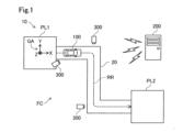
- FIG. 1 is a conceptual diagram showing a configuration of a system according to a first embodiment.
- FIG. 1 is an explanatory diagram showing a configuration of a vehicle according to a first embodiment.
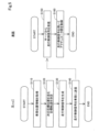
- FIG. 2 is an explanatory diagram showing the configuration of a server according to the first embodiment;
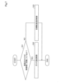
- 4 is a flowchart showing a processing procedure for vehicle travel control according to the first embodiment.
- 11 is a flowchart showing a procedure for determining a position.
- 10 is a flowchart showing a processing procedure of control within a guide area.
- 11 is a flowchart showing a processing procedure for outside-guide-area control.
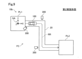
- FIG. 13 is a conceptual diagram showing the configuration of a system according to a second embodiment.
- FIG. 13 is a conceptual diagram showing the configuration of a system according to a second embodiment.
- FIG. 11 is an explanatory diagram showing the configuration of a vehicle according to a second embodiment.
- 10 is a flowchart showing a processing procedure for vehicle travel control according to a second embodiment;
- FIG. 11 is an explanatory diagram showing a configuration of a guide portion according to another embodiment.
- Fig. 1 is a conceptual diagram showing the configuration of a system 10 in a first embodiment.
- Fig. 2 is an explanatory diagram showing a site 90 of a factory FC.
- Fig. 3 is an explanatory diagram showing the configuration of a vehicle 100.
- Fig. 4 is an explanatory diagram showing the configuration of a server 200.
- the system 10 includes a vehicle 100, a server 200, and at least one external sensor 300.
- the vehicle 100 moves by means of wheels WH.
- the wheels WH include caterpillar tracks.
- the vehicle 100 is, for example, a passenger car, a truck, a bus, a two-wheeled vehicle, a four-wheeled vehicle, a tank, a construction vehicle, etc.
- the vehicle 100 is, for example, a gasoline-powered automobile, a hybrid automobile (HEV: Hybrid Electric Vehicle), an electric vehicle (BEV: Battery Electric Vehicle), or a fuel cell electric vehicle (FCEV: Fuel Cell Electric Vehicle).
- HEV Hybrid Electric Vehicle
- BEV Battery Electric Vehicle
- FCEV Fuel Cell Electric Vehicle
- the vehicle 100 is configured to be capable of traveling by unmanned driving.
- Unmanned driving means driving that is not dependent on the driving operation of the passenger. Driving operation means at least one of the operations of "running,” “turning,” and “stopping” of the vehicle 100.
- Unmanned driving is realized by automatic or manual remote control using a device located outside the vehicle 100, or by autonomous control of the vehicle 100.
- a passenger who does not perform driving operations may be on board the vehicle 100 traveling by unmanned driving.
- Passengers who do not perform driving operations include, for example, a person who simply sits in the seat of the vehicle 100, and a person who performs work other than driving operations, such as assembly, inspection, and operation of switches, while riding in the vehicle 100.
- unmanned driving realized by automatic remote control using a device located outside the vehicle 100 and unmanned driving realized by autonomous control of the vehicle 100 are called “automatic driving.” Note that driving by a passenger operating the vehicle may be called “manned driving.”
- remote control includes “full remote control” in which all of the operations of vehicle 100 are completely determined from outside vehicle 100, and “partial remote control” in which some of the operations of vehicle 100 are determined from outside vehicle 100.
- autonomous control includes “full autonomous control” in which vehicle 100 autonomously controls its own operations without receiving any information from devices external to vehicle 100, and “partial autonomous control” in which vehicle 100 autonomously controls its own operations using information received from devices external to vehicle 100.
- the system 10 is used in a factory FC that manufactures vehicles 100.
- the reference coordinate system of the factory FC is the global coordinate system GC. That is, any position in the factory FC is expressed by X, Y, and Z coordinates in the global coordinate system GC.
- the factory FC has a first location PL1 and a second location PL2.
- the first location PL1 and the second location PL2 are connected by a road 20 along which the vehicle 100 can travel.
- a plurality of external sensors 300 are installed along the road 20. The position of each external sensor 300 in the factory FC is adjusted in advance.
- the vehicle 100 moves from the first location PL1 to the second location PL2 through the road 20 by unmanned driving.
- the external sensor 300 is a sensor located outside the vehicle 100.
- the external sensor 300 is a sensor for acquiring the position and orientation of the vehicle 100.
- the external sensor 300 is composed of a camera.
- the camera as the external sensor 300 captures an image of the vehicle 100 passing through the road 20, and outputs the captured image as the detection result.
- the external sensor 300 is equipped with a communication device (not shown) and can communicate with other devices such as the server 200 via wired communication or wireless communication.
- the site 90 of a factory FC is shown.
- the site 90 of the factory FC is referred to as the factory site 90.
- the factory FC is a factory where the vehicle 100 is manufactured.
- the factory FC is not limited to a factory where the vehicle 100 is manufactured, and may be, for example, a factory where the vehicle 100 is maintained.
- the vehicle 100 travels on a road 20 within the factory site 90.
- the road 20 is a driving path along which the vehicle 100 should travel within the factory site 90.
- the road 20 is divided, for example, by white lines formed on the road surface.
- the vehicle 100 travels along a target trajectory 21 for automated driving.
- the target trajectory 21 is set to extend along the road 20.
- the target trajectory 21 may be erroneously set to the center of the road 20 or in a direction deviating from the road 20 due to a sensor anomaly or other influence.
- the factory site 90 includes a guide area 30.
- the factory site 90 includes a plurality of guide areas 30.
- the guide area 30 is an area within the road 20.
- a guidance section 40 is provided in the guide area 30.
- the guidance section 40 has an uneven structure provided on the road surface of the factory site 90.
- the guide area 30 is an area that includes at least one of a recess provided on the road surface and a protrusion provided on the road surface.
- the guidance section 40 includes a pair of guide rails 41 and a guide hole 42. Note that the guide rails 41 may be simply referred to as a guide.
- the guide rails 41 are convex portions formed on the road surface of the factory site 90. When viewed vertically, the pair of guide rails 41 are aligned in the width direction of the road 20. When viewed vertically, the guide rail 41 includes an inclined portion 41a that is inclined with respect to the traveling direction of the road 20, and a parallel portion 41b that is parallel to the traveling direction. The width between the pair of inclined portions 41a gradually decreases as the vehicle progresses in the traveling direction. The parallel portion 41b is located downstream of the inclined portion 41a in the traveling direction.
- the guide rails 41 guide the vehicle 100 along the guidance direction D. When viewed vertically, the guidance direction D is parallel to the extension direction of the guide rails 41.
- the guide hole 42 is a recess formed in the road surface of the factory site 90.
- the guide hole 42 is located downstream of the guide rail 41 in the traveling direction of the road 20. When viewed vertically, the guide hole 42 extends along the width direction of the road 20.
- the guide hole 42 reaches a pair of parallel portions 41b.
- a signboard 51 or road markings 52 corresponding to the guide area 30 are provided.
- the signboard 51 is provided just before the guide area 30 in the traveling direction of the road 20. In other words, the vehicle 100 passes the signboard 51 and then passes the guide area 30.
- the signboard 51 is provided, for example, on the outside of the road 20. For example, letters or symbols for recognizing the guide area 30 are displayed on the signboard 51.
- the road markings 52 are provided just before the guide area 30 in the travel direction of the road 20. In other words, the vehicle 100 passes the guide area 30 after passing the road markings 52.
- the road markings 52 are provided, for example, on the surface of the road 20.
- the road markings 52 are, for example, letters or symbols for recognizing the guide area 30.
- the vehicle 100 includes an ECU 110 for controlling each part of the vehicle 100, a communication device 120 for communicating with external devices such as a server 200 via wireless communication, an on-board sensor 140, and an actuator group 150 including at least one actuator that operates under the control of the ECU 110.
- the actuator group 150 includes a drive actuator 151, a brake actuator 152, and a steering actuator 153.
- the vehicle 100 further includes a front camera 130.
- the front camera 130 is provided inside the passenger compartment of the vehicle 100.
- the front camera 130 captures an image in front of the vehicle 100.
- the front camera 130 transmits information about the captured image to the ECU 110.
- the information about the captured image is transmitted from the ECU 110 to the server 200 via the communication device 120.
- the vehicle 100 does not necessarily have to include the front camera 130.
- the on-vehicle sensor 140 is an internal sensor provided in the vehicle 100.
- the on-vehicle sensor 140 detects the running state of the vehicle 100.
- the on-vehicle sensor 140 includes, for example, a vehicle speed sensor, an acceleration sensor, a yaw rate sensor, a sensor for detecting the driving torque of the vehicle 100, and a sensor for detecting the steering torque of the vehicle 100.
- the on-vehicle sensor 140 detects, for example, the driving torque and steering torque of the vehicle 100 as the running state of the vehicle 100.
- the on-vehicle sensor 140 transmits information relating to the running state of the vehicle 100 to the ECU 110.
- the information relating to the running state of the vehicle 100 is transmitted from the ECU 110 to the server 200 via the communication device 120.
- the drive actuator 151 controls the drive force of the vehicle 100 in response to a driving control signal from the ECU 110. Specifically, the drive actuator 151 controls the amount of air supplied to the engine (throttle opening) to control the drive force of the vehicle 100. If the vehicle 100 is a hybrid vehicle, in addition to the amount of air supplied to the engine, a driving control signal from the ECU 110 is input to the motor serving as a power source to control the drive force. If the vehicle 100 is an electric vehicle, a driving control signal from the ECU 110 is input to the motor serving as a power source to control the drive force. The motor serving as a power source in these cases constitutes the drive actuator 151.
- the brake actuator 152 controls the braking force of the vehicle 100 in response to a driving control signal from the ECU 110. Specifically, the brake actuator 152 controls the brake system in response to the driving control signal from the ECU 110, and controls the braking force applied to the wheels of the vehicle 100.
- the brake system for example, a hydraulic brake system can be used.
- the steering actuator 153 controls the steering torque or steering angle of the vehicle 100 in response to a driving control signal from the ECU 110. Specifically, the steering actuator 153 controls the drive of the assist motor that controls the steering torque or steering angle of the electric power steering system in response to a driving control signal from the ECU 110.
- the ECU 110 is configured as a computer including a processor 111, a memory 112, an input/output interface 113, and an internal bus 114.
- the processor 111, the memory 112, and the input/output interface 113 are connected via the internal bus 114 so as to be able to communicate in both directions.
- the input/output interface 113 is connected to the communication device 120, the front camera 130, the on-board sensor 140, and each of the actuators 151 to 153 of the actuator group 150.
- the processor 111 functions as the driving control unit 115 by executing a computer program PG1 that is pre-stored in the memory 112.
- the driving control unit 115 controls the actuator group 150 to drive the vehicle 100.
- the driving control unit 115 can drive the vehicle 100 by controlling the actuator group 150 using the driving control signal received from the server 200.
- the driving control signal is a control signal for driving the vehicle 100.
- the driving control signal includes the acceleration and steering angle of the vehicle 100 as parameters.
- the driving control signal may include the speed of the vehicle 100 as a parameter instead of or in addition to the acceleration of the vehicle 100.
- the server 200 is configured by a computer including a processor 201, a memory 202, an input/output interface 203, and an internal bus 204.
- the processor 201, the memory 202, and the input/output interface 203 are connected via the internal bus 204 so as to be able to communicate in both directions.
- the input/output interface 203 is connected to a communication device 205 for communicating with various devices outside the server 200.
- the communication device 205 can communicate with the vehicle 100 by wireless communication, and can communicate with each external sensor 300 by wired communication or wireless communication.
- the processor 201 functions as a remote control unit 210, a position determination unit 220, a contact determination unit 230, and a direction determination unit 240 by executing a computer program PG2 pre-stored in the memory 202.
- the remote control unit 210 acquires position information of the vehicle 100 using the external sensor 300, generates a driving control signal for controlling the actuator group 150 of the vehicle 100 according to the position information of the vehicle 100, and transmits the driving control signal to the vehicle 100, thereby driving the vehicle 100 by remote control.
- the remote control unit 210 may generate and output not only driving control signals, but also control signals for controlling actuators that operate various accessories provided on the vehicle 100 and various equipment such as wipers, power windows, and lamps. In other words, the remote control unit 210 may operate these various equipment and accessories by remote control.
- the position determination unit 220 determines whether or not the vehicle 100 is located in the guide area 30. "The vehicle is located in the guide area” means that the vehicle 100 is located within the guide area 30 or that the vehicle 100 is located near the guide area 30. In this embodiment, guide area information indicating the range of the guide area 30 is pre-stored in the memory 202. The position determination unit 220 determines whether or not the vehicle 100 is located within the range of the guide area 30 based on the guide area information and the position information of the vehicle 100 acquired by the remote control unit 210. Note that the position determination unit 220 may determine that the vehicle 100 is located in the guide area 30 when the vehicle 100 is located within the range of the guide area 30 or near the guide area 30.
- the position determination unit 220 may determine whether or not the vehicle 100 is located in the guide area 30 from the recognition result of the signboard 51 or road marking 52 based on the captured image of the forward camera 130 of the vehicle 100. Specifically, the position determination unit 220 may determine that the vehicle 100 is located in the guide area 30 if the size of the letters or symbols displayed on the signboard 51 or the road marking 52 in the captured image captured by the forward camera 130 is larger than a predetermined value. The position determination unit 220 recognizes the signboard 51 or road marking 52 appearing in the captured image by well-known image processing methods such as edge extraction, noise removal, pattern matching, deep learning, etc.
- the contact determination unit 230 determines whether the wheel WH of the vehicle 100 is in contact with an obstacle based on the detection result of the on-board sensor 140. Specifically, the contact determination unit 230 determines that the wheel WH is in contact with an obstacle when, for example, the difference between the driving torque of the vehicle 100, the steering torque of the vehicle 100, or the driving torque of the assist motor, etc. and an assumed value is greater than a predetermined value. In a form in which the vehicle 100 is equipped with a front camera 130, the contact determination unit 230 may determine that the wheel WH is in contact with an obstacle when, for example, the difference between the orientation of the vehicle 100 and an assumed value in the image captured by the front camera 130 is greater than a predetermined value.
- the contact determination unit 230 determines that the wheel WH is in contact with an obstacle when, for example, the difference between the vehicle speed, acceleration, yaw rate, etc. of the vehicle 100 and an assumed value is greater than a predetermined value.
- Each of the above assumed values may be a value set in advance.
- Each of the above assumed values is a value obtained by sequentially calculating the torque generated when it is assumed that the vehicle 100 is traveling on a smooth road surface, based on the vehicle state, such as the vehicle speed or steering angle of the vehicle 100.
- the direction determination unit 240 determines the guiding direction D of the guide rail 41 based on the direction of the load that the wheel WH receives from the guide rail 41.
- the direction determination unit 240 estimates the magnitude and direction of the disturbance torque that is generated due to the load that the wheel WH receives from the guide rail 41 based on the current steering angle and the driving torque of the assist motor controlled by the electric power steering system.
- the direction determination unit 240 determines the guiding direction D based on the magnitude and direction of the disturbance torque.
- the remote control unit 210 remotely controls the traveling of the vehicle 100 based on the judgment results of the position judgment unit 220 and the judgment results of the contact judgment unit 230. Specifically, the remote control unit 210 executes target trajectory tracking control when the position judgment unit 220 judges that the vehicle 100 is not located in the guide area 30 and the contact judgment unit 230 judges that the wheel WH is in contact with an obstacle. In the target trajectory tracking control, the remote control unit 210 causes the vehicle 100 to travel so as to follow the target trajectory 21, treating the obstacle as a disturbance. In the target trajectory tracking control, the remote control unit 210 causes the vehicle 100 to travel so as to overcome the obstacle. In the target trajectory tracking control, the remote control unit 210 does not execute control of the steering angle to avoid the obstacle.
- the remote control unit 210 executes guide following control when the position determination unit 220 determines that the vehicle 100 is located in the guide area 30 and the contact determination unit 230 determines that the wheel WH is contacting an obstacle. In the guide following control, the remote control unit 210 causes the vehicle 100 to travel so as to follow the guide rail 41, which is the obstacle. In the guide following control, the remote control unit 210 causes the vehicle 100 to travel so as not to go over the guide rail 41. In the guide following control, the remote control unit 210 executes control of the steering angle to avoid the guide rail 41.
- the remote control unit 210 causes the vehicle 100 to travel along the guide direction D of the guide rail 41 determined by the direction determination unit 240.
- the remote control unit 210 changes the steering angle toward the guide direction D determined by the direction determination unit 240.
- the remote control unit 210 changes the steering angle so that the disturbance torque generated due to the load that the wheel WH receives from the guide rail 41 is reduced.
- the remote control unit 210 continues to change the steering angle until the disturbance torque becomes equal to or less than a predetermined value. In this way, the vehicle 100 travels along the guide direction D.
- the vehicle 100 may travel with the wheel WH in contact with the guide rail 41.
- the remote control unit 210 may temporarily stop the vehicle 100 when the wheel WH abuts against the guide hole 42.
- the remote control unit 210 corrects the target trajectory 21 to follow the guidance direction D.
- the guidance direction D differs from the target trajectory 21 when, for example, the angle between the guidance direction D and the target trajectory 21 is equal to or greater than a predetermined angle.
- the guidance direction D differs from the target trajectory 21 when, for example, the distance between the guide rail 41 and the target trajectory 21 in the width direction of the road 20 is equal to or greater than a predetermined distance.
- the predetermined angle and the predetermined distance are not particularly limited and can be set to any value in advance.
- the predetermined angle and the predetermined distance can be determined in advance based on, for example, the width of the vehicle 100 and the width of the road 20, etc.
- the target trajectory 21 may include a deviation area 21a.
- the deviation area 21a is located within the guide area 30.
- the deviation area 21a is inclined with respect to the traveling direction of the road 20.
- the deviation area 21a is inclined with respect to the guidance direction D.
- the angle between the guidance direction D and the deviation area 21a is equal to or greater than a predetermined angle.
- the distance between one guide rail 41 and the target trajectory 21 is equal to or greater than a predetermined distance.
- the deviation area 21a is different from the guidance direction D. If the vehicle 100 travels along the deviation area 21a, it may deviate from the road 20.
- the remote control unit 210 corrects the deviation area 21a to a correction area 21b.
- the extension direction of the correction area 21b is approximately the same as the guidance direction D.
- FIG. 5 is a flowchart showing the processing procedure for driving control of the vehicle 100 in this embodiment.
- the processor 201 of the server 200 functions as the remote control unit 210 by executing the computer program PG2.
- the processor 111 of the vehicle 100 functions as the driving control unit 115 by executing the computer program PG1.
- step S110 the remote control unit 210 acquires vehicle position information of the vehicle 100 using the detection results output from the external sensor 300.
- the vehicle position information is position information that is the basis for generating a driving control signal.
- the vehicle position information includes the position and orientation of the vehicle 100 in the global coordinate system GC of the factory FC.
- the remote control unit 210 acquires the vehicle position information using an image captured by a camera, which is the external sensor 300.
- the remote control unit 210 detects the outer shape of the vehicle 100 from the captured image, calculates the coordinates of the positioning point of the vehicle 100 in the coordinate system of the captured image, i.e., the local coordinate system, and converts the calculated coordinates into coordinates in the global coordinate system GC, thereby acquiring the position of the vehicle 100.
- the outer shape of the vehicle 100 contained in the captured image can be detected, for example, by inputting the captured image into a detection model DM that utilizes artificial intelligence.
- the detection model DM is prepared, for example, inside or outside the system 10, and is stored in advance in the memory 202 of the server 200.
- the detection model DM can be, for example, a trained machine learning model that has been trained to realize either semantic segmentation or instance segmentation.
- a convolutional neural network hereinafter, CNN
- the learning dataset includes, for example, a plurality of training images including the vehicle 100, and labels indicating whether each region in the training images indicates the vehicle 100 or a region other than the vehicle 100.
- the CNN it is preferable to update the parameters of the CNN by backpropagation so as to reduce the error between the output result of the detection model DM and the label.
- the remote control unit 210 can obtain the orientation of the vehicle 100 by estimating the orientation based on the orientation of the movement vector of the vehicle 100 calculated from the positional change of the feature points of the vehicle 100 between frames of the captured image using, for example, an optical flow method.
- the remote control unit 210 determines the target position to which the vehicle 100 should next head, and the target trajectory 21 along which the vehicle 100 should move from the current location to the target position.
- the target position is represented by X, Y, and Z coordinates in the global coordinate system GC.
- a reference route RR which is the route the vehicle 100 should travel, is stored in advance in the memory 202 of the server 200. The route is represented by nodes indicating the departure point, nodes indicating passing points, nodes indicating the destination, and links connecting the nodes.
- the remote control unit 210 uses the vehicle position information and the reference route RR to determine the target position to which the vehicle 100 should next head.
- the remote control unit 210 determines a target position on the reference route RR that is ahead of the current location of the vehicle 100.
- step S130 the remote control unit 210 generates a driving control signal for driving the vehicle 100 toward the determined target position.
- the remote control unit 210 calculates the driving speed of the vehicle 100 from the change in the position of the vehicle 100, and compares the calculated driving speed with the target speed. If the driving speed is lower than the target speed, the remote control unit 210 determines the acceleration so that the vehicle 100 accelerates, and if the driving speed is higher than the target speed, the remote control unit 210 determines the acceleration so that the vehicle 100 decelerates.
- the remote control unit 210 determines the steering angle and acceleration so that the vehicle 100 does not deviate from the reference route RR, and if the vehicle 100 is not located on the reference route RR, in other words, if the vehicle 100 deviates from the reference route RR, the remote control unit 210 determines the steering angle and acceleration so that the vehicle 100 returns to the reference route RR.
- step S140 the remote control unit 210 transmits the generated driving control signal to the vehicle 100.
- the remote control unit 210 repeats the acquisition of vehicle position information, determination of the target position, generation of the driving control signal, and transmission of the driving control signal at a predetermined cycle.
- step S150 the driving control unit 115 receives a driving control signal transmitted from the server 200.
- step S160 the driving control unit 115 uses the received driving control signal to control the actuator group 150, thereby causing the vehicle 100 to drive at the acceleration and steering angle represented in the driving control signal.
- the driving control unit 115 repeats receiving the driving control signal and controlling the actuator group 150 at a predetermined cycle.
- the vehicle 100 can be driven by remote control, and the vehicle 100 can be moved without using transportation equipment such as a crane or conveyor.
- FIG. 6 is a flowchart showing the procedure of the position determination process executed by the processor 201 of the server 200.
- the processor 201 determines whether or not the vehicle 100 is in autonomous driving. If the processor 201 determines that the vehicle 100 is in autonomous driving (step S1: YES), the process proceeds to step S2. If the processor 201 determines that the vehicle 100 is not in autonomous driving (step S1: NO), the process ends. In step S2, the processor 201 determines whether or not the vehicle 100 is located in the guide area 30. If the processor 201 determines that the vehicle 100 is located in the guide area 30 (step S2: YES), the process proceeds to step S3.
- step S2 determines that the vehicle 100 is not located in the guide area 30 (step S2: NO)
- the process proceeds to step S4.
- step S3 the processor 201 executes the in-guide-area control.
- step S4 the processor 201 executes the out-guide-area control.
- FIG. 7 is a flowchart showing the processing procedure for control within the guide area.
- the processor 201 determines whether or not the wheel WH of the vehicle 100 is in contact with an obstacle. If the processor 201 determines that the wheel WH is in contact with an obstacle (step S31: YES), the process proceeds to step S32. If the processor 201 determines that the wheel WH is not in contact with an obstacle (step S31: NO), the process proceeds to step S33.
- step S32 the processor 201 executes guide following control.
- step S33 the processor 201 executes target trajectory following control. Note that the target trajectory following control may be referred to as first control, and the guide following control may be referred to as second control.
- FIG. 8 is a flowchart showing the processing procedure for outside guide area control.
- the processor 201 determines whether or not the wheel WH of the vehicle 100 is in contact with an obstacle. If the processor 201 determines that the wheel WH is in contact with an obstacle (step S41: YES), the processor 201 proceeds to step S42. If the processor 201 determines that the wheel WH is not in contact with an obstacle (step S41: NO), the processor 201 ends the current process.
- step S42 the processor 201 determines whether the load that the vehicle 100 receives from the obstacle is equal to or less than a predetermined threshold.
- the predetermined threshold is determined in advance based on the specifications of the vehicle 100 or the shape of the guide rail 41. For example, the greater the unevenness of the guide rail 41, the greater the predetermined threshold.
- step S42 determines that the load applied to the vehicle 100 from the obstacle is equal to or less than a predetermined threshold (step S42: YES)
- step S43 determines that the load applied to the vehicle 100 from the obstacle is greater than a predetermined threshold
- step S44 executes target trajectory tracking control.
- step S44 the processor 201 executes obstacle avoidance control.
- the obstacle avoidance control is executed by a known technique.
- the target trajectory tracking control may be referred to as a first control, and the obstacle avoidance control may be referred to as a third control.
- the remote control unit 210 executes guide following control with the obstacle as the guide rail 41.
- the guide following control can be executed based on the determination result of whether the wheel WH of the vehicle 100 is contacting an obstacle. Therefore, according to the system 10, the guide following control can be executed appropriately. Furthermore, according to the system 10, the position of the vehicle 100 can be controlled more accurately.
- the system 10 includes a direction determination unit 240 that determines the guide direction D of the guide rail 41 based on the direction of the load that the wheels WH of the vehicle 100 receive from the guide rail 41.
- the remote control unit 210 drives the vehicle 100 so as to follow the guide direction D. This makes it possible to appropriately execute guide following control even when the information about the guide rail 41 included in the guide area 30 is simplified.
- the remote control unit 210 corrects the target trajectory 21 so that it follows the guidance direction D. This makes it possible to more appropriately execute guide following control.
- the position determination unit 220 may determine whether the vehicle 100 is located in the guide area 30 from the recognition results of the signboard 51 or road markings 52 based on the image captured by the front camera 130 of the vehicle 100. This makes it easy to determine whether the vehicle 100 is located in the guide area 30, and allows guide following control to be appropriately executed.
- Fig. 9 is a conceptual diagram showing the configuration of a system 10b in the second embodiment.
- Fig. 10 is an explanatory diagram showing the configuration of a vehicle 100.
- the system 10b in this embodiment differs from the first embodiment in that it does not include a server 200 and that the vehicle 100 runs under the autonomous control of the vehicle 100.
- the other configurations are the same as those in the first embodiment unless otherwise described.
- the processor 111 of the ECU 110 executes a computer program PG1 pre-stored in the memory 112, thereby functioning as a driving control unit 115, a position determination unit 116, a contact determination unit 117, and a direction determination unit 118.
- the driving control unit 115 acquires output results from the external sensor 300, generates driving control signals using the output results, and outputs the generated driving control signals to operate the actuator group 150, thereby enabling the vehicle 100 to drive by autonomous control.
- a detection model DM and a reference route RR are pre-stored in the memory 112.
- the functions of the position determination unit 116, the contact determination unit 117, and the direction determination unit 118 are similar to those of the position determination unit 220, the contact determination unit 230, and the direction determination unit 240 shown in FIG. 4. That is, the position determination unit 116 determines whether or not the vehicle 100 is located in the guide area 30.
- the contact determination unit 117 determines whether or not the wheel WH of the vehicle 100 is in contact with an obstacle.
- the direction determination unit 118 determines the guide direction D of the guide rail 41 based on the direction of the load that the wheel WH of the vehicle 100 receives from the guide rail 41.
- step S210 the driving control unit 115 acquires vehicle position information using the detection result output from the camera, which is the external sensor 300.
- step S220 the driving control unit 115 determines the target position to which the vehicle 100 should next head.
- step S230 the driving control unit 115 generates a driving control signal for driving the vehicle 100 toward the determined target position.
- step S240 the driving control unit 115 controls the actuator group 150 using the generated driving control signal, thereby driving the vehicle 100 according to the parameters represented in the driving control signal.
- the driving control unit 115 repeats the acquisition of vehicle position information, the determination of the target position, the generation of the driving control signal, and the control of the actuators at a predetermined cycle.
- the processes shown in Figures 6 to 8 are executed by the ECU 110 of the vehicle 100. Therefore, as shown in Figure 6, when the vehicle 100 is in autonomous driving and the position determination unit 116 determines that the vehicle 100 is located in the guide area 30, the in-guide area control is executed. When the vehicle 100 is in autonomous driving and the position determination unit 116 does not determine that the vehicle 100 is located in the guide area 30, the out-guide area control is executed. As shown in Figure 7, in the in-guide area control, when the abutment determination unit 117 determines that the wheel WH of the vehicle 100 is in abutment with an obstacle, the guide following control is executed.
- the target trajectory following control is executed.
- the target trajectory tracking control is executed.
- the target trajectory tracking control is executed.
- the obstacle avoidance control is executed.
- the vehicle 100 can be caused to travel so as to follow the guide rail 41.
- the vehicle 100 can be caused to travel so as to follow the guide rail 41 by autonomous control of the vehicle 100, without remote control of the vehicle 100 by the server 200.
- FIG. 12 is an explanatory diagram showing the configuration of the guiding unit 40 in another embodiment.
- the guide rail 41 may be a recess formed on the road surface and extending in the direction in which the vehicle 100 is to be guided.
- the cross section of the guide rail 41 is, for example, V-shaped.
- the remote control unit 210 shown in Fig. 4 or the traveling control unit 115 shown in Fig. 10 may control the steering angle so that the reaction force from the road surface estimated from the steering torque or the lateral acceleration of the vehicle 100 detected by the on-board sensor 140 becomes approximately zero. This allows the lateral position of the vehicle 100 to be accurately adjusted with respect to the guide rail 41.
- the guide following control function of the driving control unit 115 may be turned off when the vehicle 100 is shipped from the factory site 90. This allows the guide following control to be executed only when the vehicle 100 is located within the factory site 90, thereby preventing erroneous execution of driving control when the vehicle 100 is located on a public road.
- At least one of the signboard 51 and the road marking 52 may not be provided on the factory site 90.
- the guide portion 40 does not have to include a guide hole 42.
- the system 10 does not need to include a direction determination unit 240, and the remote control unit 210 does not need to modify the target trajectory 21.
- the system 10b does not need to include a direction determination unit 118, and the driving control unit 115 does not need to modify the target trajectory 21.
- the external sensor 300 is a camera.
- the external sensor 300 does not have to be a camera and may be, for example, a LiDAR (Light Detection And Ranging) sensor.
- the detection result output by the external sensor 300 may be three-dimensional point cloud data representing the vehicle 100.
- the server 200 and the vehicle 100 may acquire vehicle position information by template matching using the three-dimensional point cloud data as the detection result and reference point cloud data prepared in advance.
- the position determination unit 220, 116 determines whether the vehicle 100 is located in the guide area 30 using the vehicle position information acquired using the external sensor 300 and the guide area information indicating the range of the guide area 30. In contrast, the position determination unit 220, 116 may recognize the signboard 51 or the road surface marking 52 using the forward camera 130 mounted on the vehicle 100, and determine whether the vehicle 100 is located in the guide area 30 from the recognition result. If the vehicle 100 is equipped with LiDAR, the position determination unit 220, 116 may recognize the signboard 51 or the road surface marking 52 using the LiDAR, and determine whether the vehicle 100 is located in the guide area 30 from the recognition result.
- the position determination unit 220, 116 may determine whether the vehicle 100 is located in the guide area 30 using an image output from a camera that is the external sensor 300. If the external sensor 300 is a LiDAR, the position determination unit 220, 116 may determine whether or not the vehicle 100 is located in the guide area 30 using three-dimensional point cloud data output from the LiDAR external sensor 300. If the identification number of the external sensor 300 monitoring the guide area 30, among the multiple external sensors 300 installed in the factory site 90, is stored in advance in the memory 202, 112, the position determination unit 220, 116 may determine that the vehicle 100 is located in the guide area 30 when the vehicle 100 is detected by the external sensor 300 monitoring the guide area 30.
- the abutment determination unit 230, 117 uses the detection result of the on-board sensor 140 mounted on the vehicle 100 to determine whether the wheel WH of the vehicle 100 is abutting against the guide rail 41.
- the abutment determination unit 230, 117 may use the detection result of the external sensor 300 to determine whether the wheel WH of the vehicle 100 is abutting against the guide rail 41.
- the abutment determination unit 230, 117 may detect the wheel WH and the guide rail 41 from an image captured by a camera, which is the external sensor 300, and determine whether the wheel WH and the guide rail 41 are abutting against each other based on the positional relationship between the wheel WH and the guide rail 41.
- the server 200 executes the processes from acquiring the vehicle position information to generating the driving control signal.
- at least a part of the processes from acquiring the vehicle position information to generating the driving control signal may be executed by the vehicle 100.
- the following forms (1) to (3) may be used.
- the server 200 may acquire vehicle position information, determine a target position to which the vehicle 100 should next head, and generate a route from the current location of the vehicle 100 represented in the acquired vehicle position information to the target position.
- the server 200 may generate a route to a target position between the current location and the destination, or may generate a route to the destination.
- the server 200 may transmit the generated route to the vehicle 100.
- the vehicle 100 may generate a driving control signal so that the vehicle 100 drives on the route received from the server 200, and control the actuator group 150 using the generated driving control signal.
- the server 200 may acquire vehicle position information and transmit the acquired vehicle position information to the vehicle 100.
- the vehicle 100 may determine a target position to which the vehicle 100 should next head, generate a route from the current location of the vehicle 100 represented in the received vehicle position information to the target position, generate a driving control signal so that the vehicle 100 drives on the generated route, and control the actuator group 150 using the generated driving control signal.
- an internal sensor may be mounted on the vehicle 100, and a detection result output from the internal sensor may be used for at least one of generating a route and generating a driving control signal.
- the internal sensor is a sensor mounted on the vehicle 100.
- the internal sensor may include, for example, a sensor that detects the motion state of the vehicle 100, a sensor that detects the operating state of each part of the vehicle 100, and a sensor that detects the environment around the vehicle 100.
- the internal sensor may include, for example, a camera, LiDAR, a millimeter wave radar, an ultrasonic sensor, a GPS sensor, an acceleration sensor, a gyro sensor, and the like.
- the server 200 may acquire the detection result of the internal sensor and reflect the detection result of the internal sensor in the route when generating a route.
- the vehicle 100 may acquire the detection result of the internal sensor and reflect the detection result of the internal sensor in the driving control signal when generating a driving control signal.
- the vehicle 100 may acquire the detection result of the internal sensor and reflect the detection result of the internal sensor in the route when generating a route.
- the vehicle 100 may acquire the detection result of the internal sensor, and when generating the driving control signal, may reflect the detection result of the internal sensor in the driving control signal.
- the vehicle 100 may be equipped with an internal sensor, and the detection results output from the internal sensor may be used for at least one of generating a route and generating a driving control signal.
- the vehicle 100 may acquire the detection results of the internal sensor, and when generating a route, may reflect the detection results of the internal sensor in the route.
- the vehicle 100 may acquire the detection results of the internal sensor, and when generating a driving control signal, may reflect the detection results of the internal sensor in the driving control signal.
- the vehicle 100 acquires vehicle position information using the detection result of the external sensor 300.
- the vehicle 100 is equipped with an internal sensor, and the vehicle 100 acquires vehicle position information using the detection result of the internal sensor, determines a target position to which the vehicle 100 should next head, generates a route from the current location of the vehicle 100 represented in the acquired vehicle position information to the target position, generates a driving control signal for traveling along the generated route, and controls the actuator group 150 using the generated driving control signal.
- a camera or LiDAR can be used as the internal sensor for acquiring the vehicle position information. In this case, the vehicle 100 can travel without using any of the detection results of the external sensor 300.
- the vehicle 100 may acquire a target arrival time or traffic congestion information from outside the vehicle 100, and reflect the target arrival time or traffic congestion information in at least one of the route and the driving control signal.
- all of the functional configurations of the systems 10 and 10b may be provided in the vehicle 100. That is, the processing performed by systems 10 and 10b in this disclosure may be performed by vehicle 100 alone.
- the server 200 automatically generates a driving control signal to be transmitted to the vehicle 100.
- the server 200 may generate a driving control signal to be transmitted to the vehicle 100 in accordance with the operation of an external operator located outside the vehicle 100.
- the external operator may operate a control device including a display for displaying an image output from the external sensor 300, a steering wheel for remotely controlling the vehicle 100, an accelerator pedal, a brake pedal, and a communication device for communicating with the server 200 via wired or wireless communication, and the server 200 may generate a driving control signal in response to the operation applied to the control device.
- the vehicle 100 may have a configuration capable of moving by unmanned driving, and may be in the form of a platform having the configuration described below, for example.
- the vehicle 100 may have at least an ECU 110 and an actuator group 150 in order to perform the three functions of "running", "turning", and "stopping" by unmanned driving.
- the vehicle 100 may further have a communication device 120. That is, the vehicle 100 capable of moving by unmanned driving may not have at least a part of interior parts such as a driver's seat and a dashboard, may not have at least a part of exterior parts such as a bumper and a fender, and may not have a body shell.
- the remaining parts such as a body shell may be attached to the vehicle 100 before the vehicle 100 is shipped from the factory FC, or the remaining parts such as a body shell may be attached to the vehicle 100 after the vehicle 100 is shipped from the factory FC in a state in which the remaining parts such as the body shell are not attached to the vehicle 100.
- Each part may be attached from any direction, such as the top, bottom, front, rear, right side, or left side of the vehicle 100, and may be attached from the same direction or from different directions. Note that the position can be determined for the platform configuration in the same way as for the vehicle 100 in the first embodiment.
- the vehicle 100 may be manufactured by combining multiple modules.
- a module means a unit composed of multiple parts grouped together according to the location and function of the vehicle 100.
- the platform of the vehicle 100 may be manufactured by combining a front module that constitutes the front part of the platform, a central module that constitutes the central part of the platform, and a rear module that constitutes the rear part of the platform.
- the number of modules that constitute the platform is not limited to three, and may be two or less or four or more.
- parts that constitute parts of the vehicle 100 that are different from the platform may be modularized.
- the various modules may also include any exterior parts such as a bumper or a grill, or any interior parts such as a seat or a console.
- any type of moving body may be manufactured by combining multiple modules.
- a module may be manufactured, for example, by joining multiple parts by welding or a fastener, or may be manufactured by integrally molding at least a part of the parts that constitute the module as one part by casting.
- a molding method for integrally molding one part, especially a relatively large part, is also called giga casting or mega casting.
- the front, center, and rear modules described above may be manufactured using Gigacast.
- (C15) Transporting the vehicle 100 by using the unmanned driving of the vehicle 100 is also called “self-propelled transport".
- the configuration for realizing self-propelled transport is also called a "vehicle remote-controlled autonomous driving transport system”.
- a production method for producing the vehicle 100 by using self-propelled transport is also called “self-propelled production”.
- self-propelled production for example, at a factory FC where the vehicle 100 is manufactured, at least a portion of the transport of the vehicle 100 is realized by self-propelled transport.
Landscapes
- Engineering & Computer Science (AREA)
- Aviation & Aerospace Engineering (AREA)
- Radar, Positioning & Navigation (AREA)
- Remote Sensing (AREA)
- Physics & Mathematics (AREA)
- General Physics & Mathematics (AREA)
- Automation & Control Theory (AREA)
- Traffic Control Systems (AREA)
- Control Of Position, Course, Altitude, Or Attitude Of Moving Bodies (AREA)
Abstract
Description
この形態のシステムによれば、車両をガイドに追従するように走行させることができる。
(2)上記形態のシステムは、前記車両の車輪が前記ガイドから受ける荷重の方向に基づいて、前記ガイドの誘導方向を判定する方向判定部を更に備え、前記制御部は、前記誘導方向に沿うように前記車両を走行させてもよい。
この形態のシステムによれば、車両をガイドの誘導方向に沿って走行させることができる。
(3)上記形態のシステムにおいて、前記制御部は、前記誘導方向が前記目標軌道と異なる場合に、前記誘導方向に沿うように前記目標軌道を修正してもよい。
この形態のシステムによれば、車両がガイドから逸脱して走行することを抑制できる。
(4)上記形態のシステムにおいて、前記位置判定部は、前記車両の前方カメラの撮像画像に基づいて、前記ガイドエリアに対応する看板又は前記ガイドエリアに対応する路面表示の認識結果から前記車両が前記ガイドエリアに位置しているか否かを判定してもよい。
この形態のシステムによれば、車両がガイドエリアに位置しているか否かを簡単に判定することができる。
(5)本開示の第2の形態によれば、サーバが提供される。このサーバは、路面に設けられた凹凸構造を有するガイドを含むガイドエリアに車両が位置しているか否かを判定する位置判定部と、前記車両に搭載されている車載センサの検出結果、または、前記車両の外部に位置している外部センサの検出結果を用いて、前記車両の車輪が障害物に当接しているか否かを判定する当接判定部と、前記位置判定部の判定結果と前記当接判定部の判定結果とに応じて、前記車両の走行を遠隔制御する遠隔制御部と、を備える。前記遠隔制御部は、前記位置判定部により前記車両が前記ガイドエリアに位置していないと判定され、かつ、前記当接判定部により前記車両の車輪が前記障害物に当接していると判定された場合に、前記車両を目標軌道に追従するように走行させ、または、前記車両を停止させる第1制御を実行し、前記位置判定部により前記車両が前記ガイドエリアに位置していると判定され、かつ、前記当接判定部により前記車両の車輪が前記障害物に当接していると判定された場合に、前記障害物に追従するように前記車両を走行させる第2制御を実行する。
この形態のサーバによれば、車両をガイドに追従するように走行させることができる。
(6)本開示の第3の形態によれば、車両が提供される。この車両は、路面に設けられた凹凸構造を有するガイドを含むガイドエリアに前記車両が位置しているか否かを判定する位置判定部と、前記車両に搭載されている車載センサの検出結果、または、前記車両の外部に位置している外部センサの検出結果を用いて、前記車両の車輪が障害物に当接しているか否かを判定する当接判定部と、前記位置判定部の判定結果と前記当接判定部の判定結果とに応じて、前記車両の走行を制御する走行制御部と、を備える。前記走行制御部は、前記位置判定部により前記車両が前記ガイドエリアに位置していないと判定され、かつ、前記当接判定部により前記車両の車輪が前記障害物に当接していると判定された場合に、前記車両を目標軌道に追従するように走行させ、または、前記車両を停止させる第1制御を実行し、前記位置判定部により前記車両が前記ガイドエリアに位置していると判定され、かつ、前記当接判定部により前記車両の車輪が前記障害物に当接していると判定された場合に、前記障害物に追従するように前記車両を走行させる第2制御を実行する。
この形態の車両によれば、車両をガイドに追従するように走行させることができる。
(7)本開示の第4の形態によれば、方法が提供される。この方法は、路面に設けられた凹凸構造を有するガイドを含むガイドエリアに車両が位置しているか否かを判定する位置判定工程と、前記車両に搭載されている車載センサの検出結果、または、前記車両の外部に位置している外部センサの検出結果を用いて、前記車両の車輪が障害物に当接しているか否かを判定する当接判定工程と、前記位置判定工程の判定結果と前記当接判定工程の判定結果とに応じて、前記車両の走行を制御する制御工程と、を備える。前記制御工程では、前記位置判定工程において前記車両が前記ガイドエリアに位置していないと判定され、かつ、前記当接判定工程において前記車両の車輪が前記障害物に当接していると判定された場合に、前記車両を目標軌道に追従するように走行させ、または、前記車両を停止させる第1制御を実行し、前記位置判定工程において前記車両が前記ガイドエリアに位置していると判定され、かつ、前記当接判定工程において前記車両の車輪が前記障害物に当接していると判定された場合に、前記障害物に追従するように前記車両を走行させる第2制御を実行する。
この形態の方法によれば、車両をガイドに追従するように走行させることができる。
本開示は、システム、サーバ、車両および方法以外の種々の形態で実現することも可能である。例えば、コンピュータプログラム、および、コンピュータプログラムが記録された記録媒体などの形態で実現することができる。
図1は、第1実施形態におけるシステム10の構成を示す概念図である。図2は、工場FCの敷地90を示す説明図である。図3は、車両100の構成を示す説明図である。図4は、サーバ200の構成を示す説明図である。図1に示すように、本実施形態では、システム10は、車両100と、サーバ200と、少なくとも1つの外部センサ300とを備えている。
なお、目標軌道追従制御のことを第1制御と呼ぶことがあり、障害物回避制御のことを第3制御と呼ぶことがある。
図9は、第2実施形態におけるシステム10bの構成を示す概念図である。図10は、車両100の構成を示す説明図である。本実施形態におけるシステム10bは、サーバ200を備えていないこと、および、車両100の自律制御により車両100が走行することが第1実施形態とは異なる。その他の構成については、特に説明しない限り、第1実施形態と同じである。
(C1)図12は、他の実施形態における誘導部40の構成を示す説明図である。図12に示すように、ガイドレール41は、路面に形成され、車両100を誘導したい方向に延びる凹部であってもよい。ガイドレール41の断面は、例えばV字状を成している。この場合、図4に示した遠隔制御部210や図10に示した走行制御部115は、操舵トルクから推定された路面からの反力、又は車載センサ140によって検出された車両100の横加速度が略零となるように操舵角を制御してもよい。これにより、ガイドレール41に対する車両100の横位置を正確に合わせることができる。
Claims (7)
- システムであって、
路面に設けられた凹凸構造を有するガイドを含むガイドエリアに車両が位置しているか否かを判定する位置判定部と、
前記車両に搭載されている車載センサの検出結果、または、前記車両の外部に位置している外部センサの検出結果を用いて、前記車両の車輪が障害物に当接しているか否かを判定する当接判定部と、
前記位置判定部の判定結果と前記当接判定部の判定結果とに応じて、前記車両の走行を制御する制御部と、
を備え、
前記制御部は、
前記位置判定部により前記車両が前記ガイドエリアに位置していないと判定され、かつ、前記当接判定部により前記車両の車輪が前記障害物に当接していると判定された場合に、前記車両を目標軌道に追従するように走行させ、または、前記車両を停止させる第1制御を実行し、
前記位置判定部により前記車両が前記ガイドエリアに位置していると判定され、かつ、前記当接判定部により前記車両の車輪が前記障害物に当接していると判定された場合に、前記障害物に追従するように前記車両を走行させる第2制御を実行する、
システム。 - 請求項1に記載のシステムであって、
前記車両の車輪が前記ガイドから受ける荷重の方向に基づいて、前記ガイドの誘導方向を判定する方向判定部を更に備え、
前記制御部は、前記誘導方向に沿うように前記車両を走行させる、システム。 - 請求項2に記載のシステムであって、
前記制御部は、前記誘導方向が前記目標軌道と異なる場合に、前記誘導方向に沿うように前記目標軌道を修正する、システム。 - 請求項1に記載のシステムであって、
前記位置判定部は、前記車両の前方カメラの撮像画像に基づいて、前記ガイドエリアに対応する看板又は前記ガイドエリアに対応する路面表示の認識結果から前記車両が前記ガイドエリアに位置しているか否かを判定する、システム。 - サーバであって、
路面に設けられた凹凸構造を有するガイドを含むガイドエリアに車両が位置しているか否かを判定する位置判定部と、
前記車両に搭載されている車載センサの検出結果、または、前記車両の外部に位置している外部センサの検出結果を用いて、前記車両の車輪が障害物に当接しているか否かを判定する当接判定部と、
前記位置判定部の判定結果と前記当接判定部の判定結果とに応じて、前記車両の走行を遠隔制御する遠隔制御部と、
を備え、
前記遠隔制御部は、
前記位置判定部により前記車両が前記ガイドエリアに位置していないと判定され、かつ、前記当接判定部により前記車両の車輪が前記障害物に当接していると判定された場合に、前記車両を目標軌道に追従するように走行させ、または、前記車両を停止させる第1制御を実行し、
前記位置判定部により前記車両が前記ガイドエリアに位置していると判定され、かつ、前記当接判定部により前記車両の車輪が前記障害物に当接していると判定された場合に、前記障害物に追従するように前記車両を走行させる第2制御を実行する、
サーバ。 - 車両であって、
路面に設けられた凹凸構造を有するガイドを含むガイドエリアに前記車両が位置しているか否かを判定する位置判定部と、
前記車両に搭載されている車載センサの検出結果、または、前記車両の外部に位置している外部センサの検出結果を用いて、前記車両の車輪が障害物に当接しているか否かを判定する当接判定部と、
前記位置判定部の判定結果と前記当接判定部の判定結果とに応じて、前記車両の走行を制御する走行制御部と、
を備え、
前記走行制御部は、
前記位置判定部により前記車両が前記ガイドエリアに位置していないと判定され、かつ、前記当接判定部により前記車両の車輪が前記障害物に当接していると判定された場合に、前記車両を目標軌道に追従するように走行させ、または、前記車両を停止させる第1制御を実行し、
前記位置判定部により前記車両が前記ガイドエリアに位置していると判定され、かつ、前記当接判定部により前記車両の車輪が前記障害物に当接していると判定された場合に、前記障害物に追従するように前記車両を走行させる第2制御を実行する、
車両。 - 方法であって、
路面に設けられた凹凸構造を有するガイドを含むガイドエリアに車両が位置しているか否かを判定する位置判定工程と、
前記車両に搭載されている車載センサの検出結果、または、前記車両の外部に位置している外部センサの検出結果を用いて、前記車両の車輪が障害物に当接しているか否かを判定する当接判定工程と、
前記位置判定工程の判定結果と前記当接判定工程の判定結果とに応じて、前記車両の走行を制御する制御工程と、
を備え、
前記制御工程では、
前記位置判定工程において前記車両が前記ガイドエリアに位置していないと判定され、かつ、前記当接判定工程において前記車両の車輪が前記障害物に当接していると判定された場合に、前記車両を目標軌道に追従するように走行させ、または、前記車両を停止させる第1制御を実行し、
前記位置判定工程において前記車両が前記ガイドエリアに位置していると判定され、かつ、前記当接判定工程において前記車両の車輪が前記障害物に当接していると判定された場合に、前記障害物に追従するように前記車両を走行させる第2制御を実行する、
方法。
Priority Applications (2)
| Application Number | Priority Date | Filing Date | Title |
|---|---|---|---|
| EP23877274.3A EP4603354A4 (en) | 2022-10-14 | 2023-10-10 | SYSTEM, SERVER, VEHICLE AND METHOD |
| CN202380071338.3A CN120076971A (zh) | 2022-10-14 | 2023-10-10 | 系统、服务器、车辆及方法 |
Applications Claiming Priority (4)
| Application Number | Priority Date | Filing Date | Title |
|---|---|---|---|
| JP2022165367 | 2022-10-14 | ||
| JP2022-165367 | 2022-10-14 | ||
| JP2023-174077 | 2023-10-06 | ||
| JP2023174077A JP7810161B2 (ja) | 2022-10-14 | 2023-10-06 | システム、サーバ、車両および方法 |
Publications (1)
| Publication Number | Publication Date |
|---|---|
| WO2024080271A1 true WO2024080271A1 (ja) | 2024-04-18 |
Family
ID=90669598
Family Applications (1)
| Application Number | Title | Priority Date | Filing Date |
|---|---|---|---|
| PCT/JP2023/036691 Ceased WO2024080271A1 (ja) | 2022-10-14 | 2023-10-10 | システム、サーバ、車両および方法 |
Country Status (3)
| Country | Link |
|---|---|
| EP (1) | EP4603354A4 (ja) |
| CN (1) | CN120076971A (ja) |
| WO (1) | WO2024080271A1 (ja) |
Cited By (1)
| Publication number | Priority date | Publication date | Assignee | Title |
|---|---|---|---|---|
| EP4707816A1 (en) * | 2024-09-04 | 2026-03-11 | Toyota Jidosha Kabushiki Kaisha | Inspection method of a vehicle |
Citations (7)
| Publication number | Priority date | Publication date | Assignee | Title |
|---|---|---|---|---|
| JP2001265438A (ja) | 2000-03-16 | 2001-09-28 | Sumitomo Heavy Ind Ltd | 無人搬送台車 |
| JP2002019603A (ja) * | 2000-07-10 | 2002-01-23 | Toyota Motor Corp | 自動走行車両の走行ガイド装置 |
| JP2015083417A (ja) * | 2013-10-25 | 2015-04-30 | 株式会社Nttドコモ | 情報処理装置、プログラム及び交通情報の報知方法 |
| JP2016184276A (ja) * | 2015-03-26 | 2016-10-20 | パイオニア株式会社 | 携帯端末、携帯端末の制御方法、および、携帯端末用プログラム |
| JP2017216933A (ja) * | 2016-06-07 | 2017-12-14 | 国立研究開発法人農業・食品産業技術総合研究機構 | 農業用車両および車両制御方法 |
| JP2020066329A (ja) * | 2018-10-24 | 2020-04-30 | マツダ株式会社 | 駐車支援装置および該方法 |
| JP2020100284A (ja) * | 2018-12-21 | 2020-07-02 | トヨタ自動車株式会社 | 車両走行支援装置 |
Family Cites Families (2)
| Publication number | Priority date | Publication date | Assignee | Title |
|---|---|---|---|---|
| FR2762279B1 (fr) * | 1997-04-18 | 1999-07-02 | Matra Transport International | Installation de transport a guidage optique et mecanique |
| DE102019117036A1 (de) * | 2019-06-25 | 2020-12-31 | Eisenmann Se | Freifahrender Transportwagen und Fördersystem zum Fördern sowie Behandlungsanlage zum Behandeln von Werkstücken |
-
2023
- 2023-10-10 WO PCT/JP2023/036691 patent/WO2024080271A1/ja not_active Ceased
- 2023-10-10 EP EP23877274.3A patent/EP4603354A4/en active Pending
- 2023-10-10 CN CN202380071338.3A patent/CN120076971A/zh active Pending
Patent Citations (7)
| Publication number | Priority date | Publication date | Assignee | Title |
|---|---|---|---|---|
| JP2001265438A (ja) | 2000-03-16 | 2001-09-28 | Sumitomo Heavy Ind Ltd | 無人搬送台車 |
| JP2002019603A (ja) * | 2000-07-10 | 2002-01-23 | Toyota Motor Corp | 自動走行車両の走行ガイド装置 |
| JP2015083417A (ja) * | 2013-10-25 | 2015-04-30 | 株式会社Nttドコモ | 情報処理装置、プログラム及び交通情報の報知方法 |
| JP2016184276A (ja) * | 2015-03-26 | 2016-10-20 | パイオニア株式会社 | 携帯端末、携帯端末の制御方法、および、携帯端末用プログラム |
| JP2017216933A (ja) * | 2016-06-07 | 2017-12-14 | 国立研究開発法人農業・食品産業技術総合研究機構 | 農業用車両および車両制御方法 |
| JP2020066329A (ja) * | 2018-10-24 | 2020-04-30 | マツダ株式会社 | 駐車支援装置および該方法 |
| JP2020100284A (ja) * | 2018-12-21 | 2020-07-02 | トヨタ自動車株式会社 | 車両走行支援装置 |
Non-Patent Citations (1)
| Title |
|---|
| See also references of EP4603354A4 |
Cited By (1)
| Publication number | Priority date | Publication date | Assignee | Title |
|---|---|---|---|---|
| EP4707816A1 (en) * | 2024-09-04 | 2026-03-11 | Toyota Jidosha Kabushiki Kaisha | Inspection method of a vehicle |
Also Published As
| Publication number | Publication date |
|---|---|
| CN120076971A (zh) | 2025-05-30 |
| EP4603354A1 (en) | 2025-08-20 |
| EP4603354A4 (en) | 2025-10-22 |
Similar Documents
| Publication | Publication Date | Title |
|---|---|---|
| WO2024080271A1 (ja) | システム、サーバ、車両および方法 | |
| JP7568045B1 (ja) | 制御装置、制御方法、及び、システム | |
| JP7810161B2 (ja) | システム、サーバ、車両および方法 | |
| JP2025070408A (ja) | 装置、および、車両の位置推定方法 | |
| JP2024173636A (ja) | 制御装置、移動体および制御方法 | |
| US20260071875A1 (en) | Vehicle positioning apparatus, vehicle positioning method, and vehicle | |
| EP4524676A1 (en) | Control device for vehicle and control method for vehicle | |
| US20250137867A1 (en) | Control device | |
| JP7768205B2 (ja) | 装置、および、車両の制御方法 | |
| US12566446B2 (en) | Control device | |
| US20250198752A1 (en) | Device | |
| JP2025144919A (ja) | 車両測位装置および車両測位方法 | |
| US20240402730A1 (en) | System and method | |
| US20260126790A1 (en) | Control device | |
| JP2025043236A (ja) | 車両の制御装置及び制御方法 | |
| JP2025080792A (ja) | 制御装置および制御システム | |
| JP2025036858A (ja) | 機械学習装置および特定システム | |
| JP2025127634A (ja) | 車両製造システム、車両製造方法及びプログラム | |
| JP2024166036A (ja) | 算出装置 | |
| JP2025127635A (ja) | 車両製造システム、車両製造方法及びプログラム | |
| JP2024166037A (ja) | 算出装置 | |
| JP2024173583A (ja) | 制御装置 | |
| JP2025036829A (ja) | 情報処理装置 | |
| JP2025127633A (ja) | 車両製造システム、車両製造方法及びプログラム | |
| JP2025129659A (ja) | 車両製造システム、及び車両製造方法 |
Legal Events
| Date | Code | Title | Description |
|---|---|---|---|
| 121 | Ep: the epo has been informed by wipo that ep was designated in this application |
Ref document number: 23877274 Country of ref document: EP Kind code of ref document: A1 |
|
| WWE | Wipo information: entry into national phase |
Ref document number: 202380071338.3 Country of ref document: CN |
|
| WWE | Wipo information: entry into national phase |
Ref document number: 2023877274 Country of ref document: EP |
|
| NENP | Non-entry into the national phase |
Ref country code: DE |
|
| ENP | Entry into the national phase |
Ref document number: 2023877274 Country of ref document: EP Effective date: 20250514 |
|
| WWP | Wipo information: published in national office |
Ref document number: 202380071338.3 Country of ref document: CN |
|
| WWP | Wipo information: published in national office |
Ref document number: 2023877274 Country of ref document: EP |