WO2024090046A1 - クレーン - Google Patents
クレーン Download PDFInfo
- Publication number
- WO2024090046A1 WO2024090046A1 PCT/JP2023/032466 JP2023032466W WO2024090046A1 WO 2024090046 A1 WO2024090046 A1 WO 2024090046A1 JP 2023032466 W JP2023032466 W JP 2023032466W WO 2024090046 A1 WO2024090046 A1 WO 2024090046A1
- Authority
- WO
- WIPO (PCT)
- Prior art keywords
- main frame
- outrigger
- battery
- charging port
- support portion
- Prior art date
- Legal status (The legal status is an assumption and is not a legal conclusion. Google has not performed a legal analysis and makes no representation as to the accuracy of the status listed.)
- Ceased
Links
Images


Classifications
-
- B—PERFORMING OPERATIONS; TRANSPORTING
- B60—VEHICLES IN GENERAL
- B60L—PROPULSION OF ELECTRICALLY-PROPELLED VEHICLES; SUPPLYING ELECTRIC POWER FOR AUXILIARY EQUIPMENT OF ELECTRICALLY-PROPELLED VEHICLES; ELECTRODYNAMIC BRAKE SYSTEMS FOR VEHICLES IN GENERAL; MAGNETIC SUSPENSION OR LEVITATION FOR VEHICLES; MONITORING OPERATING VARIABLES OF ELECTRICALLY-PROPELLED VEHICLES; ELECTRIC SAFETY DEVICES FOR ELECTRICALLY-PROPELLED VEHICLES
- B60L53/00—Methods of charging batteries, specially adapted for electric vehicles; Charging stations or on-board charging equipment therefor; Exchange of energy storage elements in electric vehicles
- B60L53/20—Methods of charging batteries, specially adapted for electric vehicles; Charging stations or on-board charging equipment therefor; Exchange of energy storage elements in electric vehicles characterised by converters located in the vehicle
- B60L53/22—Constructional details or arrangements of charging converters specially adapted for charging electric vehicles
-
- B—PERFORMING OPERATIONS; TRANSPORTING
- B66—HOISTING; LIFTING; HAULING
- B66C—CRANES; LOAD-ENGAGING ELEMENTS OR DEVICES FOR CRANES, CAPSTANS, WINCHES, OR TACKLES
- B66C13/00—Other constructional features or details
- B66C13/18—Control systems or devices
- B66C13/22—Control systems or devices for electric drives
-
- B—PERFORMING OPERATIONS; TRANSPORTING
- B60—VEHICLES IN GENERAL
- B60L—PROPULSION OF ELECTRICALLY-PROPELLED VEHICLES; SUPPLYING ELECTRIC POWER FOR AUXILIARY EQUIPMENT OF ELECTRICALLY-PROPELLED VEHICLES; ELECTRODYNAMIC BRAKE SYSTEMS FOR VEHICLES IN GENERAL; MAGNETIC SUSPENSION OR LEVITATION FOR VEHICLES; MONITORING OPERATING VARIABLES OF ELECTRICALLY-PROPELLED VEHICLES; ELECTRIC SAFETY DEVICES FOR ELECTRICALLY-PROPELLED VEHICLES
- B60L50/00—Electric propulsion with power supplied within the vehicle
- B60L50/50—Electric propulsion with power supplied within the vehicle using propulsion power supplied by batteries or fuel cells
- B60L50/60—Electric propulsion with power supplied within the vehicle using propulsion power supplied by batteries or fuel cells using power supplied by batteries
-
- B—PERFORMING OPERATIONS; TRANSPORTING
- B60—VEHICLES IN GENERAL
- B60L—PROPULSION OF ELECTRICALLY-PROPELLED VEHICLES; SUPPLYING ELECTRIC POWER FOR AUXILIARY EQUIPMENT OF ELECTRICALLY-PROPELLED VEHICLES; ELECTRODYNAMIC BRAKE SYSTEMS FOR VEHICLES IN GENERAL; MAGNETIC SUSPENSION OR LEVITATION FOR VEHICLES; MONITORING OPERATING VARIABLES OF ELECTRICALLY-PROPELLED VEHICLES; ELECTRIC SAFETY DEVICES FOR ELECTRICALLY-PROPELLED VEHICLES
- B60L53/00—Methods of charging batteries, specially adapted for electric vehicles; Charging stations or on-board charging equipment therefor; Exchange of energy storage elements in electric vehicles
- B60L53/10—Methods of charging batteries, specially adapted for electric vehicles; Charging stations or on-board charging equipment therefor; Exchange of energy storage elements in electric vehicles characterised by the energy transfer between the charging station and the vehicle
- B60L53/14—Conductive energy transfer
-
- B—PERFORMING OPERATIONS; TRANSPORTING
- B60—VEHICLES IN GENERAL
- B60L—PROPULSION OF ELECTRICALLY-PROPELLED VEHICLES; SUPPLYING ELECTRIC POWER FOR AUXILIARY EQUIPMENT OF ELECTRICALLY-PROPELLED VEHICLES; ELECTRODYNAMIC BRAKE SYSTEMS FOR VEHICLES IN GENERAL; MAGNETIC SUSPENSION OR LEVITATION FOR VEHICLES; MONITORING OPERATING VARIABLES OF ELECTRICALLY-PROPELLED VEHICLES; ELECTRIC SAFETY DEVICES FOR ELECTRICALLY-PROPELLED VEHICLES
- B60L53/00—Methods of charging batteries, specially adapted for electric vehicles; Charging stations or on-board charging equipment therefor; Exchange of energy storage elements in electric vehicles
- B60L53/10—Methods of charging batteries, specially adapted for electric vehicles; Charging stations or on-board charging equipment therefor; Exchange of energy storage elements in electric vehicles characterised by the energy transfer between the charging station and the vehicle
- B60L53/14—Conductive energy transfer
- B60L53/16—Connectors, e.g. plugs or sockets, specially adapted for charging electric vehicles
-
- B—PERFORMING OPERATIONS; TRANSPORTING
- B60—VEHICLES IN GENERAL
- B60L—PROPULSION OF ELECTRICALLY-PROPELLED VEHICLES; SUPPLYING ELECTRIC POWER FOR AUXILIARY EQUIPMENT OF ELECTRICALLY-PROPELLED VEHICLES; ELECTRODYNAMIC BRAKE SYSTEMS FOR VEHICLES IN GENERAL; MAGNETIC SUSPENSION OR LEVITATION FOR VEHICLES; MONITORING OPERATING VARIABLES OF ELECTRICALLY-PROPELLED VEHICLES; ELECTRIC SAFETY DEVICES FOR ELECTRICALLY-PROPELLED VEHICLES
- B60L53/00—Methods of charging batteries, specially adapted for electric vehicles; Charging stations or on-board charging equipment therefor; Exchange of energy storage elements in electric vehicles
- B60L53/20—Methods of charging batteries, specially adapted for electric vehicles; Charging stations or on-board charging equipment therefor; Exchange of energy storage elements in electric vehicles characterised by converters located in the vehicle
-
- B—PERFORMING OPERATIONS; TRANSPORTING
- B66—HOISTING; LIFTING; HAULING
- B66C—CRANES; LOAD-ENGAGING ELEMENTS OR DEVICES FOR CRANES, CAPSTANS, WINCHES, OR TACKLES
- B66C13/00—Other constructional features or details
- B66C13/12—Arrangements of means for transmitting pneumatic, hydraulic, or electric power to movable parts of devices
-
- B—PERFORMING OPERATIONS; TRANSPORTING
- B66—HOISTING; LIFTING; HAULING
- B66C—CRANES; LOAD-ENGAGING ELEMENTS OR DEVICES FOR CRANES, CAPSTANS, WINCHES, OR TACKLES
- B66C23/00—Cranes comprising essentially a beam, boom, or triangular structure acting as a cantilever and mounted for translatory of swinging movements in vertical or horizontal planes or a combination of such movements, e.g. jib-cranes, derricks, tower cranes
- B66C23/18—Cranes comprising essentially a beam, boom, or triangular structure acting as a cantilever and mounted for translatory of swinging movements in vertical or horizontal planes or a combination of such movements, e.g. jib-cranes, derricks, tower cranes specially adapted for use in particular purposes
- B66C23/36—Cranes comprising essentially a beam, boom, or triangular structure acting as a cantilever and mounted for translatory of swinging movements in vertical or horizontal planes or a combination of such movements, e.g. jib-cranes, derricks, tower cranes specially adapted for use in particular purposes mounted on road or rail vehicles; Manually-movable jib-cranes for use in workshops; Floating cranes
- B66C23/42—Cranes comprising essentially a beam, boom, or triangular structure acting as a cantilever and mounted for translatory of swinging movements in vertical or horizontal planes or a combination of such movements, e.g. jib-cranes, derricks, tower cranes specially adapted for use in particular purposes mounted on road or rail vehicles; Manually-movable jib-cranes for use in workshops; Floating cranes with jibs of adjustable configuration, e.g. foldable
-
- B—PERFORMING OPERATIONS; TRANSPORTING
- B66—HOISTING; LIFTING; HAULING
- B66C—CRANES; LOAD-ENGAGING ELEMENTS OR DEVICES FOR CRANES, CAPSTANS, WINCHES, OR TACKLES
- B66C23/00—Cranes comprising essentially a beam, boom, or triangular structure acting as a cantilever and mounted for translatory of swinging movements in vertical or horizontal planes or a combination of such movements, e.g. jib-cranes, derricks, tower cranes
- B66C23/62—Constructional features or details
-
- B—PERFORMING OPERATIONS; TRANSPORTING
- B66—HOISTING; LIFTING; HAULING
- B66C—CRANES; LOAD-ENGAGING ELEMENTS OR DEVICES FOR CRANES, CAPSTANS, WINCHES, OR TACKLES
- B66C23/00—Cranes comprising essentially a beam, boom, or triangular structure acting as a cantilever and mounted for translatory of swinging movements in vertical or horizontal planes or a combination of such movements, e.g. jib-cranes, derricks, tower cranes
- B66C23/62—Constructional features or details
- B66C23/72—Counterweights or supports for balancing lifting couples
- B66C23/78—Supports, e.g. outriggers, for mobile cranes
-
- B—PERFORMING OPERATIONS; TRANSPORTING
- B60—VEHICLES IN GENERAL
- B60L—PROPULSION OF ELECTRICALLY-PROPELLED VEHICLES; SUPPLYING ELECTRIC POWER FOR AUXILIARY EQUIPMENT OF ELECTRICALLY-PROPELLED VEHICLES; ELECTRODYNAMIC BRAKE SYSTEMS FOR VEHICLES IN GENERAL; MAGNETIC SUSPENSION OR LEVITATION FOR VEHICLES; MONITORING OPERATING VARIABLES OF ELECTRICALLY-PROPELLED VEHICLES; ELECTRIC SAFETY DEVICES FOR ELECTRICALLY-PROPELLED VEHICLES
- B60L2200/00—Type of vehicles
- B60L2200/40—Working vehicles
-
- B—PERFORMING OPERATIONS; TRANSPORTING
- B66—HOISTING; LIFTING; HAULING
- B66C—CRANES; LOAD-ENGAGING ELEMENTS OR DEVICES FOR CRANES, CAPSTANS, WINCHES, OR TACKLES
- B66C2700/00—Cranes
- B66C2700/03—Cranes with arms or jibs; Multiple cranes
- B66C2700/0321—Travelling cranes
- B66C2700/0357—Cranes on road or off-road vehicles, on trailers or towed vehicles; Cranes on wheels or crane-trucks
- B66C2700/0364—Cranes on road or off-road vehicles, on trailers or towed vehicles; Cranes on wheels or crane-trucks with a slewing arm
- B66C2700/0371—Cranes on road or off-road vehicles, on trailers or towed vehicles; Cranes on wheels or crane-trucks with a slewing arm on a turntable
Definitions
- the present invention relates to a crane.
- Patent Document 1 discloses a mobile crane that includes a lower running body with a traveling function, and an upper rotating body that is rotatably mounted on the upper part of the lower running body.
- the lower running body has an engine and runs on the power of the engine.
- the object of the present invention is to provide a crane that can run on electricity.
- a crane having a rotating body supporting a boom, A traveling vehicle body having a main frame supporting a rotating body and traveling by electricity; A left outrigger support portion and a right outrigger support portion are provided at the rear of the main frame, shifted forward and backward; A power supply unit having a rechargeable battery that supplies power to the traveling vehicle body, The power supply unit has a current conversion section located in the space above the left outrigger support section of the traveling vehicle body and to the right of the main frame, which converts AC supplied from the charging port into DC and sends it to the rechargeable battery.
- the present invention provides a crane that can run on electricity.
- FIG. 1 is a schematic diagram of a mobile crane according to an embodiment.
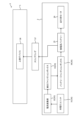
- FIG. 2 is a block diagram showing a schematic configuration of a high-power system.
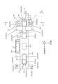
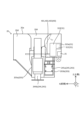
- FIG. 3 is a plan view of the main frame and components of the high-power system.
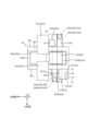
- FIG. 4 is an enlarged view corresponding to the portion X1 in FIG.
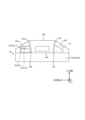
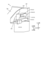
- FIG. 5 is a view taken along the line A1 in FIG.
- FIG. 6 is a view taken along the line A2 in FIG.
- FIG. 7 is a view taken along the line A3 in FIG.
- FIG. 8 is a view taken along the line A4 in FIG.
- FIG. 1 is a schematic diagram of a mobile crane 1 (a rough terrain crane in the illustrated case) according to this embodiment.
- the mobile crane include an all-terrain crane, a truck crane, and a loading truck crane (also called a cargo crane).
- the mobile crane 1 has a lower running body 2 and an upper rotating body 5.
- the mobile crane 1 is an electric crane equipped with a high-power battery 35 (see Figures 2 and 3).
- the mobile crane 1 runs on the power supplied from the high-power battery 35. In other words, the mobile crane 1 does not have an engine.
- the mobile crane 1 may also perform operations other than traveling (e.g., crane operation and/or heating) based on the power supplied from the high-voltage battery 35.
- Crane operation includes, for example, slewing operations and/or winch operations during cargo transport operations. The specific configuration of the mobile crane 1 will be described below.
- Figure 1 is a schematic diagram of a mobile crane 1.
- Figure 2 is a block diagram showing the schematic configuration of a high-power system 3 mounted on the mobile crane 1.
- the high-power system 3 is a system that uses a high-power battery 35 (described below) as its power source, and is a system that is composed of the high-power battery 35 and elements that are electrically connected to the high-power battery 35.
- Figure 2 shows the main elements that make up the high-power system 3.
- the high-power system 3 may also include elements other than the main elements shown in Figure 2.
- the upper rotating body 5 is provided on the upper part of the lower running body 2 and can rotate around the central axis of rotation ⁇ relative to the lower running body 2.
- the upper rotating body 5 has a rotating base 51, a telescopic boom 52, and a cab 53.
- the swivel base 51 is supported on the upper part of the lower running body 2 via bearings (not shown).
- the swivel base 51 rotates based on the power generated by a rotation actuator (not shown) provided on the upper rotating body 5.
- the rotation actuator is a hydraulic motor. This motor operates based on the supply and discharge of hydraulic oil.
- the hydraulic oil is supplied from the lower traveling body 2.
- the turning actuator may be an electric actuator (e.g., an electric motor). In this case, the turning actuator is driven by electricity supplied from the high-voltage battery 35 described below.
- the telescopic boom 52 is supported by a rotating base 51 and has multiple booms that are combined so that they can be extended and retracted.
- the telescopic boom 52 is raised and lowered based on the power generated by the raising and lowering actuator (specifically, the raising and lowering cylinder 54).
- the elevation cylinder 54 is a telescopic hydraulic cylinder that is provided on the upper rotating body 5.
- the elevation cylinder 54 operates based on the supply or discharge of hydraulic oil.
- the hydraulic oil is supplied from the lower traveling body 2.
- the elevation actuator may be an electric actuator (e.g., an electric motor). In this case, the elevation actuator is driven by power supplied from the high-power battery 35 described below.
- the telescopic boom 52 extends and retracts based on the power generated by the telescopic actuator (specifically, the telescopic cylinder 55).
- the telescopic cylinder 55 is a hydraulic cylinder and is provided inside the telescopic boom 52.
- the telescopic cylinder 55 operates based on the supply and discharge of hydraulic oil.
- the hydraulic oil is supplied from the lower traveling body 2.
- the telescopic actuator may be an electric actuator (e.g., an electric motor). In this case, the telescopic actuator is driven based on the power supplied from the high-voltage battery 35 described below.
- the telescopic boom 52 also supports a wire rope 56.
- the wire rope 56 hangs down from the tip of the telescopic boom 52 and has a hook 57 attached to its tip. A portion of the wire rope 56 is wound around a winch 58.
- the winch 58 is driven based on the power generated by a winch actuator (not shown).
- the winch actuator is provided on the rotating base 51 and is a hydraulic motor. This motor operates based on the supply or discharge of hydraulic oil.
- the hydraulic oil is supplied from the lower traveling body 2.
- the winch actuator may be an electric actuator (e.g., an electric motor). In this case, the winch actuator is driven by electricity supplied from the high-voltage battery 35 described below.
- the motor for the winch may be an electric motor.
- the electric motor for the winch is driven by power supplied from the high-voltage battery 35 described below.
- the X direction corresponds to the front-to-rear direction of the lower traveling body 2.
- the positive side of the X direction corresponds to the front side of the lower traveling body 2.
- the negative side of the X direction corresponds to the rear side of the lower traveling body 2.
- the Y direction corresponds to the left-to-right direction of the lower traveling body 2 and the vehicle width direction of the mobile crane 1.
- the positive side of the Y direction corresponds to the left side when looking forward from the lower traveling body 2.
- the negative side of the Y direction corresponds to the right side when looking forward from the lower traveling body 2.
- the Z direction corresponds to the up-down direction of the lower traveling body 2.
- the positive side of the Z direction corresponds to the upper side of the lower traveling body 2.
- the negative side of the Z direction corresponds to the lower side of the lower traveling body 2.
- the lower running body 2 can run on electricity. Specifically, the lower running body 2 has a main frame 20, a body 21, front tires 22, rear tires 23, and outriggers 24.
- the main frame 20 is a box-shaped member with a rectangular cross-sectional shape extending in the front-rear direction, and forms the skeleton of the lower running body 2.
- the main frame 20 has an upper plate portion 20a, a lower plate portion 20b, a right side plate portion 20c, a left side plate portion 20d, a front side plate portion 20e, and a rear side plate portion 20f.
- the main frame 20 also has a front battery storage space 201a and a rear battery storage space 201b that are formed by through holes that pass through the main frame 20 in the vertical direction.
- the front battery storage space 201a is provided in the main frame 20 between the center and the front end in the fore-and-aft direction.
- the rear battery storage space 201b is provided between the center and rear end of the main frame 20 in the front-rear direction.
- the cross-sectional shape of the portion of the main frame 20 where the front battery storage space 201a and the rear battery storage space 201b are formed is a closed cross section formed by multiple continuous plate portions. Note that the cross section of the main frame 20 refers to the cross section when the main frame 20 is cut in the YZ plane.
- the main frame 20 also has a slip ring arrangement space 201c in the center in the front-to-rear direction, which is formed by a through hole that passes through the main frame 20 in the up-down direction.
- the main frame 20 has a front outrigger support portion 202 at its front end.
- the front outrigger support portion 202 has a left outrigger support portion 202a and a right outrigger support portion 202b.
- the left outrigger support portion 202a and the right outrigger support portion 202b are each cylindrical and extend in the left-right direction.
- the left outrigger support portion 202a and the right outrigger support portion 202b are offset from each other in the front-to-rear direction and are adjacent to each other in the front-to-rear direction.
- the left outrigger support portion 202a is located forward of the right outrigger support portion 202b.
- the main frame 20 has a rear outrigger support portion 203 at its rear end.
- the rear outrigger support portion 203 has a left outrigger support portion 203a and a right outrigger support portion 203b.
- the left outrigger support portion 203a supports the left outrigger 244 of the rear outrigger 243 described below.
- the left outrigger support portion 203a is cylindrical and extends in the left-right direction.
- the right end portion of the left outrigger support portion 203a protrudes to the right beyond the right side plate portion 20c of the main frame 20.
- the left end portion of the left outrigger support portion 203a protrudes to the left beyond the left side plate portion 20d of the main frame 20.
- the right side outrigger support portion 203b supports the right side outrigger 245 of the rear outrigger 243 described below.
- the right side outrigger support portion 203b is cylindrical and extends in the left-right direction.
- the right end portion of the right side outrigger support portion 203b protrudes to the right beyond the right side plate portion 20c of the main frame 20.
- the left end portion of the right side outrigger support portion 203b protrudes to the left beyond the left side plate portion 20d of the main frame 20.
- the left outrigger support part 203a and the right outrigger support part 203b are arranged in a state where they are offset from each other in the fore-aft direction, but adjacent to each other in the fore-aft direction.
- the left outrigger support part 203a is located forward of the right outrigger support part 203b.
- the main frame 20 has a pair of support frames 204, 205 at the rear end.
- the support frame 204 is an example of a front support frame, and is a member for supporting the left outrigger support portion 203a on the main frame 20.
- the support frame 204 extends leftward from the left side plate portion 20d of the main frame 20.
- the support frame 204 is provided above the left end portion of the left outrigger support portion 203a in the rear outrigger support portion 203.
- the support frame 204 is disposed above the left end portion (base end portion) of the rear right outrigger 245 described below, and in front of the space to the left of the left side plate portion 20d of the main frame 20.
- the power supply unit 30 described below is provided in this space.
- the right end of the support frame 204 is connected to the upper end of the left side plate portion 20d.
- the left end of the support frame 204 is connected to the left end of the left outrigger support portion 203a. As shown in Figure 5, the support frame 204 is inclined so that the left end is positioned lower than the right end.
- the front and rear sides of the right end (base end) of the support frame 204 are curved. This configuration helps prevent stress concentration from occurring at the right end (base end) of the support frame 204.
- a tunnel-shaped space 206 (see FIG. 5) that opens in the front-rear direction.
- the space 206 is defined by the lower surface of the support frame 204 and the upper surface of the left outrigger support part 203a.
- a cable 40 that connects the normal charging port 311 (described below) to the current conversion part 32, and a cable 41 that connects the quick charging port 312 to the integrated junction box 33 are arranged.
- the support frame 205 is an example of a rear support frame, and is a member for supporting the right side outrigger support portion 203b on the main frame 20.
- the support frame 205 extends to the right from the right side plate portion 20c of the main frame 20.
- the support frame 205 is provided above the right end portion of the right side outrigger support portion 203b in the rear outrigger support portion 203.
- the support frame 205 is disposed above the right end portion (base end portion) of the rear left side outrigger 244 described below and at the rear of the space to the right of the right side plate portion 20c of the main frame 20.
- the current conversion unit 32 described below is provided in this space.
- the left end of the support frame 205 is connected to the upper end of the right side plate portion 20c.
- the right end of the support frame 205 is connected to the right end of the right outrigger support portion 203b. As shown in FIG. 5, the support frame 205 is inclined so that the right end is positioned lower than the left end.
- the front and rear sides of the left end (base end) of the support frame 205 are curved. This configuration helps prevent stress concentration from occurring at the left end (base end) of the support frame 205.
- the space 207 is defined by the lower surface of the support frame 205 and the upper surface of the right outrigger support part 203b. The front and rear ends of the space 207 are open.
- the main frame 20 also has a side support portion 208 in the center in the front-rear direction.
- the side support portion 208 is fixed to the right side plate portion 20c of the main frame 20.
- the side support portion 208 supports the integrated junction box 33, which will be described later.
- the body 21 (see Figure 1) is a member that constitutes the outer shape of the lower running body 2 and is supported by the main frame 20.
- the front tires 22 are rotatably supported at both ends of the front axle (not shown).
- the rear tires 23 are rotatably supported at both ends of the rear axle (not shown).
- the outriggers 24 have a front outrigger 240 and a rear outrigger 243.
- the front outrigger 240 has a left outrigger 241 and a right outrigger 242.
- the left outrigger 241 is supported by the left outrigger support portion 202a of the front outrigger support portion 202.
- the right outrigger 242 is supported by the right outrigger support portion 202b of the front outrigger support portion 202.
- the rear outrigger 243 is provided at the rear of the main frame 20.
- the rear outrigger 243 has a left outrigger 244 and a right outrigger 245 that are offset from each other in the front and rear.
- the left side outrigger 244 is an example of a first outrigger, and is supported by the left side outrigger support portion 203a of the rear outrigger support portion 203.
- the left side outrigger 244 is an outrigger that extends to the left side when in use.
- the left side outrigger 244 has a horizontal outrigger 244a and a vertical outrigger 244b.
- the side outrigger 244a extends in the left-right direction and is inserted into the left outrigger support portion 203a of the rear outrigger support portion 203.
- the side outrigger 244a can move in the left-right direction.
- the left outrigger support portion 203a is supported by the support frame 204. Therefore, the lateral outrigger 244a can also be considered to be supported by the support frame 204.
- the vertical outrigger 244b is fixed to the left end of the horizontal outrigger 244a.
- the vertical outrigger 244b can move (extend and retract) in the up and down direction.
- the right side outrigger 245 is an example of a second outrigger, and is supported by the right side outrigger support portion 203b of the rear outrigger support portion 203.
- the right side outrigger 245 is an outrigger that extends to the right when in use.
- the right side outrigger 245 is located further rearward than the left side outrigger 244.
- the right outrigger 245 has a horizontal outrigger 245a and a vertical outrigger 245b.
- the horizontal outrigger 245a extends in the left-right direction and is inserted into the right outrigger support portion 203b of the rear outrigger support portion 203.
- the lateral outrigger 245a can move left and right. As mentioned above, the right side outrigger support part 203b is supported by the support frame 205. Therefore, the lateral outrigger 245a can also be considered to be supported by the support frame 205.
- the vertical outrigger 245b is fixed to the right end of the horizontal outrigger 245a.
- the vertical outrigger 245b can move (extend and retract) in the up and down direction.
- the mobile crane 1 of this embodiment also has a high-power system 3.
- the high-power system 3 is a system for running the lower traveling body 2 and performing operations other than running of the mobile crane 1 (e.g., crane work and/or heating) based on power supplied from a high-power battery 35 described below.
- the configuration of the high-power system 3 will be described below.
- the mobile crane 1 of this embodiment also has a low-voltage system.
- the low-voltage system is a system for causing the mobile crane 1 to execute a predetermined process based on power supplied from a low-voltage battery (not shown) that has a lower voltage than the high-voltage battery 35.
- the low-voltage system is also a system for transmitting control signals for causing the mobile crane 1 to execute a predetermined process.
- the main elements of the high-power system 3 are a power supply unit 30, a traction motor 36, a slip ring 37, and an upper device 38.
- the power supply unit 30 is a unit for charging the high-power battery 35.
- the power supply unit 30 has a charging port unit 31, a current conversion unit 32, and a high-power battery 35.
- the power supply unit 30 also has an integrated junction box 33 and a battery junction box 34.
- the charging port unit 31 is provided at the rear end of the main frame 20. Specifically, the charging port unit 31 is disposed in the space above the rear outrigger 243 of the lower traveling body 2 and to the side of the main frame 20. More specifically, the charging port unit 31 is disposed in the space above the left end (base end) of the rear right outrigger 245 and to the left of the left side plate portion 20d of the main frame 20.
- the right outrigger 242 of the rear outrigger 243 is provided rearward of the left outrigger 241 of the rear outrigger 243.
- the configuration of the rear outrigger is not limited to the configuration of the rear outrigger 243 of this embodiment.
- the right outrigger of the rear outrigger may be provided forward of the left outrigger of the rear outrigger.
- the charging port unit may be disposed in a space above the right end (base end) of the rear left outrigger and to the right of the right side plate portion 20c of the main frame 20.
- the current conversion unit 32 is disposed in a space above the left end (base end) of the rear right outrigger 242 and to the left of the left side plate portion 20d of the main frame 20.
- the charging port unit 31 is disposed in the space above the portion of the rear right outrigger support portion 203b that is to the left of the left side plate portion 20d of the main frame 20 (the left end portion of the rear right outrigger support portion 203b). This space is also the space that exists behind the support frame 204.
- the charging port unit 31 has a housing 310, a normal charging port 311, and a quick charging port 312.
- the housing 310 is box-shaped and has a storage section.
- the housing 310 is supported by the main frame 20 via a support (not shown).
- the housing 310 has an openable and closable lid 310a on the rear side. An operator can access the storage section by opening the lid 310a.
- the shape of the housing is not limited to the shape of the housing 310 in this embodiment.
- Lights 25 are provided on the main frame 20 behind the rear end of the charging port unit 31 or below the bottom end of the charging port unit 31. This configuration helps prevent damage to the charging port unit 31.
- the lights 25 are, for example, brake lights or turn signal lights.
- the bottom end of the charging port unit 31 (normal charging port 311 and quick charging port 312) is located above the top end of the lights 25.
- the rear end of the charging port unit 31 (normal charging port 311 and quick charging port 312) is located forward of the rear end of the lights 25.
- Normal charging port 311 and quick charging port 312 are examples of charging ports, and are provided in the storage section of housing 310.
- Normal charging port 311 is a charging port for normal charging. When performing normal charging, the worker opens lid 310a and connects the charging equipment's plug for normal charging to normal charging port 311.
- Quick charge port 312 is a charging port for quick charging. When performing quick charging, the worker opens cover 310a and connects the quick charging plug of the charging equipment to quick charge port 312.
- the normal charging port 311 is connected to the current conversion unit 32, which will be described later, via a cable 40 (see Figures 3 and 4).
- the quick charging port 312 is connected to the integrated junction box 33, which will be described later, via a cable 41 (see Figures 3 and 4). In other words, the quick charging port 312 is not connected to the current conversion unit 32.
- the upper end of the charging port unit 31 (housing 310) is located below the upper surface of the main frame 20 (i.e., upper plate portion 20a).
- the rear end of the charging port unit 31 (housing 310) is located forward of the rear surface of the main frame 20 (i.e., rear plate portion 20f).
- the upper ends of the normal charging port 311 and the quick charging port 312 are located below the upper surface of the main frame 20 (i.e., upper plate portion 20a).
- the rear ends of the normal charging port 311 and the quick charging port 312 are located forward of the rear surface of the main frame 20 (i.e., rear plate portion 20f).
- the charging port unit 31 also has various indicators (not shown).
- the indicators include, for example, an indicator that shows the charging state of the high-power battery 35. Such indicators are also arranged in the storage section of the housing 310.
- the normal charging port 311 and the rapid charging port 312 face backward.
- facing backward means that the normals ⁇ 1 , ⁇ 2 of the rear end surfaces of the normal charging port 311 and the rapid charging port 312 include a backward component (a component on the negative side of the X direction).
- the normal charging port 311 and the rapid charging port 312 are oriented such that the normals ⁇ 1 , ⁇ 2 are parallel to the front-to-rear direction (in other words, only the backward component).
- the normal charging port 311 and the rapid charging port 312 may be arranged such that the normals ⁇ 1 , ⁇ 2 face, for example, diagonally backward to the left.
- the current conversion unit 32 is configured by an on-board charger and is provided in the space above the left outrigger 244 on the lower traveling body 2 and to the side of the main frame 20. Specifically, the current conversion unit 32 is disposed in the space above the right end (base end) of the rear left outrigger 244 and to the right of the right side plate portion 20c of the main frame 20.
- the current conversion unit 32 is disposed in the space above the portion of the rear left outrigger support part 203a that is to the right of the right side plate part 20c of the main frame 20 (the right end part of the rear left outrigger support part 203a).
- This space is also the space that exists between the support frame 205 and the tire fender 230 of the right rear tire 23 in the front-rear direction.
- the tire fender 230 is an example of a rear wheel fender.
- the current converter 32 converts the AC current supplied from the charging port unit 31 into DC current. The current converter 32 then sends the DC current to the high-power battery 35.
- the input terminal (not shown) of the current converter 32 is connected to the normal charging port 311 via a cable 40.
- the output terminal (not shown) of the current converter 32 is connected to the input terminal (not shown) of the integrated junction box 33 (described below) via a cable (not shown).
- the current converter 32 sends DC current to the high-power battery 35 via the integrated junction box 33.
- the current conversion unit 32 has a plurality of current conversion devices. Specifically, the current conversion unit 32 has a first current conversion device 321, a second current conversion device 322, and a third current conversion device 323. Note that the number of current conversion devices is not limited to the number of current conversion devices in this embodiment.
- the first current converter 321, the second current converter 322, and the third current converter 323 are offset in the front-to-rear direction and stacked vertically as shown in FIG. 7.
- the rear end face and the front end face of the first current converter 321 arranged in the upper tier are located forward of the rear end face and the front end face of the second current converter 322 and the third current converter 323.
- the rear end face and the front end face of the second current converter 322 arranged in the middle tier are located forward of the rear end face and the front end face of the third current converter 323.
- the first current converter 321, the second current converter 322, and the third current converter 323 are arranged to conform to the shape (curved shape) of the front side of the support frame 205, as shown in FIG. 7.
- the input terminals (not shown) of the first current converter 321, the second current converter 322, and the third current converter 323 are connected to the output terminal (not shown) of the normal charging port 311 via the first cable 401, the second cable 402, and the third cable 403.
- the first cable 401, the second cable 402, and the third cable 403 constitute the cable 40 described above.
- the electrical path (cable 40) that connects the normal charging port 311 and the current conversion unit 32 branches into three electrical paths (the first cable 401, the second cable 402, and the third cable 403) inside the housing 310.
- the first cable 401, the second cable 402, and the third cable 403 are arranged to extend downward from the first cable 401, the second cable 402, and the third cable 403 and pass under the main frame 20.
- the output terminals (not shown) of the current conversion unit 32 (first current conversion device 321, second current conversion device 322, and third current conversion device 323) are connected to the input terminals of the integrated junction box 33 described below via cables (not shown).
- the integrated junction box 33 is a device that distributes and supplies the power (DC current) supplied from the charging port unit 31 to the high-power battery 35.
- the integrated junction box 33 is supported by the side support portion 208 of the main frame 20.
- the input terminal (not shown) for normal charging of the integrated junction box 33 is connected to the output terminal of the current converter 32 via a cable (not shown). Also, the input terminal (not shown) for rapid charging of the integrated junction box 33 is connected to the output terminal (not shown) of the rapid charging port 312 via a cable 41 (see Figures 3 and 4).
- the output terminal (not shown) of the integrated junction box 33 is connected to the input terminal (not shown) of the battery junction box 34 via a cable (not shown).
- the battery junction box 34 is a device that distributes the power supplied from the integrated junction box 33 to the high-power battery 35.
- the battery junction box 34 has a front junction box 341, a first rear junction box 342, and a second rear junction box 343.
- the front junction box 341 is located above the front battery storage space 201a. In other words, the front junction box 341 is located outside the main frame 20.
- the input terminal (not shown) of the front junction box 341 is connected to the output terminal (not shown) of the integrated junction box 33 via a cable (not shown).
- the output terminal (not shown) of the front junction box 341 is connected to the input terminal (not shown) of the front battery 352 (first front battery 352a and second front battery 352b) described below via a cable (not shown).
- the first rear junction box 342 is located at the front end of the rear battery storage space 201b. In other words, the first rear junction box 342 is located inside the main frame 20.
- the upper surface of the first rear junction box 342 is located below the upper surface of the main frame 20 (i.e., the upper plate portion 20a).
- the input terminal (not shown) of the first rear junction box 342 is connected to the output terminal (not shown) of the integrated junction box 33 via a cable (not shown).
- the output terminal (not shown) of the first rear junction box 342 is connected via a cable (not shown) to the input terminal (not shown) of the rear internal battery 350 (first rear internal battery 350a and second rear internal battery 350b) described below.
- the second rear junction box 343 is disposed at the rear end of the rear battery storage space 201b.
- the lower half of the second rear junction box 343 is disposed inside the main frame 20.
- the upper half of the second rear junction box 343 is located above the upper surface of the main frame 20 (i.e., the upper plate portion 20a).
- the second rear junction box 343 is disposed rearward of the first rear junction box 342.
- the input terminal (not shown) of the second rear junction box 343 is connected to the output terminal (not shown) of the integrated junction box 33 via a cable (not shown).
- the output terminal of the second rear junction box 343 is connected to the input terminal (not shown) of the rear external battery 351 (first rear external battery 351a and second rear external battery 351b) described below via a cable (not shown).
- the high-power battery 35 is an example of a rechargeable battery, and supplies power to the electric devices that make up the mobile crane 1.
- the high-power system battery 35 is composed of multiple batteries. Specifically, the high-power system battery 35 has a rear internal battery 350, a rear external battery 351, and a front battery 352.
- the rear internal battery 350 has a first rear internal battery 350a and a second rear internal battery 350b.
- the first rear internal battery 350a and the second rear internal battery 350b are arranged in the rear battery storage space 201b. In other words, the first rear internal battery 350a and the second rear internal battery 350b are arranged inside the main frame 20.
- the upper end faces of the first rear internal battery 350a and the second rear internal battery 350b are located below the upper side surface of the main frame 20 (i.e., the upper plate portion 20a).
- the first rear internal battery 350a and the second rear internal battery 350b are arranged side by side in the front-to-rear direction.
- the first rear internal battery 350a and the second rear internal battery 350b are fixed to the main frame 20 via a fixing device such as a bracket (not shown).
- the input terminals (not shown) of the first rear internal battery 350a and the second rear internal battery 350b are connected to the output terminals (not shown) of the first rear junction box 342 via cables (not shown).
- the output terminals (not shown) of the first rear internal battery 350a and the second rear internal battery 350b are connected to the input terminal (not shown) of the driving motor 36.
- a junction box and/or an inverter may be provided between the first rear internal battery 350a and the second rear internal battery 350b and the driving motor 36.
- the dead space of the main frame 20 can be effectively utilized, allowing the rear internal battery 350 to be arranged compactly and preventing the rear internal battery 350 from being damaged by impact, etc.
- the rear external battery 351 has a first rear external battery 351a and a second rear external battery 351b.
- the first rear external battery 351a and the second rear external battery 351b are disposed above the rear battery storage space 201b.
- the first rear external battery 351a and the second rear external battery 351b are disposed above the upper surface of the main frame 20 (i.e., the upper plate portion 20a).
- first rear external battery 351a and the second rear external battery 351b are disposed outside the main frame 20.
- the first rear external battery 351a and the second rear external battery 351b are disposed side by side on the left and right.
- the first rear external battery 351a and the second rear external battery 351b are fixed to the main frame 20 via a fixing device such as a bracket (not shown).
- the input terminals (not shown) of the first rear external battery 351a and the second rear external battery 351b are connected to the output terminals (not shown) of the second rear junction box 343 via cables (not shown).
- the output terminals (not shown) of the first rear external battery 351a and the second rear external battery 351b are connected to the input terminal (not shown) of the driving motor 36 via a cable (not shown).
- a junction box and/or an inverter may be provided between the first rear external battery 351a, the second rear external battery 351b, and the driving motor 36.
- the front battery 352 includes a first front battery 352a and a second front battery 352b.
- the first front battery 352a and the second front battery 352b are arranged in the front battery storage space 201a. In other words, the first front battery 352a and the second front battery 352b are arranged inside the main frame 20.
- the upper end faces of the first front battery 352a and the second front battery 352b are located below the upper side surface of the main frame 20 (i.e., the upper plate portion 20a).
- the first front battery 352a and the second front battery 352b are arranged side by side in the front-to-rear direction.
- the first front battery 352a and the second front battery 352b are fixed to the main frame 20 via a fixing device such as a bracket (not shown).
- the input terminals (not shown) of the first front battery 352a and the second front battery 352b are connected to the output terminals (not shown) of the front junction box 341 via cables (not shown).
- the output terminals (not shown) of the first front battery 352a and the second front battery 352b are connected to the input terminal (not shown) of the driving motor 36 via a cable (not shown).
- a junction box and/or an inverter may be provided between the first front battery 352a and the second front battery 352b and the driving motor 36.
- the dead space of the main frame 20 can be effectively utilized, allowing the front battery 352 to be arranged compactly and preventing the front battery 352 from being damaged by impact, etc.
- the operator opens the cover 310a of the charging port unit 31 and connects the charging equipment's normal charging plug to the normal charging port 311.
- AC current is supplied from the charging equipment to the normal charging port 311.
- the AC current is sent from the normal charging port 311 via the cable 40 to the current converter 32.
- the current converter 32 the AC current is converted to DC current.
- the DC current is then sent to the high-voltage battery 35 via the integrated junction box 33 and the battery junction box 34.
- the worker opens the cover 310a of the charging port unit 31 and connects the charging equipment's normal charging plug to the rapid charging port 312.
- the DC current is then sent from the integrated junction box 33 via the battery junction box 34 to the high-voltage battery 35.
- the driving motor 36 is driven by the power supplied from the high-voltage battery 35 under the control of a control unit (not shown).
- the control unit adjusts the torque of the driving motor 36.
- the slip ring 37 is connected to the high-power battery 35 via a cable (not shown).
- the slip ring 37 is a device for transmitting power supplied from the high-power battery 35 from the lower traveling body 2 to the upper device 38 (see Figure 2) of the upper rotating body 5.
- the slip ring 37 also transmits the current and control signals flowing through the low-voltage system from the lower traveling body 2 to the upper device 38 of the upper rotating body 5.
- the upper device 38 is provided on the upper rotating body 5, and is a device that operates based on the power of the high-power battery 35.
- the actuator for rotation is an electric motor
- the electric motor for rotation is an example of an upper device.
- the actuator for winch is an electric motor
- the electric motor for winch is an example of an upper device.
- the slip ring 37 is connected to the electric motor for rotation and the electric motor for winch via an upper junction box (not shown).
- Such an upper junction box has the function of allocating the power of the high-power battery 35 supplied via the slip ring 37 to the electric motor for rotation and the electric motor for winch.
- the electric motor for rotation When power is supplied from the high-power battery 35, the electric motor for rotation is driven based on that power. The electric motor for rotation then rotates the upper rotating body 5.
- the electric motor for the winch When power is supplied from the high-voltage battery 35, the electric motor for the winch is driven by that power. The electric motor for the winch then rotates the winch (not shown). As a result, the wire rope 56 is wound up or unwound, and the hook 57 is raised or lowered.
- the efficiency of charging work can be improved.
- the telescopic boom 52 interferes with the charging equipment, so the mobile crane 1 cannot be parked facing forward in the parking space of the charging equipment.
- the mobile crane 1 is parked backwards in the parking space of the charging equipment.
- the normal charging port 311 and the quick charging port 312 are provided facing backwards at the rear end of the mobile crane 1, so that the worker can efficiently perform charging work with the mobile crane 1 parked backwards in the parking space of the charging equipment.
- an operator may perform charging operations while the mobile crane 1 is in an operating state.
- the operating state refers to a state in which the front outrigger 240 and the rear outrigger 243 are extended.
- the normal charging port 311 and the rapid charging port 312 are provided at the rear end of the mobile crane 1 facing rearward. Therefore, when an operator connects the charging plug of the charging equipment to the normal charging port 311 or the rapid charging port 312, the rear outrigger 243 does not get in the way. As a result, this embodiment can improve the efficiency of charging operations while the mobile crane 1 is in an operating state.
- the charging port unit 31 is provided near the left end of the rear side of the main frame 20, so that when the mobile crane 1 is parked in the charging facility for parallel parking, the charging port unit 31 can be positioned near the charging facility.
- the charging port unit 31 and the current conversion unit 32 are disposed in the space above the rear outrigger 243 and to the side of the main frame 20. This space is restricted by the shapes of the support frames 204, 205, the rear outrigger 243, the lights 25, and the tire fender 230 of the rear tire 23, etc.
- the charging port unit 31 and current conversion unit 32 which have an innovative configuration, are placed in a space that is subject to these various constraints. In this way, this embodiment makes it possible to effectively use the space in the mobile crane 1.
- the first current converter 321, second current converter 322, and third current converter 323 constituting the current converter 32 are arranged in a state where they are offset in the front-to-rear direction and stacked one on top of the other.
- a relatively large space can be secured between the front side surface of the support frame 205 and the current converter 32, for example, to route cables, etc.
- This configuration contributes to improving the freedom of design.
- Other actions and effects achieved by the mobile crane 1 according to this embodiment are as described above.
- the crane according to the present invention is not limited to a rough terrain crane, but may be any type of mobile crane, such as an all-terrain crane, a truck crane, or a loaded truck crane (also called a cargo crane).
Landscapes
- Engineering & Computer Science (AREA)
- Mechanical Engineering (AREA)
- Power Engineering (AREA)
- Transportation (AREA)
- Life Sciences & Earth Sciences (AREA)
- Sustainable Development (AREA)
- Sustainable Energy (AREA)
- Automation & Control Theory (AREA)
- Electric Propulsion And Braking For Vehicles (AREA)
- Jib Cranes (AREA)
Abstract
Description
ブームを支持する旋回体を有するクレーンであって、
旋回体を支持するメインフレームを有し、電力により走行する走行車体と、
メインフレームの後部に前後にずれて設けられた左側アウトリガ支持部及び右側アウトリガ支持部と、
走行車体に電力を供給する充電式バッテリーを有する給電ユニットと、を備え、
給電ユニットは、走行車体における左側アウトリガ支持部の上方且つメインフレームの右側の空間に、充電口から供給された交流電流を直流電流に変換し充電式バッテリーに送る電流変換部を有する。
図1は、本実施形態に係る移動式クレーン1(図示の場合、ラフテレーンクレーン)の模式図である。移動式クレーンとして、オールテレーンクレーン、トラッククレーン、又は積載形トラッククレーン(カーゴクレーンともいう。)等が挙げられる。
以上のような構成を有する本実施形態によれば、強電系バッテリー35の電力に基づいて走行可能な移動式クレーン1を実現できる。
2 下部走行車体
20 メインフレーム
20a 上側板部
20b 下側板部
20c 右側板部
20d 左側板部
20e 前側板部
20f 後側板部
201a 前側バッテリー収容空間
201b 後側バッテリー収容空間
201c スリップリング配置空間
202 前側アウトリガ支持部
202a 左側アウトリガ支持部
202b 右側アウトリガ支持部
203 後側アウトリガ支持部
203a 左側アウトリガ支持部
203b 右側アウトリガ支持部
204、205 サポートフレーム
206、207 空間
208 側方支持部
21 ボディ
22 前側タイヤ
23 後側タイヤ
230 タイヤフェンダー
24 アウトリガ
240 前側アウトリガ
241 左側アウトリガ
242 右側アウトリガ
243 後側アウトリガ
244 左側アウトリガ
244a 横アウトリガ
244b 縦アウトリガ
245 右側アウトリガ
245a 横アウトリガ
245b 縦アウトリガ
25 灯火類
3 強電系システム
30 給電ユニット
31 充電口ユニット
310 ハウジング
310a 蓋
311 普通充電口
312 急速充電口
32 電流変換部
321 第一電流変換装置
322 第二電流変換装置
323 第三電流変換装置
33 統合ジャンクションボックス
34 バッテリージャンクションボックス
341 前側ジャンクションボックス
342 第一後側ジャンクションボックス
343 第二後側ジャンクションボックス
35 強電系バッテリー
350 後側内部バッテリー
350a 第一後側内部バッテリー
350b 第二後側内部バッテリー
351 後側外部バッテリー
351a 第一後側外部バッテリー
351b 第二後側外部バッテリー
352 前側バッテリー
352a 第一前側バッテリー
352b 第二前側バッテリー
36 走行用モータ
37 スリップリング
38 上部デバイス
40 ケーブル
401 第一ケーブル
402 第二ケーブル
403 第三ケーブル
41 ケーブル
5 上部旋回体
51 旋回台
52 伸縮式ブーム
53 キャブ
54 起伏用シリンダ
55 伸縮用シリンダ
56 ワイヤロープ
57 フック
58 ウインチ
Claims (5)
- ブームを支持する旋回体を有するクレーンであって、
前記旋回体を支持するメインフレームを有し、電力により走行する走行車体と、
前記メインフレームの後部に前後にずれて設けられた左側アウトリガ支持部及び右側アウトリガ支持部と、
前記走行車体に前記電力を供給する充電式バッテリーを有する給電ユニットと、を備え、
前記給電ユニットは、前記走行車体における前記左側アウトリガ支持部の上方且つ前記メインフレームの右側の空間に、充電口から供給された交流電流を直流電流に変換し前記充電式バッテリーに送る電流変換部を有する、
クレーン。 - 前記メインフレームは、前記空間の後方に、前記メインフレームから側方に延在し、前記右側アウトリガ支持部を支持する後側サポートフレームを有し、
前記電流変換部は、前記後側サポートフレームの前方、且つ、前記走行車体の後輪フェンダーの後方、且つ、前記メインフレームの上面よりも下方に配置されている、請求項1に記載のクレーン。 - 前記メインフレームは、前記空間の後方に、前記メインフレームから側方に延在し、前記右側アウトリガ支持部を支持する後側サポートフレームを有し、
前記電流変換部は、前記後側サポートフレームの前方に、前後方向にオフセットされ、上下に積層されて配置された複数の電流変換装置を有する、
請求項1に記載のクレーン。 - 前記充電口は、前記走行車体における前記右側アウトリガ支持部の上方且つ前記メインフレームの側方の空間に配置されている、請求項1に記載のクレーン。
- 前記メインフレームの前後方向における中央部の側方に設けられ、前記充電口から供給された電力を、前記充電式バッテリーに分散して供給する統合ジャンクションボックスを備え、
前記電流変換部は、前後方向において、前記充電口と前記統合ジャンクションボックスとの間に配置されている、請求項4に記載のクレーン。
Priority Applications (2)
| Application Number | Priority Date | Filing Date | Title |
|---|---|---|---|
| US19/104,367 US20260054583A1 (en) | 2022-10-25 | 2023-09-06 | Crane |
| EP23882259.7A EP4610093A4 (en) | 2022-10-25 | 2023-09-06 | CRANE |
Applications Claiming Priority (2)
| Application Number | Priority Date | Filing Date | Title |
|---|---|---|---|
| JP2022170623A JP7521569B2 (ja) | 2022-10-25 | 2022-10-25 | クレーン |
| JP2022-170623 | 2022-10-25 |
Publications (1)
| Publication Number | Publication Date |
|---|---|
| WO2024090046A1 true WO2024090046A1 (ja) | 2024-05-02 |
Family
ID=90830419
Family Applications (1)
| Application Number | Title | Priority Date | Filing Date |
|---|---|---|---|
| PCT/JP2023/032466 Ceased WO2024090046A1 (ja) | 2022-10-25 | 2023-09-06 | クレーン |
Country Status (4)
| Country | Link |
|---|---|
| US (1) | US20260054583A1 (ja) |
| EP (1) | EP4610093A4 (ja) |
| JP (1) | JP7521569B2 (ja) |
| WO (1) | WO2024090046A1 (ja) |
Citations (6)
| Publication number | Priority date | Publication date | Assignee | Title |
|---|---|---|---|---|
| JP2002241080A (ja) * | 2001-02-16 | 2002-08-28 | Komatsu Ltd | 油圧パワーユニット搭載クレーン車 |
| JP2014151994A (ja) * | 2013-02-07 | 2014-08-25 | Tadano Ltd | ブーム式作業車における電動制御ユニットの設置構造 |
| US20180056902A1 (en) * | 2016-08-30 | 2018-03-01 | Illinois Tool Works Inc. | Methods and apparatus to power a crane on a work truck using an engine-powered service pack |
| JP2021046319A (ja) | 2019-09-20 | 2021-03-25 | 株式会社タダノ | 作業車両連携システムおよび高所作業車 |
| JP2022039774A (ja) * | 2020-08-28 | 2022-03-10 | 株式会社前田製作所 | 電動式の小型移動式クレーン |
| JP2022170623A (ja) | 2021-04-28 | 2022-11-10 | ベア ロボティクス インク | ロボットを利用してサービスを提供するための方法、システムおよび非一過性のコンピュータ読み取り可能記録媒体 |
Family Cites Families (4)
| Publication number | Priority date | Publication date | Assignee | Title |
|---|---|---|---|---|
| JP6202665B2 (ja) * | 2013-03-22 | 2017-09-27 | 株式会社タダノ | 作業機械の外部電源接続装置 |
| JP7366710B2 (ja) * | 2019-11-25 | 2023-10-23 | 株式会社加藤製作所 | 建設機械 |
| DE102021119538A1 (de) * | 2021-07-28 | 2023-02-02 | Liebherr-Werk Ehingen Gmbh | Energieversorgungssystem und -verfahren für ein Arbeitsgerät |
| DE102022127920A1 (de) * | 2022-10-21 | 2024-05-02 | Liebherr-Werk Biberach Gmbh | Elektrifizierte Bau- und/oder Materialumschlagsmaschine, insbesondere Kran |
-
2022
- 2022-10-25 JP JP2022170623A patent/JP7521569B2/ja active Active
-
2023
- 2023-09-06 EP EP23882259.7A patent/EP4610093A4/en active Pending
- 2023-09-06 US US19/104,367 patent/US20260054583A1/en active Pending
- 2023-09-06 WO PCT/JP2023/032466 patent/WO2024090046A1/ja not_active Ceased
Patent Citations (6)
| Publication number | Priority date | Publication date | Assignee | Title |
|---|---|---|---|---|
| JP2002241080A (ja) * | 2001-02-16 | 2002-08-28 | Komatsu Ltd | 油圧パワーユニット搭載クレーン車 |
| JP2014151994A (ja) * | 2013-02-07 | 2014-08-25 | Tadano Ltd | ブーム式作業車における電動制御ユニットの設置構造 |
| US20180056902A1 (en) * | 2016-08-30 | 2018-03-01 | Illinois Tool Works Inc. | Methods and apparatus to power a crane on a work truck using an engine-powered service pack |
| JP2021046319A (ja) | 2019-09-20 | 2021-03-25 | 株式会社タダノ | 作業車両連携システムおよび高所作業車 |
| JP2022039774A (ja) * | 2020-08-28 | 2022-03-10 | 株式会社前田製作所 | 電動式の小型移動式クレーン |
| JP2022170623A (ja) | 2021-04-28 | 2022-11-10 | ベア ロボティクス インク | ロボットを利用してサービスを提供するための方法、システムおよび非一過性のコンピュータ読み取り可能記録媒体 |
Non-Patent Citations (1)
| Title |
|---|
| See also references of EP4610093A4 |
Also Published As
| Publication number | Publication date |
|---|---|
| JP7521569B2 (ja) | 2024-07-24 |
| EP4610093A4 (en) | 2026-02-25 |
| JP2024062643A (ja) | 2024-05-10 |
| EP4610093A1 (en) | 2025-09-03 |
| US20260054583A1 (en) | 2026-02-26 |
Similar Documents
| Publication | Publication Date | Title |
|---|---|---|
| CN112188968B (zh) | 电动车辆 | |
| BR112021003979A2 (pt) | máquina elétrica de mineração para carregamento, transporte e descarte | |
| WO2023140371A1 (ja) | クレーン | |
| CN102714424B (zh) | 电力供给装置、起重机及电力供给方法 | |
| KR20130124534A (ko) | 전동식 작업 차량 및 그 배터리 유지 구조 | |
| JP7824750B2 (ja) | ダンプトラック | |
| CN114086625A (zh) | 电动挖掘机 | |
| WO2023112793A1 (ja) | 電動作業車 | |
| CN205873727U (zh) | 一种新能源起重机及其动力系统 | |
| JP7521569B2 (ja) | クレーン | |
| JP7480818B1 (ja) | クレーン | |
| IT202200026715A1 (it) | Dispositivo caricabatterie portatile per telehandler. | |
| JP6189010B2 (ja) | クレーン、及びクレーンの電力供給方法 | |
| JP7452579B2 (ja) | クレーン | |
| DE202016006966U1 (de) | Mobilkran | |
| JP7447939B2 (ja) | クレーン | |
| WO2024127773A1 (ja) | クレーン | |
| JP2024085555A (ja) | クレーン | |
| JP7211609B2 (ja) | 電源システム | |
| CN219215161U (zh) | 一种动力平台及上换电式矿用纯电宽体车 | |
| JP7468574B2 (ja) | クレーン | |
| CN118419160A (zh) | 车身压重模组、下车总成及工程机械 | |
| SE544962C2 (en) | An apparatus comprising an interface for providing an electrical connection between two vehicles | |
| KR20120051374A (ko) | 승객석에 붐대 및 붐 회동부를 설치한 견인차 | |
| WO2025062699A1 (ja) | ダンプトラック |
Legal Events
| Date | Code | Title | Description |
|---|---|---|---|
| 121 | Ep: the epo has been informed by wipo that ep was designated in this application |
Ref document number: 23882259 Country of ref document: EP Kind code of ref document: A1 |
|
| WWE | Wipo information: entry into national phase |
Ref document number: 2023882259 Country of ref document: EP |
|
| NENP | Non-entry into the national phase |
Ref country code: DE |
|
| ENP | Entry into the national phase |
Ref document number: 2023882259 Country of ref document: EP Effective date: 20250526 |
|
| WWP | Wipo information: published in national office |
Ref document number: 2023882259 Country of ref document: EP |