WO2024095612A1 - ガスシールドアーク溶接方法および溶接継手の製造方法 - Google Patents
ガスシールドアーク溶接方法および溶接継手の製造方法 Download PDFInfo
- Publication number
- WO2024095612A1 WO2024095612A1 PCT/JP2023/033083 JP2023033083W WO2024095612A1 WO 2024095612 A1 WO2024095612 A1 WO 2024095612A1 JP 2023033083 W JP2023033083 W JP 2023033083W WO 2024095612 A1 WO2024095612 A1 WO 2024095612A1
- Authority
- WO
- WIPO (PCT)
- Prior art keywords
- welding
- pulse
- less
- gas
- peak current
- Prior art date
- Legal status (The legal status is an assumption and is not a legal conclusion. Google has not performed a legal analysis and makes no representation as to the accuracy of the status listed.)
- Ceased
Links
Images



Classifications
-
- B—PERFORMING OPERATIONS; TRANSPORTING
- B23—MACHINE TOOLS; METAL-WORKING NOT OTHERWISE PROVIDED FOR
- B23K—SOLDERING OR UNSOLDERING; WELDING; CLADDING OR PLATING BY SOLDERING OR WELDING; CUTTING BY APPLYING HEAT LOCALLY, e.g. FLAME CUTTING; WORKING BY LASER BEAM
- B23K9/00—Arc welding or cutting
- B23K9/06—Arrangements or circuits for starting the arc, e.g. by generating ignition voltage, or for stabilising the arc
- B23K9/073—Stabilising the arc
-
- B—PERFORMING OPERATIONS; TRANSPORTING
- B23—MACHINE TOOLS; METAL-WORKING NOT OTHERWISE PROVIDED FOR
- B23K—SOLDERING OR UNSOLDERING; WELDING; CLADDING OR PLATING BY SOLDERING OR WELDING; CUTTING BY APPLYING HEAT LOCALLY, e.g. FLAME CUTTING; WORKING BY LASER BEAM
- B23K9/00—Arc welding or cutting
- B23K9/09—Arrangements or circuits for arc welding with pulsed current or voltage
-
- B—PERFORMING OPERATIONS; TRANSPORTING
- B23—MACHINE TOOLS; METAL-WORKING NOT OTHERWISE PROVIDED FOR
- B23K—SOLDERING OR UNSOLDERING; WELDING; CLADDING OR PLATING BY SOLDERING OR WELDING; CUTTING BY APPLYING HEAT LOCALLY, e.g. FLAME CUTTING; WORKING BY LASER BEAM
- B23K9/00—Arc welding or cutting
- B23K9/095—Monitoring or automatic control of welding parameters
-
- B—PERFORMING OPERATIONS; TRANSPORTING
- B23—MACHINE TOOLS; METAL-WORKING NOT OTHERWISE PROVIDED FOR
- B23K—SOLDERING OR UNSOLDERING; WELDING; CLADDING OR PLATING BY SOLDERING OR WELDING; CUTTING BY APPLYING HEAT LOCALLY, e.g. FLAME CUTTING; WORKING BY LASER BEAM
- B23K9/00—Arc welding or cutting
- B23K9/16—Arc welding or cutting making use of shielding gas
Definitions
- the present invention relates to a gas-shielded arc welding method and a method for manufacturing a welded joint that suppresses slag and produces a stable welded joint shape.
- components used in corrosive environments are subjected to anti-rust treatments such as chemical conversion coating and electrocoating after welding to ensure corrosion resistance.
- rust and corrosion may be observed at the weld and its vicinity.
- corrosion that occurs in components that have been electrocoated tends to start at the weld, and over time it spreads over a wide area at the weld and its surroundings, accompanied by blistering of the paint film, and also progresses in the thickness direction.
- the plate thickness at the weld and its vicinity decreases, resulting in a decrease in the strength of the weld and ultimately the strength of the component.
- a load acts on the weld (such as an automobile's suspension components)
- a chemical conversion treatment (such as zinc phosphate treatment) is applied to the base steel sheet and weld metal as a pretreatment to improve adhesion between the electrodeposition coating and the base steel sheet and weld metal, and then electrodeposition painting is performed.
- Zinc phosphate treatment a widely used example of a chemical conversion treatment, is a technique in which zinc phosphate crystals are grown on the surface of the base steel sheet and weld metal to improve the adhesion of the coating during electrodeposition painting.
- paint blistering frequently occurs over a wide area at and around the weld over time.
- the starting point of corrosion from the weld is (a) Slag adhering to the weld (mainly the surface of the weld bead), (b) Welding fumes adhering to the welded part; (c) Oxides formed on the surface of steel plates exposed to high temperatures by welding; has been known for some time. Even if a member having the above-mentioned deposits (a) and (b) or oxides (c) present in the welded portion is subjected to chemical conversion treatment, these deposits and products will cause localized areas that are not covered with a chemical conversion treatment layer made of zinc phosphate crystals to remain, starting from these deposits and products.
- Patent Document 1 discloses a technique in which after arc welding and before electrocoating, the weld and its vicinity are sprayed or immersed in a non-oxidizing acidic solution with a pH of 2 or less and a liquid temperature of 30 to 90°C. This technique removes the above-mentioned (a) slag, (b) welding fumes, and (c) oxides by dissolving the weld beads and steel plate in a non-oxidizing solution.
- Patent Document 2 discloses a technology that reduces the total Si content of the welding wire and base material used in arc welding, and increases the total Mn content of the welding wire and base material, thereby improving the corrosion resistance of the weld and its vicinity after painting.
- Patent Document 3 discloses a technology for forming a sufficient chemical conversion layer by adjusting the components of the treatment liquid used in the chemical conversion treatment, even in weld beads that contain slag, welding fumes, and oxides. Specifically, the formation of the chemical conversion layer is facilitated by performing surface treatment using a surface adjustment liquid containing zinc phosphate colloid. Furthermore, by performing chemical conversion treatment using a zinc phosphate treatment liquid with an F content of 100 mass ppm or more, slag, welding fumes, and oxides are dissolved and removed, improving the adhesion of the coating film formed by electrocoating.
- Patent Document 3 uses a zinc phosphate treatment liquid that contains fluorine, which is designated as a toxic substance, so when the waste liquid is discharged outside the factory, the fluorine content must be reduced to a level that meets environmental standards. Therefore, in addition to the parts manufacturing equipment, large-scale waste liquid treatment equipment is required.
- the present invention was made in consideration of these problems, and aims to provide a gas-shielded arc welding method and a method for manufacturing a welded joint that can prevent oxygen from being mixed into the weld metal and suppress the generation of slag without using special equipment, and can stably obtain a welded joint with a good bead shape.
- the inventors have discovered that the most effective way to improve the corrosion resistance of welds and stably obtain welded joints with good bead shapes is to reduce the amount of slag that adheres to the welds and to achieve periodic short-circuit transfer using pulse welding.
- the factor obtained by dividing the difference between the pulse peak current (Ip) and the pulse base current (Ib) by the distance between the base material and the contact tip (L) is found to be an index of the ease of short circuiting, and a technology has been found that by having the factor satisfy a predetermined relational expression with the welding speed (V) according to the welding speed, a welded joint with a good bead shape can be stably obtained.
- a gas-shielded arc welding method for joining a base metal by short-circuiting a welding wire supplied with power from a contact tip in a welding torch comprising:
- the gas shielded arc welding method is a pulse welding method in which a pulse peak current (Ip) and a pulse base current (Ib) are periodically repeated, and the pulse peak current (Ip) of the pulse welding is 300 A or more and 600 A or less,
- the welding speed (V) is 80 cm/min or more and 200 cm/min or less, When the welding speed (V) is 80 cm/min or more and less than 120 cm/min, the pulse peak current (Ip), the pulse base current (Ib), the distance (L) between the base metal and the contact tip, and the welding speed (V) satisfy the following formula (1): When the welding speed (V) is 120 cm/min or more and 200 cm/min or less, the pulse peak current (Ip), the pulse base current
- Ip (A) is the pulse peak current
- Ib (A) is the pulse base current
- L (mm) is the distance between the base material and the contact tip
- V (cm/min) is the welding speed.
- the present invention it is possible to stably obtain welded joints with good bead shapes over a wide range of welding speed conditions. Moreover, it is possible to suppress the intrusion of oxygen into the weld metal and the generation of slag without making special changes to the specifications of the welding equipment used in conventional carbon dioxide welding, MAG welding using a mixture of inert gas and active gas, or MIG welding using a gas mainly composed of inert gas.
- FIG. 1 is a schematic diagram showing an example of a welded joint produced by arc welding.
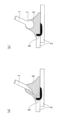
- 2(a) and 2(b) are schematic diagrams showing droplet transfer in conventional arc welding.
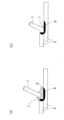
- 3(a) and 3(b) are schematic diagrams illustrating short-circuit transfer in accordance with the present invention.
- FIG. 2 is a schematic diagram showing a pulse current waveform in arc welding according to the present invention.
- FIG. 2 is a schematic diagram showing the bead area and slag coverage area of a weld bead.
- FIG. 4 is a schematic diagram showing minimum and maximum values of a bead width.
- FIG. 1 is a schematic diagram showing an example of a welded joint produced by arc welding, illustrating an embodiment of the present invention.
- fillet welding of a lap joint is shown as a representative example, but the present invention does not limit the shape of the welded joint and the welding position.
- the welding wire 1 which is continuously fed from the welding torch 2 through the center of the welding torch 2 to the base material 3 (more specifically, a weld line consisting of the corner of the step formed by stacking two layers of base material 3), is used as the anode, and the base material 3 is used as the cathode, and a welding voltage is applied from a welding power source (not shown).
- a contact tip 11 is attached to the welding torch 2, and the contact tip 11 plays the role of supplying power to the welding wire 1 and guiding the feed.
- An arc 5 is formed between the welding wire 1 and the base material 3 by ionizing and plasmatizing a part of the Ar shielding gas (not shown) supplied from the welding torch 2.
- the part of the Ar shielding gas that does not ionize and flows from the welding torch 2 to the base material 3 plays the role of insulating the arc 5 and the molten pool (not shown in FIG. 1) formed by melting the base material 3 from the outside air.
- the heat input from the arc 5 melts the tip of the welding wire 1 into a molten droplet, and the molten droplet is transported to the molten pool by electromagnetic force, gravity, etc. This phenomenon occurs continuously as the welding torch 2 or base material 3 moves, causing the molten pool to solidify behind the weld line, forming a weld bead 6. This achieves the joining of at least two steel plates.
- the cathode spot is not fixed in MIG welding, which does not generate oxides derived from O 2 or CO 2 , and the cathode spot moves around the surface of the base material vigorously in search of a place with a low work function. For this reason, the welding is unstable, and a welded joint with a meandering or wavy shape of the weld bead 6 is obtained.
- 2(a) and 2(b) are schematic diagrams illustrating droplet transfer in conventional MIG welding.
- the welding wire 1 melts and is continuously transported from a long and thin liquid column to the molten pool 8.
- the factor ((Ip-Ib)/L) obtained by dividing the difference between the pulse peak current (Ip) and the pulse base current (Ib) by the distance (L) between the contact tip and the base metal 3 indicates the ease of short-circuit transfer, and it has been found that it is preferable to set (Ip-Ib)/L in the range of 20 to 43, and further that when a predetermined relationship is satisfied for various welding speeds, meandering of the weld bead 6 can be suppressed.
- Ar gas of 98% by volume or more In order to improve the corrosion resistance of the welded portion, it is necessary to suppress the amount of slag produced at the welded portion, and for this purpose, it is important to suppress the oxidation of Si, Mn, Ti, etc. contained in the steel plate and the welding wire. For this reason, it is necessary to use a gas containing 98% by volume or more of Ar as a shielding gas. It is preferable to use 99% by volume or more of Ar. The upper limit is not limited, and Ar may be 100% by volume.
- Pulse peak current (Ip) is 300A or more and 600A or less
- FIG. 4 shows a schematic diagram of a pulse current waveform in the arc welding of the present invention.
- Pulse welding is a method in which a pulse peak current (Ip) and a pulse base current (Ib) are periodically repeated to perform welding. If the pulse peak current (Ip) is too small, the droplet 7 formed at the tip of the welding wire 1 cannot be pushed down to the molten pool 8, the short circuit becomes unstable, and sufficient heat input cannot be secured, which may cause deterioration of the bead shape. Therefore, the pulse peak current (Ip) is set to 300A or more.
- the pulse peak current (Ip) is preferably 350A or more, more preferably 380A or more, and even more preferably 400A or more.
- the pulse peak current (Ip) is set to 600A or less. It is preferably 590A or less, more preferably 580A or less, and even more preferably 570A or less. Since a short circuit occurs during the pulse peak current, the pulse peak current time (tp) per cycle is preferably 0.5 ms or more.
- the pulse peak current time (tp) per cycle is more preferably 0.7 ms or more, and even more preferably 0.8 ms or more. If the pulse peak current time (tp) per cycle is excessively large, the arc 5 and the molten pool 8 may become disturbed during a short circuit, resulting in poor weld bead shape, so the pulse peak current time (tp) per cycle is desirably 3.5 ms or less.
- the pulse peak current time (tp) per cycle is more preferably 3.3 ms or less, and even more preferably 3.2 ms or less.
- Pulse base current (Ib) is 30 A or more and 120 A or less (optimal condition) If the pulse base current (Ib) is too small, the arc discharge during the pulse base period becomes unstable, causing deterioration of the bead shape, and may result in insufficient penetration. For this reason, the pulse base current (Ib) is preferably 30 A or more.
- the pulse base current (Ib) is more preferably 35 A or more. Further, it is more preferably 40 A or more, and most preferably 45 A or more.
- the pulse base current (Ib) is preferably 120 A or less.
- the pulse base current (Ib) is more preferably 110 A or less. Further, it is more preferably 100 A or less, and most preferably 90 A or less.
- the pulse base current time (tb) per cycle (one pulse cycle) is preferably 1.0 ms or more.
- the pulse base current time (tb) per cycle (one pulse cycle) is more preferably 1.5 ms or more, and even more preferably 2.0 ms or more.
- the pulse base current time (tb) per cycle is preferably 10.0 ms or less.
- the pulse base current time (tb) per cycle is more preferably 9.0 ms or less, and even more preferably 8.0 ms or less.
- the rise time (tup) is 0.1 ms or more. More preferably, it is 0.3 ms or more, and even more preferably, it is 0.5 ms or more. It is preferable that the rise time (tup) is 3.0 ms or less. More preferably, it is 2.8 ms or less, and even more preferably, it is 2.5 ms or less. It is preferable that the fall time (tdown) is 0.1 ms or more.
- the fall time (tdown) is 3.0 ms or less. More preferably, it is 2.8 ms or less, and even more preferably, it is 2.5 ms or less.
- Welding speed (V) is 80 cm/min or more and 200 cm/min or less
- the welding speed (V) is high, the stability of the arc 5 decreases, making it difficult to control periodic short circuit transfer. The above phenomenon becomes particularly noticeable under welding conditions of 80 cm/min or more, and it becomes necessary to limit the welding speed to the contents described below.
- the welding speed (V) of the present invention is set to be 80 cm/min or more and 200 cm/min or less.
- the factor (Ip-Ib)/L which is the difference between the pulse peak current (Ip) and the pulse base current (Ib) divided by the distance (L) between the base material 3 and the contact tip 11, is not particularly limited, but has been found in the present invention as an index of the ease of short-circuit transfer, and is an important feature of the present invention. If (Ip-Ib)/L is too small, short-circuit transfer is unlikely to occur, and even if it does occur, stable short-circuit transfer is difficult, resulting in a poor bead shape. For this reason, (Ip-Ib)/L is preferably 20 A/mm or more. More preferably, it is 22 A/ms or more, and even more preferably, it is 25 A/ms or more.
- (Ip-Ib)/L is preferably 43 A/mm or less. More preferably, it is 41 A/ms or less, and even more preferably, it is 40 A/ms or less.
- the pulse peak current (Ip), the pulse base current (Ib), the distance (L) between the base material and the contact tip, and the welding speed (V) satisfy the formulas (1) and (2) below: 0.15V-3 ⁇ (Ip-Ib)/L ⁇ 0.1V+38 (when the welding speed V is 80 cm/min or more and less than 120 cm/min)... (1) 0.18V-5 ⁇ (Ip-Ib)/L ⁇ 0.12V+35 (when the welding speed V is 120 cm/min or more and 200 cm/min or less) ...
- Ip (A) is the pulse peak current
- Ib (A) is the pulse base current
- L (mm) is the distance between the base material and the contact tip
- V (cm/min) is the welding speed.
- the average frequency (short circuit frequency) F (Hz) of the short circuit transfer affects the volume of the droplet 7 at the wire end, and is not particularly limited, but is preferably 20 Hz or more. More preferably, it is 30 Hz or more, and even more preferably, it is 40 Hz or more. As an upper limit, it is preferably 200 Hz or less. More preferably, it is 180 Hz or less, and even more preferably, it is 150 Hz or less.
- the average frequency (short circuit frequency) F (Hz) of the short circuit transfer can be measured, for example, by monitoring the transition of the arc voltage during welding with an oscilloscope, counting the number of times it becomes zero, and dividing the count number by the monitoring time to obtain the number of counts per second.
- the monitoring time is too short, the variation in the count number will be large, so it is preferably 0.5 s or more. It is more preferable to set it to 0.8 s or more, and even more preferable to set it to 1.0 s or more.
- the upper limit is not particularly limited, but it is preferable to set it to 3.0 s or less because it takes a lot of time to count and workability will decrease if the volume of measurement data increases. For example, when measuring the short circuit frequency in-process and implementing feedback control of the welding conditions, if the monitoring time is too long, it becomes difficult to implement instantaneous feedback control according to the welding conditions.
- Preferable ranges of welding conditions include, for example, a welding current of 150A to 300A, an arc voltage of 20V to 35V, a distance between the base material 3 and the contact tip 11 of 5mm to 30mm, and an Ar shielding gas flow rate of 10L/min to 25L/min.
- the welding current is preferably 150A or more. More preferably, it is 170A or more, and even more preferably, it is 180A or more.
- the welding current is preferably 300A or less. More preferably, it is 280A or less, and even more preferably, it is 270A or less.
- the arc voltage is preferably 20V or more.
- the arc voltage is preferably 35V or less. More preferably, it is 32V or less, and even more preferably, it is 30V or less.
- the distance between the base material 3 and the contact tip 11 is preferably 5mm or more. More preferably, it is 8mm or more, and even more preferably, it is 10mm or more.
- the distance between the base material 3 and the contact tip 11 is preferably 30mm or less. More preferably, it is 25 mm or less, and even more preferably, it is 20 mm or less. It is preferable that the Ar shielding gas flow rate is 10 L/min or more.
- the Ar shielding gas flow rate is 25 L/min or less. More preferably, it is 24 L/min or less, and even more preferably, it is 22 L/min or less.
- the welding current and arc voltage are average values within each welding pass, and more specifically, the welding current is the average value of the pulse peak current and the pulse base current. By managing this, it is possible to grasp the total heat input during welding.
- the welding wire 1 used in the present invention is not particularly limited.
- solid wire such as YGW12 or YGW16 described in JIS Z 3312.
- the base material 3 of the present invention is intended for steel sheets and plated steel sheets.
- the composition of the steel sheets is not limited, but for example, a steel sheet containing C: 0.02% to 0.3% by mass, Si: 0.01% by mass or more, Mn: 0.5% by mass or more, P: 0.05% by mass or less, and S: 0.05% by mass or less is preferable, and other alloy elements such as Cu, Ni, Cr, and Ti may be contained.
- Si is preferably 3.0% by mass or less
- Mn is preferably 5.0% by mass or less.
- the lower limit of P is not particularly limited, but is preferably 0.0005% by mass or more
- the lower limit of S is not particularly limited, but is preferably 0.0005% by mass or more.
- the plating composition of plated steel sheets is not particularly limited, but an example thereof is Zn.
- the amount of slag generation was evaluated using the method described in the Examples. Furthermore, in controlling the bead shape, the factor obtained by dividing the difference between the pulse peak current (Ip) and the pulse base current (Ib) by the distance (L) between the base material 3 and the contact tip 11 is an index of the ease of short circuiting, and it was discovered that combining this with the welding speed is extremely effective in controlling the bead shape, which is a new technical idea of the present invention.
- Another useful feature of the present invention is its high robustness.
- High robustness means that it is less susceptible to disturbances such as the environment and plate shape, and that there is a wide range of suitable welding conditions.
- the welded steel plates obtained in the above manner were evaluated for slab coverage area ratio and bead width ratio according to the following test methods.
- FIG. 5 is a schematic diagram showing the bead area and the slag-covered area in a weld bead.
- the bead surface area S BEAD and the slag-covered surface area S SLAG shown in Fig. 5 are calculated by photographing the surface of the region of the weld bead 6 excluding the bead start and end portions 10 (each 15 mm long) from directly above and measuring the projected areas from the top surface of the weld bead 6 and the slag.
- the length of the weld bead 6 is less than 130 mm, the surface of the entire length excluding the bead start and end portions 10 is photographed.
- FIG. 6 is a schematic diagram showing the minimum and maximum values of the bead width.
- the maximum value W MAX and the minimum value W MIN of the bead width as shown in Fig. 6 were measured by photographing the surface of the region of the weld bead 6 excluding the bead start and end portions 10 (each 15 mm long) and analyzing the obtained photograph.
- the length of the weld bead 6 was less than 130 mm, the surface of the entire length excluding the bead start and end portions 10 was photographed.
- the length of the weld bead 6 was 130 mm or more, the surface of any part (100 mm long) excluding the bead start and end portions 10 was photographed.
- the bead width ratio W RATIO was calculated by dividing the calculated minimum value W min by the maximum value W max of the bead width. A W RATIO of 60% or more was considered to be acceptable.
- the W RATIO was 80% or more, and a more stable welded joint shape was obtained.
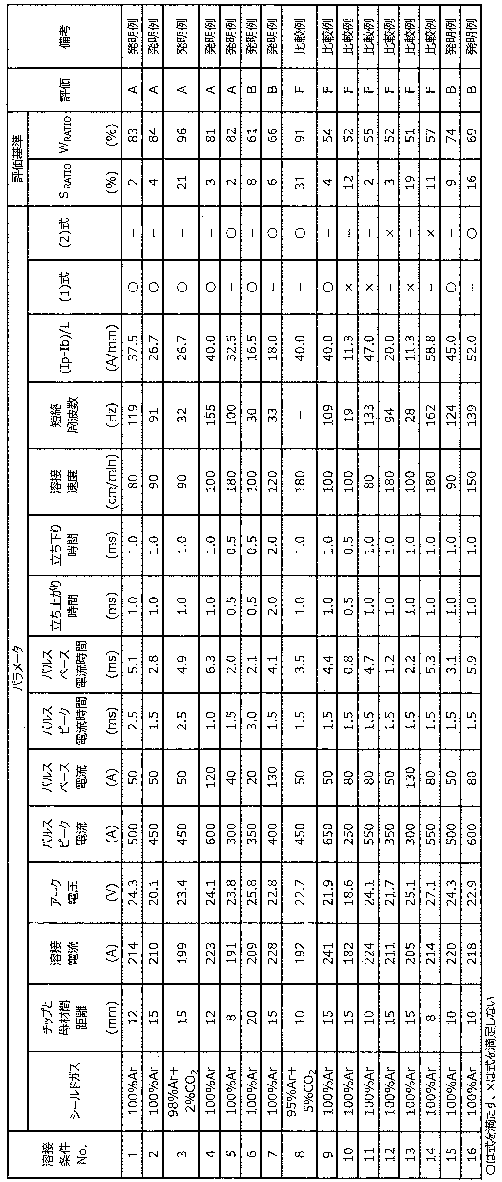
- the comparative welding conditions Nos. 8 to 14 did not satisfy either the S RATIO of 30% or less or the W RATIO of 60% or more, and therefore slag generation could not be suppressed, and good weld beads could not be obtained.
Landscapes
- Engineering & Computer Science (AREA)
- Physics & Mathematics (AREA)
- Plasma & Fusion (AREA)
- Mechanical Engineering (AREA)
- Arc Welding In General (AREA)
Abstract
Description
(a)溶接部(主に溶接ビードの表面)に付着したスラグ、
(b)溶接部に付着した溶接ヒューム、
(c)溶接によって高温に曝される鋼板の表面で生成した酸化物、
が従来から知られている。上記した(a)(b)の付着物や(c)の酸化物が溶接部に存在する部材を化成処理に供しても、これらの付着物や生成物を起点として、リン酸亜鉛結晶からなる化成処理層で覆われない領域が局部的に残留する。そのような領域に電着塗装を施しても塗膜の形成が不十分であり、塗膜の密着性が不十分となるので、耐食性が著しく低下し、腐食の発生と進展に起因する板厚の減少を引き起こす。上記した(a)(b)の付着物や(c)の酸化物の発生を防止する技術として以下の内容が検討されている。
[1] 溶接トーチ内のコンタクトチップから給電される溶接ワイヤと母材を短絡させることで接合を行うガスシールドアーク溶接方法において、
前記ガスシールドアーク溶接方法はパルスピーク電流(Ip)とパルスベース電流(Ib)が周期的に繰り返されるパルス溶接であって、前記パルス溶接のパルスピーク電流(Ip)が300A以上600A以下であり、
溶接速度(V)が80cm/min以上200cm/min以下であり、
かつ、前記溶接速度(V)が80cm/min以上120cm/min未満の場合には、前記パルスピーク電流(Ip)、前記パルスベース電流(Ib)、母材とコンタクトチップ間距離(L)、溶接速度(V)が下記(1)式を満足し、
前記溶接速度(V)が120cm/min以上200cm/min以下の場合には、前記パルスピーク電流(Ip)、前記パルスベース電流(Ib)、母材とコンタクトチップ間距離(L)、溶接速度(V)が下記(2)式を満足し、
かつシールドガスとして98体積%以上であるArガスを使用するガスシールドアーク溶接方法。
0.15V-3≦(Ip-Ib)/L≦0.1V+38・・・(1)
0.18V-5≦(Ip-Ib)/L≦0.12V+35・・・(2)
ここで、(1)式、(2)式中において、Ip(A)はパルスピーク電流、Ib(A)はパルスベース電流、L(mm)は母材とコンタクトチップ間距離、V(cm/min)は溶接速度、を指す。
[2] 前記パルス溶接のパルスベース電流(Ib)が30A以上120A以下である[1]に記載のガスシールドアーク溶接方法。
[3] [1]または[2]に記載のガスシールドアーク溶接方法を用いる溶接継手の製造方法。
図2(a)および図2(b)には、従来のMIG溶接による溶滴移行の様子を説明する概略図を示す。従来のMIG溶接の溶滴移行では、図2(a)のように溶接ワイヤ1が溶融し、細長い液柱から連続的に溶融池8へと輸送される形態が混在する。この不安定な溶滴移行を抑制するためには、溶接ワイヤ1先端から溶滴7を規則的に離脱させることが有効であると考えられるが、Arシールドガスの場合、溶接ワイヤ1に作用する電磁ピンチ力が小さく、溶滴7の離脱が困難となる。
そこで、本発明では、溶滴移行を安定化させる手段として、溶接ワイヤ1先端と母材3との間で、図3(a)の非短絡状態と、図3(b)の短絡状態とが規則的に繰り返され、短絡状態時に溶滴7が母材3へ移行する、いわゆる周期的な短絡移行により接合を完了させることが有効であることを知見した。さらに、更なる溶接実験を重ねた結果、パルスピーク電流(Ip)とパルスベース電流(Ib)の差を、コンタクトチップと母材3間距離(L)で除した因子((Ip-Ib)/L)が短絡移行のし易さであることを突き止め、(Ip-Ib)/Lを20~43の範囲とすることが好ましく、さらに種々の溶接速度に対して所定の関係を満足した時に溶接ビード6の蛇行を抑制することができることがわかった。
溶接部の耐食性を向上させるために溶接部に付着するスラグ生成量を抑制する必要があり、そのためには鋼板ならびに溶接ワイヤに含まれるSi、Mn、Ti等の酸化を抑制することが重要である。このため、シールドガスとして、Arを98体積%以上としたガスを使用する必要がある。Arを99体積%以上とすることが好ましい。上限は限定されるものではなく、Arは100体積%であって良い。
図4に本発明のアーク溶接におけるパルス電流波形を示す概略図を示す。パルス溶接とは、パルスピーク電流(Ip)とパルスベース電流(Ib)が周期的に繰り返されて溶接する方法である。パルスピーク電流(Ip)は、過小であると溶接ワイヤ1先端に形成した溶滴7を溶融池8へと押し下げる作用が得られず、短絡が不安定になり、また十分な入熱が確保できずビード形状の劣化を生じたりする場合がある。そのため、パルスピーク電流(Ip)は300A以上とする。パルスピーク電流(Ip)は、好ましくは350A以上であり、より好ましくは380A以上であり、さらに好ましくは400A以上である。一方、過大であると溶落ちを引き起こしたり、シールド不良によるスラグ生成量の増加、あるいはスパッタの増加を招く。このため、パルスピーク電流(Ip)は600A以下とする。好ましくは590A以下であり、より好ましくは580A以下であり、さらに好ましくは570A以下である。パルスピーク電流時に短絡を引き起こすため、1周期あたりのパルスピーク電流時間(tp)は0.5ms以上とすることが好ましい。1周期あたりのパルスピーク電流時間(tp)は0.7ms以上であることがより好ましく、0.8ms以上であることがさらに好ましい。1周期あたりのパルスピーク電流時間(tp)が過大になると短絡時のアーク5および溶融池8の乱れが大きくなり溶接ビード形状不良が発生する場合があるため、1周期あたりのパルスピーク電流時間(tp)は3.5ms以下とすることが望ましい。1周期あたりのパルスピーク電流時間(tp)は3.3ms以下であることがより好ましく、3.2ms以下であることがさらに好ましい。
パルスベース電流(Ib)は、過小であるとパルスベース期間でのアーク放電が不安定になりビード形状の劣化を生じ、また溶込み不足となる場合がある。このため、パルスベース電流(Ib)は30A以上とすることが好ましい。パルスベース電流(Ib)はより好ましくは35A以上である。さらに好ましくは40A以上であり、もっとも好ましくは45A以上である。一方、過大であると溶落ちを引き起こし、またパルスピーク電流(Ip)とパルスベース電流(Ib)の差を十分に確保できず、溶接ワイヤ1先端に形成した溶滴7を溶融池8へと押し下げ短絡させる作用が十分に得られず溶接が安定しない場合がある。このため、パルスベース電流(Ib)は120A以下とすることが好ましい。パルスベース電流(Ib)はより好ましくは110A以下である。さらに好ましくは100A以下であり、もっとも好ましくは90A以下である。
溶接速度(V)が大きくなると、アーク5の安定性が低下するため、周期的な短絡移行を制御することが難しくなる。特に80cm/min以上の溶接条件で上記の現象が顕著になり、以下で述べる内容に限定する必要が出てくる。一方、200cm/min超えの溶接速度(V)となる溶接条件では、所望の溶接ビード形状および溶込み形状を取得することが困難になったり、アーク5の乱れによって大気巻き込みが発生し、スラグ生成を引き起こす場合がある。そのため、本発明では対象とする溶接速度(V)を80cm/min以上200cm/min以下とする。
0.15V-3≦(Ip-Ib)/L≦0.1V+38(溶接速度Vが80cm/min以上120cm/min未満の場合)・・・(1)
0.18V-5≦(Ip-Ib)/L≦0.12V+35(溶接速度Vが120cm/min以上200cm/min以下の場合)・・・(2)
ここで、(1)式、(2)式中において、Ip(A)はパルスピーク電流、Ib(A)はパルスベース電流、L(mm)は母材とコンタクトチップ間距離、V(cm/min)は溶接速度、を指す。
Ar比率を高くしたガスシールドアーク溶接方法において周期的な短絡移行を実現するためには、パルスピーク電流(Ip)とパルスベース電流(Ib)の差と母材3とコンタクトチップ11間距離(L)を(1)、(2)式の範囲にする必要がある。溶接速度Vが80cm/min以上120cm/min未満の場合、(Ip-Ib)/Lが0.15V-3未満では、アーク5のふらつきに影響を受けない短絡移行の実現が困難となるため、0.15V-3以上とする必要がある。好ましくは、0.15V-2以上であり、さらに好ましくは0.15V-1以上である。一方、0.1V+38を超えると、短絡時のアーク5および溶融池8の乱れが大きくなり溶接ビード形状不良が発生する場合があるため、0.1V+38以下とする必要がある。好ましくは、0.1V+36以下であり、より好ましくは0.1V+34以下である。また、溶接速度Vが120cm/min以上200cm/min以下の場合、(Ip-Ib)/Lが0.18V-5未満では、アーク5のふらつきに影響を受けない短絡移行の実現が困難となるため、0.18V-5以上とする必要がある。好ましくは、0.18V-4以上であり、より好ましくは0.18V-3以上である。一方、0.12V+35を超えると、短絡時のアーク5および溶融池8の乱れが大きくなり溶接ビード形状不良が発生する場合があるため、0.12V+35以下とする必要がある。好ましくは、0.12V+33以下であり、より好ましくは0.12V+31以下である。
図5は溶接ビードにおけるビード面積およびスラグ被覆面積を示す概略図である。図5に示すようなビード表面積SBEADとスラグ被覆表面積SSLAGは、溶接ビード6のビード始終端部10(各々長さ15mm)を除いた領域の表面を真上から撮影し、溶接ビード6およびスラグの上面からの投影面積を測定して算出する。溶接ビード6の長さが130mm未満である場合は、ビード始終端部10を除く全長の表面を撮影する。溶接ビード6の長さが130mm以上である場合は、ビード始終端部10を除いて任意の部位(長さ100mm)の表面を撮影する。算出したスラグ表面積SSLAGの値をビード表面積SBEADの値で除すことでスラグ被覆面積率SRATIOを求めた。SRATIOが30%以下を合格とした。
図6はビード幅の最小値および最大値を示す概略図である。同様に、図6で示すようなビード幅の最大値WMAXと最小値WMINは、溶接ビード6のビード始終端部10(各々長さ15mm)を除いた領域の表面を撮影し、得られた写真を解析して測定した。溶接ビード6の長さが130mm未満であった場合は、ビード始終端部10を除く全長の表面を撮影した。溶接ビード6の長さが130mm以上であった場合は、ビード始終端部10を除いて任意の部位(長さ100mm)の表面を撮影した。算出したビード幅の最小値Wminを最大値Wmaxで除すことでビード幅比率WRATIOを求めた。WRATIOが60%以上を合格とした。

2 溶接トーチ
3 母材
5 アーク
6 溶接ビード
7 溶滴
8 溶融池
10 ビード始終端部
11 コンタクトチップ
tup 立ち上がり時間
tp パルスピーク電流時間
tdown 立ち下がり時間
tb パルスベース電流時間
tup+tp+tdown+tb パルス1周期
SBEAD ビード表面積
SSLAG スラグ被覆表面積
WMAX ビード幅の最大値
Wmin ビード幅の最小値
Claims (3)
- 溶接トーチ内のコンタクトチップから給電される溶接ワイヤと母材を短絡させることで接合を行うガスシールドアーク溶接方法において、
前記ガスシールドアーク溶接方法はパルスピーク電流(Ip)とパルスベース電流(Ib)が周期的に繰り返されるパルス溶接であって、前記パルス溶接のパルスピーク電流(Ip)が300A以上600A以下であり、
溶接速度(V)が80cm/min以上200cm/min以下であり、
かつ、前記溶接速度(V)が80cm/min以上120cm/min未満の場合には、前記パルスピーク電流(Ip)、前記パルスベース電流(Ib)、母材とコンタクトチップ間距離(L)、溶接速度(V)が下記(1)式を満足し、
前記溶接速度(V)が120cm/min以上200cm/min以下の場合には、前記パルスピーク電流(Ip)、前記パルスベース電流(Ib)、母材とコンタクトチップ間距離(L)、溶接速度(V)が下記(2)式を満足し、
かつシールドガスとして98体積%以上であるArガスを使用するガスシールドアーク溶接方法。
0.15V-3≦(Ip-Ib)/L≦0.1V+38・・・(1)
0.18V-5≦(Ip-Ib)/L≦0.12V+35・・・(2)
ここで、(1)式、(2)式中において、Ip(A)はパルスピーク電流、Ib(A)はパルスベース電流、L(mm)は母材とコンタクトチップ間距離、V(cm/min)は溶接速度、を指す。 - 前記パルス溶接のパルスベース電流(Ib)が30A以上120A以下である請求項1に記載のガスシールドアーク溶接方法。
- 請求項1または2に記載のガスシールドアーク溶接方法を用いる溶接継手の製造方法。
Priority Applications (5)
| Application Number | Priority Date | Filing Date | Title |
|---|---|---|---|
| KR1020257013044A KR20250069667A (ko) | 2022-10-31 | 2023-09-11 | 가스 실드 아크 용접 방법 및 용접 조인트의 제조 방법 |
| CN202380074005.6A CN120129583A (zh) | 2022-10-31 | 2023-09-11 | 气体保护电弧焊接方法以及焊接接头的制造方法 |
| JP2023570390A JP7435931B1 (ja) | 2022-10-31 | 2023-09-11 | ガスシールドアーク溶接方法および溶接継手の製造方法 |
| EP23885378.2A EP4570408A4 (en) | 2022-10-31 | 2023-09-11 | GAS-PROTECTED ARC WELDING PROCESS AND PROCESS FOR PRODUCING WELDED JOINT |
| MX2025004721A MX2025004721A (es) | 2022-10-31 | 2025-04-23 | Metodo de soldadura por arco con proteccion de gas y metodo para la fabricacion de uniones soldadas |
Applications Claiming Priority (2)
| Application Number | Priority Date | Filing Date | Title |
|---|---|---|---|
| JP2022-174337 | 2022-10-31 | ||
| JP2022174337 | 2022-10-31 |
Publications (1)
| Publication Number | Publication Date |
|---|---|
| WO2024095612A1 true WO2024095612A1 (ja) | 2024-05-10 |
Family
ID=90930203
Family Applications (1)
| Application Number | Title | Priority Date | Filing Date |
|---|---|---|---|
| PCT/JP2023/033083 Ceased WO2024095612A1 (ja) | 2022-10-31 | 2023-09-11 | ガスシールドアーク溶接方法および溶接継手の製造方法 |
Country Status (1)
| Country | Link |
|---|---|
| WO (1) | WO2024095612A1 (ja) |
Cited By (1)
| Publication number | Priority date | Publication date | Assignee | Title |
|---|---|---|---|---|
| WO2026083719A1 (ja) * | 2024-10-15 | 2026-04-23 | Jfeスチール株式会社 | ガスシールドアーク溶接継手の製造方法 |
Citations (6)
| Publication number | Priority date | Publication date | Assignee | Title |
|---|---|---|---|---|
| JPH0833997A (ja) | 1994-07-21 | 1996-02-06 | Sumitomo Metal Ind Ltd | 溶接部およびその近傍の塗装後耐食性を高めるガスシールドメタルアーク溶接方法 |
| JPH0920994A (ja) | 1995-07-03 | 1997-01-21 | Sumitomo Metal Ind Ltd | アーク溶接部及びその近傍の塗装後耐食性改善方法 |
| JPH0985443A (ja) * | 1995-09-22 | 1997-03-31 | Toyota Autom Loom Works Ltd | アーク溶接装置及び溶接条件設定方法 |
| JP5549615B2 (ja) | 2011-02-04 | 2014-07-16 | Jfeスチール株式会社 | 鋼製部材の化成処理方法、電着塗装を施した鋼製塗装部材の製造方法、および鋼製塗装部材 |
| WO2021085544A1 (ja) * | 2019-10-31 | 2021-05-06 | Jfeスチール株式会社 | Mig溶接方法 |
| WO2021210335A1 (ja) * | 2020-04-15 | 2021-10-21 | Jfeスチール株式会社 | アーク溶接継手およびアーク溶接方法 |
-
2023
- 2023-09-11 WO PCT/JP2023/033083 patent/WO2024095612A1/ja not_active Ceased
Patent Citations (6)
| Publication number | Priority date | Publication date | Assignee | Title |
|---|---|---|---|---|
| JPH0833997A (ja) | 1994-07-21 | 1996-02-06 | Sumitomo Metal Ind Ltd | 溶接部およびその近傍の塗装後耐食性を高めるガスシールドメタルアーク溶接方法 |
| JPH0920994A (ja) | 1995-07-03 | 1997-01-21 | Sumitomo Metal Ind Ltd | アーク溶接部及びその近傍の塗装後耐食性改善方法 |
| JPH0985443A (ja) * | 1995-09-22 | 1997-03-31 | Toyota Autom Loom Works Ltd | アーク溶接装置及び溶接条件設定方法 |
| JP5549615B2 (ja) | 2011-02-04 | 2014-07-16 | Jfeスチール株式会社 | 鋼製部材の化成処理方法、電着塗装を施した鋼製塗装部材の製造方法、および鋼製塗装部材 |
| WO2021085544A1 (ja) * | 2019-10-31 | 2021-05-06 | Jfeスチール株式会社 | Mig溶接方法 |
| WO2021210335A1 (ja) * | 2020-04-15 | 2021-10-21 | Jfeスチール株式会社 | アーク溶接継手およびアーク溶接方法 |
Cited By (1)
| Publication number | Priority date | Publication date | Assignee | Title |
|---|---|---|---|---|
| WO2026083719A1 (ja) * | 2024-10-15 | 2026-04-23 | Jfeスチール株式会社 | ガスシールドアーク溶接継手の製造方法 |
Similar Documents
| Publication | Publication Date | Title |
|---|---|---|
| JP7238990B2 (ja) | アーク溶接継手およびアーク溶接方法 | |
| CN108067761B (zh) | 具有碱土金属的焊接电极焊丝 | |
| US11426824B2 (en) | Aluminum-containing welding electrode | |
| JP7574948B2 (ja) | 重ね隅肉アーク溶接方法および溶接継手の製造方法 | |
| KR102910129B1 (ko) | 아크 용접 이음매 및 아크 용접 방법 | |
| JP2002239725A (ja) | 鋼板のガスシールドアーク溶接方法 | |
| JP7060159B2 (ja) | Mig溶接方法 | |
| WO2024095612A1 (ja) | ガスシールドアーク溶接方法および溶接継手の製造方法 | |
| WO2024095613A1 (ja) | ガスシールドアーク溶接方法および溶接継手の製造方法 | |
| WO2022230905A1 (ja) | アーク溶接継手およびアーク溶接方法 | |
| JP7435931B1 (ja) | ガスシールドアーク溶接方法および溶接継手の製造方法 | |
| JP7435932B1 (ja) | ガスシールドアーク溶接方法および溶接継手の製造方法 | |
| JP7677536B2 (ja) | アーク溶接継手およびその製造方法 | |
| JP7508016B1 (ja) | アーク溶接継手およびその製造方法 | |
| WO2024224713A1 (ja) | アーク溶接継手およびその製造方法 | |
| WO2026083719A1 (ja) | ガスシールドアーク溶接継手の製造方法 | |
| JP2025151923A (ja) | ガスシールドアーク溶接方法、ガスシールドアーク溶接システム、溶接金属の製造方法、および溶接ワイヤ | |
| WO2022230904A1 (ja) | アーク溶接継手およびアーク溶接方法 | |
| KR20030079219A (ko) | Mag 용접용 강 와이어 및 이것을 사용한 mag 용접방법 |
Legal Events
| Date | Code | Title | Description |
|---|---|---|---|
| ENP | Entry into the national phase |
Ref document number: 2023570390 Country of ref document: JP Kind code of ref document: A |
|
| 121 | Ep: the epo has been informed by wipo that ep was designated in this application |
Ref document number: 23885378 Country of ref document: EP Kind code of ref document: A1 |
|
| WWE | Wipo information: entry into national phase |
Ref document number: 2023885378 Country of ref document: EP |
|
| ENP | Entry into the national phase |
Ref document number: 2023885378 Country of ref document: EP Effective date: 20250311 |
|
| WWE | Wipo information: entry into national phase |
Ref document number: 202380074005.6 Country of ref document: CN |
|
| ENP | Entry into the national phase |
Ref document number: 20257013044 Country of ref document: KR Kind code of ref document: A |
|
| WWE | Wipo information: entry into national phase |
Ref document number: 1020257013044 Country of ref document: KR |
|
| WWE | Wipo information: entry into national phase |
Ref document number: 2501002567 Country of ref document: TH |
|
| WWE | Wipo information: entry into national phase |
Ref document number: 202517039141 Country of ref document: IN |
|
| WWP | Wipo information: published in national office |
Ref document number: 202517039141 Country of ref document: IN |
|
| NENP | Non-entry into the national phase |
Ref country code: DE |
|
| WWP | Wipo information: published in national office |
Ref document number: 202380074005.6 Country of ref document: CN |
|
| WWP | Wipo information: published in national office |
Ref document number: 2023885378 Country of ref document: EP |