WO2024100939A1 - 熱延鋼板、電縫鋼管および角形鋼管ならびにラインパイプおよび建築構造物 - Google Patents
熱延鋼板、電縫鋼管および角形鋼管ならびにラインパイプおよび建築構造物 Download PDFInfo
- Publication number
- WO2024100939A1 WO2024100939A1 PCT/JP2023/027298 JP2023027298W WO2024100939A1 WO 2024100939 A1 WO2024100939 A1 WO 2024100939A1 JP 2023027298 W JP2023027298 W JP 2023027298W WO 2024100939 A1 WO2024100939 A1 WO 2024100939A1
- Authority
- WO
- WIPO (PCT)
- Prior art keywords
- less
- steel pipe
- hot
- electric resistance
- resistance welded
- Prior art date
- Legal status (The legal status is an assumption and is not a legal conclusion. Google has not performed a legal analysis and makes no representation as to the accuracy of the status listed.)
- Ceased
Links
Images

Classifications
-
- C—CHEMISTRY; METALLURGY
- C22—METALLURGY; FERROUS OR NON-FERROUS ALLOYS; TREATMENT OF ALLOYS OR NON-FERROUS METALS
- C22C—ALLOYS
- C22C38/00—Ferrous alloys, e.g. steel alloys
- C22C38/06—Ferrous alloys, e.g. steel alloys containing aluminium
-
- B—PERFORMING OPERATIONS; TRANSPORTING
- B21—MECHANICAL METAL-WORKING WITHOUT ESSENTIALLY REMOVING MATERIAL; PUNCHING METAL
- B21B—ROLLING OF METAL
- B21B1/00—Metal-rolling methods or mills for making semi-finished products of solid or profiled cross-section; Sequence of operations in milling trains; Layout of rolling-mill plant, e.g. grouping of stands; Succession of passes or of sectional pass alternations
- B21B1/22—Metal-rolling methods or mills for making semi-finished products of solid or profiled cross-section; Sequence of operations in milling trains; Layout of rolling-mill plant, e.g. grouping of stands; Succession of passes or of sectional pass alternations for rolling plates, strips, bands or sheets of indefinite length
-
- B—PERFORMING OPERATIONS; TRANSPORTING
- B21—MECHANICAL METAL-WORKING WITHOUT ESSENTIALLY REMOVING MATERIAL; PUNCHING METAL
- B21C—MANUFACTURE OF METAL SHEETS, WIRE, RODS, TUBES, PROFILES OR LIKE SEMI-MANUFACTURED PRODUCTS OTHERWISE THAN BY ROLLING; AUXILIARY OPERATIONS USED IN CONNECTION WITH METAL-WORKING WITHOUT ESSENTIALLY REMOVING MATERIAL
- B21C37/00—Manufacture of metal sheets, rods, wire, tubes, profiles or like semi-manufactured products, not otherwise provided for; Manufacture of tubes of special shape
- B21C37/06—Manufacture of metal sheets, rods, wire, tubes, profiles or like semi-manufactured products, not otherwise provided for; Manufacture of tubes of special shape of tubes or metal hoses; Combined procedures for making tubes, e.g. for making multi-wall tubes
- B21C37/15—Making tubes of special shape; Making tube fittings
-
- C—CHEMISTRY; METALLURGY
- C21—METALLURGY OF IRON
- C21D—MODIFYING THE PHYSICAL STRUCTURE OF FERROUS METALS; GENERAL DEVICES FOR HEAT TREATMENT OF FERROUS OR NON-FERROUS METALS OR ALLOYS; MAKING METAL MALLEABLE, e.g. BY DECARBURISATION OR TEMPERING
- C21D6/00—Heat treatment of ferrous alloys
- C21D6/005—Heat treatment of ferrous alloys containing Mn
-
- C—CHEMISTRY; METALLURGY
- C21—METALLURGY OF IRON
- C21D—MODIFYING THE PHYSICAL STRUCTURE OF FERROUS METALS; GENERAL DEVICES FOR HEAT TREATMENT OF FERROUS OR NON-FERROUS METALS OR ALLOYS; MAKING METAL MALLEABLE, e.g. BY DECARBURISATION OR TEMPERING
- C21D8/00—Modifying the physical properties of ferrous metals or ferrous alloys by deformation combined with, or followed by, heat treatment
- C21D8/02—Modifying the physical properties of ferrous metals or ferrous alloys by deformation combined with, or followed by, heat treatment during manufacturing of plates or strips
-
- C—CHEMISTRY; METALLURGY
- C21—METALLURGY OF IRON
- C21D—MODIFYING THE PHYSICAL STRUCTURE OF FERROUS METALS; GENERAL DEVICES FOR HEAT TREATMENT OF FERROUS OR NON-FERROUS METALS OR ALLOYS; MAKING METAL MALLEABLE, e.g. BY DECARBURISATION OR TEMPERING
- C21D8/00—Modifying the physical properties of ferrous metals or ferrous alloys by deformation combined with, or followed by, heat treatment
- C21D8/02—Modifying the physical properties of ferrous metals or ferrous alloys by deformation combined with, or followed by, heat treatment during manufacturing of plates or strips
- C21D8/0221—Modifying the physical properties of ferrous metals or ferrous alloys by deformation combined with, or followed by, heat treatment during manufacturing of plates or strips characterised by the working steps
- C21D8/0226—Hot rolling
-
- C—CHEMISTRY; METALLURGY
- C21—METALLURGY OF IRON
- C21D—MODIFYING THE PHYSICAL STRUCTURE OF FERROUS METALS; GENERAL DEVICES FOR HEAT TREATMENT OF FERROUS OR NON-FERROUS METALS OR ALLOYS; MAKING METAL MALLEABLE, e.g. BY DECARBURISATION OR TEMPERING
- C21D8/00—Modifying the physical properties of ferrous metals or ferrous alloys by deformation combined with, or followed by, heat treatment
- C21D8/02—Modifying the physical properties of ferrous metals or ferrous alloys by deformation combined with, or followed by, heat treatment during manufacturing of plates or strips
- C21D8/0247—Modifying the physical properties of ferrous metals or ferrous alloys by deformation combined with, or followed by, heat treatment during manufacturing of plates or strips characterised by the heat treatment
- C21D8/0263—Modifying the physical properties of ferrous metals or ferrous alloys by deformation combined with, or followed by, heat treatment during manufacturing of plates or strips characterised by the heat treatment following hot rolling
-
- C—CHEMISTRY; METALLURGY
- C21—METALLURGY OF IRON
- C21D—MODIFYING THE PHYSICAL STRUCTURE OF FERROUS METALS; GENERAL DEVICES FOR HEAT TREATMENT OF FERROUS OR NON-FERROUS METALS OR ALLOYS; MAKING METAL MALLEABLE, e.g. BY DECARBURISATION OR TEMPERING
- C21D8/00—Modifying the physical properties of ferrous metals or ferrous alloys by deformation combined with, or followed by, heat treatment
- C21D8/02—Modifying the physical properties of ferrous metals or ferrous alloys by deformation combined with, or followed by, heat treatment during manufacturing of plates or strips
- C21D8/04—Modifying the physical properties of ferrous metals or ferrous alloys by deformation combined with, or followed by, heat treatment during manufacturing of plates or strips to produce plates or strips for drawing, e.g. for deep-drawing
- C21D8/0421—Modifying the physical properties of ferrous metals or ferrous alloys by deformation combined with, or followed by, heat treatment during manufacturing of plates or strips to produce plates or strips for drawing, e.g. for deep-drawing characterised by the working steps
- C21D8/0426—Hot rolling
-
- C—CHEMISTRY; METALLURGY
- C21—METALLURGY OF IRON
- C21D—MODIFYING THE PHYSICAL STRUCTURE OF FERROUS METALS; GENERAL DEVICES FOR HEAT TREATMENT OF FERROUS OR NON-FERROUS METALS OR ALLOYS; MAKING METAL MALLEABLE, e.g. BY DECARBURISATION OR TEMPERING
- C21D8/00—Modifying the physical properties of ferrous metals or ferrous alloys by deformation combined with, or followed by, heat treatment
- C21D8/10—Modifying the physical properties of ferrous metals or ferrous alloys by deformation combined with, or followed by, heat treatment during manufacturing of tubular bodies
-
- C—CHEMISTRY; METALLURGY
- C21—METALLURGY OF IRON
- C21D—MODIFYING THE PHYSICAL STRUCTURE OF FERROUS METALS; GENERAL DEVICES FOR HEAT TREATMENT OF FERROUS OR NON-FERROUS METALS OR ALLOYS; MAKING METAL MALLEABLE, e.g. BY DECARBURISATION OR TEMPERING
- C21D9/00—Heat treatment, e.g. annealing, hardening, quenching or tempering, adapted for particular articles; Furnaces therefor
- C21D9/08—Heat treatment, e.g. annealing, hardening, quenching or tempering, adapted for particular articles; Furnaces therefor for tubular bodies or pipes
-
- C—CHEMISTRY; METALLURGY
- C21—METALLURGY OF IRON
- C21D—MODIFYING THE PHYSICAL STRUCTURE OF FERROUS METALS; GENERAL DEVICES FOR HEAT TREATMENT OF FERROUS OR NON-FERROUS METALS OR ALLOYS; MAKING METAL MALLEABLE, e.g. BY DECARBURISATION OR TEMPERING
- C21D9/00—Heat treatment, e.g. annealing, hardening, quenching or tempering, adapted for particular articles; Furnaces therefor
- C21D9/08—Heat treatment, e.g. annealing, hardening, quenching or tempering, adapted for particular articles; Furnaces therefor for tubular bodies or pipes
- C21D9/085—Cooling or quenching
-
- C—CHEMISTRY; METALLURGY
- C21—METALLURGY OF IRON
- C21D—MODIFYING THE PHYSICAL STRUCTURE OF FERROUS METALS; GENERAL DEVICES FOR HEAT TREATMENT OF FERROUS OR NON-FERROUS METALS OR ALLOYS; MAKING METAL MALLEABLE, e.g. BY DECARBURISATION OR TEMPERING
- C21D9/00—Heat treatment, e.g. annealing, hardening, quenching or tempering, adapted for particular articles; Furnaces therefor
- C21D9/46—Heat treatment, e.g. annealing, hardening, quenching or tempering, adapted for particular articles; Furnaces therefor for sheet metals
-
- C—CHEMISTRY; METALLURGY
- C21—METALLURGY OF IRON
- C21D—MODIFYING THE PHYSICAL STRUCTURE OF FERROUS METALS; GENERAL DEVICES FOR HEAT TREATMENT OF FERROUS OR NON-FERROUS METALS OR ALLOYS; MAKING METAL MALLEABLE, e.g. BY DECARBURISATION OR TEMPERING
- C21D9/00—Heat treatment, e.g. annealing, hardening, quenching or tempering, adapted for particular articles; Furnaces therefor
- C21D9/50—Heat treatment, e.g. annealing, hardening, quenching or tempering, adapted for particular articles; Furnaces therefor for welded joints
-
- C—CHEMISTRY; METALLURGY
- C22—METALLURGY; FERROUS OR NON-FERROUS ALLOYS; TREATMENT OF ALLOYS OR NON-FERROUS METALS
- C22C—ALLOYS
- C22C38/00—Ferrous alloys, e.g. steel alloys
- C22C38/002—Ferrous alloys, e.g. steel alloys containing In, Mg, or other elements not provided for in one single group C22C38/001 - C22C38/60
-
- C—CHEMISTRY; METALLURGY
- C22—METALLURGY; FERROUS OR NON-FERROUS ALLOYS; TREATMENT OF ALLOYS OR NON-FERROUS METALS
- C22C—ALLOYS
- C22C38/00—Ferrous alloys, e.g. steel alloys
- C22C38/005—Ferrous alloys, e.g. steel alloys containing rare earths, i.e. Sc, Y, Lanthanides
-
- C—CHEMISTRY; METALLURGY
- C22—METALLURGY; FERROUS OR NON-FERROUS ALLOYS; TREATMENT OF ALLOYS OR NON-FERROUS METALS
- C22C—ALLOYS
- C22C38/00—Ferrous alloys, e.g. steel alloys
- C22C38/02—Ferrous alloys, e.g. steel alloys containing silicon
-
- C—CHEMISTRY; METALLURGY
- C22—METALLURGY; FERROUS OR NON-FERROUS ALLOYS; TREATMENT OF ALLOYS OR NON-FERROUS METALS
- C22C—ALLOYS
- C22C38/00—Ferrous alloys, e.g. steel alloys
- C22C38/04—Ferrous alloys, e.g. steel alloys containing manganese
-
- C—CHEMISTRY; METALLURGY
- C22—METALLURGY; FERROUS OR NON-FERROUS ALLOYS; TREATMENT OF ALLOYS OR NON-FERROUS METALS
- C22C—ALLOYS
- C22C38/00—Ferrous alloys, e.g. steel alloys
- C22C38/08—Ferrous alloys, e.g. steel alloys containing nickel
-
- C—CHEMISTRY; METALLURGY
- C22—METALLURGY; FERROUS OR NON-FERROUS ALLOYS; TREATMENT OF ALLOYS OR NON-FERROUS METALS
- C22C—ALLOYS
- C22C38/00—Ferrous alloys, e.g. steel alloys
- C22C38/12—Ferrous alloys, e.g. steel alloys containing tungsten, tantalum, molybdenum, vanadium, or niobium
-
- C—CHEMISTRY; METALLURGY
- C22—METALLURGY; FERROUS OR NON-FERROUS ALLOYS; TREATMENT OF ALLOYS OR NON-FERROUS METALS
- C22C—ALLOYS
- C22C38/00—Ferrous alloys, e.g. steel alloys
- C22C38/14—Ferrous alloys, e.g. steel alloys containing titanium or zirconium
-
- C—CHEMISTRY; METALLURGY
- C22—METALLURGY; FERROUS OR NON-FERROUS ALLOYS; TREATMENT OF ALLOYS OR NON-FERROUS METALS
- C22C—ALLOYS
- C22C38/00—Ferrous alloys, e.g. steel alloys
- C22C38/16—Ferrous alloys, e.g. steel alloys containing copper
-
- C—CHEMISTRY; METALLURGY
- C22—METALLURGY; FERROUS OR NON-FERROUS ALLOYS; TREATMENT OF ALLOYS OR NON-FERROUS METALS
- C22C—ALLOYS
- C22C38/00—Ferrous alloys, e.g. steel alloys
- C22C38/18—Ferrous alloys, e.g. steel alloys containing chromium
- C22C38/22—Ferrous alloys, e.g. steel alloys containing chromium with molybdenum or tungsten
-
- C—CHEMISTRY; METALLURGY
- C22—METALLURGY; FERROUS OR NON-FERROUS ALLOYS; TREATMENT OF ALLOYS OR NON-FERROUS METALS
- C22C—ALLOYS
- C22C38/00—Ferrous alloys, e.g. steel alloys
- C22C38/18—Ferrous alloys, e.g. steel alloys containing chromium
- C22C38/24—Ferrous alloys, e.g. steel alloys containing chromium with vanadium
-
- C—CHEMISTRY; METALLURGY
- C22—METALLURGY; FERROUS OR NON-FERROUS ALLOYS; TREATMENT OF ALLOYS OR NON-FERROUS METALS
- C22C—ALLOYS
- C22C38/00—Ferrous alloys, e.g. steel alloys
- C22C38/18—Ferrous alloys, e.g. steel alloys containing chromium
- C22C38/26—Ferrous alloys, e.g. steel alloys containing chromium with niobium or tantalum
-
- C—CHEMISTRY; METALLURGY
- C22—METALLURGY; FERROUS OR NON-FERROUS ALLOYS; TREATMENT OF ALLOYS OR NON-FERROUS METALS
- C22C—ALLOYS
- C22C38/00—Ferrous alloys, e.g. steel alloys
- C22C38/18—Ferrous alloys, e.g. steel alloys containing chromium
- C22C38/28—Ferrous alloys, e.g. steel alloys containing chromium with titanium or zirconium
-
- C—CHEMISTRY; METALLURGY
- C22—METALLURGY; FERROUS OR NON-FERROUS ALLOYS; TREATMENT OF ALLOYS OR NON-FERROUS METALS
- C22C—ALLOYS
- C22C38/00—Ferrous alloys, e.g. steel alloys
- C22C38/18—Ferrous alloys, e.g. steel alloys containing chromium
- C22C38/38—Ferrous alloys, e.g. steel alloys containing chromium with more than 1.5% by weight of manganese
-
- B—PERFORMING OPERATIONS; TRANSPORTING
- B21—MECHANICAL METAL-WORKING WITHOUT ESSENTIALLY REMOVING MATERIAL; PUNCHING METAL
- B21C—MANUFACTURE OF METAL SHEETS, WIRE, RODS, TUBES, PROFILES OR LIKE SEMI-MANUFACTURED PRODUCTS OTHERWISE THAN BY ROLLING; AUXILIARY OPERATIONS USED IN CONNECTION WITH METAL-WORKING WITHOUT ESSENTIALLY REMOVING MATERIAL
- B21C37/00—Manufacture of metal sheets, rods, wire, tubes, profiles or like semi-manufactured products, not otherwise provided for; Manufacture of tubes of special shape
- B21C37/06—Manufacture of metal sheets, rods, wire, tubes, profiles or like semi-manufactured products, not otherwise provided for; Manufacture of tubes of special shape of tubes or metal hoses; Combined procedures for making tubes, e.g. for making multi-wall tubes
- B21C37/08—Making tubes with welded or soldered seams
-
- C—CHEMISTRY; METALLURGY
- C21—METALLURGY OF IRON
- C21D—MODIFYING THE PHYSICAL STRUCTURE OF FERROUS METALS; GENERAL DEVICES FOR HEAT TREATMENT OF FERROUS OR NON-FERROUS METALS OR ALLOYS; MAKING METAL MALLEABLE, e.g. BY DECARBURISATION OR TEMPERING
- C21D2211/00—Microstructure comprising significant phases
- C21D2211/001—Austenite
-
- C—CHEMISTRY; METALLURGY
- C21—METALLURGY OF IRON
- C21D—MODIFYING THE PHYSICAL STRUCTURE OF FERROUS METALS; GENERAL DEVICES FOR HEAT TREATMENT OF FERROUS OR NON-FERROUS METALS OR ALLOYS; MAKING METAL MALLEABLE, e.g. BY DECARBURISATION OR TEMPERING
- C21D2211/00—Microstructure comprising significant phases
- C21D2211/002—Bainite
-
- C—CHEMISTRY; METALLURGY
- C21—METALLURGY OF IRON
- C21D—MODIFYING THE PHYSICAL STRUCTURE OF FERROUS METALS; GENERAL DEVICES FOR HEAT TREATMENT OF FERROUS OR NON-FERROUS METALS OR ALLOYS; MAKING METAL MALLEABLE, e.g. BY DECARBURISATION OR TEMPERING
- C21D2211/00—Microstructure comprising significant phases
- C21D2211/005—Ferrite
-
- C—CHEMISTRY; METALLURGY
- C21—METALLURGY OF IRON
- C21D—MODIFYING THE PHYSICAL STRUCTURE OF FERROUS METALS; GENERAL DEVICES FOR HEAT TREATMENT OF FERROUS OR NON-FERROUS METALS OR ALLOYS; MAKING METAL MALLEABLE, e.g. BY DECARBURISATION OR TEMPERING
- C21D2211/00—Microstructure comprising significant phases
- C21D2211/008—Martensite
-
- C—CHEMISTRY; METALLURGY
- C21—METALLURGY OF IRON
- C21D—MODIFYING THE PHYSICAL STRUCTURE OF FERROUS METALS; GENERAL DEVICES FOR HEAT TREATMENT OF FERROUS OR NON-FERROUS METALS OR ALLOYS; MAKING METAL MALLEABLE, e.g. BY DECARBURISATION OR TEMPERING
- C21D2211/00—Microstructure comprising significant phases
- C21D2211/009—Pearlite
Definitions
- the present invention relates to electric resistance welded steel pipes and square steel pipes, as well as hot-rolled steel sheets used as the raw materials for these pipes, and line pipes and building structures that use these pipes.
- Electric resistance welded steel pipes and roll-formed square steel pipes used in line pipes and building structures are required to have high strength to withstand the internal pressure of the fluid flowing inside and external loads. At the same time, they are also required to have high buckling resistance from the perspective of earthquake resistance.
- Electric welded steel pipes and roll-formed rectangular steel pipes are made from hot-rolled steel plate (hot-rolled steel strip). This is cold rolled to form a cylindrical open pipe, and the butt joint is electric resistance welded (sometimes referred to as electric resistance welding) to form a round steel pipe.
- Electric welded steel pipes are manufactured by adjusting the outer diameter and roundness using a forming roll placed on the outside of this round steel pipe.
- Square steel pipes are manufactured by further roll-forming this round steel pipe into a square shape using a roll with a desired polygonal hole shape. This method of manufacturing rectangular steel pipes by roll forming has the advantage of being more productive than the method of manufacturing steel pipes by press bending.
- Patent Document 1 discloses a high-strength hot-rolled steel sheet with excellent uniform elongation after cold working, which contains, by weight, 0.04-0.25% C, 0.0050-0.0150% N, and 0.003-0.050% Ti, has a carbon equivalent (Ceq.) of 0.10-0.45% calculated by a specific formula, has a pearlite phase with an area fraction of 5-20%, and further has TiN with an average particle size of 1-30 ⁇ m dispersed in the steel at a ratio of 0.0008-0.015% by weight.
- C carbon equivalent
- Patent Document 2 discloses a thick, hot-rolled steel sheet for rectangular steel pipes for architectural structural members with a low yield ratio, which has a composition, by mass%, of C: 0.07-0.18%, Mn: 0.3-1.5%, P: 0.03% or less, S: 0.015% or less, Al: 0.01-0.06%, N: 0.006% or less, with the balance being Fe and unavoidable impurities, and has a structure in which ferrite is the main phase and pearlite or pearlite and bainite are present as the second phase, the second phase frequency defined by a specific formula is 0.20-0.42, and the average crystal grain size including the main phase and the second phase is 7-15 ⁇ m.
- Patent Document 3 discloses an electric resistance welded steel pipe for line pipe with a low yield ratio, characterized in that dislocations introduced during the forming process are pinned by carbon atom clusters, fine carbides, and Nb carbides due to tempering after pipe making.
- Patent Document 4 discloses a square steel pipe with a low yield ratio, made from a hot-rolled steel sheet characterized by having ferrite as the main phase, a second phase frequency of 0.05 to 0.15, a second phase area ratio of 3 to 15%, and an average crystal grain size of the main phase and the second phase at 1/4 the thickness of the steel sheet of 10 to 25 ⁇ m.
- Patent Document 5 discloses a square steel pipe manufactured by hot forming, characterized by high deformability and toughness.
- the present invention has been made in consideration of the above circumstances, and has an object to provide electric resistance welded steel pipes and square steel pipes having excellent buckling resistance, as well as hot-rolled steel sheets used as raw materials for these pipes. Another object of the present invention is to provide a line pipe and a building structure using the above-mentioned electric resistance welded steel pipe and square steel pipe.
- t represents the wall thickness (mm) of the electric resistance welded steel pipe or square steel pipe
- D represents the outer diameter (mm) of the electric resistance welded steel pipe
- B represents the side length (mm) of the square steel pipe
- ⁇ max represents the maximum stress intensity (N/mm 2 ) in the axial compression test.
- the hot-rolled steel plate of the above-mentioned material includes a hot-rolled steel strip.
- the buckling resistance of cold-formed electric resistance welded steel pipes and cold-formed rectangular steel pipes can be improved by giving them a low yield ratio and reducing the logarithmic standard deviation of the equivalent plastic strain distribution during deformation.
- the smaller the logarithmic standard deviation the smaller the variation in plastic strain during deformation, the more uniform the distribution of plastic strain, and the less likely strain will concentrate in a specific part, making it less likely that local buckling will occur.
- the electric resistance welded steel pipes and rectangular steel pipes can be obtained by using hot-rolled steel sheets with a small logarithmic standard deviation of the equivalent plastic strain distribution during deformation as their raw material.
- the present invention has been completed based on these findings and comprises the following: [1]
- the component composition is, in mass%, C: 0.030% or more and 0.300% or less, Si: 0.010% or more and 0.500% or less, Mn: 0.30% or more and 2.50% or less, P: 0.050% or less, S: 0.0200% or less, Al: 0.005% or more and 0.100% or less, N: 0.0100% or less, with the balance being Fe and unavoidable impurities;
- the steel structure at the center of the plate thickness is The total volume fraction of ferrite and bainite is 70% or more and 98% or less,
- the balance is one or more selected from pearlite, martensite, and austenite,
- the average crystal grain size is 15.0 ⁇ m or less,
- the CP value calculated by the following formula (1) is 0.090 or less,
- the tensile strength is 400 MPa or more, A hot-rolled steel sheet having a yield ratio of 90% or less.
- CP total length of high-angle grain boundaries in the region excluding crystal grains with a grain size of less than 20 ⁇ m) / (total length of high-angle grain boundaries) (1)
- Nb 0.100% or less
- V 0.100% or less
- Ti 0.150% or less
- Cr 0.50% or less
- Mo 0.0% or less
- Cu 0.50% or less
- Ni 0.50% or less
- Ca 0.0050% or less
- B 0.0050% or less
- Mg 0.020% or less
- Zr 0.020% or less
- REM 0.020% or less
- the hot-rolled steel sheet according to [1] comprising one or more selected from the following: [3]
- the hot-rolled steel sheet according to [1] or [2], wherein the logarithmic standard deviation of the equivalent plastic strain distribution after applying a tensile strain of 8.0% is 0.70 or less.
- An electric resistance welded steel pipe having a base metal portion and an electric resistance welded portion The composition is in mass percent: C: 0.030% or more and 0.300% or less, Si: 0.010% or more and 0.500% or less, Mn: 0.30% or more and 2.50% or less, P: 0.050% or less, S: 0.0200% or less, Al: 0.005% or more and 0.100% or less, N: 0.0100% or less, the balance being Fe and unavoidable impurities;
- the steel structure in the center of the wall thickness is The total volume fraction of ferrite and bainite is 70% or more and 98% or less, The balance is one or more selected from pearlite, martensite, and austenite, The average crystal grain size is 15.0 ⁇ m or less,
- the CP value calculated by the following formula (1) is 0.090 or less, The tensile strength of the base material is 400 MPa or more, An electric welded steel pipe having a base metal portion with a yield ratio of 97% or less.
- a line pipe in which the electric resistance welded steel pipe according to [4] or [5] is used.
- a line pipe in which the electric resistance welded steel pipe according to [6] is used.
- a square steel pipe having a flat portion and a corner portion, The composition is in mass percent: C: 0.030% or more and 0.300% or less, Si: 0.010% or more and 0.500% or less, Mn: 0.30% or more and 2.50% or less, P: 0.050% or less, S: 0.0200% or less, Al: 0.005% or more and 0.100% or less, N: 0.0100% or less, with the balance being Fe and unavoidable impurities;
- the steel structure in the center of the wall thickness is The total volume fraction of ferrite and bainite is 70% or more and 98% or less, The balance is one or more selected from pearlite, martensite, and austenite, The average crystal grain size is 15.0 ⁇ m or less,
- the CP value calculated by the following formula (1) is 0.090
- CP total length of high-angle grain boundaries in the region excluding crystal grains with a grain size of less than 20 ⁇ m) / (total length of high-angle grain boundaries) (1)
- Nb 0.100% or less
- V 0.100% or less
- Ti 0.150% or less
- Cr 0.50% or less
- Mo 0.0% or less
- Cu 0.50% or less
- Ni 0.50% or less
- Ca 0.0050% or less
- B 0.0050% or less
- Mg 0.020% or less
- Zr 0.020% or less
- REM 0.020% or less
- the square steel pipe according to [9] comprising one or more selected from the following: [11] A square steel pipe according to [9] or [10], in which the logarithmic standard deviation of the equivalent plastic strain distribution after applying a tensile strain of 4.0% to the flat portion is 0.60 or less.
- the present invention it is possible to provide electric resistance welded steel pipes and square steel pipes having excellent buckling resistance, as well as hot-rolled steel sheets used as raw materials for these pipes. Furthermore, according to the present invention, it is possible to provide a line pipe and a building structure using the electric resistance welded steel pipe and the square steel pipe.
- FIG. 1 is a schematic diagram of a tensile test piece used for measuring the distribution of equivalent plastic strain.
- the hot-rolled steel sheet of the present invention has a composition, in mass%, of C: 0.030% to 0.300%, Si: 0.010% to 0.500%, Mn: 0.30% to 2.50%, P: 0.050% or less, S: 0.0200% or less, Al: 0.005% to 0.100% or less, N: 0.0100% or less, and the balance being Fe and unavoidable impurities.
- the steel structure at the center of the sheet thickness has a total of 70% to 98% by volume of ferrite and bainite, the balance being one or more selected from pearlite, martensite, and austenite, the average grain size is 15.0 ⁇ m or less, and the CP value calculated by the following formula (1) is 0.090 or less.
- the tensile strength is 400 MPa or more, and the yield ratio is 90% or less.
- the logarithmic standard deviation of the equivalent plastic strain distribution after applying a tensile strain of 8.0% is preferably 0.70 or less.
- the electric resistance welded steel pipe of the present invention has a base material portion and an electric resistance welded portion, and contains, by mass%, C: 0.030% to 0.300%, Si: 0.010% to 0.500%, Mn: 0.30% to 2.50%, P: 0.050% to 0.0200%, Al: 0.005% to 0.100%, N: 0.0100% to 0.0100%, with the balance being Fe and unavoidable impurities.
- the steel structure at the center of the wall thickness has a total of 70% to 98% by volume of ferrite and bainite, with the balance being one or more types selected from pearlite, martensite, and austenite, has an average crystal grain size of 15.0 ⁇ m or less, and has a CP value calculated by the above formula (1) of 0.090 or less.
- the tensile strength of the base material is 400 MPa or more, and the yield ratio of the base material is 97% or less.
- the logarithmic standard deviation of the equivalent plastic strain distribution after applying a 4.0% tensile strain to the base material is preferably 0.60 or less.
- the square steel pipe of the present invention has a flat portion and a corner portion, and contains, by mass%, C: 0.030% to 0.300%, Si: 0.010% to 0.500%, Mn: 0.30% to 2.50%, P: 0.050% to 0.0200%, Al: 0.005% to 0.100%, N: 0.0100% to 0.0100%, with the balance being Fe and unavoidable impurities.
- the steel structure at the center of the wall thickness is, by volume, 70% to 98% in total of ferrite and bainite, with the balance being one or more types selected from pearlite, martensite, and austenite, with an average crystal grain size of 15.0 ⁇ m or less, and a CP value calculated by the above formula (1) of 0.090 or less.
- the tensile strength of the flat plate portion is 400 MPa or more, and the yield ratio of the flat plate portion is 97% or less.
- the logarithmic standard deviation of the equivalent plastic strain distribution after applying a 4.0% tensile strain to the flat plate portion is preferably 0.60 or less.
- C 0.030% or more and 0.300% or less C is an element that increases the strength of steel by solid solution strengthening.
- C promotes the formation of pearlite, improves hardenability, contributes to the formation of martensite, and contributes to the stabilization of austenite, and therefore also contributes to the formation of a hard phase.
- C needs to be contained at 0.030% or more.
- the ratio of the hard phase increases and the yield ratio targeted in the present invention cannot be obtained.
- the strain distribution during deformation when tensile strain is applied becomes non-uniform, and the logarithmic standard deviation of the equivalent plastic strain distribution targeted in the present invention cannot be obtained.
- the C content is set to 0.030% or more and 0.300% or less.
- the C content is preferably 0.035% or more, more preferably 0.040% or more.
- the C content is preferably 0.250% or less, more preferably 0.200% or less.
- Si 0.010% or more and 0.500% or less Si is an element that increases the strength of steel by solid solution strengthening. In order to obtain such an effect, it is desirable to contain Si at 0.010% or more. However, if the Si content exceeds 0.500%, the ratio of hard phase increases and the yield ratio targeted in the present invention cannot be obtained. Furthermore, the strain distribution during deformation when tensile strain is applied becomes non-uniform, and the logarithmic standard deviation of the equivalent plastic strain distribution targeted in the present invention cannot be obtained. For this reason, the Si content is set to 0.500% or less. The Si content is preferably 0.020% or more, more preferably 0.030% or more. The Si content is preferably 0.400% or less, more preferably 0.300% or less.
- Mn 0.30% or more and 2.50% or less
- Mn is an element that increases the strength of steel by solid solution strengthening.
- Mn is an element that contributes to fine structure by lowering the transformation start temperature.
- Mn needs to be contained at 0.30% or more.
- the Mn content is set to 0.30% or more and 2.50% or less.
- the Mn content is preferably 0.40% or more, more preferably 0.50% or more.
- the Mn content is preferably 2.30% or less, more preferably 2.10% or less.
- P 0.050% or less Since P segregates at grain boundaries and causes inhomogeneity in the material, it is preferable to reduce it as much as possible as an inevitable impurity, but a content of 0.050% or less is acceptable. Therefore, the P content is 0.050% or less.
- the P content is preferably 0.040% or less, and more preferably 0.030% or less. There is no particular lower limit for the P content, but since excessive reduction leads to high smelting costs, the P content is preferably 0.002% or more.
- S 0.0200% or less S is usually present in steel as MnS, but MnS is thinly drawn in the hot rolling process and has a negative effect on ductility and toughness. For this reason, in the present invention, it is preferable to reduce S as much as possible, but a content of 0.0200% or less is acceptable. For this reason, the S content is 0.0200% or less.
- the S content is preferably 0.0150% or less, and more preferably 0.0100% or less. Although there is no particular lower limit for the S content, since excessive reduction leads to an increase in smelting costs, the S content is preferably 0.0002% or more.
- Al 0.005% or more and 0.100% or less
- Al is an element that acts as a strong deoxidizer when added to molten steel. In order to obtain such an effect, it is necessary to contain 0.005% or more of Al. However, if the Al content exceeds 0.100%, the weldability deteriorates, and the amount of alumina-based inclusions increases, resulting in poor surface properties. For this reason, the Al content is set to 0.005% or more and 0.100% or less.
- the Al content is preferably 0.010% or more, and more preferably 0.020% or more. Moreover, the Al content is preferably 0.080% or less, and more preferably 0.060% or less.
- N 0.0100% or less
- N is an inevitable impurity and an element that has the effect of increasing the yield ratio by firmly fixing the movement of dislocations.
- the N content is set to 0.0100% or less.
- the N content is preferably 0.0090% or less, and more preferably 0.0080% or less. Note that excessive reduction leads to an increase in smelting costs, so the N content is preferably 0.0010% or more, and more preferably 0.0015% or more.
- the balance can be Fe and unavoidable impurities.
- unavoidable impurities in the balance include Sn, As, Sb, Bi, Co, Pb, Zn, and O.
- this does not exclude the inclusion of 0.1% or less Sn, 0.05% or less As, Sb, and Co, and 0.005% or less Bi, Pb, Zn, and O.
- the above components are the basic composition of the hot-rolled steel sheet, electric resistance welded steel pipe, and square steel pipe in this invention.
- the properties desired in this invention can be obtained with the essential elements listed above, but the following elements can be included as necessary within the content ranges listed below.
- Nb 0.100% or less
- V 0.100% or less
- Ti 0.150% or less
- Cr 0.50% or less
- Mo 0.50% or less
- Cu 0.50% or less
- Ni 0.50% or less
- Ca 0.0050% or less
- B 0.0050% or less
- Mg 0.020% or less
- Zr 0.020% or less
- REM 0.020% or less
- Nb: 0.100% or less, V: 0.100% or less, Ti: 0.150% or less Nb, Ti, and V are elements that form fine carbides and nitrides in steel and contribute to improving the strength of steel through strengthening by precipitation, and can be contained as necessary.
- the contents of Nb, Ti, and V may be 0%, but when Nb, Ti, and V are contained, the preferred contents are Nb: 0.001% or more, Ti: 0.001% or more, and V: 0.001% or more, respectively. More preferred contents are Nb: 0.008% or more, V: 0.008% or more, and Ti: 0.008% or more, respectively.
- excessive content may lead to an increase in the yield ratio and an increase in the logarithmic standard deviation of the equivalent plastic strain distribution.
- Nb, Ti, and V when Nb, Ti, and V are contained, it is preferable to set the Nb content to 0.100% or less, the V content to 0.100% or less, and the Ti content to 0.150% or less, respectively. More preferable contents are Nb: 0.070% or less, V: 0.070% or less, and Ti: 0.110% or less, respectively. Note that when two or more selected from Nb, Ti, and V are contained, there is a risk of increasing the yield ratio and increasing the logarithmic standard deviation of the equivalent plastic strain distribution, so it is preferable to set the total content (the total content of Nb + Ti + V) to 0.150% or less.
- Cr: 0.50% or less, Mo: 0.50% or less Cr and Mo are elements that increase the hardenability of steel and increase the strength of steel, and can be contained as necessary.
- the contents of Cr and Mo may be 0%, but when Cr and Mo are contained, the preferred contents are Cr: 0.01% or more and Mo: 0.01% or more, respectively. More preferred contents are Cr: 0.10% or more and Mo: 0.10% or more, respectively.
- excessive content may lead to an increase in the yield ratio and an increase in the logarithmic standard deviation of the equivalent plastic strain distribution. Therefore, when Cr and Mo are contained, it is preferable to set Cr: 0.50% or less and Mo: 0.50% or less, respectively. More preferred contents are Cr: 0.30% or less and Mo: 0.30% or less, respectively.
- Cu: 0.50% or less, Ni: 0.50% or less Cu and Ni are elements that increase the strength of steel by solid solution strengthening, and can be contained as necessary.
- the contents of Cu and Ni may be 0%, but when Cu and Ni are contained, the preferred contents are Cu: 0.01% or more and Ni: 0.01% or more, respectively. More preferred contents are Cu: 0.10% or more and Ni: 0.10% or more, respectively.
- excessive content may lead to an increase in the yield ratio and an increase in the logarithmic standard deviation of the equivalent plastic strain distribution. Therefore, when Cu and Ni are contained, it is preferable to set Cu: 0.50% or less and Ni: 0.50% or less, respectively. More preferred contents are Cu: 0.35% or less and Ni: 0.35% or less, respectively.
- Ca 0.0050% or less
- Ca is an element that contributes to improving the ductility and toughness of steel by spheroidizing sulfides such as MnS that are thinly drawn in the hot rolling process, and can be contained as necessary.
- the Ca content may be 0%, but when Ca is contained, the preferred content is 0.0002% or more.
- a more preferred content is Ca: 0.0010% or more.
- the Ca content is preferably 0.0050% or less.
- a more preferred content is Ca: 0.0040% or less.
- B 0.0050% or less
- B is an element that contributes to the refinement of the structure by lowering the ferrite transformation start temperature.
- the content of B may be 0%, but when B is contained, the preferred content is 0.0001% or more. A more preferred content is B: 0.0005% or more. However, if the B content exceeds 0.0050%, there is a risk of an increase in the yield ratio and an increase in the logarithmic standard deviation of the equivalent plastic strain distribution. Therefore, when B is contained, the B content is preferably 0.0050% or less. A more preferred content is B: 0.0040% or less.
- Mg, Zr, and REM are elements that increase the strength of steel through grain refinement, and can be contained as necessary.
- the contents of Mg, Zr, and REM may each be 0%, but when Mg, Zr, and REM are contained, the preferred contents are Mg: 0.0005% or more, Zr: 0.0005% or more, and REM: 0.0005% or more, respectively.
- excessive content may cause an increase in the yield ratio and an increase in the logarithmic standard deviation of the equivalent plastic strain distribution.
- Mg, Zr, and REM when Mg, Zr, and REM are contained, it is preferable to set the contents to Mg: 0.020% or less, Zr: 0.020% or less, and REM: 0.020% or less, respectively. More preferable contents are Mg: 0.010% or less, Zr: 0.010% or less, and REM: 0.010% or less.
- REM is a general term for 17 elements in total, including Sc, Y, and lanthanoid elements. One or more of these 17 elements can be contained in the steel, and the REM content means the total content of these elements.
- the limited steel structure described below refers to the steel structure at the center of the plate thickness or the center of the wall thickness, and exists at the 1/2t position of the plate thickness.
- the 1/2t position of the plate thickness means the position 1/2 (middle) of the plate thickness t in the plate thickness direction.
- Total volume fraction of ferrite and bainite 70% or more and 98% or less
- Ferrite and bainite are soft structures, and by mixing them with other hard structures, the yield ratio can be reduced.
- the total volume fraction of ferrite and bainite needs to be 70% or more.
- the total volume fraction of ferrite and bainite is preferably 75% or more, more preferably 80% or more.
- the total volume fraction of ferrite and bainite exceeds 98%, the tensile strength targeted in the present invention cannot be obtained, so the total volume fraction of ferrite and bainite needs to be 98% or less.
- the total volume fraction of ferrite and bainite is preferably 97% or less, more preferably 95% or less.
- Remainder one or more selected from pearlite, martensite, and austenite
- Pearlite, martensite, and austenite are hard structures, and in particular they increase the strength of steel, and when mixed with soft ferrite, they can achieve a low yield ratio.
- the remainder other than ferrite and bainite is one or more selected from pearlite, martensite, and austenite.
- the total volume fraction of pearlite, martensite, and austenite is 2% or more and 30% or less.
- the total of the volume fractions is preferably 3% or more, and more preferably 5% or more.
- the total of the volume fractions is preferably 25% or less, and more preferably 20% or less.
- volume fractions of ferrite, bainite, pearlite, martensite, and austenite can be measured by the method described in the examples below.
- Average grain size 15.0 ⁇ m or less If the average grain size of the grains exceeds 15.0 ⁇ m, the tensile strength targeted in the present invention cannot be obtained. In addition, the logarithmic standard deviation of the equivalent plastic strain distribution targeted in the present invention cannot be obtained. This is because, when the average grain size is large, the degree of connectivity between the coarse grains increases, so that the strains generated in the coarse grains during deformation are connected to each other, and the distribution of the strain becomes more non-uniform as the deformation progresses. For this reason, the average grain size of the grains is set to 15.0 ⁇ m or less. The average grain size of the grains is preferably set to 13.0 ⁇ m or less, more preferably set to 10.0 ⁇ m or less. Since the yield ratio increases when the average grain size is small, the average grain size is preferably 2.0 ⁇ m or more. The average grain size is more preferably 3.0 ⁇ m or more.
- the CP value is a value representing the degree of connectivity between coarse grains having a grain size of 20 ⁇ m or more, and is calculated by the following formula (1).
- the larger the CP value the higher the proportion of grain boundaries between coarse crystal grains, so that the coarse grains are more connected to each other. If the CP value exceeds 0.090, the strain generated in the coarse grains during deformation will be connected to each other, and the distribution of strain will become more non-uniform as the deformation progresses, so that the logarithmic standard deviation of the equivalent plastic strain distribution, which is the object of the present invention, cannot be obtained. For this reason, the CP value is set to 0.090 or less.
- the CP value is preferably 0.080 or less, and more preferably 0.070 or less.
- the total length of high-angle grain boundaries in the region excluding crystal grains with a grain size of less than 20 ⁇ m refers to the total length of high-angle grain boundaries in the portion where crystal grains with a grain size of 20 ⁇ m or more are adjacent to each other.
- the average crystal grain size and CP value can be measured by the SEM/EBSD method, and can be measured by the method described in the examples below.
- Tensile strength of hot-rolled steel sheet 400 MPa or more If the tensile strength of the hot-rolled steel sheet is less than 400 MPa, the tensile strength of the electric resistance welded steel pipe and the tensile strength of the square steel pipe targeted in the present invention cannot be obtained. Therefore, the tensile strength of the hot-rolled steel sheet is set to 400 MPa or more.
- the tensile strength of the hot-rolled steel sheet is preferably 420 MPa or more, more preferably 450 MPa or more.
- the upper limit of the tensile strength of the hot-rolled steel sheet is not particularly limited, but as an example, the tensile strength of the hot-rolled steel sheet is 700 MPa or less.
- the yield ratio of the hot-rolled steel sheet is set to 90% or less.
- the yield ratio of the hot-rolled steel sheet is preferably 88% or less, more preferably 85% or less.
- the lower limit of the yield ratio of the hot-rolled steel sheet is not particularly limited, but as an example, the yield ratio of the hot-rolled steel sheet is 60% or more.
- the equivalent plastic strain distribution can be approximated by a logarithmic normal distribution with the horizontal axis representing equivalent plastic strain (unit: none) and the vertical axis representing the ratio (area ratio) (unit: %).
- the logarithm of the variable (horizontal axis) follows a normal distribution. Therefore, it can be approximated by a normal distribution with the horizontal axis representing the natural logarithm of equivalent plastic strain (unit: none) and the vertical axis representing the ratio (area ratio) (unit: %).
- the standard deviation at this time is defined as the "logarithmic standard deviation". The smaller the logarithmic standard deviation, the smaller the spread of the peak of the equivalent plastic strain distribution, and the more uniform the distribution of plastic strain becomes.
- the logarithmic standard deviation of the equivalent plastic strain distribution after applying 8.0% tensile strain to the hot-rolled steel sheet is 0.70 or less, it becomes easier to obtain the suitable logarithmic standard deviation of the equivalent plastic strain distribution of the electric resistance welded steel pipe and the logarithmic standard deviation of the equivalent plastic strain distribution of the square steel pipe that are the objective of the present invention. Therefore, it is preferable that the logarithmic standard deviation after applying 8.0% tensile strain to the hot-rolled steel sheet is 0.70 or less.
- the logarithmic standard deviation is more preferably 0.68 or less, and even more preferably 0.65 or less. The smaller the logarithmic standard deviation, the better, and no lower limit is specified, but since excessive reduction leads to increased manufacturing costs and manufacturing load, it is preferable that the logarithmic standard deviation is 0.050 or more.
- Tensile strength of the base material of the electric resistance welded steel pipe and the flat plate of the square steel pipe 400 MPa or more If the tensile strength of the base material of the electric resistance welded steel pipe and the tensile strength of the flat plate of the square steel pipe are less than 400 MPa, the buckling resistance performance decreases. Therefore, the tensile strength is set to 400 MPa or more.
- the tensile strength is preferably 420 MPa or more, and more preferably 450 MPa or more.
- the upper limit of the tensile strength is not particularly limited, but as an example, the tensile strength is 700 MPa or less.
- the yield ratio of the base material of the electric resistance welded steel pipe and the yield ratio of the flat plate of the square steel pipe 97% or less If the yield ratio of the base material of the electric resistance welded steel pipe and the yield ratio of the flat plate of the square steel pipe exceed 97%, the buckling resistance performance decreases. Therefore, the yield ratio is set to 97% or less.
- the yield ratio is preferably 96% or less, and more preferably 95% or less.
- the lower limit of the yield ratio is not particularly limited, but as an example, the yield ratio is 75% or more.
- Logarithmic standard deviation of equivalent plastic strain distribution after applying 4.0% tensile strain to the base material of the electric resistance welded steel pipe and the flat plate of the square steel pipe 0.60 or less
- the logarithmic standard deviation of the equivalent plastic strain distribution after applying 4.0% tensile strain to the base material of the electric resistance welded steel pipe and the flat plate of the square steel pipe is 0.60 or less
- the logarithmic standard deviation is more preferably 0.58 or less, and even more preferably 0.55 or less.
- the tensile strength and yield ratio can be measured by the tensile test described in the Examples below.
- the logarithmic standard deviation of the equivalent plastic strain distribution can be measured by combining the tensile test described in the Examples below and the SEM-DIC method. More specifically, the logarithmic standard deviation of the equivalent plastic strain distribution can be determined by the method described in the Examples below.
- the hot-rolled steel sheet of the present invention can be obtained, for example, by subjecting a steel material having the above-mentioned composition to a heating process in which the material is heated to a temperature of 1100°C or higher and 1300°C or lower, followed by a hot rolling process in which the material is rolled to a finish rolling end temperature of 750°C or higher and 850°C or lower, and at an average cooling rate of 1.0°C/s or higher in the temperature range of 900°C or higher at the center of the plate thickness, to obtain a hot-rolled sheet, and after the hot rolling process, a cooling process is performed in which the material is cooled at an average cooling rate of 5°C/s or higher and 50°C/s or lower from the start of cooling to the end of cooling at the center of the plate thickness, and at a cooling end temperature of 400°C or higher and 650°C or lower, and after the cooling process, a winding process is performed in which the hot-rolled sheet is wound into a coil.
- the electric resistance welded steel pipe of the present invention is manufactured by forming the hot-rolled steel sheet into a cylindrical shape by cold rolling, butting both circumferential ends of the cylindrical shape together and electric resistance welding, and then adjusting the outer diameter and roundness by cold forming using a roll with a circular hole shape.
- the square steel pipe of the present invention is manufactured by forming the hot-rolled steel sheet into a cylindrical shape by cold rolling, butting both circumferential ends of the cylinder and electric resistance welding them, and then forming the flat plate portion and the corner portion by cold forming using a roll having a hole shape of the desired polygonal shape.
- the square steel pipe of the present invention includes regular polygons (equilateral triangle, square, regular pentagon, etc.), equilateral polygons with different combinations of interior angles (rhombus, star, etc.), and polygons with different combinations of side lengths (isosceles triangle, rectangle, parallelogram, trapezoid, etc.).
- beams are usually joined on all four sides at 90 degree intervals, so it is preferable that the cross section is square or rectangular.
- the cylindrical shape mentioned above refers to a circumferential cross section of the pipe that is "C” shaped.
- the temperature indicated in “°C” refers to the surface temperature of the steel material or steel plate (hot-rolled plate) unless otherwise specified. These surface temperatures can be measured with a radiation thermometer or the like. The temperature at the center of the steel plate thickness can be found by calculating the temperature distribution in the cross section of the steel plate using heat transfer analysis, and correcting the result by the surface temperature of the steel plate.
- the method of melting the steel material is not particularly limited, and any of the known melting methods such as converter, electric furnace, and vacuum melting furnace are suitable.
- the casting method is also not particularly limited, and the desired dimensions are produced by known casting methods such as continuous casting. Note that there is no problem in applying the ingot casting-blooming rolling method instead of the continuous casting method.
- the molten steel may further be subjected to secondary refining such as ladle refining.
- the obtained steel material (steel slab) is heated to a heating temperature of 1100°C or higher and 1300°C or lower, and then subjected to a hot rolling process in which the finish rolling end temperature is 750°C or higher and 850°C or lower, and the average cooling rate in the temperature range of 900°C or higher at the center of the plate thickness is 1.0°C/s or higher, to produce a hot-rolled plate.
- Heating temperature 1100°C or more and 1300°C or less
- the heating temperature is less than 1100°C
- the deformation resistance of the rolled material (steel slab) increases, making rolling difficult.
- the heating temperature exceeds 1300°C
- the austenite grains become coarse, and fine austenite grains cannot be obtained in the subsequent rolling (rough rolling, finish rolling), making it difficult to ensure the average grain size aimed at in the present invention.
- the heating temperature in the heating furnace before hot rolling is 1100°C or more and 1300°C or less.
- the heating temperature is more preferably 1120°C or more.
- the heating temperature is more preferably 1280°C or less.
- the present invention can also be used to easily apply energy-saving direct rolling processes in which the hot slab is loaded into the heating furnace without being cooled to room temperature, or is rolled immediately after a short period of heat retention.
- Finish rolling end temperature 750°C or more and 850°C or less
- the finish rolling end temperature is set to 750°C or more and 850°C or less.
- the finish rolling end temperature is more preferably 760°C or more.
- the finish rolling end temperature is more preferably 840°C or less.
- Average cooling rate in the temperature range of 900°C or more at the plate thickness center temperature 1.0°C/s or more
- the average cooling rate in hot rolling by increasing the average cooling rate in the temperature range of 900°C or more at the plate thickness center temperature (hereinafter, sometimes referred to as the average cooling rate in hot rolling), it is possible to suppress the coarsening of austenite in the austenite recrystallization temperature range and obtain the average grain size and CP value targeted in the present invention.
- the rolled material may be cooled using water cooling equipment during rolling. If the average cooling rate is less than 1.0°C/s, austenite will coarsen in the austenite recrystallization temperature range, making it difficult to ensure the average grain size targeted in the present invention.
- the average cooling rate is preferably 1.2°C/s or more, more preferably 1.5°C/s or more. If the average cooling rate exceeds 5.0°C/s, the equipment load increases, so the average cooling rate is preferably 5.0°C/s or less.
- the average cooling rate in the temperature range where the temperature at the center of the plate thickness is 900°C or higher is calculated as the average cooling rate at the center of the plate thickness from when the steel material (steel slab) is extracted from the heating furnace until the temperature at the center of the plate thickness reaches 900°C.
- the average cooling rate is calculated as [(Temperature at the center of the plate thickness when the steel material is extracted from the heating furnace (°C) - 900 (°C)) / Time (s) from when the steel material is extracted from the heating furnace until the temperature at the center of the plate thickness of the steel material reaches 900°C].
- the upper limit of the finished plate thickness is not specified, but from the viewpoint of ensuring the necessary cooling rate and controlling the steel plate temperature, it is preferable that the thickness is 32 mm or less.
- the lower limit of the finished plate thickness is not particularly limited, but as an example, the plate thickness is 5 mm or more.
- the hot-rolled sheet is subjected to a cooling process.
- the average cooling rate from the start of cooling to the end of cooling is 5°C/s or more and 50°C/s or less, and the cooling end temperature is 400°C or more and 650°C or less.
- Average cooling rate from start of cooling to end of cooling (end of cooling) 5°C/s or more and 50°C/s or less
- the average cooling rate in the temperature range from start of cooling to end of cooling (hereinafter, sometimes referred to as the average cooling rate in the cooling process) at the center temperature of the thickness of the hot-rolled sheet is less than 5°C/s
- the frequency of ferrite nucleation decreases and the ferrite grains become coarse, making it difficult to ensure the average grain size targeted in the present invention.
- the average cooling rate is preferably 7°C/s or more, more preferably 10°C/s or more.
- the average cooling rate is preferably 45°C/s or less, more preferably 40°C/s or less.
- the start of intentional cooling such as water cooling is regarded as the start of cooling, and air cooling before that is not included in the cooling.
- Cooling stop temperature 400°C or more and 650°C or less At the thickness center temperature of the hot-rolled sheet, if the cooling stop temperature is less than 400°C, a large amount of martensite is generated, and the total volume ratio of ferrite and bainite targeted in the present invention cannot be obtained. On the other hand, if the cooling stop temperature exceeds 650°C, the frequency of ferrite nucleation decreases and the ferrite grains become coarse, making it difficult to ensure the average grain size targeted in the present invention. In addition, it becomes difficult to suppress the generation of coarse grains, and it is difficult to control the CP value within the range targeted in the present invention.
- the cooling stop temperature is preferably 420°C or more, more preferably 450°C or more. In addition, the cooling stop temperature is preferably 620°C or less, more preferably 600°C or less.
- the average cooling rate in the cooling process is a value calculated by ((temperature at the center of thickness of the hot-rolled sheet before cooling - temperature at the center of thickness of the hot-rolled sheet after cooling) / cooling time).
- cooling methods include water cooling, such as spraying water from a nozzle, and cooling by spraying cooling gas.
- the hot-rolled sheet After the cooling process, the hot-rolled sheet is coiled and then cooled in the coiling process.
- the hot-rolled steel sheet of the present invention is manufactured in this manner.
- the hot-rolled steel sheet of the present invention has the characteristics of a tensile strength of 400 MPa or more and a yield ratio of 90% or less. Furthermore, it can have the characteristics of a logarithmic standard deviation of the equivalent plastic strain distribution after applying a tensile strain of 8.0% of 0.70 or less.
- electric resistance welded steel pipes and square steel pipes manufactured using the above-mentioned hot-rolled steel plate as a material have the characteristics of a tensile strength of 400 MPa or more and a yield ratio of 97% or less. Furthermore, they can have the characteristic of a logarithmic standard deviation of the equivalent plastic strain distribution after applying a 4.0% tensile strain of 0.60 or less.
- the electric resistance welded steel pipes and square steel pipes of the present invention have excellent buckling resistance.
- line pipes and architectural structures using the electric resistance welded steel pipes and square steel pipes can have high buckling resistance.
- the architectural structures have high buckling resistance and can withstand external loads, making them suitable for use as pillar materials for architectural structures.
- Steel material steel slab with the composition shown in Table 1 was melted and subjected to the heating process, hot rolling process, and cooling process under the conditions shown in Table 2 to produce hot-rolled steel sheet with the finished thickness (mm) shown in Table 2.
- the hot-rolled steel sheet thus obtained was formed into a cylindrical open pipe (round steel pipe) by cold rolling, and the butt joints of the open pipe were electric resistance welded to produce steel pipe material.
- the steel pipe material was then formed using rolls arranged above, below, left and right, to obtain electric resistance welded steel pipes with the outer diameter D (mm) and wall thickness t (mm) shown in Table 3, or square steel pipes with the side length B (mm) and wall thickness t (mm) shown in Table 3.
- the cross-sectional shape of the square steel pipes is square.
- Test pieces were taken from the obtained hot-rolled steel sheets, electric resistance welded steel pipes, and square steel pipes, and the following structural observations, tensile tests, and equivalent plastic strain distribution measurements were carried out.
- the test pieces for microstructure observation were prepared by taking the specimens so that the observation surface was a cross section in the rolling direction during hot rolling and at the 1/2t position of the plate thickness, polishing them, and then etching them with nital.
- an optical microscope magnification: 1000 times
- a scanning electron microscope SEM, magnification: 1000 times
- the area ratios of ferrite, bainite, and the remaining structure pearlite, martensite, austenite
- the area ratios of each structure were calculated as the average value of the values obtained in five visual fields by observing the structure.
- the area ratios obtained by the microstructure observation were taken as the volume ratios of each structure.
- ferrite is a product of diffusion transformation, and has a low dislocation density and a nearly restored structure.
- Bainite is a complex phase structure of lath-shaped ferrite and cementite with a high dislocation density.
- Pearlite is a structure in which cementite and ferrite are arranged in layers. Austenite does not contain cement, unlike bainite. Martensite and austenite were distinguished from each other by the brighter contrast of the SEM image compared to bainite.
- the austenite volume fraction was measured by X-ray diffraction. Test pieces for microstructural observation were prepared by grinding so that the diffraction surface was at 1/2t of the plate thickness, then chemically polishing to remove the surface treatment layer. Mo K ⁇ radiation was used for the measurement, and the austenite volume fraction was calculated from the integrated intensity of the (200), (220), and (311) planes of fcc iron and the (200) and (211) planes of bcc iron.
- the average grain size and CP value were measured using the SEM/EBSD method.
- the measurement area was 500 ⁇ m x 500 ⁇ m, and the measurement step size was 0.5 ⁇ m.
- the crystal orientation analysis software OIM Analysis (trademark) was used to obtain the grain boundary distribution, with boundaries with an orientation difference of 15° or more considered as grain boundaries (high-angle grain boundaries).
- the average grain size was calculated as the arithmetic mean of the circle equivalent diameter (grain size) of each grain.
- the CP value was calculated by calculating the total length of the high-angle grain boundaries in the area excluding grains with a grain size of less than 20 ⁇ m, and the total length of the high-angle grain boundaries, and then calculating the ratio of these.
- the total length of high-angle grain boundaries in the region excluding crystal grains with a grain size of less than 20 ⁇ m is the sum of the lengths of high-angle grain boundaries measured in the region excluding crystal grains with a grain size of less than 20 ⁇ m from the distribution of the grain boundaries in the measurement region
- the total length of high-angle grain boundaries is the sum of the lengths of high-angle grain boundaries measured from the distribution of the grain boundaries in the measurement region. Note that, in calculating the average grain size and CP value, grains with a grain size of 2.0 ⁇ m or less were excluded as measurement noise.
- the tensile test was carried out in accordance with the provisions of JIS Z 2241 (2011), and the yield stress ⁇ y and tensile strength were measured, and the yield ratio defined as (yield stress ⁇ y)/(tensile strength) was calculated.
- the DIC method is a method of measuring the displacement and strain at various points on the observation surface by comparing the random patterns on the surface of an object before and after deformation. Specifically, a square area called a subset is defined in the image before deformation, and the subset is tracked before and after deformation based on the random pattern inside the subset, and the displacement of the center point of the subset is calculated. This operation is performed comprehensively throughout the entire image to obtain the displacement distribution and strain distribution.
- the nital corrosion marks of the metal structure are used as a random pattern
- the subset size is 80 pixels x 80 pixels (3.6 ⁇ m x 3.6 ⁇ m) and the measurement interval is 10 pixels (0.45 ⁇ m) for an image of 1910 pixels x 2560 pixels.
- the horizontal axis represents the natural logarithm of the obtained equivalent plastic strain (unit: none), and the vertical axis represents the ratio (area ratio) (unit: %).
- the standard deviation at this time was approximated by a normal distribution, and the logarithmic standard deviation (logarithmic standard deviation of the equivalent plastic strain distribution) was used. Specifically, the logarithmic standard deviation was calculated by the following method. First, the ratio (area ratio) (unit: %) of each class was calculated with a class width of 0.02 within the range of equivalent plastic strain from 0 to 0.20.
- the class with equivalent plastic strain of 0 to less than 0.02 was set as the first class
- the class with equivalent plastic strain of 0 to less than 0.02 was set as the second class
- the class with equivalent plastic strain of 0 to less than 0.20 was set as the tenth class.
- the logarithmic standard deviation was calculated by the following formulas (4) and (5), with x i as the natural logarithm of the class value of the i-th class and x 0 as the average value of the natural logarithm of the equivalent plastic strain.
- Nos. 1 to 6 are examples of the present invention, and Nos. 7 to 12 are comparative examples.
- the hot-rolled steel plate of the present invention had a steel structure at the center of the plate thickness with a total volume fraction of ferrite and bainite of 70% to 98%, with the remainder consisting of one or more types selected from pearlite, martensite and austenite, an average crystal grain size of 15.0 ⁇ m or less, and a CP value calculated by the specified formula (1) of 0.090 or less.
- the tensile strength was 400 MPa or more, and the yield ratio was 90% or less.
- the logarithmic standard deviation of the equivalent plastic strain distribution after applying a tensile strain of 8.0% was 0.70 or less.
- the electric resistance welded steel pipe and square steel pipe of the present invention were manufactured from the hot rolled steel plate of the present invention, and the steel structure at the center of the wall thickness had a total volume fraction of ferrite and bainite of 70% to 98%, with the remainder consisting of one or more types selected from pearlite, martensite and austenite, an average crystal grain size of 15.0 ⁇ m or less, and a CP value calculated by the specified formula (1) of 0.090 or less. Furthermore, the tensile strength of the base material or flat plate was 400 MPa or more, and the yield ratio of the base material or flat plate was 97% or less.
- the logarithmic standard deviation of the equivalent plastic strain distribution after applying a 4.0% tensile strain to the base material or flat plate was 0.60 or less.
- Table 5 the values obtained by substituting t and D for electric resistance welded steel pipes and t and B for square steel pipes into the right-hand sides of the above equations (2) and (3) are listed as the required lower limit value of ⁇ .
- Comparative example No. 8 had a C content exceeding the range of the present invention, so the total volume ratio of ferrite and bainite was below the range of the present invention. As a result, the yield ratio was outside the range of the present invention, and the logarithmic standard deviation was outside the preferred range, so the yield strength increase rate did not reach the desired value.
- Comparative example No. 9 had a Si and Mn content below the range of the present invention, so the total volume fraction of ferrite and bainite exceeded the range of the present invention, and the average crystal grain size exceeded the range of the present invention. As a result, the tensile strength was outside the range of the present invention.
- Comparative example No. 10 had a Si and Mn content exceeding the range of the present invention, so the total volume fraction of ferrite and bainite was below the range of the present invention. As a result, the yield ratio was outside the range of the present invention, and the logarithmic standard deviation was outside the preferred range, so the yield strength increase rate did not reach the desired value.
- Comparative example No. 12 had a cooling stop temperature in the hot rolling process that exceeded the range of the preferred manufacturing method, so the CP value exceeded the range of the present invention. As a result, the logarithmic standard deviation exceeded the preferred range of the present invention, and the yield strength increase rate did not reach the desired value.
Landscapes
- Chemical & Material Sciences (AREA)
- Engineering & Computer Science (AREA)
- Mechanical Engineering (AREA)
- Materials Engineering (AREA)
- Metallurgy (AREA)
- Organic Chemistry (AREA)
- Physics & Mathematics (AREA)
- Thermal Sciences (AREA)
- Crystallography & Structural Chemistry (AREA)
- Manufacturing & Machinery (AREA)
- Heat Treatment Of Steel (AREA)
Abstract
Description
また、本発明は、上記電縫鋼管および角形鋼管を用いたラインパイプおよび建築構造物を提供することを目的とする。
本発明は、これらの知見に基づいて完成されたものであり、下記の要旨からなる。
[1] 成分組成は、質量%で、
C :0.030%以上0.300%以下、
Si:0.010%以上0.500%以下、
Mn:0.30%以上2.50%以下、
P :0.050%以下、
S :0.0200%以下、
Al:0.005%以上0.100%以下、
N :0.0100%以下
を含有し、残部がFeおよび不可避的不純物からなり、
板厚中央の鋼組織は、
体積率で、フェライトとベイナイトの合計が70%以上98%以下であり、
残部がパーライト、マルテンサイト、オーステナイトから選択される1種または2種以上からなり、
平均結晶粒径が15.0μm以下であり、
下記(1)式で求められるCPの値が0.090以下であり、
引張強度が400MPa以上であり、
降伏比が90%以下である、熱延鋼板。
CP=(粒径20μm未満の結晶粒を除いた領域における大角粒界の総長さ)/(大角粒界の総長さ) ・・・(1)
[2] 前記成分組成に加えてさらに、質量%で、
Nb:0.100%以下、
V :0.100%以下、
Ti:0.150%以下、
Cr:0.50%以下、
Mo:0.50%以下、
Cu:0.50%以下、
Ni:0.50%以下、
Ca:0.0050%以下、
B :0.0050%以下、
Mg:0.020%以下、
Zr:0.020%以下、
REM:0.020%以下、
のうちから選ばれた1種または2種以上を含む、[1]に記載の熱延鋼板。
[3] 8.0%引張ひずみを付与した後の相当塑性ひずみ分布の対数標準偏差が0.70以下である、[1]または[2]に記載の熱延鋼板。
[4] 母材部と電縫溶接部を有する電縫鋼管であって、
成分組成は、質量%で、
C :0.030%以上0.300%以下、
Si:0.010%以上0.500%以下、
Mn:0.30%以上2.50%以下、
P :0.050%以下、
S :0.0200%以下、
Al:0.005%以上0.100%以下、
N :0.0100%以下
を含有し、残部がFeおよび不可避的不純物からなり、
肉厚中央の鋼組織は、
体積率で、フェライトとベイナイトの合計が70%以上98%以下であり、
残部がパーライト、マルテンサイト、オーステナイトから選択される1種または2種以上からなり、
平均結晶粒径が15.0μm以下であり、
下記(1)式で求められるCPの値が0.090以下であり、
母材部の引張強度が400MPa以上であり、
母材部の降伏比が97%以下である、電縫鋼管。
CP=(粒径20μm未満の結晶粒を除いた領域における大角粒界の総長さ)/(大角粒界の総長さ) ・・・(1)
[5] 前記成分組成に加えてさらに、質量%で、
Nb:0.100%以下、
V :0.100%以下、
Ti:0.150%以下、
Cr:0.50%以下、
Mo:0.50%以下、
Cu:0.50%以下、
Ni:0.50%以下、
Ca:0.0050%以下、
B :0.0050%以下、
Mg:0.020%以下、
Zr:0.020%以下、
REM:0.020%以下、
のうちから選ばれた1種または2種以上を含む、[4]に記載の電縫鋼管。
[6] 母材部において4.0%引張ひずみを付与した後の相当塑性ひずみ分布の対数標準偏差が0.60以下である、[4]または[5]に記載の電縫鋼管。
[7] [4]または[5]に記載の電縫鋼管が使用されている、ラインパイプ。
[8] [6]に記載の電縫鋼管が使用されている、ラインパイプ。
[9] 平板部と角部を有する角形鋼管であって、
成分組成は、質量%で、
C :0.030%以上0.300%以下、
Si:0.010%以上0.500%以下、
Mn:0.30%以上2.50%以下、
P :0.050%以下、
S :0.0200%以下、
Al:0.005%以上0.100%以下、
N :0.0100%以下
を含有し、残部がFeおよび不可避的不純物からなり、
肉厚中央の鋼組織は、
体積率で、フェライトとベイナイトの合計が70%以上98%以下であり、
残部がパーライト、マルテンサイト、オーステナイトから選択される1種または2種以上からなり、
平均結晶粒径が15.0μm以下であり、
下記(1)式で求められるCPの値が0.090以下であり、
平板部の引張強度が400MPa以上であり、
平板部の降伏比が97%以下である、角形鋼管。
CP=(粒径20μm未満の結晶粒を除いた領域における大角粒界の総長さ)/(大角粒界の総長さ) ・・・(1)
[10] 前記成分組成に加えてさらに、質量%で、
Nb:0.100%以下、
V :0.100%以下、
Ti:0.150%以下、
Cr:0.50%以下、
Mo:0.50%以下、
Cu:0.50%以下、
Ni:0.50%以下、
Ca:0.0050%以下、
B :0.0050%以下、
Mg:0.020%以下、
Zr:0.020%以下、
REM:0.020%以下、
のうちから選ばれた1種または2種以上を含む、[9]に記載の角形鋼管。
[11] 平板部において4.0%引張ひずみを付与した後の相当塑性ひずみ分布の対数標準偏差が0.60以下である、[9]または[10]に記載の角形鋼管。
[12] [9]または[10]に記載の角形鋼管が、柱材として使用されている、建築構造物。
[13] [11]に記載の角形鋼管が、柱材として使用されている、建築構造物。
また、本発明によれば、前記電縫鋼管および角形鋼管を用いたラインパイプおよび建築構造物を提供することができる。
CP=(粒径20μm未満の結晶粒を除いた領域における大角粒界の総長さ)/(大角粒界の総長さ) ・・・(1)
Cは、固溶強化により鋼の強度を上昇させる元素である。また、Cは、パーライトの生成を促進し、かつ焼入れ性を高めてマルテンサイトの生成に寄与し、かつオーステナイトの安定化に寄与することから、硬質相の形成にも寄与する元素である。本発明で目的とする強度を確保するため、Cは0.030%以上含有することを必要とする。しかし、C含有量が0.300%を超えると、硬質相の割合が高くなり本発明で目的とする降伏比が得られない。さらに、引張ひずみ付与時の変形中のひずみ分布が不均一となり、本発明で目的とする、好適な相当塑性ひずみ分布の対数標準偏差が得られない。このため、C含有量は0.030%以上0.300%以下とする。C含有量は、好ましくは0.035%以上であり、より好ましくは0.040%以上である。また、C含有量は、好ましくは0.250%以下であり、より好ましくは0.200%以下である。
Siは、固溶強化により鋼の強度を上昇させる元素である。このような効果を得るためには、Siは0.010%以上含有することが望ましい。しかし、Si含有量が0.500%を超えると硬質相の割合が高くなり本発明で目的とする降伏比が得られない。さらに、引張ひずみ付与時の変形中のひずみ分布が不均一となり、本発明で目的とする、好適な相当塑性ひずみ分布の対数標準偏差が得られない。このため、Si含有量は0.500%以下とする。Si含有量は、好ましくは0.020%以上であり、より好ましくは0.030%以上である。また、Si含有量は、好ましくは0.400%以下であり、より好ましくは0.300%以下である。
Mnは、固溶強化により鋼の強度を上昇させる元素である。また、Mnは、変態開始温度を低下させることで組織の微細化に寄与する元素である。本発明で目的とする強度および組織を確保するためには、Mnは0.30%以上含有することを必要とする。しかし、Mn含有量が2.50%を超えると本発明で目的とする降伏比が得られない。さらに、引張ひずみ付与時の変形中のひずみ分布が不均一となり、本発明で目的とする、好適な相当塑性ひずみ分布の対数標準偏差が得られない。このため、Mn含有量は0.30%以上2.50%以下とする。Mn含有量は、好ましくは0.40%以上であり、より好ましくは0.50%以上である。また、Mn含有量は、好ましくは2.30%以下であり、より好ましくは2.10%以下である。
Pは、粒界に偏析し材料の不均質を招くため、不可避的不純物としてできるだけ低減することが好ましいが、0.050%以下の含有量までは許容できる。このため、P含有量は0.050%以下とする。P含有量は、好ましくは0.040%以下であり、より好ましくは0.030%以下である。なお、特にP含有量の下限は規定しないが、過度の低減は製錬コストの高騰を招くため、P含有量は0.002%以上とすることが好ましい。
Sは、鋼中では通常、MnSとして存在するが、MnSは、熱間圧延工程で薄く延伸され、延性および靭性に悪影響を及ぼす。このため、本発明ではSをできるだけ低減することが好ましいが、0.0200%以下の含有量までは許容できる。このため、S含有量は0.0200%以下とする。S含有量は、好ましくは0.0150%以下であり、より好ましくは0.0100%以下である。なお、特にS含有量の下限は規定しないが、過度の低減は製錬コストの高騰を招くため、S含有量は0.0002%以上とすることが好ましい。
Alは、溶鋼に対して添加すると強力な脱酸剤として作用する元素である。このような効果を得るためには、Alは0.005%以上含有することを必要とする。しかし、Al含有量が0.100%を超えると溶接性が悪化するとともに、アルミナ系介在物が多くなり、表面性状が悪化する。このため、Al含有量は0.005%以上0.100%以下とする。Al含有量は、好ましくは0.010%以上であり、より好ましくは0.020%以上である。また、Al含有量は、好ましくは0.080%以下であり、より好ましくは0.060%以下である。
Nは、不可避的不純物であり、転位の運動を強固に固着することで降伏比を上昇させる作用を有する元素である。本発明では、Nは不純物としてできるだけ低減することが望ましいが、Nの含有量は0.0100%までは許容できる。このため、N含有量は0.0100%以下とする。N含有量は、好ましくは0.0090%以下であり、より好ましくは0.0080%以下である。なお、過度の低減は製錬コストの高騰を招くため、N含有量は0.0010%以上とすることが好ましく、0.0015%以上とすることがより好ましい。
Nb、Ti、Vは、いずれも鋼中で微細な炭化物、窒化物を形成し、析出物による強化を通じて鋼の強度向上に寄与する元素であり、必要に応じて含有することができる。Nb、Ti、Vの含有量はそれぞれ0%でもよいが、Nb、Ti、Vを含有する場合には、好ましい含有量はそれぞれNb:0.001%以上、Ti:0.001%以上、V:0.001%以上である。より好ましい含有量はそれぞれ、Nb:0.008%以上、V:0.008%以上、Ti:0.008%以上である。一方、過度の含有は、降伏比の上昇、および相当塑性ひずみ分布の対数標準偏差の増加を招く恐れがある。よって、Nb、Ti、Vを含有する場合には、それぞれNb:0.100%以下、V:0.100%以下、Ti:0.150%以下とすることが好ましい。より好ましい含有量はそれぞれ、Nb:0.070%以下、V:0.070%以下、Ti:0.110%以下である。なお、Nb、Ti、Vのうちから選ばれた2種以上を含有する場合、降伏比の上昇、および相当塑性ひずみ分布の対数標準偏差の増加を招く恐れがあるため、合計量(Nb+Ti+Vの合計含有量)を0.150%以下とすることが好ましい。
Cr、Moはそれぞれ、鋼の焼入れ性を高め、鋼の強度を上昇させる元素であり、必要に応じて含有することができる。Cr、Moの含有量はそれぞれ0%でもよいが、Cr、Moを含有する場合には、好ましい含有量はそれぞれCr:0.01%以上、Mo:0.01%以上である。より好ましい含有量はそれぞれ、Cr:0.10%以上、Mo:0.10%以上である。一方、過度の含有は、降伏比の上昇、および相当塑性ひずみ分布の対数標準偏差の増加を招く恐れがある。よって、Cr、Moを含有する場合には、それぞれCr:0.50%以下、Mo:0.50%以下とすることが好ましい。より好ましい含有量はそれぞれ、Cr:0.30%以下、Mo:0.30%以下である。
Cu、Niはそれぞれ、固溶強化により鋼の強度を上昇させる元素であり、必要に応じて含有することができる。Cu、Niの含有量はそれぞれ0%でもよいが、Cu、Niを含有する場合には、好ましい含有量はそれぞれCu:0.01%以上、Ni:0.01%以上である。より好ましい含有量はそれぞれ、Cu:0.10%以上、Ni:0.10%以上である。一方、過度の含有は、降伏比の上昇、および相当塑性ひずみ分布の対数標準偏差の増加を招く恐れがある。よって、Cu、Niを含有する場合には、それぞれCu:0.50%以下、Ni:0.50%以下とすることが好ましい。より好ましい含有量はそれぞれ、Cu:0.35%以下、Ni:0.35%以下である。
Caは、熱間圧延工程で薄く延伸されるMnS等の硫化物を、球状化することで鋼の延性および靭性の向上に寄与する元素であり、必要に応じて含有することができる。Caの含有量は0%でもよいが、Caを含有する場合には、好ましい含有量は0.0002%以上である。より好ましい含有量は、Ca:0.0010%以上である。しかし、Ca含有量が0.0050%を超えると、鋼中にCa酸化物クラスターが形成され、延性および靭性が悪化する場合がある。このため、Caを含有する場合は、Ca含有量は0.0050%以下とすることが好ましい。より好ましい含有量は、Ca:0.0040%以下である。
Bは、フェライト変態開始温度を低下させることで組織の微細化に寄与する元素である。Bの含有量は0%でもよいが、Bを含有する場合には、好ましい含有量は0.0001%以上である。より好ましい含有量は、B:0.0005%以上である。しかし、B含有量が0.0050%を超えると、降伏比の上昇、および相当塑性ひずみ分布の対数標準偏差の増加を招く恐れがある。このため、Bを含有する場合は、B含有量は0.0050%以下とすることが好ましい。より好ましい含有量は、B:0.0040%以下である。
Mg、Zr、およびREMはそれぞれ、結晶粒微細化を通じて鋼の強度を上昇させる元素であり、必要に応じて含有することができる。Mg、Zr、およびREMの含有量はそれぞれ0%でもよいが、Mg、Zr、およびREMを含有する場合には、好ましい含有量はそれぞれMg:0.0005%以上、Zr:0.0005%以上、REM:0.0005%以上である。一方、過度の含有は、降伏比の上昇、および相当塑性ひずみ分布の対数標準偏差の増加を招く恐れがある。よって、Mg、Zr、およびREMを含有する場合には、それぞれMg:0.020%以下、Zr:0.020%以下、REM:0.020%以下とすることが好ましい。より好ましい含有量はそれぞれ、Mg:0.010%以下、Zr:0.010%以下、REM:0.010%以下である。なお、ここで、REMは、Sc、Y、およびランタノイド元素の合計17元素の総称である。これらの17元素のうちの1種以上を鋼に含有させることができ、REM含有量は、これらの元素の合計含有量を意味する。
フェライトおよびベイナイトは軟質な組織であり、他の硬質な組織と混合させることで、降伏比を低くすることができる。このような効果により本発明で目的とする低降伏比を得るためには、フェライトとベイナイトの合計の体積率は70%以上とする必要がある。フェライトとベイナイトの合計の体積率は、好ましくは75%以上であり、より好ましくは80%以上である。しかし、フェライトとベイナイトの合計の体積率が98%を超えると、本発明で目的とする引張強度が得られないため、フェライトとベイナイトの合計の体積率は98%以下とする必要がある。フェライトとベイナイトの合計の体積率は、好ましくは97%以下であり、より好ましくは95%以下である。
パーライト、マルテンサイト、およびオーステナイトは硬質な組織であり、特に鋼の強度を上昇させるとともに、軟質なフェライトと混合させることで低降伏比を実現できる。このような効果を得るためには、フェライトおよびベイナイト以外の残部を、パーライト、マルテンサイト、オーステナイトから選択される1種または2種以上とする。パーライト、マルテンサイト、およびオーステナイトは、各体積率の合計で2%以上30%以下である。前記体積率の合計は、好ましくは3%以上であり、より好ましくは5%以上である。また、前記体積率の合計は、好ましくは25%以下であり、より好ましくは20%以下である。
結晶粒の平均結晶粒径が15.0μm超の場合、本発明で目的とする引張強度が得られない。また、本発明で目的とする、好適な相当塑性ひずみ分布の対数標準偏差が得られない。これは、平均結晶粒径が大きいと粗大粒同士の連結度が高くなることから、変形時に粗大粒に発生したひずみが互いに連結し、変形の進行とともにひずみの分布がより不均一になるためである。このため、結晶粒の平均結晶粒径は15.0μm以下とする。結晶粒の平均結晶粒径は、好ましくは13.0μm以下とし、より好ましくは10.0μm以下とする。なお平均結晶粒径が小さいと降伏比が高くなるため、平均結晶粒径は2.0μm以上が好ましい。平均結晶粒径は、より好ましくは3.0μm以上である。
CP値は、粒径20μm以上の粗大粒同士の連結度を表す数値であり、下記(1)式によって求められる。CP値が大きいほど、粗大結晶粒間の粒界の割合が高くなるため、粗大粒同士がより連結した状態となる。CP値が0.090を超えると、変形時に粗大粒に発生したひずみが互いに連結し、変形の進行とともにひずみの分布がより不均一になるため、本発明で目的とする、好適な相当塑性ひずみ分布の対数標準偏差が得られない。このため、CP値は0.090以下とする。CP値は、好ましくは0.080以下であり、より好ましくは0.070以下である。なお、CP値は小さいほど好ましく、特に下限は規定しないが、過度の低減は製造コストや製造負荷の増大を招くため、CP値は0.001以上とすることが好ましい。
CP=(粒径20μm未満の結晶粒を除いた領域における大角粒界の総長さ)/(大角粒界の総長さ) ・・・(1)
なお、(1)式における「粒径20μm未満の結晶粒を除いた領域における大角粒界の総長さ」とは、粒径20μm以上の結晶粒同士が隣接する部分の大角粒界の総長さとする。
熱延鋼板の引張強度が400MPa未満であると、本発明で目的とする電縫鋼管の引張強度および角形鋼管の引張強度が得られない。そのため、熱延鋼板の引張強度は400MPa以上とする。熱延鋼板の引張強度は、好ましくは420MPa以上であり、より好ましくは450MPa以上である。熱延鋼板の引張強度の上限は、特に限定されないが、一例としては、熱延鋼板の引張強度は、700MPa以下である。
熱延鋼板の降伏比が90%超であると、本発明で目的とする電縫鋼管の降伏比および角形鋼管の降伏比が得られない。そのため、熱延鋼板の降伏比は90%以下とする。熱延鋼板の降伏比は、好ましくは88%以下であり、より好ましくは85%以下である。熱延鋼板の降伏比の下限は、特に限定されないが、一例としては、熱延鋼板の降伏比は、60%以上である。
相当塑性ひずみ分布は、横軸を相当塑性ひずみ(単位:無し)、縦軸を割合(面積率)(単位:%)として、対数正規分布で近似することができる。対数正規分布は、変数(横軸)の対数が正規分布に従う。よって、横軸を相当塑性ひずみ(単位:無し)の自然対数、縦軸を割合(面積率)(単位:%)とすると正規分布で近似することができる。本発明では、このときの標準偏差を「対数標準偏差」と定義する。対数標準偏差が小さいほど、相当塑性ひずみ分布のピークの広がりが小さくなり、塑性ひずみの分布がより均一になる。
電縫鋼管の母材部の引張強度および角形鋼管の平板部の引張強度が400MPa未満であると、耐座屈性能が低下する。そのため、前記引張強度は、400MPa以上とする。前記引張強度は、好ましくは420MPa以上であり、より好ましくは450MPa以上である。前記引張強度の上限は、特に限定されないが、一例としては、前記引張強度は、700MPa以下である。
電縫鋼管の母材部の降伏比および角形鋼管の平板部の降伏比が97%超であると、耐座屈性能が低下する。そのため、前記降伏比は97%以下とする。前記降伏比は、好ましくは96%以下であり、より好ましくは95%以下である。前記降伏比の下限は、特に限定されないが、一例としては、前記降伏比は、75%以上である。
電縫鋼管の母材部および角形鋼管の平板部において4.0%引張ひずみを付与した後の相当塑性ひずみ分布の対数標準偏差が0.60以下であると、耐座屈性能をより向上しやすくなる。そのため、前記対数標準偏差は0.60以下とすることが好ましい。前記対数標準偏差は、より好ましくは0.58以下であり、さらにより好ましくは0.55以下である。なお、前記対数標準偏差は小さいほど好ましく、特に下限は規定しないが、過度の低減は製造コストや製造負荷の増大を招くため、前記対数標準偏差は0.050以上とすることが好ましい。
加熱温度が1100℃未満である場合、被圧延材(鋼スラブ)の変形抵抗が大きくなり圧延が困難となる。一方、加熱温度が1300℃を超えると、オーステナイト粒が粗大化し、後の圧延(粗圧延、仕上圧延)において微細なオーステナイト粒が得られず、本発明で目的とする平均結晶粒径を確保することが困難となる。また、粗大粒の生成を抑制することが困難となり、CP値を本発明で目的とする範囲に制御することが難しい。このため、熱間圧延前の加熱炉による加熱温度は、1100℃以上1300℃以下とする。前記加熱温度は、より好ましくは1120℃以上である。また、前記加熱温度は、より好ましくは1280℃以下である。
仕上圧延終了温度が750℃未満である場合、仕上圧延中に鋼板表面温度がフェライト変態開始温度以下になり、フェライトが生成し、その後の圧延により圧延方向に伸長した加工フェライト粒となり、降伏比上昇の原因となる。一方、仕上圧延終了温度が850℃を超えると、オーステナイト未再結晶温度域での圧下量が不足し、微細なオーステナイト粒が得られず、本発明で目的とする平均結晶粒径を確保することが困難となる。また、粗大粒の生成を抑制することが困難となり、CP値を本発明で目的とする範囲に制御することが困難となる。このため、仕上圧延終了温度は、750℃以上850℃以下とする。仕上圧延終了温度は、より好ましくは760℃以上である。また、仕上圧延終了温度は、より好ましくは840℃以下である。
本発明では、板厚中心温度で900℃以上の温度域の平均冷却速度(以下、熱間圧延での平均冷却速度と称する場合もある。)を高くすることで、オーステナイト再結晶温度域でのオーステナイトの粗大化を抑制し、本発明で目的とする平均結晶粒径およびCP値を得ることができる。前記平均冷却速度を達成するためには、例えば、圧延中に水冷設備を用いて被圧延材を冷却すればよい。前記平均冷却速度が1.0℃/s未満である場合、オーステナイト再結晶温度域でオーステナイトが粗大化してしまい、本発明で目的とする平均結晶粒径を確保することが困難となる。また、粗大粒の生成を抑制することが困難となり、CP値を本発明で目的とする範囲に制御することが困難となる。前記平均冷却速度は、好ましくは1.2℃/s以上であり、より好ましくは1.5℃/s以上である。前記平均冷却速度が5.0℃/sを超えると設備負荷が増大するため、前記平均冷却速度は5.0℃/s以下が好ましい。
熱延板の板厚中心温度で、冷却開始から後述する冷却停止までの温度域における平均冷却速度(以下、冷却工程での平均冷却速度と称する場合もある。)が、5℃/s未満では、フェライトの核生成頻度が減少し、フェライト粒が粗大化するため、本発明で目的とする平均結晶粒径を確保することが困難となる。また、粗大粒の生成を抑制することが困難となり、CP値を本発明で目的とする範囲に制御することが難しい。一方で、前記平均冷却速度が50℃/sを超えると、多量のマルテンサイトが生成し、本発明で目的とするフェライトとベイナイトの合計体積率が得られない。前記平均冷却速度は、好ましくは7℃/s以上であり、より好ましくは10℃/s以上である。また、前記平均冷却速度は、好ましくは45℃/s以下であり、より好ましくは40℃/s以下である。なお、冷却工程では、水冷等の意図的な冷却開始時点を冷却開始とし、それ以前の空冷は冷却には含めない。
熱延板の板厚中心温度で、冷却停止温度が400℃未満では、多量のマルテンサイトが生成し、本発明で目的とするフェライトとベイナイトの合計体積率が得られない。一方で、冷却停止温度が650℃を超えると、フェライトの核生成頻度が減少し、フェライト粒が粗大化するため、本発明で目的とする平均結晶粒径を確保することが困難となる。また、粗大粒の生成を抑制することが困難となり、CP値を本発明で目的とする範囲に制御することが難しい。冷却停止温度は、好ましくは420℃以上であり、より好ましくは450℃以上である。また、冷却停止温度は、好ましくは620℃以下であり、より好ましくは600℃以下である。
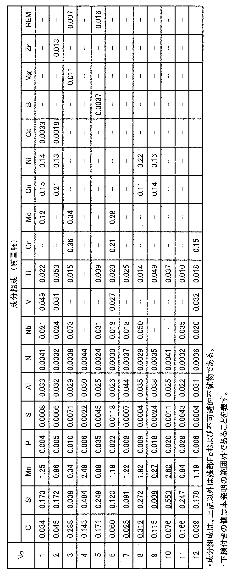
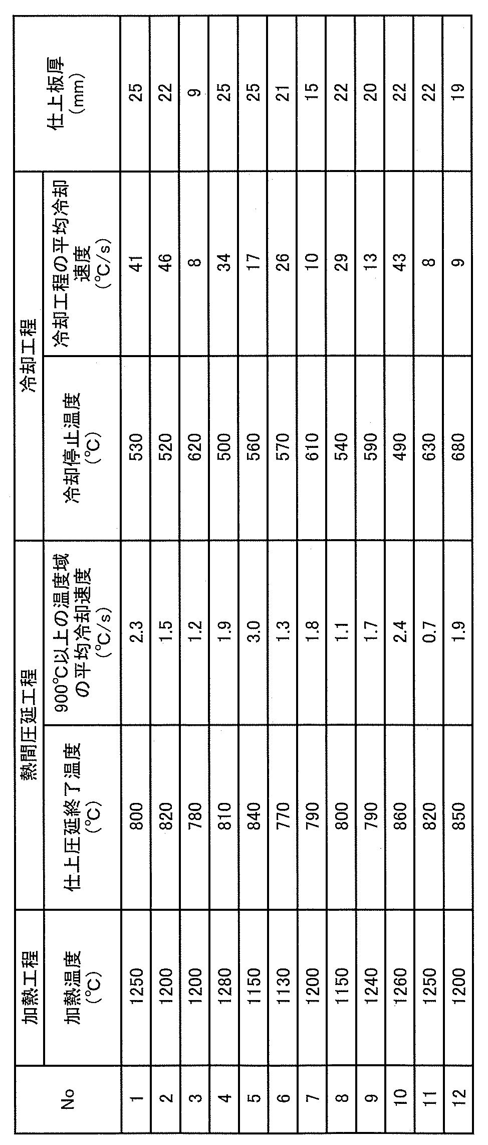
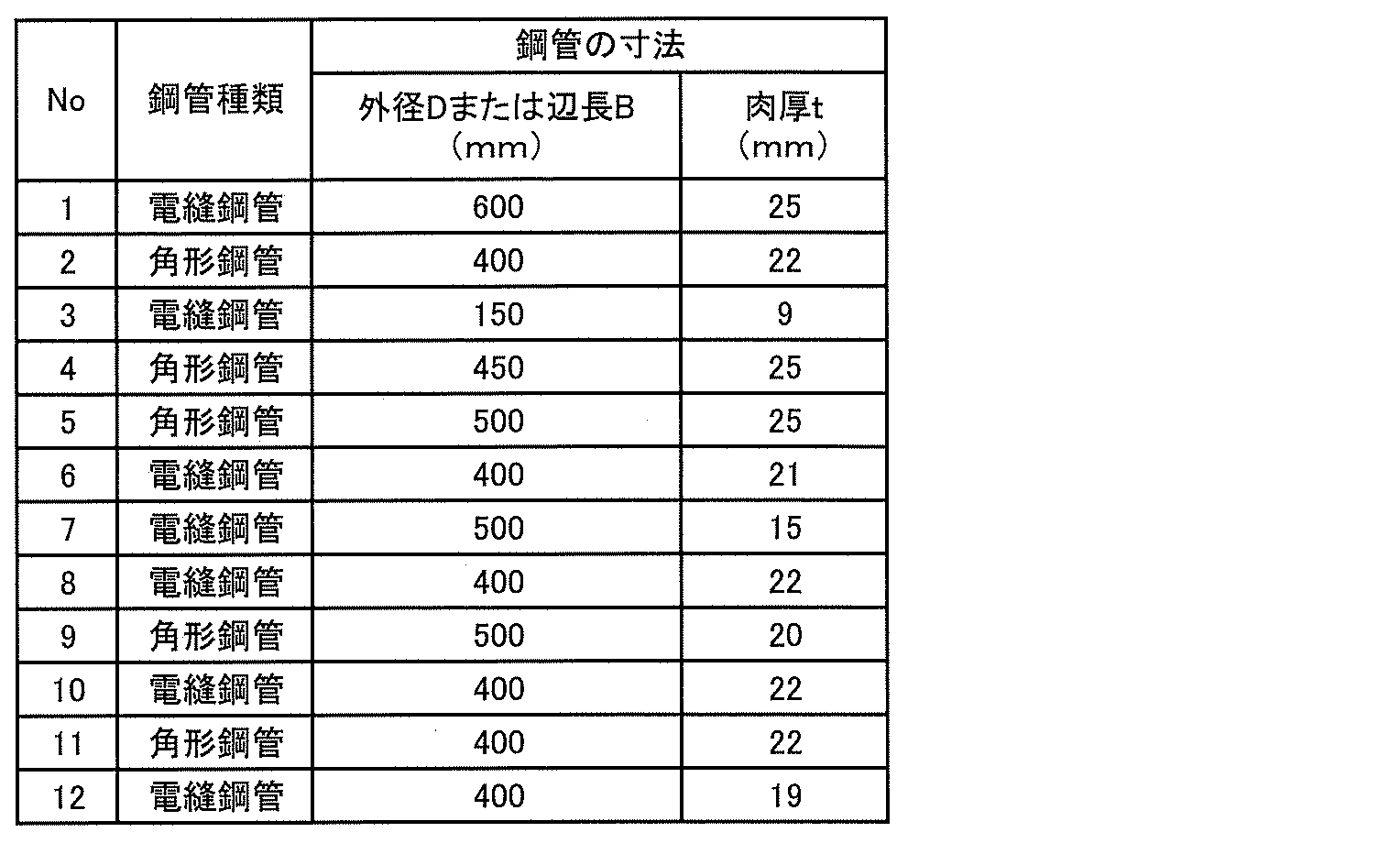
組織観察用の試験片は、観察面が熱間圧延時の圧延方向断面かつ板厚1/2t位置となるように採取し、研磨した後、ナイタール腐食して作製した。組織観察は、光学顕微鏡(倍率:1000倍)または走査型電子顕微鏡(SEM、倍率:1000倍)を用いて、鋼板の板厚1/2t位置における組織を観察し、撮像した。得られた光学顕微鏡像およびSEM像から、フェライト、ベイナイトおよび残部組織(パーライト、マルテンサイト、オーステナイト)の面積率を求めた。各組織の面積率は、5視野で観察を行い、各視野で得られた値の平均値として算出した。ここでは、組織観察により得られた面積率を、各組織の体積率とした。
引張方向が圧延方向と平行になるように、JIS5号の引張試験片を採取した。引張試験片は、熱延鋼板については幅方向端部から幅方向に1/4W(W:板幅)の位置から、電縫鋼管については電縫溶接部から周方向に90°離れた位置から、角形鋼管については電縫溶接部を含む平板部に隣接した平板部からそれぞれ採取した。引張試験は、JIS Z 2241(2011年)の規定に準拠して実施し、降伏応力σy、引張強度をそれぞれ測定して、(降伏応力σy)/(引張強度)で定義される降伏比を算出した。
相当塑性ひずみ分布は、SEM-DIC法により測定した。引張方向が圧延方向と平行になるように、熱延鋼板の板厚中央、電縫鋼管の肉厚中央、および角形鋼管の肉厚中央から、図1に示す引張試験片を採取した。熱延鋼板の板幅方向については、幅方向端部から幅方向に1/4W(W:板幅)、電縫鋼管の周方向については電縫溶接部から周方向に90°離れた位置、角形鋼管については電縫溶接部を含む平板部に隣接した平板部で採取を行った。得られた引張試験片の一方の面を研磨し、ナイタール腐食して、SEM(倍率:1000倍)を用いて平行部(引張変形部)を5視野撮像した。その後、引張速度5mm/minで、熱延鋼板から採取した試験片には8.0%の引張ひずみ、電縫鋼管および角形鋼管から採取した試験片には4.0%の引張ひずみをそれぞれ付与し、除荷した。その後、SEM(倍率:1000倍)を用いて引張前(引張ひずみ付与前)と同一の視野を撮像した。得られた引張前後のSEM像をもとに、画像解析ソフトGOM Correlate(GOM社)を用いて、DIC法により撮像面の相当塑性ひずみ分布を算出した。DIC法は、物体表面のランダムパターンを変形前後で比較することで、観察面の各所における変位やひずみを測定する手法である。具体的には、変形前画像においてサブセットと呼ばれる正方形領域を定義し、サブセット内部のランダムパターンをもとにサブセットを変形前後で追跡し、サブセット中央点の変位を算出する。この操作を画像全体で網羅的に行い変位分布およびひずみ分布を得る。本発明では、金属組織のナイタール腐食痕をランダムパターンとして利用し、1910ピクセル×2560ピクセルの画像に対し、サブセットサイズを80ピクセル×80ピクセル(3.6μm×3.6μm)、測定間隔を10ピクセル(0.45μm)とした。横軸を得られた相当塑性ひずみ(単位:無し)の自然対数、縦軸を割合(面積率)(単位:%)としたものを正規分布で近似し、このときの標準偏差を対数標準偏差(相当塑性ひずみ分布の対数標準偏差)とした。具体的には以下の方法により、対数標準偏差を求めた。まず、相当塑性ひずみが0~0.20の範囲内において、階級幅を0.02として各階級の割合(面積率)(単位:%)を求めた。このとき、相当塑性ひずみが0以上0.02未満の階級を1番目の階級、0.02以上0.04未満の階級を2番目の階級、・・・、0.18以上0.20未満の階級を10番目の階級とした。xiをi番目の階級の階級値の自然対数、x0を相当塑性ひずみの自然対数の平均値として、下記(4)式と(5)式により対数標準偏差を求めた。

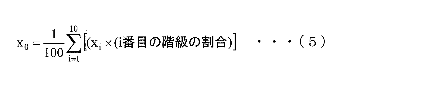
電縫鋼管および角形鋼管の両端に耐圧板を取り付け、大型圧縮試験装置により軸圧縮試験を実施した。圧縮荷重が最大になったときの応力を、最大応力度σmax(N/mm2)とした。また、前記引張試験により求めた降伏応力σyを用いて、耐力上昇率τ(=σmax/σy)を算出した。

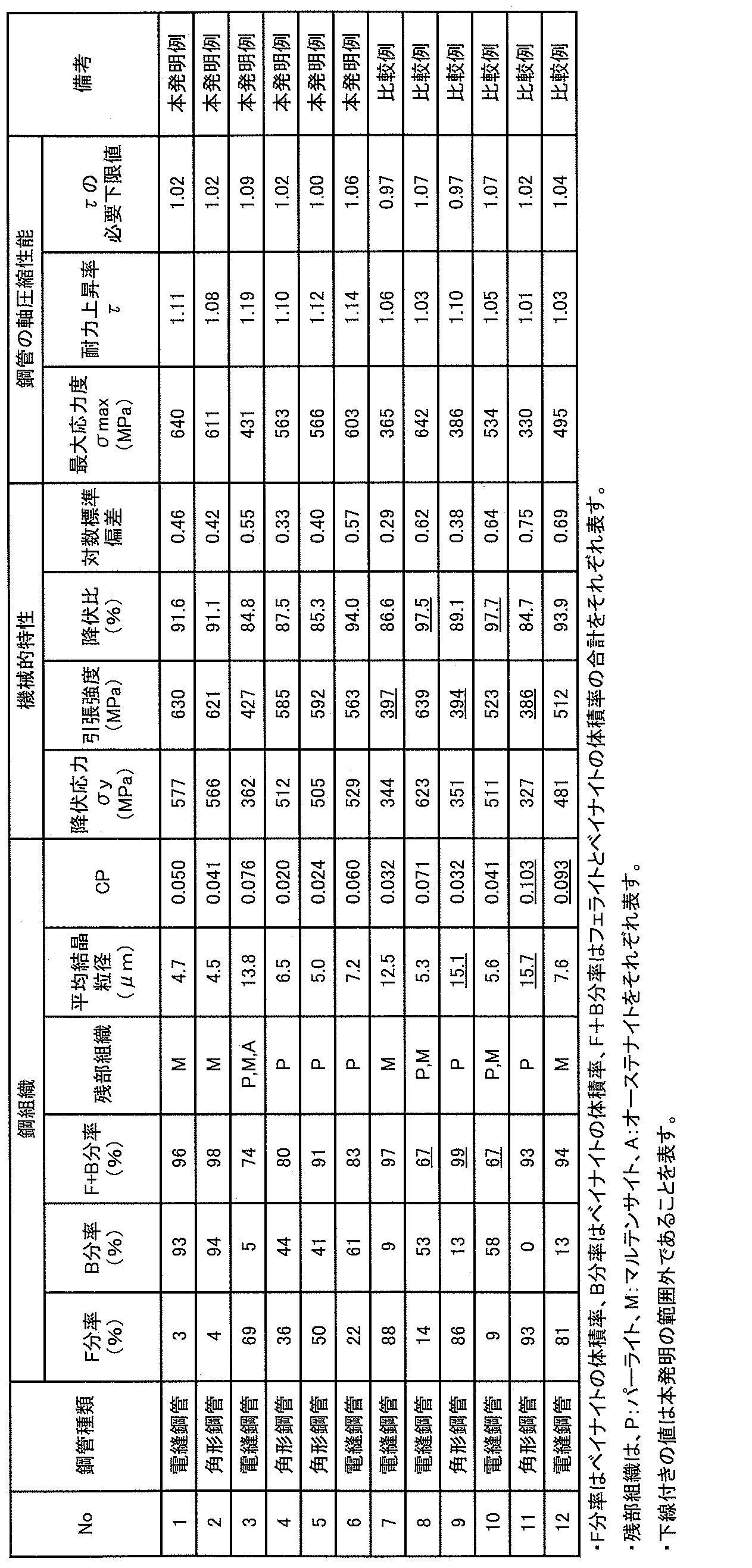
Claims (13)
- 成分組成は、質量%で、
C :0.030%以上0.300%以下、
Si:0.010%以上0.500%以下、
Mn:0.30%以上2.50%以下、
P :0.050%以下、
S :0.0200%以下、
Al:0.005%以上0.100%以下、
N :0.0100%以下
を含有し、残部がFeおよび不可避的不純物からなり、
板厚中央の鋼組織は、
体積率で、フェライトとベイナイトの合計が70%以上98%以下であり、
残部がパーライト、マルテンサイト、オーステナイトから選択される1種または2種以上からなり、
平均結晶粒径が15.0μm以下であり、
下記(1)式で求められるCPの値が0.090以下であり、
引張強度が400MPa以上であり、
降伏比が90%以下である、熱延鋼板。
CP=(粒径20μm未満の結晶粒を除いた領域における大角粒界の総長さ)/(大角粒界の総長さ) ・・・(1) - 前記成分組成に加えてさらに、質量%で、
Nb:0.100%以下、
V :0.100%以下、
Ti:0.150%以下、
Cr:0.50%以下、
Mo:0.50%以下、
Cu:0.50%以下、
Ni:0.50%以下、
Ca:0.0050%以下、
B :0.0050%以下、
Mg:0.020%以下、
Zr:0.020%以下、
REM:0.020%以下、
のうちから選ばれた1種または2種以上を含む、請求項1に記載の熱延鋼板。 - 8.0%引張ひずみを付与した後の相当塑性ひずみ分布の対数標準偏差が0.70以下である、請求項1または2に記載の熱延鋼板。
- 母材部と電縫溶接部を有する電縫鋼管であって、
成分組成は、質量%で、
C :0.030%以上0.300%以下、
Si:0.010%以上0.500%以下、
Mn:0.30%以上2.50%以下、
P :0.050%以下、
S :0.0200%以下、
Al:0.005%以上0.100%以下、
N :0.0100%以下
を含有し、残部がFeおよび不可避的不純物からなり、
肉厚中央の鋼組織は、
体積率で、フェライトとベイナイトの合計が70%以上98%以下であり、
残部がパーライト、マルテンサイト、オーステナイトから選択される1種または2種以上からなり、
平均結晶粒径が15.0μm以下であり、
下記(1)式で求められるCPの値が0.090以下であり、
母材部の引張強度が400MPa以上であり、
母材部の降伏比が97%以下である、電縫鋼管。
CP=(粒径20μm未満の結晶粒を除いた領域における大角粒界の総長さ)/(大角粒界の総長さ) ・・・(1) - 前記成分組成に加えてさらに、質量%で、
Nb:0.100%以下、
V :0.100%以下、
Ti:0.150%以下、
Cr:0.50%以下、
Mo:0.50%以下、
Cu:0.50%以下、
Ni:0.50%以下、
Ca:0.0050%以下、
B :0.0050%以下、
Mg:0.020%以下、
Zr:0.020%以下、
REM:0.020%以下、
のうちから選ばれた1種または2種以上を含む、請求項4に記載の電縫鋼管。 - 母材部において4.0%引張ひずみを付与した後の相当塑性ひずみ分布の対数標準偏差が0.60以下である、請求項4または5に記載の電縫鋼管。
- 請求項4または5に記載の電縫鋼管が使用されている、ラインパイプ。
- 請求項6に記載の電縫鋼管が使用されている、ラインパイプ。
- 平板部と角部を有する角形鋼管であって、
成分組成は、質量%で、
C :0.030%以上0.300%以下、
Si:0.010%以上0.500%以下、
Mn:0.30%以上2.50%以下、
P :0.050%以下、
S :0.0200%以下、
Al:0.005%以上0.100%以下、
N :0.0100%以下
を含有し、残部がFeおよび不可避的不純物からなり、
肉厚中央の鋼組織は、
体積率で、フェライトとベイナイトの合計が70%以上98%以下であり、
残部がパーライト、マルテンサイト、オーステナイトから選択される1種または2種以上からなり、
平均結晶粒径が15.0μm以下であり、
下記(1)式で求められるCPの値が0.090以下であり、
平板部の引張強度が400MPa以上であり、
平板部の降伏比が97%以下である、角形鋼管。
CP=(粒径20μm未満の結晶粒を除いた領域における大角粒界の総長さ)/(大角粒界の総長さ) ・・・(1) - 前記成分組成に加えてさらに、質量%で、
Nb:0.100%以下、
V :0.100%以下、
Ti:0.150%以下、
Cr:0.50%以下、
Mo:0.50%以下、
Cu:0.50%以下、
Ni:0.50%以下、
Ca:0.0050%以下、
B :0.0050%以下、
Mg:0.020%以下、
Zr:0.020%以下、
REM:0.020%以下、
のうちから選ばれた1種または2種以上を含む、請求項9に記載の角形鋼管。 - 平板部において4.0%引張ひずみを付与した後の相当塑性ひずみ分布の対数標準偏差が0.60以下である、請求項9または10に記載の角形鋼管。
- 請求項9または10に記載の角形鋼管が、柱材として使用されている、建築構造物。
- 請求項11に記載の角形鋼管が、柱材として使用されている、建築構造物。
Priority Applications (4)
| Application Number | Priority Date | Filing Date | Title |
|---|---|---|---|
| CN202380074461.0A CN120019171A (zh) | 2022-11-08 | 2023-07-26 | 热轧钢板、电阻焊钢管和角形钢管以及管线管和建筑结构物 |
| KR1020257013098A KR20250075639A (ko) | 2022-11-08 | 2023-07-26 | 열연 강판, 전봉 강관 및 각형 강관 그리고 라인 파이프 및 건축 구조물 |
| EP23888294.8A EP4585705A4 (en) | 2022-11-08 | 2023-07-26 | HOT-ROLL-ROLL STEEL SHEET, ELECTRICALLY WELDED STEEL PIPE, RECTANGULAR STEEL PIPE, PIPING PIPE AND BUILDING STRUCTURE |
| JP2023566644A JP7700876B2 (ja) | 2022-11-08 | 2023-07-26 | 熱延鋼板、電縫鋼管および角形鋼管ならびにラインパイプおよび建築構造物 |
Applications Claiming Priority (2)
| Application Number | Priority Date | Filing Date | Title |
|---|---|---|---|
| JP2022178662 | 2022-11-08 | ||
| JP2022-178662 | 2022-11-08 |
Publications (1)
| Publication Number | Publication Date |
|---|---|
| WO2024100939A1 true WO2024100939A1 (ja) | 2024-05-16 |
Family
ID=91032114
Family Applications (1)
| Application Number | Title | Priority Date | Filing Date |
|---|---|---|---|
| PCT/JP2023/027298 Ceased WO2024100939A1 (ja) | 2022-11-08 | 2023-07-26 | 熱延鋼板、電縫鋼管および角形鋼管ならびにラインパイプおよび建築構造物 |
Country Status (6)
| Country | Link |
|---|---|
| EP (1) | EP4585705A4 (ja) |
| JP (1) | JP7700876B2 (ja) |
| KR (1) | KR20250075639A (ja) |
| CN (1) | CN120019171A (ja) |
| TW (1) | TWI863484B (ja) |
| WO (1) | WO2024100939A1 (ja) |
Citations (8)
| Publication number | Priority date | Publication date | Assignee | Title |
|---|---|---|---|---|
| JPH07224351A (ja) | 1994-02-14 | 1995-08-22 | Japan Casting & Forging Corp | 冷間加工後の一様伸びの優れた高強度熱延鋼板およびその製造方法 |
| JP2004330222A (ja) | 2003-05-02 | 2004-11-25 | Nakajima Steel Pipe Co Ltd | 角形鋼管および角形鋼管の製造方法 |
| JP5589885B2 (ja) | 2010-11-30 | 2014-09-17 | Jfeスチール株式会社 | 建築構造部材向け角形鋼管用厚肉熱延鋼板およびその製造方法 |
| JP6052374B2 (ja) | 2011-03-30 | 2016-12-27 | 新日鐵住金株式会社 | ラインパイプ用電縫鋼管及びその製造方法 |
| KR20200073343A (ko) * | 2018-12-13 | 2020-06-24 | 주식회사 포스코 | 용접이음부의 충격인성이 우수한 강재 및 이의 제조방법, 이를 이용한 강관 |
| WO2021100534A1 (ja) * | 2019-11-20 | 2021-05-27 | Jfeスチール株式会社 | 電縫鋼管用熱延鋼板およびその製造方法、電縫鋼管およびその製造方法、ラインパイプ、建築構造物 |
| JP7031477B2 (ja) | 2018-05-08 | 2022-03-08 | 日本製鉄株式会社 | 熱延鋼板、角形鋼管、およびその製造方法 |
| WO2022075026A1 (ja) * | 2020-10-05 | 2022-04-14 | Jfeスチール株式会社 | 角形鋼管およびその製造方法並びに建築構造物 |
Family Cites Families (7)
| Publication number | Priority date | Publication date | Assignee | Title |
|---|---|---|---|---|
| JP2007224351A (ja) | 2006-02-22 | 2007-09-06 | Sanyo Electric Co Ltd | 電解用電極及びその製造方法及びそれを用いた電解方法 |
| TWI646219B (zh) * | 2017-07-31 | 2019-01-01 | 日商新日鐵住金股份有限公司 | Hot-dip galvanized steel sheet |
| JP6693607B1 (ja) * | 2018-08-23 | 2020-05-13 | Jfeスチール株式会社 | 熱延鋼板およびその製造方法 |
| CN112601831B (zh) * | 2018-08-23 | 2022-05-31 | 杰富意钢铁株式会社 | 方形钢管及其制造方法以及建筑构造物 |
| KR102727370B1 (ko) * | 2019-04-08 | 2024-11-07 | 제이에프이 스틸 가부시키가이샤 | 각형 강관 및 그의 제조 방법 그리고 건축 구조물 |
| US12565697B2 (en) * | 2020-04-02 | 2026-03-03 | Jfe Steel Corporation | Electric resistance welded steel pipe and method for producing the same |
| KR20220084651A (ko) * | 2020-12-14 | 2022-06-21 | 주식회사 포스코 | 굽힘성 및 성형성이 우수한 고강도 강판 및 이의 제조방법 |
-
2023
- 2023-07-26 KR KR1020257013098A patent/KR20250075639A/ko active Pending
- 2023-07-26 JP JP2023566644A patent/JP7700876B2/ja active Active
- 2023-07-26 EP EP23888294.8A patent/EP4585705A4/en active Pending
- 2023-07-26 WO PCT/JP2023/027298 patent/WO2024100939A1/ja not_active Ceased
- 2023-07-26 CN CN202380074461.0A patent/CN120019171A/zh active Pending
- 2023-08-04 TW TW112129346A patent/TWI863484B/zh active
Patent Citations (8)
| Publication number | Priority date | Publication date | Assignee | Title |
|---|---|---|---|---|
| JPH07224351A (ja) | 1994-02-14 | 1995-08-22 | Japan Casting & Forging Corp | 冷間加工後の一様伸びの優れた高強度熱延鋼板およびその製造方法 |
| JP2004330222A (ja) | 2003-05-02 | 2004-11-25 | Nakajima Steel Pipe Co Ltd | 角形鋼管および角形鋼管の製造方法 |
| JP5589885B2 (ja) | 2010-11-30 | 2014-09-17 | Jfeスチール株式会社 | 建築構造部材向け角形鋼管用厚肉熱延鋼板およびその製造方法 |
| JP6052374B2 (ja) | 2011-03-30 | 2016-12-27 | 新日鐵住金株式会社 | ラインパイプ用電縫鋼管及びその製造方法 |
| JP7031477B2 (ja) | 2018-05-08 | 2022-03-08 | 日本製鉄株式会社 | 熱延鋼板、角形鋼管、およびその製造方法 |
| KR20200073343A (ko) * | 2018-12-13 | 2020-06-24 | 주식회사 포스코 | 용접이음부의 충격인성이 우수한 강재 및 이의 제조방법, 이를 이용한 강관 |
| WO2021100534A1 (ja) * | 2019-11-20 | 2021-05-27 | Jfeスチール株式会社 | 電縫鋼管用熱延鋼板およびその製造方法、電縫鋼管およびその製造方法、ラインパイプ、建築構造物 |
| WO2022075026A1 (ja) * | 2020-10-05 | 2022-04-14 | Jfeスチール株式会社 | 角形鋼管およびその製造方法並びに建築構造物 |
Non-Patent Citations (1)
| Title |
|---|
| See also references of EP4585705A4 |
Also Published As
| Publication number | Publication date |
|---|---|
| KR20250075639A (ko) | 2025-05-28 |
| JPWO2024100939A1 (ja) | 2024-05-16 |
| TWI863484B (zh) | 2024-11-21 |
| TW202419639A (zh) | 2024-05-16 |
| CN120019171A (zh) | 2025-05-16 |
| EP4585705A4 (en) | 2025-12-31 |
| JP7700876B2 (ja) | 2025-07-01 |
| EP4585705A1 (en) | 2025-07-16 |
Similar Documents
| Publication | Publication Date | Title |
|---|---|---|
| JP6874913B2 (ja) | 角形鋼管およびその製造方法ならびに建築構造物 | |
| TWI762881B (zh) | 電焊鋼管及其製造方法以及鋼管樁 | |
| US12553544B2 (en) | Electric resistance welded steel pipe, method for producing the same, line pipe, and building structure | |
| JP7563585B2 (ja) | 電縫鋼管およびその製造方法 | |
| CN113453817B (zh) | 方形钢管、其制造方法以及建筑结构物 | |
| TW202014531A (zh) | 角形鋼管及其製造方法以及建築構造物 | |
| JP7529049B2 (ja) | 角形鋼管およびその製造方法、熱延鋼板およびその製造方法、並びに建築構造物 | |
| WO2020170775A1 (ja) | 角形鋼管およびその製造方法並びに建築構造物 | |
| JP2005002385A (ja) | 成形性と靱性に優れた鋼管とその製造方法 | |
| CN114729426B (zh) | 电阻焊钢管用热轧钢板及其制造方法、电阻焊钢管及其制造方法、管线管、建筑结构物 | |
| TWI738246B (zh) | 電焊鋼管及其製造方法以及鋼管樁 | |
| WO2024062686A1 (ja) | 熱延鋼板、角形鋼管およびそれらの製造方法並びに建築構造物 | |
| JP7276641B1 (ja) | 電縫鋼管およびその製造方法 | |
| JP7396552B1 (ja) | 熱延鋼板、角形鋼管およびそれらの製造方法並びに建築構造物 | |
| JP7424551B1 (ja) | 熱延鋼板、角形鋼管、それらの製造方法および建築構造物 | |
| JP7700876B2 (ja) | 熱延鋼板、電縫鋼管および角形鋼管ならびにラインパイプおよび建築構造物 | |
| JP7571918B1 (ja) | 角形鋼管およびその製造方法ならびに建築構造物 | |
| JP7635881B2 (ja) | 熱延鋼板および電縫鋼管 | |
| JP7848946B1 (ja) | 角形鋼管およびその製造方法ならびに建築構造物 | |
| CA3159223C (en) | Electric resistance welded steel pipe, method for producing the same, line pipe, and building structure | |
| WO2023210046A1 (ja) | 電縫鋼管およびその製造方法 | |
| KR20250034979A (ko) | 전봉 강관 및 그의 제조 방법 |
Legal Events
| Date | Code | Title | Description |
|---|---|---|---|
| WWE | Wipo information: entry into national phase |
Ref document number: 2023566644 Country of ref document: JP |
|
| 121 | Ep: the epo has been informed by wipo that ep was designated in this application |
Ref document number: 23888294 Country of ref document: EP Kind code of ref document: A1 |
|
| WWE | Wipo information: entry into national phase |
Ref document number: 2023888294 Country of ref document: EP |
|
| ENP | Entry into the national phase |
Ref document number: 2023888294 Country of ref document: EP Effective date: 20250411 |
|
| ENP | Entry into the national phase |
Ref document number: 20257013098 Country of ref document: KR Kind code of ref document: A |
|
| WWE | Wipo information: entry into national phase |
Ref document number: 1020257013098 Country of ref document: KR |
|
| WWE | Wipo information: entry into national phase |
Ref document number: 202380074461.0 Country of ref document: CN |
|
| WWP | Wipo information: published in national office |
Ref document number: 202380074461.0 Country of ref document: CN |
|
| NENP | Non-entry into the national phase |
Ref country code: DE |
|
| WWP | Wipo information: published in national office |
Ref document number: 2023888294 Country of ref document: EP |