WO2024106377A1 - モータ制御装置 - Google Patents
モータ制御装置 Download PDFInfo
- Publication number
- WO2024106377A1 WO2024106377A1 PCT/JP2023/040764 JP2023040764W WO2024106377A1 WO 2024106377 A1 WO2024106377 A1 WO 2024106377A1 JP 2023040764 W JP2023040764 W JP 2023040764W WO 2024106377 A1 WO2024106377 A1 WO 2024106377A1
- Authority
- WO
- WIPO (PCT)
- Prior art keywords
- command value
- equation
- cmd
- reaction force
- motion
- Prior art date
- Legal status (The legal status is an assumption and is not a legal conclusion. Google has not performed a legal analysis and makes no representation as to the accuracy of the status listed.)
- Ceased
Links
Images








Classifications
-
- B—PERFORMING OPERATIONS; TRANSPORTING
- B62—LAND VEHICLES FOR TRAVELLING OTHERWISE THAN ON RAILS
- B62D—MOTOR VEHICLES; TRAILERS
- B62D15/00—Steering not otherwise provided for
- B62D15/02—Steering position indicators ; Steering position determination; Steering aids
- B62D15/025—Active steering aids, e.g. helping the driver by actively influencing the steering system after environment evaluation
-
- B—PERFORMING OPERATIONS; TRANSPORTING
- B62—LAND VEHICLES FOR TRAVELLING OTHERWISE THAN ON RAILS
- B62D—MOTOR VEHICLES; TRAILERS
- B62D5/00—Power-assisted or power-driven steering
- B62D5/04—Power-assisted or power-driven steering electrical, e.g. using an electric servo-motor connected to, or forming part of, the steering gear
- B62D5/0457—Power-assisted or power-driven steering electrical, e.g. using an electric servo-motor connected to, or forming part of, the steering gear characterised by control features of the drive means as such
- B62D5/046—Controlling the motor
- B62D5/0463—Controlling the motor calculating assisting torque from the motor based on driver input
-
- B—PERFORMING OPERATIONS; TRANSPORTING
- B62—LAND VEHICLES FOR TRAVELLING OTHERWISE THAN ON RAILS
- B62D—MOTOR VEHICLES; TRAILERS
- B62D6/00—Arrangements for automatically controlling steering depending on driving conditions sensed and responded to, e.g. control circuits
- B62D6/002—Arrangements for automatically controlling steering depending on driving conditions sensed and responded to, e.g. control circuits computing target steering angles for front or rear wheels
-
- H—ELECTRICITY
- H02—GENERATION; CONVERSION OR DISTRIBUTION OF ELECTRIC POWER
- H02P—CONTROL OR REGULATION OF ELECTRIC MOTORS, ELECTRIC GENERATORS OR DYNAMO-ELECTRIC CONVERTERS; CONTROLLING TRANSFORMERS, REACTORS OR CHOKE COILS
- H02P23/00—Arrangements or methods for the control of AC motors characterised by a control method other than vector control
- H02P23/12—Observer control, e.g. using Luenberger observers or Kalman filters
-
- H—ELECTRICITY
- H02—GENERATION; CONVERSION OR DISTRIBUTION OF ELECTRIC POWER
- H02P—CONTROL OR REGULATION OF ELECTRIC MOTORS, ELECTRIC GENERATORS OR DYNAMO-ELECTRIC CONVERTERS; CONTROLLING TRANSFORMERS, REACTORS OR CHOKE COILS
- H02P23/00—Arrangements or methods for the control of AC motors characterised by a control method other than vector control
- H02P23/14—Estimation or adaptation of motor parameters, e.g. rotor time constant, flux, speed, current or voltage
-
- H—ELECTRICITY
- H02—GENERATION; CONVERSION OR DISTRIBUTION OF ELECTRIC POWER
- H02P—CONTROL OR REGULATION OF ELECTRIC MOTORS, ELECTRIC GENERATORS OR DYNAMO-ELECTRIC CONVERTERS; CONTROLLING TRANSFORMERS, REACTORS OR CHOKE COILS
- H02P29/00—Arrangements for regulating or controlling electric motors, appropriate for both AC and DC motors
- H02P29/40—Regulating or controlling the amount of current drawn or delivered by the motor for controlling the mechanical load
-
- H—ELECTRICITY
- H02—GENERATION; CONVERSION OR DISTRIBUTION OF ELECTRIC POWER
- H02P—CONTROL OR REGULATION OF ELECTRIC MOTORS, ELECTRIC GENERATORS OR DYNAMO-ELECTRIC CONVERTERS; CONTROLLING TRANSFORMERS, REACTORS OR CHOKE COILS
- H02P2205/00—Indexing scheme relating to controlling arrangements characterised by the control loops
- H02P2205/01—Current loop, i.e. comparison of the motor current with a current reference
-
- H—ELECTRICITY
- H02—GENERATION; CONVERSION OR DISTRIBUTION OF ELECTRIC POWER
- H02P—CONTROL OR REGULATION OF ELECTRIC MOTORS, ELECTRIC GENERATORS OR DYNAMO-ELECTRIC CONVERTERS; CONTROLLING TRANSFORMERS, REACTORS OR CHOKE COILS
- H02P27/00—Arrangements or methods for the control of AC motors characterised by the kind of supply voltage
- H02P27/04—Arrangements or methods for the control of AC motors characterised by the kind of supply voltage using variable-frequency supply voltage, e.g. inverter or converter supply voltage
- H02P27/06—Arrangements or methods for the control of AC motors characterised by the kind of supply voltage using variable-frequency supply voltage, e.g. inverter or converter supply voltage using DC to AC converters or inverters
- H02P27/08—Arrangements or methods for the control of AC motors characterised by the kind of supply voltage using variable-frequency supply voltage, e.g. inverter or converter supply voltage using DC to AC converters or inverters with pulse width modulation
Definitions
- This invention relates to a motor control device that drives and controls an electric motor for steering angle control.
- Patent Document 1 discloses that the control gain (control amount) is changed according to the lateral displacement of the vehicle from the center of the driving lane, the yaw angle of the vehicle relative to the driving lane, etc. Specifically, when the yaw angle is an angle where the vehicle is heading toward the deviation side, the control gain is increased, and when the yaw angle is an angle where the vehicle is heading toward the deviation avoidance side, the control gain is decreased.
- the objective of one embodiment of the present invention is to provide a motor control device that can provide a steering reaction force to the driver in a new way when in driving assistance mode.
- One embodiment of the present invention provides a motor control device for driving and controlling an electric motor of a steering device, the motor control device including: a manual steering command value generation unit that generates a manual steering command value using the equation of motion of a reference model of the steering device; an integrated angle command value calculation unit that calculates an integrated angle command value by adding the manual steering command value to an automatic steering command value given in a driving assistance mode; a control unit that controls the angle of an electric motor for steering angle control based on the integrated angle command value; and a motion equation setting unit that changes the motion equation according to the time differential value of the angle deviation between the automatic steering command value and the actual steering angle.
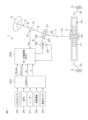
- FIG. 1 is a schematic diagram showing a schematic configuration of an electric power steering system to which a motor control device according to a first embodiment of the present invention is applied.
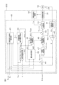
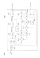
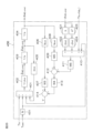
- FIG. 2 is a block diagram showing the electrical configuration of the motor control ECU.
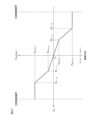
- FIG. 3 is a graph showing an example of setting the assist torque command value T asst relative to the torsion bar torque T tb .
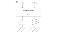
- FIG. 4 is a schematic diagram showing an example of a reference EPS model used in the manual steering command value generating unit.
- FIG. 5 is a block diagram showing the configuration of the angle control unit.
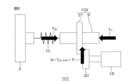
- FIG. 6 is a schematic diagram showing an example of the configuration of a physical model of an electric power steering system.
- FIG. 7 is a block diagram showing the configuration of the disturbance torque estimating unit.
- FIG. 1 is a schematic diagram showing a schematic configuration of an electric power steering system to which a motor control device according to a first embodiment of the present invention is applied.
- FIG. 2 is a block diagram showing the electrical configuration of the motor
- FIG. 8 is a schematic diagram showing the configuration of the torque control unit.
- FIG. 9 is a flowchart showing the procedure of the weight setting process performed by the weight setting unit in the driving assistance mode.
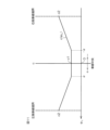
- FIG. 10 is a graph showing an example of setting the first virtual load spring stiffness coefficient kr(e L ) and the second virtual load spring stiffness coefficient kg with respect to the lateral deviation e L .
- FIG. 11 is a graph showing an example of setting the virtual load viscous damping coefficient c(e L ) relative to the lateral deviation e L .
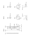
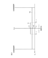
- FIG. 12A is a schematic diagram showing an example of the position of the vehicle when the vehicle reference position is to the right of the center of the lane, FIG.
- FIG. 12B is a schematic diagram showing an example of the angle deviation ⁇ when the actual steering angle ⁇ and the automatic steering command value ⁇ AD,cmd are both positive in sign and the actual steering angle ⁇ is larger than the automatic steering command value ⁇ AD , cmd
- FIG. 12C is a schematic diagram showing an example of the angle deviation ⁇ A ⁇ when the actual steering angle ⁇ has a negative sign and the automatic steering command value ⁇ AD,cmd has a positive sign.
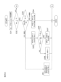
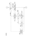
- FIG. 13 is a flowchart showing the procedure of the spring stiffness coefficient setting process performed by the road surface reaction force characteristic setting unit in the driving assistance mode.
- FIG. 14 is a graph showing an example of setting the first virtual load viscous damping coefficient cr(e L ) and the second virtual load viscous damping coefficient cg with respect to the lateral deviation e L .
- FIG. 15 is a flowchart showing the procedure of a road surface reaction force characteristic setting process performed by a road surface reaction force characteristic setting unit according to the first modified example in the driving assistance mode.
- FIG. 16 is a flowchart showing the procedure of a viscous damping coefficient setting process performed by a road surface reaction force characteristic setting unit according to the second modified example in the driving assistance mode.
- FIG. 17 is a flowchart showing the procedure of a road surface reaction force characteristic setting process performed by the road surface reaction force characteristic setting unit in the driving assistance mode in the third embodiment.
- FIG. 15 is a flowchart showing the procedure of a road surface reaction force characteristic setting process performed by a road surface reaction force characteristic setting unit according to the first modified example in the driving assistance mode.
- FIG. 16 is a flowchart showing the procedure
- FIG. 18 is a flowchart showing the procedure of a road surface reaction force characteristic setting process performed by the road surface reaction force characteristic setting unit in the driving assistance mode in the fourth embodiment.
- FIG. 19 is a block diagram showing a first modified example of the motor control ECU.
- FIG. 20 is a graph showing an example of setting the target virtual spring reaction force T tb,d (e L ) relative to the lateral deviation e L .
- FIG. 21 is a graph showing an example of setting the first virtual load spring stiffness coefficient kr and the second virtual load spring stiffness coefficient kg with respect to the lateral deviation eL .
- FIG. 22 is a graph showing an example of setting the first virtual load viscous damping coefficient cr(e L ) and the second virtual load viscous damping coefficient cg with respect to the lateral deviation e L .
- FIG. 23 is a schematic diagram showing an example of a reference EPS model used in the manual steering command value generating unit described in WO 2023/286169.
- FIG. 24 is a block diagram showing the configuration of a manual steering command value generating unit in a first modified example of the motor control ECU.
- FIG. 25A is a flowchart showing a part of the procedure of the coefficient/weight setting process performed by the equation of motion setting unit in the driving assistance mode.
- FIG. 25B is a flowchart showing part of the procedure of the coefficient/weight setting process performed by the equation of motion setting unit in the driving assistance mode.
- FIG. 26 is a block diagram showing the configuration of a manual steering command value generating unit in a second modified example of the motor control ECU.
- One embodiment of the present invention provides a motor control device for driving and controlling an electric motor of a steering device, the motor control device including: a manual steering command value generation unit that generates a manual steering command value using an equation of motion of a reference model of the steering device; an integrated angle command value calculation unit that calculates an integrated angle command value by adding the manual steering command value to an automatic steering command value given in a driving assistance mode; a control unit that controls the angle of an electric motor for steering angle control based on the integrated angle command value; and a motion equation setting unit that changes the motion equation in accordance with a time differential value of the angle deviation between the automatic steering command value and an actual steering angle.
- the equation of motion includes a road reaction force characteristic coefficient
- the equation of motion setting unit changes the equation of motion by changing the value of at least one of the road reaction force characteristic coefficients included in the equation of motion.
- the equation of motion setting unit is configured to change the equation of motion by switching between a first equation of motion and a second equation of motion, and in the first equation of motion, a target virtual spring reaction force corresponding to the lateral position of the vehicle reference position relative to the driving lane is used as the virtual spring reaction force, and in the second equation of motion, a virtual spring reaction force that is set using a constant virtual load spring stiffness coefficient regardless of the lateral position is used as the virtual spring reaction force.
- the equation of motion setting unit is configured to determine whether the vehicle is heading toward the departure side or toward the departure avoidance side based on either the lateral position of the vehicle reference position with respect to the driving lane or the angular deviation, and the time differential value, and to change the equation of motion based on the determination result.
- the equation of motion setting unit determines whether the vehicle is heading toward the departure side or toward the departure avoidance side based on either the lateral position of the vehicle reference position relative to the driving lane or the angular deviation, and the time differential value, and when the vehicle is heading toward the departure avoidance side, the value of at least one of the road reaction force characteristic coefficients included in the equation of motion is made smaller than when the vehicle is heading toward the departure side.
- the equation of motion setting unit determines whether the vehicle is heading toward the departure side or toward the departure avoidance side based on the time differential value and either one of the lateral position of the vehicle reference position with respect to the driving lane and the angular deviation, and when the vehicle is heading toward the departure side, changes at least one of the road reaction force characteristic coefficients included in the equation of motion according to the lateral position.
- the equation of motion setting unit uses the time differential value to determine whether the vehicle is heading toward the departure side or toward the departure avoidance side, and when the vehicle is heading toward the departure side, sets the first equation of motion as the equation of motion, and when the vehicle is heading toward the departure avoidance side, sets the second equation of motion as the equation of motion.
- FIG. 1 is a schematic diagram showing the general configuration of an electric power steering system to which a steering device according to a first embodiment of the present invention is applied.
- the electric power steering system 1 includes a steering wheel (handle) 2 as a steering member for steering the vehicle, a steering mechanism 4 that steers the steered wheels 3 in conjunction with the rotation of the steering wheel 2, and a steering assist mechanism 5 that assists the driver in steering.
- the steering wheel 2 and the steering mechanism 4 are mechanically connected via a steering shaft 6 and an intermediate shaft 7.
- the steering shaft 6 includes an input shaft 8 connected to the steering wheel 2 and an output shaft 9 connected to the intermediate shaft 7.
- the input shaft 8 and the output shaft 9 are connected via a torsion bar 10 so as to be capable of relative rotation.
- a torque sensor 12 is disposed near the torsion bar 10.
- the torque sensor 12 detects a torsion bar torque Ttb applied to the steering wheel 2 based on the amount of relative rotational displacement between the input shaft 8 and the output shaft 9.
- the torsion bar torque Ttb detected by the torque sensor 12 is detected as a positive value for torque for steering leftward and a negative value for torque for steering rightward, and the magnitude of the torsion bar torque Ttb increases as the absolute value increases.
- the torsion bar torque Ttb is an example of the "steering torque" of the present invention.
- the steering mechanism 4 is made up of a rack-and-pinion mechanism including a pinion shaft 13 and a rack shaft 14 as a steering shaft.
- the steered wheels 3 are connected to each end of the rack shaft 14 via tie rods 15 and knuckle arms (not shown).
- the pinion shaft 13 is connected to the intermediate shaft 7.
- the pinion shaft 13 rotates in conjunction with the steering of the steering wheel 2.
- a pinion 16 is connected to the tip of the pinion shaft 13.
- the rack shaft 14 extends linearly in the left-right direction of the vehicle.
- a rack 17 that meshes with the pinion 16 is formed in the middle of the rack shaft 14 in the axial direction.
- the pinion 16 and rack 17 convert the rotation of the pinion shaft 13 into axial movement of the rack shaft 14.
- the steered wheels 3 can be steered by moving the rack shaft 14 in the axial direction.
- the steering assist mechanism 5 includes an electric motor 18 for generating a steering assist force (assist torque) and a reducer 19 for amplifying the output torque of the electric motor 18 and transmitting it to the steering mechanism 4.
- the reducer 19 is made up of a worm gear mechanism including a worm gear 20 and a worm wheel 21 that meshes with the worm gear 20.
- the reducer 19 is housed in a gear housing 22 that serves as a transmission mechanism housing.
- the reduction ratio (gear ratio) of the reducer 19 may be represented as N.
- the reduction ratio N is defined as the ratio ( ⁇ wg / ⁇ WW ) of the worm gear angle ⁇ wg , which is the rotation angle of the worm gear 20, to the worm wheel angle ⁇ ww , which is the rotation angle of the worm wheel 21.
- the worm gear 20 is rotated by the electric motor 18.
- the worm wheel 21 is connected to the output shaft 9 so that they can rotate together.
- the worm gear 20 When the worm gear 20 is driven to rotate by the electric motor 18, the worm wheel 21 is driven to rotate, and motor torque is applied to the steering shaft 6, causing the steering shaft 6 (output shaft 9) to rotate. The rotation of the steering shaft 6 is then transmitted to the pinion shaft 13 via the intermediate shaft 7. The rotation of the pinion shaft 13 is converted into axial movement of the rack shaft 14. This causes the steered wheels 3 to be steered. In other words, by driving the worm gear 20 to rotate by the electric motor 18, steering assistance by the electric motor 18 and steering of the steered wheels 3 are possible.
- the electric motor 18 is provided with a rotation angle sensor 23 for detecting the rotation angle of the rotor of the electric motor 18.
- the torque applied to the output shaft 9 includes the motor torque from the electric motor 18 and a disturbance torque Tlc other than the motor torque.
- the disturbance torque Tlc other than the motor torque includes a torsion bar torque Ttb , a road load torque (road reaction torque) Trl , a friction torque Tf , etc.
- the torsion bar torque Ttb is a torque applied from the steering wheel 2 side to the output shaft 9 due to a force applied to the steering wheel 2 by the driver, a force generated by steering inertia, or the like.
- the road load torque Trl is a torque applied to the output shaft 9 from the steered wheels 3 via the rack shaft 14 due to the self-aligning torque generated in the tires, forces generated by the suspension and tire/wheel alignment, frictional forces of the rack and pinion mechanism, etc.
- the vehicle is equipped with a CCD (Charge Coupled Device) camera 25 that photographs the road ahead of the vehicle in the direction of travel, a GPS (Global Positioning System) 26 for detecting the vehicle's position, a radar 27 for detecting road shapes and obstacles, a map information memory 28 that stores map information, and a vehicle speed sensor 29.
- CCD Charge Coupled Device
- GPS Global Positioning System
- the CCD camera 25, GPS 26, radar 27, map information memory 28 and vehicle speed sensor 29 are connected to a host ECU (Electronic Control Unit) 201 for driving assistance control. Based on the information obtained by the CCD camera 25, GPS 26, radar 27 and vehicle speed sensor 29, as well as map information, the host ECU 201 performs surrounding environment recognition, vehicle position estimation, route planning, etc., and determines control target values for steering and drive actuators.
- ECU Electronic Control Unit
- the host ECU 201 sets an automatic steering command value ⁇ AD,cmd for driving assistance.
- the automatic steering command value ⁇ AD,cmd is a target value of the steering angle for driving the vehicle along the target driving line.
- the driving assistance is a lane keeping assist (LKA) to prevent the vehicle from deviating from the lane.
- the driving assistance may be a lane centering assist (LKA) that assists in steering so that the vehicle stays in the center of the lane.
- the driving assistance may include lane keeping assist (LKA) and lane centering assist (LKA), as in the modified example of the motor control ECU described below.
- the automatic steering command value ⁇ AD,cmd is represented by the amount of rotation (rotation angle) from the neutral position of the output shaft 9, with the amount of rotation from the neutral position in the left steering direction being represented as a positive value, and the amount of rotation from the neutral position in the right steering direction being represented as a negative value.
- the automatic steering command value ⁇ AD,cmd is set based on, for example, the vehicle speed, the lateral deviation from the target driving line (lane center line), and the yaw deviation of the vehicle from the target driving line.
- the process of setting such an automatic steering command value ⁇ AD,cmd is well known, and therefore a detailed description thereof will be omitted here.
- the host ECU 201 also outputs a mode signal S mode indicating whether the driving mode is a normal mode or a driving assistance mode, and a lateral deviation e L with respect to the target driving line.
- the lateral deviation e L is the distance from the target driving line to a reference position of the vehicle (hereinafter referred to as the "vehicle reference position").
- the vehicle reference position is set to a predetermined position in the center of the vehicle width.
- the lateral deviation eL is an example of the "lateral position of the vehicle reference position with respect to the driving lane" in the present invention.
- the mode signal S mode , the automatic steering command value ⁇ AD,cmd , the lateral deviation e L and the vehicle speed V are provided to the motor control ECU 202 via an in-vehicle network.
- the torsion bar torque T tb detected by the torque sensor 12 and the output signal of the rotation angle sensor 23 are input to the motor control ECU 202.
- the motor control ECU 202 controls the electric motor 18 based on these input signals and information provided by the host ECU 201.
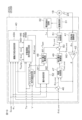
- FIG. 2 is a block diagram showing the electrical configuration of the motor control ECU 202.
- the motor control ECU 202 includes a microcomputer 40, a drive circuit (inverter circuit) 31 that is controlled by the microcomputer 40 and supplies power to the electric motor 18, and a current detection circuit 32 for detecting the current flowing through the electric motor 18 (hereinafter referred to as "motor current I m ").
- the microcomputer 40 is equipped with a CPU and memory (ROM, RAM, non-volatile memory, etc.), and functions as multiple functional processing units by executing a predetermined program.
- the multiple functional processing units include a rotation angle calculation unit 41, a reduction ratio division unit 42, a road surface reaction force characteristic setting unit 43, an assist torque command value setting unit 44, a manual steering command value generation unit 45, an integrated angle command value calculation unit 46, an angle control unit 47, a first weight multiplication unit 48, a second weight multiplication unit 49, an addition unit 50, a torque control unit (current control unit) 51, and a weight setting unit 52.
- the rotation angle calculation unit 41 calculates the rotor rotation angle ⁇ m of the electric motor 18 based on the output signal of the rotation angle sensor 23.
- the reduction ratio division unit 42 converts the rotor rotation angle ⁇ m into a rotation angle (actual steering angle) ⁇ of the output shaft 9 by dividing the rotor rotation angle ⁇ m by the reduction ratio N.
- the actual steering angle ⁇ is represented by the amount of rotation (rotation angle) from the neutral position of the output shaft 9, the amount of rotation from the neutral position in the left steering direction is represented as a positive value, and the amount of rotation from the neutral position in the right steering direction is represented as a negative value.
- the road reaction force characteristic setting unit 43 sets the virtual load spring stiffness coefficient k and the virtual load viscosity coefficient c used by the manual steering command value generating unit 45.
- the road reaction force characteristic setting unit 43 is an example of the "motion equation setting unit" in the present invention. The operation of the road reaction force characteristic setting unit 43 will be described in detail later.
- the assist torque command value setting unit 44 sets an assist torque command value T asst , which is a target value of the assist torque required for manual operation.
- the assist torque command value setting unit 44 sets the assist torque command value T asst based on the vehicle speed V provided by the host ECU 201 and the torsion bar torque T tb detected by the torque sensor 12.
- An example of setting the assist torque command value T asst relative to the torsion bar torque T tb is shown in FIG. 3.
- the assist torque command value T asst is set to a positive value when a steering assist force for steering leftward is to be generated from the electric motor 18, and is set to a negative value when a steering assist force for steering rightward is to be generated from the electric motor 18.
- the assist torque command value T asst is positive for a positive value of the torsion bar torque T tb , and is negative for a negative value of the torsion bar torque T tb .
- the assist torque command value T asst is set so that its absolute value increases as the absolute value of the torsion bar torque T tb increases, and is set so that its absolute value decreases as the vehicle speed V increases.
- the assist torque command value setting unit 44 may calculate the assist torque command value T asst by multiplying the torsion bar torque T tb by a preset constant.
- the manual steering command value generating unit 45 is provided to set a steering angle (more precisely, a rotation angle ⁇ of the output shaft 9) corresponding to the steering wheel operation as a manual steering command value ⁇ MD,cmd when the driver operates the steering wheel 2.
- the manual steering command value generating unit 45 generates the manual steering command value ⁇ MD,cmd using the torsion bar torque T tb detected by the torque sensor 12, the assist torque command value T asst set by the assist torque command value setting unit 44, and the virtual load spring stiffness coefficient k and the virtual load viscous damping coefficient c set by the road surface reaction force characteristic setting unit 43.
- the manual steering command value generating unit 45 will be described later in detail.
- the integrated angle command value calculation unit 46 adds the manual steering command value ⁇ MD,cmd to the automatic steering command value ⁇ AD,cmd set by the host ECU 201 to calculate an integrated angle command value ⁇ int,cmd .
- the angle control unit 47 calculates an integrated motor torque command value T mint,cmd based on the integrated angle command value ⁇ int ,cmd .
- the angle control unit 47 will be described in detail later.
- the first weight multiplier 48 multiplies the assist torque command value T asst set by the assist torque command value setting unit 44 by a first weight W1.
- the second weight multiplier 49 multiplies the integrated motor torque command value T mint,cmd by a second weight W2.
- the first weight W1 and the first weight W2 are set by a weight setting unit 52.
- the weight setting unit 52 will be described in detail later.
- the adder 50 calculates the motor torque command value Tm,cmd for the electric motor 18 by adding the assist torque command value W1 ⁇ T asst after multiplication by the first weight (after the first weighting process) and the integrated motor torque command value W2 ⁇ T mint, cmd after multiplication by the second weight (after the second weighting process).
- the torque control unit 51 drives the drive circuit 31 so that the motor torque of the electric motor 18 approaches the motor torque command value Tm ,cmd .
- the manual steering command value generating unit 45 sets the manual steering command value ⁇ MD,cmd by using a reference EPS model.
- Figure 4 is a schematic diagram showing an example of a reference EPS model used by the manual steering command value generating unit 45.
- the reference EPS model in Fig. 4 is an example of a "reference model for a steering device" in the present disclosure.
- This reference EPS model is a single inertia model including a lower column.
- the lower column corresponds to the output shaft 9 and the worm wheel 21.
- Jref is the inertia of the lower column
- Ttb is the torsion bar torque.
- the lower column is provided with a torsion bar torque Ttb , an assist torque N ⁇ T asst acting on the output shaft 9 from the electric motor 18, and a road load torque Trl .
- a virtual road load torque (virtual road reaction force) Trl is expressed by the following equation (1) using a virtual load spring stiffness coefficient k, a virtual load viscous damping coefficient c, and a manual steering command value ⁇ MD,cmd .
- J ref d 2 ⁇ MD,cmd /dt 2 T tb + N T ast - k ⁇ MD,cmd ⁇ c (d ⁇ MD, cmd / dt) ...
- the values of the virtual load spring stiffness coefficient k and the virtual load viscous damping coefficient c are set by the road reaction force characteristic setting unit 43.
- the virtual load spring stiffness coefficient k and the virtual load viscous damping coefficient c which are coefficients of the equation of motion of the formula (2), are an example of the "road reaction force characteristic coefficient" in the present invention.
- the manual steering command value generating unit 45 substitutes the torsion bar torque Ttb detected by the torque sensor 12 into Ttb and the assist torque command value T asst set by the assist torque command value setting unit 44 into T asst , and calculates the manual steering command value ⁇ MD,cmd by solving the differential equation of equation (2).
- FIG. 5 is a block diagram showing the configuration of the angle control unit 47.
- the angle control unit 47 calculates an integrated motor torque command value T mint,cmd based on the integrated angle command value ⁇ int,cmd .
- the angle control unit 47 includes a low pass filter (LPF) 61, a feedback control unit 62, a feedforward control unit 63, a disturbance torque estimating unit 64, a torque adding unit 65, a disturbance torque compensating unit 66, a reduction ratio dividing unit 67, and a reduction ratio multiplying unit 68.
- LPF low pass filter
- the reduction ratio multiplication unit 68 multiplies the motor torque command value Tm ,cmd calculated by the addition unit 50 (see FIG. 2) by the reduction ratio N of the reducer 19 to convert the motor torque command value Tm ,cmd into an output shaft torque command value N ⁇ Tm,cmd acting on the output shaft 9 (worm wheel 21).
- the low-pass filter 61 performs low-pass filtering on the integrated angle command value ⁇ int,cmd .
- the integrated angle command value ⁇ intL,cmd after the low-pass filtering is provided to the feedback control unit 62 and the feedforward control unit 63.
- the feedback control unit 62 is provided to bring the steering angle estimated value ⁇ calculated by the disturbance torque estimation unit 64 closer to the integrated angle command value ⁇ intL,cmd after low-pass filter processing.
- the feedback control unit 62 includes an angle deviation calculation unit 62A and a PD control unit 62B.
- the PD control unit 62B performs a PD calculation (proportional differential calculation) on the angle deviation ⁇ calculated by the angle deviation calculation unit 62A to calculate a feedback control torque Tfb .
- the feedback control torque Tfb is provided to a torque addition unit 65.
- the feedforward control unit 63 is provided to improve the control response by compensating for a delay in response due to the inertia of the electric power steering system 1.
- the feedforward control unit 63 includes an angular acceleration calculation unit 63A and an inertia multiplication unit 63B.
- the angular acceleration calculation unit 63A calculates a target angular acceleration d 2 ⁇ intL,cmd /dt 2 by second-order differentiation of the integrated angle command value ⁇ intL,cmd .
- the inertia J is obtained, for example, from a physical model (see FIG. 6 ) of the electric power steering system 1, which will be described later.
- the feedforward control torque T ff is provided to the torque addition unit 65 as an inertia compensation value.
- the torque addition unit 65 calculates a basic torque command value ( Tfb + Tff ) by adding the feedforward control torque Tff to the feedback control torque Tfb .
- the disturbance torque estimating unit 64 is provided to estimate a nonlinear torque (disturbance torque: torque other than motor torque) that occurs as a disturbance in the plant (the object to be controlled by the electric motor 18).
- the disturbance torque estimating unit 64 estimates the disturbance torque (disturbance load) T lc , the steering angle ⁇ , and the steering angle differential value (angular velocity) d ⁇ /dt based on the output shaft torque command value N ⁇ T m,cmd and the actual steering angle ⁇ .
- the estimated values of the disturbance torque T lc , the steering angle ⁇ , and the steering angle differential value (angular velocity) d ⁇ /dt are represented by ⁇ T lc , ⁇ , and d ⁇ /dt, respectively.
- the disturbance torque estimating unit 64 will be described in detail later.
- the disturbance torque estimated value ⁇ Tlc calculated by the disturbance torque estimating section 64 is provided as a disturbance torque compensation value to a disturbance torque compensating section 66.
- the steering angle estimated value ⁇ calculated by the disturbance torque estimating section 64 is provided to an angle deviation calculating section 62A.
- the integrated steering torque command value T sint,cmd is provided to a reduction ratio division unit 67.
- the reduction ratio division unit 67 calculates an integrated motor torque command value T mint,cmd by dividing the integrated steering torque command value T sint,cmd by the reduction ratio N.
- This integrated motor torque command value T mint,cmd is provided to a second weight multiplication unit 49 (see FIG. 2).
- the disturbance torque estimation unit 64 is composed of a disturbance observer that estimates the disturbance torque T lc , the steering angle ⁇ , and the angular velocity d ⁇ /dt by using, for example, a physical model 101 of the electric power steering system 1 shown in FIG.
- This physical model 101 includes a plant (an example of a motor-driven object) 102 that includes an output shaft 9 and a worm wheel 21 fixed to the output shaft 9.
- a torsion bar torque Ttb is applied to the plant 102 from the steering wheel 2 via the torsion bar 10, and a road load torque Trl is applied from the steered wheels 3 side.
- an output shaft torque command value N ⁇ T m,cmd is applied to the plant 102 via the worm gear 20 , and a friction torque T f is applied due to friction between the worm wheel 21 and the worm gear 20 .
- Tlc indicates a disturbance torque other than the motor torque applied to the plant 102.
- the disturbance torque Tlc is shown as the sum of the torsion bar torque Ttb , the road load torque Trl , and the friction torque Tf , but in reality, the disturbance torque Tlc includes torques other than these.
- x is a state variable vector
- u1 is a known input vector
- u2 is an unknown input vector
- y is an output vector (measurement value).
- A is a system matrix
- B1 is a first input matrix
- B2 is a second input matrix
- C is an output matrix
- D is a direct feedthrough matrix.
- the state equation is expanded to a system including the unknown input vector u2 as one of the states.
- the state equation of the expanded system (expanded state equation) is expressed by the following equation (5).
- x e is a state variable vector of the extended system, and is expressed by the following formula (6).
- a e is the system matrix of the extended system
- B e is the known input matrix of the extended system
- C e is the output matrix of the extended system.
- ⁇ xe represents an estimated value of xe .
- L is the observer gain.
- ⁇ y represents an estimated value of y.
- ⁇ xe is expressed by the following equation (8).
- ⁇ is an estimate of ⁇
- ⁇ T lc is an estimate of T lc .
- the disturbance torque estimation unit 64 calculates the state variable vector ⁇ x e based on the above equation (7).
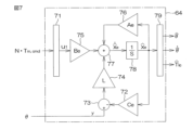
- FIG. 7 is a block diagram showing the configuration of the disturbance torque estimation unit 64.
- the disturbance torque estimation unit 64 includes an input vector input unit 71, an output matrix multiplication unit 72, a first adder unit 73, a gain multiplication unit 74, an input matrix multiplication unit 75, a system matrix multiplication unit 76, a second adder unit 77, an integrator unit 78, and a state variable vector output unit 79.
- the output shaft torque command value N ⁇ T m,cmd calculated by the reduction ratio multiplication section 68 (see FIG. 5) is given to an input vector input section 71.
- the input vector input section 71 outputs an input vector u1 .
- the output of the integrator 78 is the state variable vector ⁇ x e (see equation (8) above). At the start of the calculation, an initial value is given as the state variable vector ⁇ x e .
- the initial value of the state variable vector ⁇ x e is, for example, 0.
- the system matrix multiplication unit 76 multiplies the state variable vector ⁇ xe by the system matrix A e .
- the output matrix multiplication unit 72 multiplies the state variable vector ⁇ xe by the output matrix C e .
- the gain multiplier 74 multiplies the output (y - ⁇ y) of the first adder 73 by the observer gain L (see equation (7) above).
- the input matrix multiplication unit 75 multiplies the input vector u 1 output from the input vector input unit 71 by the input matrix B e .
- the second adder 77 adds the output (B e ⁇ u 1 ) of the input matrix multiplication unit 75, the output (A e ⁇ ⁇ x e ) of the system matrix multiplication unit 76, and the output (L(y- ⁇ y)) of the gain multiplication unit 74 to calculate a differential value d ⁇ x e /dt of the state variable vector.
- the integrator 78 integrates the output (d ⁇ x e /dt) of the second adder 77 to calculate the state variable vector ⁇ x e .
- the state variable vector output unit 79 calculates the disturbance torque estimate value ⁇ T lc , the steering angle estimate value ⁇ , and the angular velocity estimate value d ⁇ /dt based on the state variable vector ⁇ x e .
- a typical disturbance observer consists of an inverse model of the plant and a low-pass filter.
- the equation of motion of the plant is expressed by equation (3) as described above. Therefore, the inverse model of the plant is expressed by the following equation (9).
- the inputs to a typical disturbance observer are J ⁇ d2 ⁇ / dt2 and N ⁇ Tm,cmd , and since the second-order differential value of the actual steering angle ⁇ is used, it is significantly affected by noise from the rotation angle sensor 23.
- the extended state observer of the above-mentioned embodiment estimates the disturbance torque in an integral manner, so that it is possible to reduce the influence of noise due to differentiation.
- a general disturbance observer consisting of an inverse model of the plant and a low-pass filter may be used as the disturbance torque estimation unit 64.
- FIG. 8 is a schematic diagram showing the configuration of the torque control unit 51.
- the torque control unit 51 (see Figure 2) includes a motor current command value calculation unit 81, a current deviation calculation unit 82, a PI control unit 83, and a PWM (Pulse Width Modulation) control unit 84.
- the motor current command value calculation unit 81 calculates the motor current command value I m,cmd by dividing the motor torque command value T m,cmd calculated by the adding unit 50 (see FIG. 2) by the torque constant Kt of the electric motor 18 .
- the PI control unit 83 performs a PI calculation (proportional integral calculation) on the current deviation ⁇ I calculated by the current deviation calculation unit 82 to generate a drive command value for guiding the motor current I m flowing through the electric motor 18 to the motor current command value I m,cmd .
- the PWM control unit 84 generates a PWM control signal with a duty ratio corresponding to the drive command value, and supplies it to the drive circuit 31. As a result, power corresponding to the drive command value is supplied to the electric motor 18.
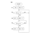
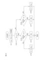
- FIG. 9 is a flowchart showing the steps of the weight setting process performed by the weight setting unit 52 in the driving assistance mode.
- the weight setting unit 52 sets the first weight W1 to 1 and the second weight W2 to 0 (step S1). As a result, the control mode of the electric motor 18 becomes the first control mode in which the electric motor 18 is driven and controlled only by the assist torque command value T asst .
- the automatic steering command value ⁇ AD,cmd is set by the host ECU 201 , and the automatic steering command value ⁇ AD,cmd , the mode signal S mode and the lateral deviation e L are provided to the motor control ECU 202 .
- the weight setting unit 52 determines whether the absolute value
- the predetermined value ⁇ is a value greater than 0, and is set to a value within the range of 0.2 m to 1.75 m, for example.
- step S2 If the absolute value
- step S2 when it is determined that the absolute value
- the time for gradually decreasing the first weight W1 from 1 to 0 may be, for example, about 0.1 seconds.
- the control mode of the electric motor 18 becomes a second control mode in which the electric motor 18 is drive-controlled by the integrated motor torque command value Tmint ,cmd .
- the electric motor 18 is controlled based on the sum of the assist torque command value W1 ⁇ T asst after multiplication by the first weight and the integrated motor torque command value w2 ⁇ T mint,cmd after multiplication by the second weight.
- the electric motor 18 is controlled based on the integrated angle command value ⁇ int,cmd , which is the sum of the manual steering command value ⁇ MD,cmd and the automatic steering command value ⁇ AD, cmd, so that the steering reaction force based on the virtual road load torque T rl used in the calculation of the manual steering command value ⁇ MD,cmd is reflected.
- the weight setting unit 52 determines whether or not the absolute value
- step S4 NO
- the weight setting unit 52 returns to step S4.
- step S4 when it is determined that the absolute value
- the time for gradually increasing the first weight W1 from 0 to 1 may be, for example, about 0.1 seconds.
- the control mode of the electric motor 18 becomes the first control mode. Note that while the first weight W1 is gradually increasing (while the second weight W2 is gradually decreasing), the electric motor 18 is controlled based on the sum of the assist torque command value W1 ⁇ T asst after multiplication by the first weight and the integrated motor torque command value w2 ⁇ T mint,cmd after multiplication by the second weight.
- the steering reaction force based on the virtual road load torque T rl used in the calculation of the manual steering command value ⁇ MD,cmd is not reflected.
- step S5 the weight setting unit 52 returns to step S2.
- the weight setting unit 52 sets the first weight W1 to 1 and the second weight W2 to 0. Therefore, in the normal mode, the electric motor 18 is controlled to be driven based only on the assist torque command value T asst .
- the road surface reaction force characteristic setting unit 43 sets a virtual load spring stiffness coefficient k and a virtual load viscous damping coefficient c used in the calculation of the manual steering command value ⁇ MD,cmd .
- the calculation of the manual steering command value ⁇ MD,cmd is performed by the manual steering command value generating unit 45 (see FIG. 2).
- a first virtual load spring stiffness coefficient kr( eL ) and a second virtual load spring stiffness coefficient kg are prepared as the virtual load spring stiffness coefficient k used in the driving assistance mode, while only one type of virtual load viscous damping coefficient c( eL ) is prepared as the virtual load viscous damping coefficient c used in the driving assistance mode.
- FIG. 10 is a graph showing an example of setting the first virtual load spring stiffness coefficient kr(e L ) and the second virtual load spring stiffness coefficient kg with respect to the lateral deviation e L .
- the first virtual load spring stiffness coefficient kr( eL ) is set to a constant value k1 when the absolute value
- k1 is a predetermined value greater than 0.
- the first virtual load spring stiffness coefficient kr( eL ) is set according to a characteristic that increases as the absolute value
- the first virtual load spring stiffness coefficient kr( eL ) changes linearly from k1 to k2, but it may change nonlinearly.
- the second virtual load spring stiffness coefficient kg is set to a constant value k3 regardless of the lateral deviation eL .
- k3 is set to a value larger than 0 and smaller than k1.
- the value of the first virtual load spring stiffness coefficient kr(e L ) with respect to the lateral deviation e L shown in Fig. 10 is stored in the memory as a first spring stiffness coefficient map. Also, the value k3 of the second virtual load spring stiffness coefficient kg shown in Fig. 10 is stored in the memory as the second virtual load spring stiffness coefficient kg.
- FIG. 11 is a graph showing an example of setting the virtual load viscous damping coefficient c(e L ) relative to the lateral deviation e L .
- the virtual load viscous damping coefficient c( eL ) is set to a constant value c1 when the absolute value
- c1 is a predetermined value greater than 0.
- the virtual load viscous damping coefficient c( eL ) is set from c1 to c2, which is greater than c1, in accordance with a characteristic that increases as the absolute value
- the virtual load viscous damping coefficient c( eL ) changes linearly from c1 to c2, but it may change nonlinearly.
- the values of the virtual load viscous damping coefficient c(e L ) with respect to the lateral deviation e L shown in FIG. 11 are stored in a memory as a viscous damping coefficient map.
- the road surface reaction force characteristic setting unit 43 sets the value of the virtual load viscous damping coefficient c based on a viscous damping coefficient map that stores the value of the virtual load viscous damping coefficient c( eL ) for the lateral deviation eL in Fig. 11 and the lateral deviation eL from the host ECU 201.
- the road surface reaction force characteristic setting unit 43 may set a predetermined virtual load viscous damping coefficient value (fixed value) that is set in advance as the virtual load viscous damping coefficient c.
- the road reaction force characteristic setting unit 43 executes a spring stiffness coefficient setting process to set the virtual load spring stiffness coefficient k.
- the spring stiffness coefficient setting process will be described later.
- the state in which the vehicle is moving toward the lane boundary (the driver is steering the vehicle so that it moves toward the lane boundary) is referred to as the "state in which the vehicle is heading toward the departure side.”
- the state in which the vehicle is moving toward the center of the lane (the state in which the vehicle is trying to return to the center of the lane) is referred to as the "state in which the vehicle is heading toward the departure avoidance side.”
- the road surface reaction force characteristic setting unit 43 determines that the vehicle is heading toward the departure avoidance side.
- the road surface reaction force characteristic setting unit 43 determines that the vehicle is heading toward the departure side.
- the reason for setting the predetermined threshold value ⁇ is to prevent frequent switching between a state in which the vehicle is heading toward the departure avoidance side and a state in which the vehicle is heading toward the departure side when the time differential value d ⁇ A /dt is within the range of the threshold value ⁇ .
- the reason why the road surface reaction force characteristic setting unit 43 determines that the vehicle is heading toward the departure side when the time differential value d ⁇ A /dt/dt is greater than - ⁇ and less than ⁇ is that when the vehicle reference position is located near the center of the lane, and the driver is holding the steering wheel in a neutral position and the vehicle is heading even slightly toward the lane boundary, the road surface reaction force characteristic setting unit 43 determines that the vehicle is heading toward the departure side.
- the road surface reaction force characteristic setting unit 43 may determine that the vehicle is moving toward the departure-avoidance side.
- 12A, 12B, and 12C are schematic diagrams showing examples of the angle deviation ⁇ A between the automatic steering command value ⁇ AD,cmd and the actual steering angle ⁇ when the vehicle reference position is to the right of the center of the lane.
- the steering angle of the large steering wheel 301 typically represents the actual steering angle ⁇
- the steering angle of the small steering wheel 302 typically represents the automatic steering command value ⁇ AD,cmd .
- 12A is a schematic diagram showing an example of the position of the vehicle 300 when the vehicle reference position is to the right of the lane center 313.
- Reference numeral 311 denotes the white line of the left lane boundary
- reference numeral 312 denotes the white line of the right lane boundary. In this case, the sign of the lateral deviation eL is negative.
- the actual steering angle ⁇ and the automatic steering command value ⁇ AD,cmd have this relationship, for example, when the driver turns the steering wheel in the left steering direction (positive direction), the angle deviation ⁇ A becomes large and the time differential value d ⁇ A /dt becomes positive.
- the actual steering angle ⁇ and the automatic steering command value ⁇ AD,cmd have this relationship, for example, when the driver turns the steering wheel in the left steering direction (positive direction), the angle deviation ⁇ A becomes large (approaching 0), and the time differential value d ⁇ A /dt becomes positive.
- the road surface reaction force characteristic setting unit 43 determines that the vehicle is heading toward the departure avoidance side.
- the road surface reaction force characteristic setting unit 43 determines that the vehicle is heading toward the departure side.
- the reason why the road surface reaction force characteristic setting section 43 determines that the vehicle is heading toward the departure side when the time differential value d ⁇ A /dt/dt is greater than ⁇ and less than ⁇ is as described above.
- the road surface reaction force characteristic setting unit 43 may determine that the vehicle is moving toward the departure-avoidance side.
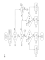
- FIG. 13 is a flowchart showing the steps of the spring stiffness coefficient setting process performed by the road surface reaction force characteristic setting unit 43 in the driving assistance mode.
- the spring stiffness coefficient setting process shown in FIG. 13 is started every time the driving assistance mode is started, and is repeatedly executed at a predetermined calculation cycle until the driving assistance mode is cancelled.
- the road surface reaction force characteristic setting unit 43 first obtains the lateral deviation eL and the automatic steering command value ⁇ AD ,cmd given by the host ECU 201, and the actual steering angle ⁇ calculated by the reduction ratio division unit 42 (step S11).
- the road surface reaction force characteristic setting unit 43 determines whether or not the lateral deviation eL is smaller than 0 (step S12). In other words, the road surface reaction force characteristic setting unit 43 determines whether or not the sign of the lateral deviation eL is negative.
- step S13 If the time differential value d ⁇ A /dt is equal to or larger than ⁇ (step S13: YES), the road surface reaction force characteristic setting unit 43 determines that the vehicle is moving toward the departure avoidance side, and sets the second virtual load spring stiffness coefficient kg as the virtual load spring stiffness coefficient k (step S14).Then, the processing for the current calculation cycle is terminated.
- step S13 If it is determined in step S13 that the time differential value d ⁇ A /dt is less than ⁇ (step S13: NO), the road surface reaction force characteristic setting unit 43 determines that the vehicle is heading toward the departure side and sets the first virtual load spring stiffness coefficient kr(e L ) as the virtual load spring stiffness coefficient k (step S15).
- the road surface reaction force characteristic setting unit 43 sets the value of the first virtual load spring stiffness coefficient kr( eL ) corresponding to the lateral deviation eL as the virtual load spring stiffness coefficient k, based on the first spring stiffness coefficient map in which the value of the first virtual load spring stiffness coefficient kr( eL ) for the lateral deviation eL in Fig. 10 is stored and the lateral deviation eL acquired in step S11. Then, the processing for the current calculation cycle is terminated.
- step S12 If it is determined in step S12 that the lateral deviation eL is equal to or greater than 0 (step S12: NO), the road surface reaction force characteristic setting unit 43 determines whether the time differential value d ⁇ A /dt is equal to or less than ⁇ (step S16).
- step S16 If the time differential value d ⁇ A /dt is equal to or smaller than ⁇ (step S16: YES), the road surface reaction force characteristic setting unit 43 determines that the vehicle is moving toward the departure avoidance side, and sets the second virtual load spring stiffness coefficient kg as the virtual load spring stiffness coefficient k (step S17).Then, the processing for the current calculation cycle ends.
- step S16 If it is determined in step S16 that the time differential value d ⁇ A /dt is greater than ⁇ (step S16: NO), the road surface reaction force characteristic setting unit 43 determines that the vehicle is heading toward the departure side, and sets the first virtual load spring stiffness coefficient kr(e L ) as the virtual load spring stiffness coefficient k (step S18), and ends the processing for the current calculation cycle.
- steps S14 and S17 if the first virtual load spring stiffness coefficient kr(e L ) was set as the virtual load spring stiffness coefficient k in the previous calculation cycle, it is preferable to gradually decrease the virtual load spring stiffness coefficient k from the previous value of the virtual load spring stiffness coefficient k to the value of the second virtual load spring stiffness coefficient kg.
- steps S15 and S18 if the second virtual load spring stiffness coefficient kg was set as the virtual load spring stiffness coefficient k in the previous calculation cycle, it is preferable to gradually increase the virtual load spring stiffness coefficient k from the previous value of the virtual load spring stiffness coefficient k to the value of the first virtual load spring stiffness coefficient kr(e L ).
- the first weight W1 is set to 1 and the second weight W2 is set to 0, so that the manual steering command value ⁇ MD,cmd is not reflected in the motor torque command value T m,cmd .
- the steering reaction force based on the manual steering command value ⁇ MD,cmd is not reflected.
- the road surface reaction force characteristic setting unit 43 is made to set the virtual load spring stiffness coefficient k and the virtual load viscous damping coefficient c.
- the road surface reaction force characteristic setting unit 43 sets the virtual load spring stiffness coefficient k to a preset value kM , and sets the virtual load viscous damping coefficient c to a preset value cM .
- kM may be set to k1 in Fig. 10, for example.
- cM may be set to c1 in Fig. 11, for example.
- the operation of the manual steering command value generating unit 45 may be stopped in normal mode.
- the road reaction force characteristic setting unit 43 does not need to set the virtual load spring stiffness coefficient k and the virtual load viscous damping coefficient c in normal mode.
- the first virtual load spring stiffness coefficient kr(e L ) is set as the virtual load spring stiffness coefficient k.
- the second virtual load spring stiffness coefficient kg is set as the virtual load spring stiffness coefficient k.
- a steering reaction force can be applied to the driver in a new way in the driving assistance mode.
- the steering reaction force increases as the distance from the center of the lane of the vehicle reference position increases, so the vehicle can effectively avoid departure from the lane.
- the steering reaction force is smaller than when the vehicle is heading toward the departure side, so vehicle behavior is stabilized and the sense of discomfort felt by the driver is reduced.
- the second virtual load spring stiffness coefficient kg is preferably smaller than the first virtual load spring stiffness coefficient kr(e L ).
- the first weight W1 is set to 1 and the second weight W2 is set to 0, so that the manual steering command value ⁇ MD,cmd is not reflected in the motor torque command value T m,cmd .
- the steering reaction force based on the manual steering command value ⁇ MD,cmd is not reflected. Even in this way, the vehicle does not deviate from the lane because the vehicle reference position is relatively close to the center of the lane.
- the control gain is changed based on the yaw angle of the vehicle relative to the driving lane. Since there is a delay in detecting the yaw angle relative to the driver's operation, there is a problem in that the timing for changing the control gain in response to the driver's operation is delayed.
- a determination is made as to whether the vehicle is heading toward the departure side or toward the departure avoidance side based on a time differential value d ⁇ A /dt of the angle deviation ⁇ A ( ⁇ - ⁇ AD,cmd ) between the actual steering angle ⁇ and the automatic steering command value ⁇ AD,cmd, and the virtual load spring stiffness coefficient k is switched based on the determination result. Since this time differential value d ⁇ A /dt is unlikely to cause a delay in response to the driver's operation, the virtual load spring stiffness coefficient k can be switched quickly in response to a switch in the steering direction by the driver. This allows the driver to obtain an intuitive steering feel.
- both the virtual load spring stiffness coefficient k and the virtual load viscous damping coefficient c are switched depending on whether it is determined that the vehicle is heading toward the departure side or the departure avoidance side.
- a first virtual load spring stiffness coefficient kr( eL ) and a second virtual load spring stiffness coefficient kg are prepared as the virtual load spring stiffness coefficient k
- FIG. 14 is a graph showing an example of setting the first virtual load viscous damping coefficient cr(e L ) and the second virtual load viscous damping coefficient cg with respect to the lateral deviation e L .
- the first virtual load viscous damping coefficient cr( eL ) is set to a constant value c1 when the absolute value
- c1 is a predetermined value greater than 0.
- the first virtual load viscous damping coefficient cr( eL ) is set according to a characteristic that increases as the absolute value
- the first virtual load viscous damping coefficient cr( eL ) changes linearly from c1 to c2, but it may change nonlinearly.
- the second virtual load viscous damping coefficient cg is set to a constant value c3 regardless of the lateral deviation eL .
- c3 is set to a value greater than 0 and less than c1.
- the second virtual load viscous damping coefficient cg is smaller than the first virtual load viscous damping coefficient cr( eL ).
- the second virtual load viscous damping coefficient cg may be set to a value (c4) greater than c1 in order to make the return of the steering reaction force gentler.
- the value of the first virtual load viscous damping coefficient cr( eL ) with respect to the lateral deviation eL shown in Fig. 14 is stored in the memory as a first viscous damping coefficient map. Also, the value c3 or c4 of the second virtual load viscous damping coefficient cg shown in Fig. 14 is stored in the memory.
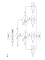
- FIG. 15 is a flowchart showing the procedure for the road surface reaction force characteristic setting process performed by the road surface reaction force characteristic setting unit 43 according to the first modified example when in driving assistance mode.
- the road surface reaction force characteristic setting process shown in FIG. 15 is started each time the driving assistance mode is started, and is repeatedly executed at a predetermined calculation cycle until the driving assistance mode is cancelled.
- steps S14A, S15A, S17A, and S18A are different from the processes of steps S14, S15, S17, and S18 in FIG. 13, respectively.
- the processes of the other steps S11, S12, S13, and S16 are the same as the processes of steps S11, S12, S13, and S16 in FIG. 13, respectively.
- the road reaction force characteristic setting unit 43 sets the second virtual load spring stiffness coefficient kg as the virtual load spring stiffness coefficient k, and sets the second virtual load viscous damping coefficient cg as the virtual load viscous damping coefficient c. Then, the processing for this calculation cycle ends.
- the road surface reaction force characteristic setting unit 43 sets the first virtual load spring stiffness coefficient kr(e L ) as the virtual load spring stiffness coefficient k, and sets the first virtual load viscous damping coefficient cr(e L ) as the virtual load viscous damping coefficient c.
- the road surface reaction force characteristic setting unit 43 sets the value of the first virtual load spring stiffness coefficient kr corresponding to the lateral deviation eL as the virtual load spring stiffness coefficient k , based on a first spring stiffness coefficient map in which values of the first virtual load spring stiffness coefficient kr for the lateral deviation eL in FIG. 10 are stored and on the basis of the lateral deviation eL acquired in step S11.
- the road surface reaction force characteristic setting unit 43 sets the value of the first virtual load viscous damping coefficient cr( eL ) corresponding to the lateral deviation eL in Figure 14 as the virtual load viscous damping coefficient c based on the lateral deviation eL acquired in step S11 and the first viscous damping coefficient map that stores the value of the first virtual load viscous damping coefficient cr( eL ) for the lateral deviation eL in Figure 14.
- the operation of the road reaction force characteristic setting unit 43 in normal mode is the same as in the first embodiment described above.
- the road surface reaction force characteristic setting unit 43 sets the value of the virtual load spring stiffness coefficient k based on, for example, a viscous damping coefficient map in which the value of the first virtual load spring stiffness coefficient kr( eL ) with respect to the lateral deviation eL in Fig. 10 is stored and the lateral deviation eL from the host ECU 201.
- the road surface reaction force characteristic setting unit 43 may set a predetermined virtual load spring stiffness coefficient value (fixed value) that is set in advance as the virtual load spring stiffness coefficient k.
- the virtual load viscous damping coefficient c for example, two types of damping coefficients are prepared: a first virtual load viscous damping coefficient cr( eL ) and a second virtual load viscous damping coefficient cg shown in Fig. 14.
- the value of the first virtual load viscous damping coefficient cr( eL ) for the lateral deviation eL shown in Fig. 14 is stored in memory as a first viscous damping coefficient map.
- the value c3 of the second virtual load viscous damping coefficient cg shown in Fig. 14 is stored in memory.
- the road reaction force characteristic setting unit 43 executes a viscous damping coefficient setting process to set the virtual load viscous damping coefficient c.
- FIG. 16 is a flowchart showing the steps of the viscous damping coefficient setting process performed by the road surface reaction force characteristic setting unit 43 in the driving assistance mode.
- the viscous damping coefficient setting process shown in FIG. 16 is started each time the driving assistance mode is started, and is repeatedly executed at a predetermined calculation cycle until the driving assistance mode is cancelled.
- steps S14B, S15B, S17B, and S18B differ from those of steps S14, S15, S17, and S18 in FIG. 13, respectively.
- the processes of the other steps S11, S12, S13, and S16 are the same as those of steps S11, S12, S13, and S16 in FIG. 13, respectively.
- the road reaction force characteristic setting unit 43 sets the second virtual load viscous damping coefficient cg as the virtual load viscous damping coefficient c. Then, the processing for this calculation cycle ends.
- the road surface reaction force characteristic setting unit 43 sets the first virtual load viscous damping coefficient cr(e L ) as the virtual load viscous damping coefficient c.
- the road surface reaction force characteristic setting unit 43 sets the value of the first virtual load viscous damping coefficient cr( eL ) corresponding to the lateral deviation eL in Figure 14 as the first virtual load viscous damping coefficient c based on the spring stiffness coefficient map that stores the value of the first virtual load viscous damping coefficient cr( eL ) for the lateral deviation eL in Figure 14 and the lateral deviation eL acquired in step S11.
- the operation of the road reaction force characteristic setting unit 43 in normal mode is the same as in the first embodiment described above.
- the weight setting unit 52 sets the first weight W1 and the second weight W2 based on the mode signal S mode and the lateral deviation e L.
- the weight setting unit 52 according to the modified example sets the first weight W1 and the second weight W2 based only on the mode signal S mode .
- the weight setting unit 52 sets the first weight W1 to 1 and the second weight W2 to 0.
- the weight setting unit 52 sets the first weight W1 to 0 and the second weight W2 to 1.
- the rest is the same as in the first embodiment described above.
- the operation of the road surface reaction force characteristic setting unit 43 is the same as the operation shown in FIG. 13 of the first embodiment described above.
- the first virtual load spring stiffness coefficient kr(e L ) is set as the virtual load spring stiffness coefficient k.
- the second virtual load spring stiffness coefficient kg is set as the virtual load spring stiffness coefficient k.
- the first weight W1 is set to 0 and the second weight W2 is set to 1. Therefore, even when the vehicle reference position is within ⁇ from the center of the lane in the driving assistance mode, the steering reaction force based on the manual steering command value ⁇ MD,cmd is reflected.
- the weight setting unit 52 according to the modified example can be used as the weight setting unit 52.
- the weight setting unit 52 sets the first weight W1 to 1 and the second weight W2 to 0.
- the weight setting unit 52 sets the first weight W1 to 0 and the second weight W2 to 1.
- the road surface reaction force characteristic setting unit 43 acquires the lateral deviation eL and the automatic steering command value ⁇ AD, cmd given by the host ECU 201 and the actual steering angle ⁇ calculated by the reduction ratio division unit 42 at each predetermined calculation cycle during the driving assistance mode. Next, the road surface reaction force characteristic setting unit 43 determines whether the lateral deviation eL is within the range of - ⁇ to + ⁇ . Then, the road surface reaction force characteristic setting unit 43 performs processing according to the determination result. In other words, in the second embodiment, different operations are performed when the lateral deviation eL is within the range of - ⁇ to + ⁇ and when the lateral deviation eL is outside the range of - ⁇ to + ⁇ .
- the road surface reaction force characteristic setting unit 43 performs the process of step S12 and subsequent steps in the first embodiment shown in Fig. 13.
- the virtual load viscous damping coefficient c used at this time the virtual load viscous damping coefficient c(eL) shown in Fig. 11 may be used, or a predetermined value (fixed value) may be used.
- the road surface reaction force characteristic setting unit 43 sets the virtual load spring stiffness coefficient k to a predetermined value (e.g., k1 in FIG. 10) and sets the virtual load viscous damping coefficient c to a predetermined value (e.g., c1 in FIG. 11) without determining whether the vehicle is in a state heading toward the departure avoidance side or the departure side.
- the road surface reaction force characteristic setting unit 43 may perform the following operation depending on the determination result of whether the lateral deviation eL is within the range of - ⁇ to + ⁇ during the driving assistance mode. That is, when it is determined that the lateral deviation eL is outside the range of - ⁇ to + ⁇ , the road surface reaction force characteristic setting unit 43 performs the process from step S12 in Fig. 15 described above. On the other hand, when it is determined that the lateral deviation eL is within the range of - ⁇ to + ⁇ , the road surface reaction force characteristic setting unit 43 sets the virtual load spring stiffness coefficient k and the virtual load viscous damping coefficient c to predetermined values that have been set in advance.
- the road surface reaction force characteristic setting unit 43 may perform the following operation depending on the determination result of whether or not the lateral deviation eL is within the range of - ⁇ to + ⁇ . That is, when it is determined that the lateral deviation eL is outside the range of - ⁇ to + ⁇ , the road surface reaction force characteristic setting unit 43 performs the process from step S12 in Fig. 16 described above. On the other hand, when it is determined that the lateral deviation eL is within the range of - ⁇ to + ⁇ , the road surface reaction force characteristic setting unit 43 sets the virtual load spring stiffness coefficient k and the virtual load viscous damping coefficient c to predetermined values that have been set in advance.
- the weight setting unit 52 sets the first weight W1 to 1 and the second weight W2 to 0.
- the weight setting unit 52 sets the first weight W1 to 0 and the second weight W2 to 1.
- the road surface reaction force characteristic setting unit 43 performs different operations depending on whether the lateral deviation eL is within the range of - ⁇ to + ⁇ or outside the range of - ⁇ to + ⁇ .
- the road reaction force characteristic setting unit 43 performs the road reaction force characteristic setting process shown in FIG. 17 during the driving assistance mode.
- FIG. 17 the same steps as in FIG. 13 are indicated with the same step numbers as in FIG. 13.
- the road reaction force characteristic setting process shown in FIG. 17 is started every time the driving assistance mode is started, and is repeatedly executed at a predetermined calculation cycle until the driving assistance mode is cancelled.
- the road surface reaction force characteristic setting unit 43 first obtains the lateral deviation eL and the automatic steering command value ⁇ AD ,cmd given by the host ECU 201, and the actual steering angle ⁇ calculated by the reduction ratio division unit 42 (step S11).
- the road surface reaction force characteristic setting unit 43 determines whether the lateral deviation eL is within the range of - ⁇ eL ⁇ + ⁇ (step S21). In other words, the road surface reaction force characteristic setting unit 43 determines whether the lateral deviation eL is within the range of - ⁇ to + ⁇ .
- step S21 NO
- the road surface reaction force characteristic setting unit 43 proceeds to step S12. Specifically, the road surface reaction force characteristic setting unit 43 determines whether the lateral deviation eL is smaller than 0.
- steps S12 to S18 are the same as those in steps S12 to S18 in FIG. 13, and therefore detailed description thereof will be omitted.
- step S22 YES
- the road surface reaction force characteristic setting unit 43 proceeds to step S13.
- step S22 NO
- the road surface reaction force characteristic setting unit 43 proceeds to step S16.
- the state where the actual steering angle ⁇ and the automatic steering command value ⁇ AD,cmd are in the relationship shown in FIG. 12C (the vehicle is on the right side of the lane center, and ⁇ - ⁇ AD,cmd ⁇ 0) and the lateral deviation e L is in the range of - ⁇ e L ⁇ + ⁇ is defined as the first state.
- the first state for example, when the driver turns the steering wheel in the left steering direction (positive direction), the angle deviation ⁇ A becomes large and the time differential value d ⁇ A /dt becomes positive. In this case, the answer is YES in step S21 of FIG.
- step S22 the answer is YES in step S22, and when the time differential value d ⁇ A /dt exceeds the threshold value ⁇ , the answer is YES in step S13.
- the second virtual load spring stiffness coefficient kg is set as the virtual load spring stiffness coefficient k. That is, the result is the same as the process (process of FIG. 13) when it is determined that the lateral deviation eL is outside the range of - ⁇ eL ⁇ + ⁇ .
- the angle deviation ⁇ A becomes smaller and the time differential value d ⁇ A /dt becomes negative.
- the answer is YES in step S21 of Fig. 17, the answer is YES in step S22, and the answer is NO in step S13.
- the first virtual load spring stiffness coefficient kr( eL ) is set as the virtual load spring stiffness coefficient k.
- the result is the same as the process (process of Fig. 13) when it is determined that the lateral deviation eL is outside the range of - ⁇ eL ⁇ + ⁇ .
- the second state refers to a state in which the actual steering angle ⁇ and the automatic steering command value ⁇ AD,cmd are in the relationship shown in FIG. 12B (the vehicle is on the right side of the lane center, and ⁇ - ⁇ AD,cmd ⁇ 0) and the lateral deviation e L is in the range of - ⁇ e L ⁇ + ⁇ .
- the second state for example, when the driver turns the steering wheel in the left steering direction (positive direction), the angle deviation ⁇ A becomes large and the time differential value d ⁇ A /dt becomes positive.
- the answer is YES in step S21 of FIG. 17, the answer is NO in step S22, and the answer is NO in step S16.
- the first virtual load spring stiffness coefficient kr(e L ) is set as the virtual load spring stiffness coefficient k.
- the result is different from the process (process of FIG. 13) when it is determined that the lateral deviation e L is outside the range of - ⁇ e L ⁇ + ⁇ .
- the lateral deviation e L is within the range of - ⁇ to + ⁇
- ⁇ AD,cmd it is determined that the vehicle is heading toward the departure side.
- the driver turns the wheel back too much and there is a high possibility that the vehicle will go beyond the center of the lane, it is determined that the vehicle is heading toward the departure side.
- the result is YES in step S21 of FIG. 17 and NO in step S22, and if the time differential value d ⁇ A /dt falls below the threshold value - ⁇ , the result is YES in step S16.
- the second virtual load spring stiffness coefficient kg is set as the virtual load spring stiffness coefficient k.
- the result is different from the process (process of FIG. 13) when it is determined that the lateral deviation eL is outside the range of - ⁇ eL ⁇ + ⁇ .
- the road reaction force characteristic setting unit 43 may perform the processes of steps S14A, S15A, S17A, and S18A in FIG. 15 instead of the processes of steps S14, S15, S17, and S18 in FIG. 17.
- the road reaction force characteristic setting unit 43 may perform the processes of steps S14B, S15B, S17B, and S18B in FIG. 16 instead of the processes of steps S14, S15, S17, and S18 in FIG. 17, respectively.
- the weight setting unit 52 sets the first weight W1 to 1 and the second weight W2 to 0.
- the weight setting unit 52 sets the first weight W1 to 0 and the second weight W2 to 1.
- the road reaction force characteristic setting unit 43 performs the road reaction force characteristic setting process shown in FIG. 18 during the driving assistance mode.
- FIG. 18 the same steps as in FIG. 13 are indicated with the same step numbers as in FIG. 13.
- the road reaction force characteristic setting process shown in FIG. 18 is started every time the driving assistance mode is started, and is repeatedly executed at a predetermined calculation cycle until the driving assistance mode is cancelled.
- the process other than step S12 in Fig. 13 is the same as the process described in the first embodiment.
- the virtual load viscous damping coefficient c used in the driving assistance mode may be used, or a predetermined value (fixed value) that is set in advance may be used.
- the road reaction force characteristic setting unit 43 may perform the processes of steps S14A, S15A, S17A, and S18A in FIG. 15 instead of the processes of steps S14, S15, S17, and S18 in FIG. 18, respectively.
- the road reaction force characteristic setting unit 43 may perform the processes of steps S14B, S15B, S17B, and S18B in FIG. 16 instead of the processes of steps S14, S15, S17, and S18 in FIG. 18, respectively.
- Fig. 19 is a block diagram showing a first modified example of the motor control ECU, in which parts corresponding to those in Fig. 2 are denoted by the same reference numerals as in Fig. 2.
- a motor control ECU 202A in FIG. 19 differs from the motor control ECU 202 in FIG. 2 in the following (1) and (2).
- a motion equation setting unit 43A is provided in place of the road reaction force characteristic setting unit 43 in FIG. (2)
- the configuration of the manual steering command value generating unit 45A is different from the configuration of the manual steering command value generating unit 45 in FIG.
- the equation of motion setting unit 43A sets a target virtual spring reaction force T tb,d (e L ) based on the lateral deviation e L provided by the host ECU 201.
- the equation of motion setting unit 43A also sets a virtual load spring stiffness coefficient kmd and a virtual load viscous damping coefficient cmd used by the manual steering command value generating unit 45A.
- the equation of motion setting unit 43A also sets third to sixth weights W3 to W6 used by the manual steering command value generating unit 45A. In the driving assistance mode, the equation of motion setting unit 43A performs a coefficient/weight setting process, which will be described later.
- the weight setting unit 52 sets the first weight W1 to 1 and the second weight W2 to 0.
- the weight setting unit 52 sets the first weight W1 to 0 and the second weight W2 to 1.
- the assist torque T asst set by the assist torque command value setting unit 44 is provided as the motor torque command value T m,cmd to the torque control unit 51.
- the driving mode is the driving assistance mode
- the integrated motor torque command value T mint,cmd calculated by the angle control unit 47 is provided as the motor torque command value T m,cmd to the torque control unit 51.
- FIG. 20 is a graph showing an example of setting the target virtual spring reaction force T tb,d (e L ) relative to the lateral deviation e L .
- the target virtual spring reaction force Ttb,d ( eL ) is set to increase as the lateral deviation eL increases from -Ttb ,d,s (where Ttb ,d,s >0) to Ttb ,d, s.
- the target virtual spring reaction force Ttb,d ( eL ) changes linearly, but may change nonlinearly.
- eL,s is set to a predetermined value that is greater than zero and less than 1/2 the width of the travel lane.
- the target virtual spring reaction force Ttb ,d ( eL ) is set to increase as the lateral deviation eL increases from Ttb,d,s to Ttb ,d,m (where Ttb ,d,m > Ttb,d,s ).
- the slope of the straight line representing the target virtual spring reaction force Ttb,d ( eL ) is set to be larger compared to the range of the lateral deviation eL from -eL, s to eL,s .
- the target virtual spring reaction force Ttb,d ( eL ) changes linearly, but it may change nonlinearly.
- the target virtual spring reaction force T tb,d (e L ) is set to T tb,d,m .
- the target virtual spring reaction force Ttb,d ( eL ) is set to be smaller as the lateral deviation eL becomes smaller from -Ttb ,d,s to -Ttb ,d,m (where -Ttb,d,m ⁇ -Ttb ,d,s ).
- the slope of the straight line representing the target virtual spring reaction force Ttb,d ( eL ) is set to be larger compared to the range of the lateral deviation eL from -eL, s to eL,s .
- the target virtual spring reaction force Ttb,d ( eL ) changes linearly, but may change nonlinearly.
- the target virtual spring reaction force T tb,d (e L ) is set to ⁇ T tb,d,m .
- the target virtual spring reaction force T tb,d (e L ) set by the motion equation setting unit 43A is provided to the manual steering command value generating unit 45A.
- a first virtual load spring stiffness coefficient kr and a second virtual load spring stiffness coefficient kg are prepared as the virtual load spring stiffness coefficient kmd used in the driving assistance mode.
- FIG. 21 is a graph showing an example of setting the first virtual load spring stiffness coefficient kr and the second virtual load spring stiffness coefficient kg with respect to the lateral deviation eL .
- the first virtual load spring stiffness coefficient kr is set only when the absolute value
- the first virtual load spring stiffness coefficient kr is set to a constant value k1 regardless of the lateral deviation eL .
- k1 is a predetermined value greater than 0.
- the second virtual load spring stiffness coefficient kg is set to a constant value k3 regardless of the lateral deviation eL . k3 is set to a value greater than 0 and less than k1.
- the value k1 of the first virtual load spring stiffness coefficient kr and the value k3 of the second virtual load spring stiffness coefficient kg shown in FIG. 21 are stored in memory.
- a first virtual load viscous damping coefficient cr(e L ) and a second virtual load viscous damping coefficient cg are prepared as the virtual load viscous damping coefficient cmd used in the driving assistance mode.
- FIG. 22 is a graph showing an example of setting the first virtual load viscous damping coefficient cr(e L ) and the second virtual load viscous damping coefficient cg with respect to the lateral deviation e L .
- the first virtual load viscous damping coefficient c( eL ) is set to a constant value c1 when the absolute value
- c1 is a predetermined value greater than 0.
- the first virtual load viscous damping coefficient c( eL ) is set according to a characteristic that increases as the absolute value
- the first virtual load viscous damping coefficient c( eL ) changes linearly from c1 to c2, but it may change nonlinearly.
- the second virtual load viscous damping coefficient cg is set to a constant value c3 regardless of the lateral deviation eL .
- c3 is set to a value larger than 0 and smaller than c1.
- the value of the first virtual load viscous damping coefficient c(e L ) with respect to the lateral deviation e L shown in Fig. 22 is stored in a memory as a viscous damping coefficient map. Also, the value c3 of the second virtual load viscous damping coefficient cg shown in Fig. 22 is stored in a memory.
- the manual steering command value generating unit 45A will now be described.
- the manual steering command value generating unit of the comparative example generates the manual steering command value ⁇ MD,cmd by using the reference EPS model of Fig. 23.
- the reference EPS model of Fig. 23 is an example of the "reference model for the steering device" of the present disclosure.
- This reference EPS model is a single inertia model including a lower column.
- the lower column corresponds to the output shaft 9 and the worm wheel 21.
- this model is only an example, and an inertia model including a configuration other than the above (for example, a rack bar, etc.) may be used.
- Jmd is the inertia of the lower column (hereinafter referred to as "column inertia")
- ⁇ col is the rotation angle of the lower column
- Ttb is the torsion bar torque.
- the lower column is supplied with the torsion bar torque Ttb , the torque N ⁇ Tm acting on the output shaft 9 from the electric motor 18, and the road reaction torque (virtual reaction force) Trl .
- the road surface reaction torque T rl is expressed by the following equation (10) using a virtual load spring stiffness coefficient kmd , which is the stiffness coefficient of the virtual spring, and a virtual load viscous damping coefficient cmd , which is the viscous damping coefficient of the virtual damper.
- the virtual load spring stiffness coefficient k md and the virtual load viscous damping coefficient c md are obtained in advance by experiment, analysis, etc.
- k md ⁇ col may be referred to as a virtual spring reaction force
- c md (d ⁇ col /dt) may be referred to as a virtual damper reaction force.
- J md ⁇ d 2 ⁇ col /dt 2 is the moment of inertia acting on the lower column.
- the manual steering command value generating unit of the comparative example substitutes the torsion bar torque Ttb detected by the torque sensor 12 for Ttb , substitutes the assist torque command value T asst set by the assist torque command value setting unit 44 for Tm , and calculates the rotation angle ⁇ col of the lower column by solving the differential equation of equation (11). Then, the manual steering command value generating unit of the comparative example generates the obtained rotation angle ⁇ col of the lower column as the manual steering command value ⁇ MD,cmd .
- the method of setting the manual steering command value ⁇ MD,cmd in this manner is referred to as a comparative method.
- Equation (11) is equivalent to an equation of motion in which T m is replaced by T asst and ⁇ col is replaced by ⁇ MD,cmd .
- the manual steering command value generating unit 45A calculates the manual steering command value ⁇ MD,cmd by utilizing the equation of motion (equation (11)) of the reference EPS model described above. Specifically, in this modification, the manual steering command value generating unit 45A calculates the manual steering command value ⁇ MD,cmd by utilizing an equation of motion obtained by modifying the equation of motion (equation (11)) of the reference EPS model described above.
- FIG. 24 is a block diagram showing the configuration of the manual steering command value generating unit 45A.
- Jmd is the column inertia.
- s is a differential operator.
- ⁇ MD,cmd is a manual steering command value, which corresponds to the rotation angle ⁇ col of the lower column in the comparison method.
- kmd is a virtual load spring stiffness coefficient, which is set by the motion equation setting unit 43A.
- cmd is a virtual load viscous damping coefficient, which is set by the motion equation setting unit 43A.
- Tasst is an assist torque command value set by the assist torque command value setting unit 44.
- the manual steering command value generating unit 45A includes a reduction ratio multiplication unit 431, an addition/subtraction unit 401, an inertia division unit 402, a first integration unit 403, a second integration unit 404, a virtual damper reaction force calculation unit 405, a first virtual spring reaction force calculation unit 406, a third weight multiplication unit 407, a second virtual spring reaction force calculation unit 408, a fifth weight multiplication unit 409, a first addition unit 410, a sixth weight multiplication unit 411, a second addition unit 412, a fourth weight multiplication unit 413, and a third addition unit 414.
- the reduction ratio multiplication unit 431 multiplies the assist torque command value T asst by the reduction ratio N of the reducer 19 to convert the assist torque command value T asst for the rotating shaft of the electric motor 18 into an assist torque command value N ⁇ T asst for the output shaft 9.
- the assist torque command value N ⁇ T asst for the output shaft 9 calculated by the reduction ratio multiplication unit 431 is provided to the addition and subtraction unit 401 and also to the first addition unit 410.
- the addition/subtraction unit 401 is supplied with the torsion bar torque Ttb , the assist torque command value N ⁇ T asst for the output shaft 9 calculated by the reduction ratio multiplication unit 431, the virtual damper reaction force cmd ⁇ d ⁇ MD,cmd /dt provided by the virtual damper reaction force calculation unit 405, and the addition result X of the third addition unit 414.
- the inertia division unit 402 calculates the second-order differential value d 2 ⁇ MD,cmd /dt 2 of the manual steering command value ⁇ MD,cmd by dividing the moment of inertia J md ⁇ d 2 ⁇ MD,cmd /dt 2 calculated by the addition and subtraction unit 401 by the column inertia J md .
- the first integration unit 403 calculates a first-order differential value d ⁇ MD,cmd /dt of the manual steering command value ⁇ MD,cmd by integrating a second-order differential value d 2 ⁇ MD, cmd /dt 2 of the manual steering command value ⁇ MD ,cmd .
- the second integral unit 404 calculates the manual steering command value ⁇ MD,cmd by integrating the first-order differential value d ⁇ MD,cmd /dt of the manual steering command value ⁇ MD,cmd .
- This manual steering command value ⁇ MD,cmd is output from the manual steering command value generating unit 45A.
- the virtual damper reaction force calculation unit 405 calculates a virtual damper reaction force c md ⁇ d ⁇ MD,cmd /dt by multiplying the first-order differential value d ⁇ MD,cmd /dt of the manual steering command value ⁇ MD,cmd calculated by the first integration unit 403 by a virtual load viscous damping coefficient c md .
- This virtual damper reaction force c md ⁇ d ⁇ MD ,cmd /dt is fed back to the addition and subtraction unit 401.
- the first virtual spring reaction force calculation section 406 multiplies the manual steering command value ⁇ MD,cmd calculated by the second integration section 404 by the virtual load spring stiffness coefficient kmd to calculate a first virtual spring reaction force kmd ⁇ MD,cmd .
- the third weight multiplier 407 multiplies the first virtual spring reaction force kmd ⁇ MD ,cmd by a third weight W3.
- a second virtual spring reaction force calculation section 408 multiplies the manual steering command value ⁇ MD,cmd calculated by the second integration section 404 by the virtual load spring stiffness coefficient kmd to calculate a second virtual spring reaction force kmd ⁇ MD,cmd .
- a fifth weight multiplier 409 multiplies the second virtual spring reaction force kmd ⁇ MD ,cmd by a fifth weight W5.
- the first adder 410 adds the target virtual spring reaction force T tb,d (e L ) to the assist torque command value N ⁇ T asst for the output shaft 9 calculated by the reduction ratio multiplier 431.
- the sixth weight multiplier 411 multiplies the calculation result (T tb,d (e L ) + N ⁇ T asst ) of the first adder 410 by a sixth weight W6.
- the second adder 412 adds the calculation result W5 ⁇ k md ⁇ MD,cmd of the fifth weight multiplier 409 and the calculation result W6 ⁇ (T tb,d (e L )+N ⁇ T asst ) of the sixth weight multiplier 411 .
- the fourth weight multiplication unit 413 multiplies the calculation result of the second adder 412 ⁇ W5 ⁇ k md ⁇ MD,cmd + W6 ⁇ (T tb,d (e L )+N ⁇ T asst ) ⁇ by a fourth weight W4.
- the third adder 414 adds the calculation result W3 ⁇ k md ⁇ MD,cmd of the third weight multiplier 407 and the calculation result W4 ⁇ W5 ⁇ k md ⁇ MD,cmd + W6 ⁇ (T tb,d (e L ) + N ⁇ T asst ) ⁇ of the fourth weight multiplier 413.
- the addition result [ ⁇ W3 ⁇ k md ⁇ MD,cmd ⁇ + W4 ⁇ W5 ⁇ k md ⁇ MD,cmd + W6 ⁇ (T tb,d (e L ) + N ⁇ T asst ) ⁇ ] of the third adder 414 is fed back to the addition and subtraction unit 401 as X.
- the third weight W3 is set to 1 and the fourth weight W4 is set to zero.
- the third weight W3 is set to zero and the fourth weight W4 is set to 1.
- the driving assistance mode becomes the lane centering assist mode (LCA mode)
- the fifth weight W5 is set to 1
- the sixth weight W6 is set to zero.
- the driving assistance mode becomes the lane keeping assist mode (LKA mode)
- the fifth weight W5 is set to zero
- the sixth weight W6 is set to one.
- the manual steering command value generating unit 45A calculates the manual steering command value ⁇ MD,cmd based on the equation of motion of the following equation (12).
- J md ⁇ d 2 ⁇ MD,cmd /dt 2 is the moment of inertia
- cg ⁇ d ⁇ MD,cmd /dt is the virtual damper reaction force
- kg ⁇ MD,cmd is the virtual spring reaction force
- the manual steering command value generating unit 45A calculates the manual steering command value ⁇ MD ,cmd by using cg ⁇ d ⁇ MD,cmd /dt as the virtual damper reaction force cmd ⁇ d ⁇ col /dt in the equation of motion of the above equation (11), and by using kg ⁇ MD,cmd as the virtual spring reaction force kmd ⁇ col in the equation of motion of the above equation (11) .
- the manual steering command value generating unit 45A calculates the manual steering command value ⁇ MD,cmd based on the equation of motion of the following equation (13).
- J md ⁇ d 2 ⁇ MD,cmd /dt 2 is the moment of inertia
- cr(e L ) ⁇ d ⁇ MD,cmd is the virtual damper reaction force
- kr ⁇ MD,cmd is the virtual spring reaction force
- the manual steering command value generating unit 45A calculates the manual steering command value ⁇ MD , cmd by using cr(e L ) ⁇ d ⁇ MD,cmd /dt corresponding to the lateral deviation e L as the virtual damper reaction force cmd ⁇ d ⁇ col /dt in the equation of motion of the above equation (11) and by using kr ⁇ MD,cmd as the virtual spring reaction force kmd ⁇ col in the equation of motion of the above equation (11). Therefore, in the LCA mode, the virtual damper reaction force and the virtual spring reaction force can be made larger than when the vehicle is in a state heading toward the departure avoidance side.
- the addition result X of the third adder 414 becomes Ttb,d ( eL )+N ⁇ Tasst ). Therefore, the calculation result of the addition and subtraction unit 401 becomes ( Ttb - cmd ⁇ d ⁇ MD ,cmd /dt- Ttb,d ( eL )). As will be described later, in this case, cmd is set to cr( eL ) (see FIG. 22), so the calculation result of the addition and subtraction unit 401 becomes ( Ttb -cr( eL ) ⁇ d ⁇ MD,cmd /dt- Ttb,d ( eL )).
- the manual steering command value generating unit 45A calculates the manual steering command value ⁇ MD,cmd based on the equation of motion of the following equation (14).
- J md ⁇ d 2 ⁇ MD,cmd /dt 2 is the moment of inertia
- cr(e L ) ⁇ d ⁇ MD,cmd is the virtual damper reaction force
- T tb,d (e L ) is the target virtual spring reaction force.
- the virtual damper reaction force can be made larger than when the vehicle is moving toward the departure avoidance side. Also, in the LKA mode, a steering reaction force corresponding to the lateral deviation eL can be applied to the driver compared to the LCA mode. This makes it easier for the driver to recognize the distance from the center of the traveling lane or the distance to the lane.
- the calculation result N ⁇ T asst of the reduction ratio multiplication unit 431 is provided to the first adder 410, but the calculation result N ⁇ T asst of the reduction ratio multiplication unit 431 does not have to be provided to the first adder 410.
- the manual steering command value generating unit 45A calculates the manual steering command value MD, cmd based on the equation of motion in which N ⁇ T asst is added to the right side of the above equation (14).
- 25A and 25B are flowcharts showing the steps of the coefficient/weight setting process performed by the equation of motion setting unit 43A in the driving assistance mode.
- the coefficient/weight setting process shown in FIG. 25A and FIG. 25B is started each time the driving assistance mode is started, and is repeatedly executed at a predetermined calculation cycle until the driving assistance mode is cancelled.
- the equation of motion setting unit 43A first obtains the lateral deviation eL and the automatic steering command value ⁇ AD ,cmd given by the host ECU 201, and the actual steering angle ⁇ calculated by the reduction ratio division unit 42 (step S31).
- the equation of motion setting unit 43A determines whether or not the lateral deviation eL is smaller than 0 (step S32). In other words, the equation of motion setting unit 43A determines whether or not the sign of the lateral deviation eL is negative.
- step S33 YES
- the equation of motion setting unit 43A determines that the vehicle is moving toward the departure avoidance side (non-departure side), and proceeds to step S34.
- step S34 the equation of motion setting unit 43A sets the third weight W3 to 1, the fourth weight W4 to 0, sets the second virtual load spring stiffness coefficient kg as the virtual load spring stiffness coefficient kmd , and sets the second virtual load viscous damping coefficient cg as the virtual load viscous damping coefficient cmd .
- the manual steering command value generating unit 45A calculates the manual steering command value ⁇ MD ,cmd based on the above equation (12).
- the equation of motion setting unit 43A ends the process for the current calculation cycle.
- step S33 If it is determined in step S33 that the time differential value d ⁇ A /dt is less than ⁇ (step S33: NO), the equation of motion setting unit 43A determines that the vehicle is heading toward the departure side, and proceeds to step S35.
- step S35 the equation of motion setting unit 43A sets the third weight W3 to 0 and the fourth weight W4 to 1. Furthermore, the equation of motion setting unit 43A sets the first virtual load viscous damping coefficient cr( eL ) as the virtual load viscous damping coefficient cmd . Specifically, the equation of motion setting unit 43A sets the value of the first virtual load viscous damping coefficient cr( eL ) corresponding to the lateral deviation eL acquired in step S31 as the virtual load viscous damping coefficient cmd , based on a viscous damping coefficient map that stores the value of the first virtual load viscous damping coefficient cr( eL ) for the lateral deviation eL in Fig. 22.
- the equation of motion setting unit 43A determines whether or not the LCA mode condition that the lateral deviation e L is greater than ⁇ e L,s and smaller than e L,s is satisfied (step S36).
- step S36 When the LCA mode condition is satisfied (step S36: YES), the equation of motion setting unit 43A sets the fifth weight W5 to 1, the sixth weight W6 to 0, and sets the first virtual load spring stiffness coefficient kr as the virtual load spring stiffness coefficient kmd (step S37). As a result, the manual steering command value generating unit 45A calculates the manual steering command value ⁇ MD ,cmd based on the above-mentioned equation (13). When the process of step S37 is performed, the equation of motion setting unit 43A ends the process in the current calculation cycle.
- step S36 When it is determined in step S36 that the LCA mode condition is not satisfied (step S36: NO), the equation of motion setting unit 43A sets the fifth weight W5 to 0 and the sixth weight W6 to 1 (step S38). As a result, the manual steering command value generating unit 45A calculates the manual steering command value ⁇ MD,cmd based on the above-mentioned equation (14). When the process of step S38 is performed, the equation of motion setting unit 43A ends the process in the current calculation cycle.
- step S32 If it is determined in step S32 that the lateral deviation e L is equal to or greater than 0 (step S32: NO), the motion equation setting unit 43A determines whether the time differential value d ⁇ A /dt is equal to or less than ⁇ (step S39).
- step S39 YES
- the equation of motion setting unit 43A determines that the vehicle is moving toward the departure-avoidance side, and proceeds to step S40.
- step S40 the equation of motion setting unit 43A sets the third weight W3 to 1, the fourth weight W4 to 0, sets the second virtual load spring stiffness coefficient kg as the virtual load spring stiffness coefficient kmd , and sets the second virtual load viscous damping coefficient cg as the virtual load viscous damping coefficient cmd .
- the manual steering command value generating unit 45A calculates the manual steering command value ⁇ MD ,cmd based on the above equation (12).
- the equation of motion setting unit 43A ends the process for the current calculation cycle.
- step S39 If it is determined in step S39 that the time differential value d ⁇ A /dt is greater than ⁇ (step S39: NO), the equation of motion setting unit 43A determines that the vehicle is heading toward the departure side, and proceeds to step S41.
- step S41 the equation of motion setting unit 43A sets the third weight W3 to 0 and the fourth weight W4 to 1.
- the equation of motion setting unit 43A further sets the first virtual load viscous damping coefficient cr(e L ) as the virtual load viscous damping coefficient cmd .
- the equation of motion setting unit 43A determines whether or not the LCA mode condition that the lateral deviation e L is larger than ⁇ e L,s and smaller than e L,s is satisfied (step S42).
- step S42 When the LCA mode condition is satisfied (step S42: YES), the equation of motion setting unit 43A sets the fifth weight W5 to 1, the sixth weight W6 to 0, and sets the first virtual load spring stiffness coefficient kr as the virtual load spring stiffness coefficient kmd (step S43). As a result, the manual steering command value generating unit 45A calculates the manual steering command value ⁇ MD ,cmd based on the above-mentioned equation (13). When the process of step S43 is performed, the equation of motion setting unit 43A ends the process in the current calculation cycle.
- step S42 When it is determined in step S42 that the LCA mode condition is not satisfied (step S42: NO), the equation of motion setting unit 43A sets the fifth weight W5 to 0 and the sixth weight W6 to 1 (step S44). As a result, the manual steering command value generating unit 45A calculates the manual steering command value ⁇ MD,cmd based on the above-mentioned equation (14). When the process of step S44 is performed, the equation of motion setting unit 43A ends the process in the current calculation cycle.
- the motion equation setting unit 43A may be configured to set the virtual load spring stiffness coefficient k md , the virtual load viscous damping coefficient c md and the target virtual spring reaction force T tb,d (e L ).
- the equation of motion setting unit 43A may set the virtual load spring stiffness coefficient kmd to a preset value km , set the virtual load viscous damping coefficient cmd to a preset value cM , and set the target virtual spring reaction force Ttb ,d ( eL ) to a preset value Ttb ,dM .
- kM may be set to k1 in Fig. 21, for example.
- cM may be set to c1 in Fig. 22, for example.
- Ttb,dM may be set to Ttb,d,s in Fig. 20, for example.
- the operation of the manual steering command value generating unit 45A may be stopped in the normal mode.
- the motion equation setting unit 43A does not need to set the virtual load spring stiffness coefficient k md , the virtual load viscous damping coefficient c md and the target virtual spring reaction force T tb,d (e L ) in the normal mode.
- step S33 determines whether the time derivative d ⁇ A /dt is less than ⁇ (step S33: NO). If it is determined in step S33 that the time derivative d ⁇ A /dt is less than ⁇ (step S33: NO), as shown in dashed step S51 in FIG. 25A, the third weight W3 and the fifth weight W5 may be set to 0, the fourth weight W4 and the sixth weight W6 to 1, and the first virtual load viscous damping coefficient cr(e L ) may be set as the virtual load viscous damping coefficient cmd .
- step S39 if it is determined in step S39 that the time derivative d ⁇ A /dt is greater than ⁇ (step S39: NO), as shown in dashed step S52 in FIG. 25B, the third weight W3 and the fifth weight W5 may be set to 0, the fourth weight W4 and the sixth weight W6 to 1, and the first virtual load viscous damping coefficient cr(e L ) may be set as the virtual load viscous damping coefficient cmd .
- the value of the virtual load viscous damping coefficient c md is switched between a case where it is determined that the vehicle is heading toward the departure avoidance side and a case where it is determined that the vehicle is heading toward the departure side, but it is not necessary to switch between these cases.
- the value of the virtual load viscous damping coefficient c md may be a fixed value.
- a manual steering command value generating unit 45B to which the automatic steering command value ⁇ AD.cmd is further input may be used, as shown by a dashed line in Fig. 19.
- the motor control ECU 202B in which the manual steering command value generating unit 45B is used instead of the manual steering command value generating unit 45A will be referred to as a second modified example of the motor control ECU.
- FIG. 26 is a block diagram showing the configuration of the manual steering command value generating unit 45B.
- parts corresponding to those in FIG. 19 are denoted by the same reference numerals as in FIG. 19.
- the manual steering command value generating unit 45B includes a reduction ratio multiplication unit 431, an addition/subtraction unit 401, an inertia division unit 402, a first integration unit 403, a second integration unit 404, a first virtual damper reaction force calculation unit 405, a first virtual spring reaction force calculation unit 406, a third weight multiplication unit 407, a second virtual spring reaction force calculation unit 408, a fifth weight multiplication unit 409, a first order differentiation unit 421, a second virtual damper reaction force calculation unit 422, a second order differentiation unit 423, an inertia multiplication unit 424, a first addition unit 410, a sixth weight multiplication unit 411, a second addition unit 412, a fourth weight multiplication unit 413, and a third addition unit 414.
- the manual steering command value generating unit 45B in FIG. 26 is configured by adding a first-order differentiation unit 421, a second virtual damper reaction force calculation unit 422, a second-order differentiation unit 423, and an inertia multiplication unit 424 to the manual steering command value generating unit 45A in FIG. 24.
- the first-order differentiation unit 421 differentiates the automatic steering command value ⁇ AD,cmd by the first order.
- the second virtual damper reaction force calculation unit 422 calculates a second virtual damper reaction force c md ⁇ d ⁇ AD,cmd /dt by multiplying the first-order differentiation value d ⁇ AD, cmd /dt of the automatic steering command value ⁇ AD, cmd by the virtual load viscous damping coefficient c md .
- the second virtual damper reaction force c md ⁇ d ⁇ AD,cmd /dt is a virtual damper reaction force for the automatic steering command value ⁇ AD,cmd .
- the virtual damper reaction force c md ⁇ d ⁇ MD,cmd /dt calculated by the first virtual damper reaction force calculation unit 405 will be referred to as the first virtual damper reaction force.
- the second-order differentiation unit 423 differentiates the automatic steering command value ⁇ AD ,cmd by the second order.
- the inertia multiplication unit 424 multiplies the second-order differentiation value d 2 ⁇ AD,cmd /dt 2 of the automatic steering command value ⁇ AD,cmd by the column inertia J md to calculate the moment of inertia J md ⁇ d 2 ⁇ AD,cmd /dt 2 for the automatic steering command value ⁇ AD,cmd .
- the first adder 410 adds the moment of inertia J md ⁇ d 2 ⁇ AD ,cmd /dt 2 for the automatic steering command value ⁇ AD,cmd , the target virtual spring reaction force T tb,d (e L ) and the assist torque command value N ⁇ T asst for the output shaft 9 to the virtual damper reaction force ( second virtual damper reaction force) cmd ⁇ d ⁇ AD,cmd /dt for the automatic steering command value ⁇ AD,cmd.
- the sixth weight multiplier 411 multiplies the calculation result of the first adder 410 (c md ⁇ d ⁇ AD,cmd /dt + J md ⁇ d 2 ⁇ AD,cmd /dt 2 + T tb,d (e L ) + N ⁇ T asst ) by a sixth weight W6.
- the second adder 412 adds the calculation result W5 ⁇ k md ⁇ MD,cmd of the fifth weight multiplication unit 409 and the calculation result W6 ⁇ (c md ⁇ d ⁇ AD,cmd /dt + J md ⁇ d 2 ⁇ AD,cmd /dt 2 + T tb,d (e L ) + N ⁇ T asst ) of the sixth weight multiplication unit 411.
- the fourth weight multiplication unit 413 multiplies the calculation result of the second adder 412, ⁇ W5 ⁇ k md ⁇ MD,cmd + W6 ⁇ (c md ⁇ d ⁇ AD,cmd /dt + J md ⁇ d 2 ⁇ AD,cmd /dt 2 + T tb,d (e L ) + N ⁇ T asst ) ⁇ by the fourth weight W4.
- the third adder 414 adds the calculation result W3 ⁇ k md ⁇ MD,cmd of the third weight multiplication unit 407 and the calculation result W4 ⁇ W5 ⁇ k md ⁇ MD,cmd + W6 ⁇ (c md ⁇ d ⁇ AD,cmd /dt + J md ⁇ d 2 ⁇ AD,cmd /dt 2 + T tb,d (e L ) + N ⁇ T asst ) ⁇ of the fourth weight multiplication unit 413.
- the addition result of the third addition unit 414 [ ⁇ W3 ⁇ k md ⁇ MD,cmd ⁇ + W4 ⁇ W5 ⁇ k md ⁇ MD,cmd + W6 ⁇ (c md ⁇ d ⁇ AD,cmd /dt + J md ⁇ d 2 ⁇ AD,cmd /dt 2 + T tb,d (e L ) + N ⁇ T asst ) ⁇ ] is fed back to the addition and subtraction unit 401 as Y.
- equation of motion setting unit 43A performs the same processing as the coefficient/weight setting processing described using Figures 25A and 25B when in driving assistance mode.
- the third weight W3 is set to 1 and the fourth weight W4 is set to zero.
- the third weight W3 is set to zero and the fourth weight W4 is set to 1.
- the driving assistance mode becomes the LCA mode
- the fifth weight W5 is set to 1
- the sixth weight W6 is set to zero.
- the driving assistance mode becomes the LKA mode
- the fifth weight W5 is set to zero
- the sixth weight W6 is set to one.
- the manual steering command value generating unit 45B calculates the manual steering command value ⁇ MD,cmd based on the equation of motion of the above-mentioned expression (12).
- the manual steering command value generating unit 45B calculates the manual steering command value ⁇ md based on the equation of motion of the above-mentioned expression (13).
- the virtual damper reaction force and virtual spring reaction force can be made larger than when the vehicle is moving toward the departure avoidance side.
- the addition result Y of the third adder 414 becomes (c md ⁇ d ⁇ AD,cmd /dt + J md ⁇ d 2 ⁇ AD,cmd /dt 2 + T tb,d (e L ) + N ⁇ T asst ).
- the calculation result of the addition and subtraction unit 401 becomes (T tb - c md ⁇ d ⁇ MD,cmd /dt - c md ⁇ d ⁇ AD,cmd /dt - J md ⁇ d 2 ⁇ AD,cmd /dt 2 - T tb,d (e L )).
- c md cr(e L ) (see Figure 22) is set, so the calculation result of the addition and subtraction unit 401 is ⁇ (T tb - (cr(e L ) ⁇ d ⁇ MD,cmd /dt + cr(e L ) ⁇ d ⁇ AD,cmd /dt) - J md ⁇ d 2 ⁇ AD,cmd /dt 2 - T tb,d (e L ) ⁇ .
- the manual steering command value generating unit 45B calculates the manual steering command value ⁇ md based on the equation of motion of the following equation (15).
- Equation (15) ( Jmd.d2 ⁇ MD ,cmd / dt2 + Jmd.d2 ⁇ AD , cmd / dt2 ) is the moment of inertia. (cr( eL ) .d ⁇ MD ,cmd /dt+cr( eL ).d ⁇ AD ,cmd /dt) is the virtual damper reaction force. Ttb,d ( eL ) is the target virtual spring reaction force.
- the virtual damper reaction force can be made larger than when the vehicle is moving toward the departure avoidance side. Also, in the LKA mode, a steering reaction force corresponding to the lateral deviation eL can be applied to the driver compared to the LCA mode. This makes it easier for the driver to recognize the distance from the center of the traveling lane or the distance to the lane.
- the calculation result N ⁇ T asst of the reduction ratio multiplication unit 431 is provided to the first adder 410, but the calculation result N ⁇ T asst of the reduction ratio multiplication unit 431 does not have to be provided to the first adder 410.
- the manual steering command value generating unit 45B calculates the manual steering command value ⁇ MD,cmd based on the equation of motion in which N ⁇ T asst is added to the right side of the above equation (15).
- the second variant of the motor control ECU has the same effect as the first variant of the motor control ECU described above. Compared to the first variant of the motor control ECU, the second variant of the motor control ECU has the effect of reducing the sense of discomfort felt by the driver in LKA mode. This point will be explained below.
- cr( eL ) ⁇ d ⁇ MD,cmd /dt includes an actual steering angle component cr( eL ) ⁇ d ⁇ /dt corresponding to the first-order differential of the actual steering angle ⁇ , and an automatic steering component -cr( eL ) ⁇ d ⁇ AD,cmd /dt corresponding to the first-order differential of the automatic steering command value ⁇ AD,cmd .
- J md ⁇ d 2 ⁇ MD,cmd /dt 2 includes an actual steering angle component J md ⁇ d 2 ⁇ /dt 2 corresponding to the second-order differential of the actual steering angle ⁇ , and an automatic steering component -J md ⁇ d 2 ⁇ AD,cmd /dt 2 corresponding to the second-order differential of the automatic steering command value ⁇ AD,cmd .
- the equation of motion of the above formula (15) includes, as a virtual damper reaction force, a virtual damper reaction force cr(e L ) ⁇ d ⁇ MD ,cmd /dt for the automatic steering command value ⁇ AD,cmd in addition to a virtual damper reaction force cr(e L ) ⁇ d ⁇ MD ,cmd /dt for the manual steering command value ⁇ MD,cmd .
- the equation of motion of the above formula (15) includes, as a moment of inertia, a moment of inertia J md ⁇ d 2 ⁇ MD,cmd /dt 2 for the automatic steering command value ⁇ AD,cmd in addition to a moment of inertia J md ⁇ d 2 ⁇ MD ,cmd /dt 2 for the manual steering command value ⁇ MD, cmd .
- the automatic steering component -cr( eL ) ⁇ d ⁇ AD ,cmd /dt included in cr( eL ) ⁇ d ⁇ MD ,cmd /dt is compensated, and only the actual steering angle component cr( eL ) ⁇ d ⁇ /dt for the actual steering angle ⁇ remains.
- the automatic steering component -Jmd ⁇ d2 ⁇ AD ,cmd / dt2 included in Jmd ⁇ d2 ⁇ MD ,cmd / dt2 is compensated, and only Jmd ⁇ d2 ⁇ /dt2 for the actual steering angle ⁇ remains.
- the weight setting unit 52 may perform weight processing similar to that shown in Fig. 9 during the driving assistance mode, except that ⁇ in steps S2 and S4 in Fig. 9 is replaced with e L,s (see Figs. 20 to 22).
- the weight setting unit 52 sets the first weight W1 to 0 and the second weight W2 to 1.
- the weight setting unit 52 sets the first weight W1 to 1 and the second weight W2 to 0. Therefore, even in the driving assistance mode, when the distance between the vehicle reference position and the center of the lane is equal to or less than e L,s , the electric motor 18 is controlled to be driven based on the assist torque command value T asst rather than the integrated motor torque command value T mint,cmd .
- the weight setting unit 52 sets the first weight W1 to 1 and the second weight W2 to 0.
- the lateral deviation eL which is the distance from the center of the lane in which the vehicle is currently traveling to the vehicle reference position
- the distance from the boundary of the lane in which the vehicle is currently traveling (lane boundary) to the vehicle reference position may also be used as the lateral position of the vehicle.
- the assist torque command value T asst is multiplied by the first weight W1, and the assist torque command value W1 ⁇ T asst after multiplication by the first weight is provided to the adder 50.
- the manual torque command value corresponding to the manual steering command value ⁇ MD,cmd may be multiplied by the first weight W1, and the manual torque command value after multiplication by the first weight may be provided to the adder 50.
- the angle control unit 47 (see FIG. 5) includes the feedforward control unit 63, but the feedforward control unit 63 may be omitted.
- the feedback control torque Tfb calculated by the feedback control unit 62 becomes the basic target torque.
- 1...electric power steering device 3...steered wheels, 4...steered mechanism, 18...electric motor, 43...road surface reaction force characteristic setting section, 43A...motion equation setting section, 44...assist torque command value setting section, 45, 45A, 45B...manual steering command value generating section, 46...integrated angle command value calculation section, 47...angle control section, 48...first weight multiplication section, 49...second weight multiplication section, 50...addition section, 51...torque control section, 52...weight setting section, 201...host ECU, 202, 202A, 202B...motor control ECU
Landscapes
- Engineering & Computer Science (AREA)
- Power Engineering (AREA)
- Chemical & Material Sciences (AREA)
- Combustion & Propulsion (AREA)
- Transportation (AREA)
- Mechanical Engineering (AREA)
- Physics & Mathematics (AREA)
- Mathematical Physics (AREA)
- Steering Control In Accordance With Driving Conditions (AREA)
Abstract
Description
本発明の一実施形態は、操舵装置の電動モータを駆動制御するためのモータ制御装置であって、前記操舵装置のリファレンスモデルの運動方程式を利用して、手動操舵指令値を生成する手動操舵指令値生成部と、運転支援モード時に与えられる自動操舵指令値に前記手動操舵指令値を加算して、統合角度指令値を演算する統合角度指令値演算部と、前記統合角度指令値に基づいて、舵角制御用の電動モータを角度制御する制御部と、前記自動操舵指令値と実操舵角との角度偏差の時間微分値に応じて、前記運動方程式を変更する運動方程式設定部とを含む、モータ制御装置を提供する。
以下では、この発明の実施の形態を、添付図面を参照して詳細に説明する。
リファレンスEPSモデルの運動方程式は、次式(2)で表される。
-c(dθMD,cmd/dt) …(2)
仮想負荷ばね剛性係数kおよび仮想負荷粘性減衰係数cの値は、路面反力特性設定部43によって設定される。式(2)の運動方程式の係数である、仮想負荷ばね剛性係数kおよび仮想負荷粘性減衰係数cは、本発明における「路面反力特性係数」の一例である。







路面反力特性設定部43の第1変形例について説明する。前述の第1実施形態では、運転支援モード時において、車両が逸脱側に向かう状態であると判定された場合と、車両が逸脱回避側に向かう状態であると判定された場合とで、仮想負荷ばね剛性係数kが切り替えられている。
路面反力特性設定部43の第2変形例について説明する。前述の路面反力特性設定部43の第1変形例では、運転支援モード時において、車両が逸脱側に向かう状態であると判定された場合と、車両が逸脱回避側に向かう状態であると判定された場合とで、仮想負荷ばね剛性係数kおよび仮想負荷粘性減衰係数cが切り替えられている。
重み設定部52の変形例について説明する。前述の第1実施形態(図2および図9)では、重み設定部52は、モード信号Smodeおよび横偏差eLに基づいて、第1重みW1および第2重みW2を設定している。変形例に係る重み設定部52は、モード信号Smodeのみに基づいて、第1重みW1および第2重みW2を設定する。
第2実施形態では、重み設定部52の動作と路面反力特性設定部43の動作とが、前述の第1実施形態と異なっている。
第3実施形態では、重み設定部52の動作と路面反力特性設定部43の動作とが、前述の第1実施形態と異なっている。
第2状態において、例えば、ドライバが右操舵方向(負の方向)にハンドルを切ると、角度偏差ΔθAが小さくなり、時間微分値dΔθA/dtは負となる。この場合には、図17のステップS21でYESとなり、ステップS22でNOとなり、時間微分値dΔθA/dtが閾値-βを下回った場合、ステップS16でYESとなる。これにより、車両が逸脱回避側に向かう状態であると判定され、第2仮想負荷ばね剛性係数kgが仮想負荷ばね剛性係数kとして設定される。この場合には、横偏差eLがーα≦eL≦+αの範囲外であると判別された場合の処理(図13の処理)とは異なる結果となる。
第4実施形態では、重み設定部52の動作と路面反力特性設定部43の動作とが、前述の第1実施形態と異なっている。
図19は、モータ制御用ECUの第1変形例を示すブロック図である。図19において、前述の図2の各部に対応する部分には、図2と同じ符号を付して示す。
(1)図2の路面反力特性設定部43に代えて、運動方程式設定部43Aが設けられている。
(2)手動操舵指令値生成部45Aの構成が、図2の手動操舵指令値生成部45の構成と異なっている。





仮想負荷ばね剛性係数kmdが、第1仮想負荷ばね剛性係数krから第2仮想負荷ばね剛性係数kgに切り替えられる際には、第1仮想負荷ばね剛性係数krから第2仮想負荷ばね剛性係数kgまで仮想負荷ばね剛性係数kmdを漸減させることが好ましい。仮想負荷ばね剛性係数kmdが、第2仮想負荷ばね剛性係数kgから第1仮想負荷ばね剛性係数krに切り替えられる際には、第1仮想負荷ばね剛性係数krから第2仮想負荷ばね剛性係数まで仮想負荷ばね剛性係数kmdを漸増させることが好ましい。
図19の手動操舵指令値生成部45Aの代わりに、図19に破線で示すように、自動操舵指令値θAD.cmdがさらに入力される手動操舵指令値生成部45Bを用いてもよい。以下において、手動操舵指令値生成部45Aの代わり手動操舵指令値生成部45Bが用いられたモータ制御用ECU202Bを、モータ制御用ECUの第2変形例ということにする。
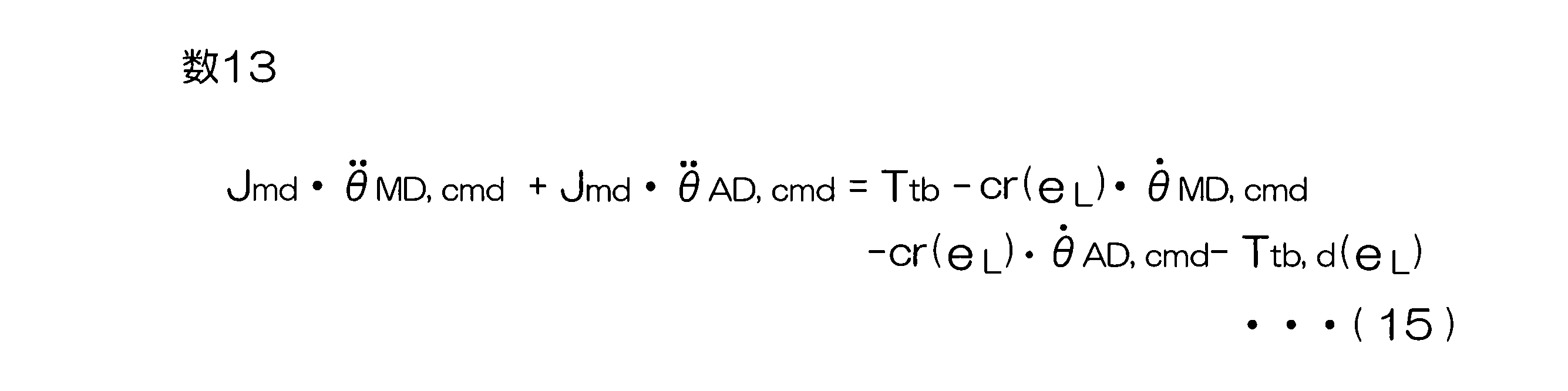
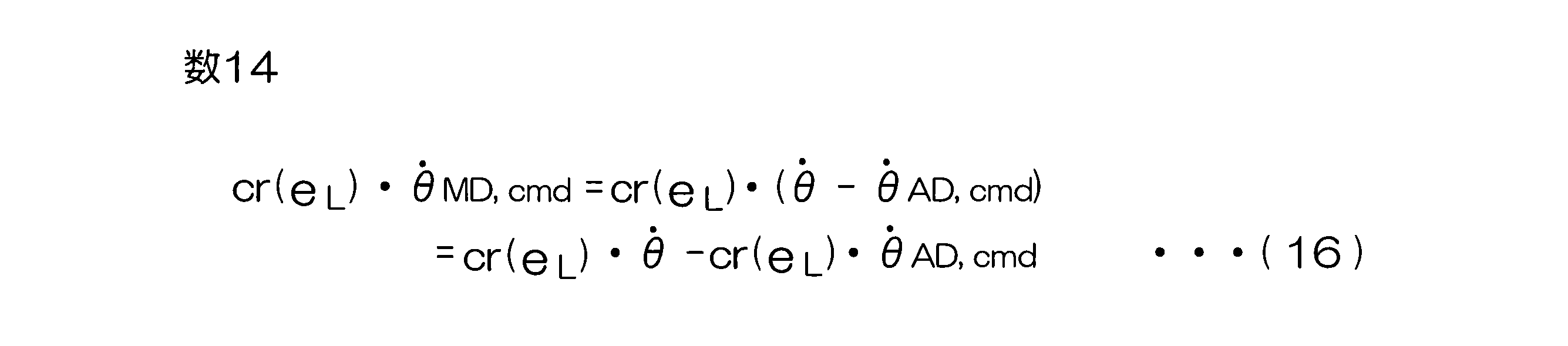
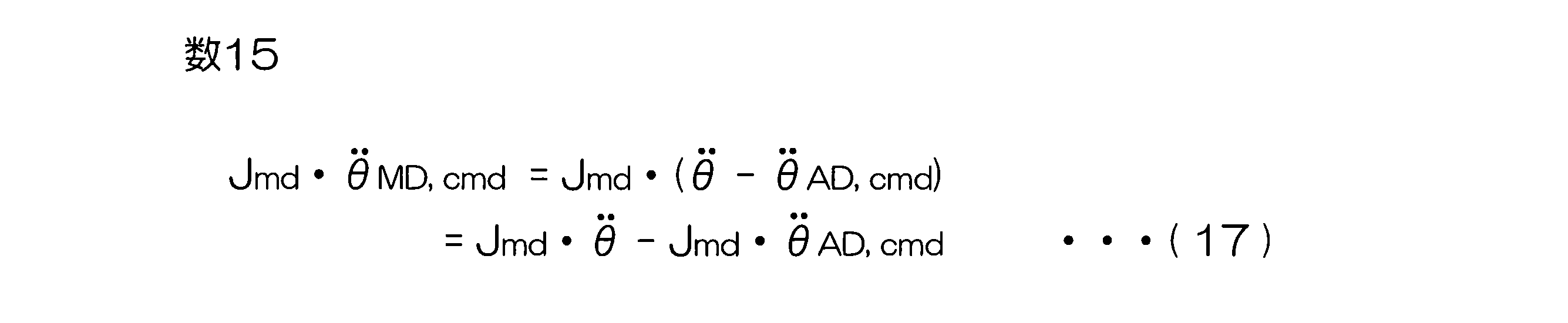

Claims (7)
- 操舵装置の電動モータを駆動制御するためのモータ制御装置であって、
前記操舵装置のリファレンスモデルの運動方程式を利用して、手動操舵指令値を生成する手動操舵指令値生成部と、
運転支援モード時に与えられる自動操舵指令値に前記手動操舵指令値を加算して、統合角度指令値を演算する統合角度指令値演算部と、
前記統合角度指令値に基づいて、舵角制御用の電動モータを角度制御する制御部と、
前記自動操舵指令値と実操舵角との角度偏差の時間微分値に応じて、前記運動方程式を変更する運動方程式設定部とを含む、モータ制御装置。 - 前記運動方程式は、路面反力特性係数を含んでおり、
前記運動方程式設定部は、前記運動方程式に含まれる路面反力特性係数のうちの少なくとも1つの路面反力特性係数の値を変更することにより、前記運動方程式を変更する、請求項1に記載のモータ制御装置。 - 前記運動方程式設定部は、第1の運動方程式と第2の運動方程式とを切り替えることにより、前記運動方程式を変更するように構成されており、
前記第1の運動方程式では、仮想ばね反力として、車両基準位置の走行車線に対する横位置に応じた目標仮想ばね反力が用いられ、
前記第2の運動方程式では、仮想ばね反力として、前記横位置にかかわらず一定値の仮想負荷ばね剛性係数を用いて設定される仮想ばね反力が用いられる、請求項1に記載のモータ制御装置。 - 前記運動方程式設定部は、車両基準位置の走行車線に対する横位置および前記角度偏差のうちのいずれか一方と、前記時間微分値とに基づいて、前記車両が逸脱側に向かう状態であるか、前記車両が逸脱回避側に向かう状態であるかを判定し、その判定結果に基づいて、前記運動方程式を変更するように構成されている、請求項1~3のいずれか一項に記載のモータ制御装置。
- 前記運動方程式設定部は、車両基準位置の走行車線に対する横位置および前記角度偏差のうちのいずれか一方と、前記時間微分値とに基づいて、前記車両が逸脱側に向かう状態であるか、前記車両が逸脱回避側に向かう状態であるかを判定し、前記車両が逸脱回避側に向かう状態では、前記車両が逸脱側に向かう状態に比べて、前記運動方程式に含まれる前記路面反力特性係数のうちの少なくとも1つの路面反力特性係数の値を小さくする、請求項2に記載のモータ制御装置。
- 前記運動方程式設定部は、車両基準位置の走行車線に対する横位置および前記角度偏差のうちのいずれか一方と、前記時間微分値とに基づいて、前記車両が逸脱側に向かう状態であるか、前記車両が逸脱回避側に向かう状態であるかを判定し、前記車両が逸脱側に向かう状態では、前記運動方程式に含まれる前記路面反力特性係数のうちの少なくとも1つの路面反力特性係数を、前記横位置に応じて変化させる、請求項2に記載のモータ制御装置。
- 前記運動方程式設定部は、前記時間微分値を用いて、前記車両が逸脱側に向かう状態であるか、前記車両が逸脱回避側に向かう状態であるかを判定し、前記車両が逸脱側に向かう状態では、前記運動方程式として前記第1の運動方程式を設定し、前記車両が逸脱回避側に向かう状態では、前記運動方程式として前記第2の運動方程式を設定する、請求項3に記載のモータ制御装置。
Priority Applications (3)
| Application Number | Priority Date | Filing Date | Title |
|---|---|---|---|
| CN202380078740.4A CN120187625A (zh) | 2022-11-14 | 2023-11-13 | 马达控制装置 |
| EP23891524.3A EP4620779A4 (en) | 2022-11-14 | 2023-11-13 | ENGINE CONTROL DEVICE |
| JP2024558856A JPWO2024106377A1 (ja) | 2022-11-14 | 2023-11-13 |
Applications Claiming Priority (2)
| Application Number | Priority Date | Filing Date | Title |
|---|---|---|---|
| JP2022181888 | 2022-11-14 | ||
| JP2022-181888 | 2022-11-14 |
Publications (1)
| Publication Number | Publication Date |
|---|---|
| WO2024106377A1 true WO2024106377A1 (ja) | 2024-05-23 |
Family
ID=91084419
Family Applications (1)
| Application Number | Title | Priority Date | Filing Date |
|---|---|---|---|
| PCT/JP2023/040764 Ceased WO2024106377A1 (ja) | 2022-11-14 | 2023-11-13 | モータ制御装置 |
Country Status (4)
| Country | Link |
|---|---|
| EP (1) | EP4620779A4 (ja) |
| JP (1) | JPWO2024106377A1 (ja) |
| CN (1) | CN120187625A (ja) |
| WO (1) | WO2024106377A1 (ja) |
Cited By (2)
| Publication number | Priority date | Publication date | Assignee | Title |
|---|---|---|---|---|
| WO2025220188A1 (ja) * | 2024-04-18 | 2025-10-23 | 株式会社ジェイテクト | 操舵制御システム |
| WO2025233992A1 (ja) * | 2024-05-07 | 2025-11-13 | 株式会社ジェイテクト | モータ制御装置 |
Citations (10)
| Publication number | Priority date | Publication date | Assignee | Title |
|---|---|---|---|---|
| JP2003016600A (ja) * | 2001-06-12 | 2003-01-17 | Hyundai Motor Co Ltd | 自動車の車線離脱防止システム及びその制御方法 |
| JP2006175957A (ja) * | 2004-12-21 | 2006-07-06 | Nissan Motor Co Ltd | 車線逸脱防止装置 |
| WO2009110151A1 (ja) * | 2008-03-04 | 2009-09-11 | 日産自動車株式会社 | 車線維持支援装置及び車線維持支援方法 |
| JP2019194059A (ja) * | 2018-04-27 | 2019-11-07 | 株式会社ジェイテクト | モータ制御装置 |
| JP2020019346A (ja) * | 2018-07-31 | 2020-02-06 | 株式会社ジェイテクト | モータ制御装置 |
| JP2022181888A (ja) | 2021-05-27 | 2022-12-08 | 貞夫 村松 | 飲料用容器 |
| WO2023286169A1 (ja) | 2021-07-13 | 2023-01-19 | 株式会社ジェイテクト | モータ制御装置 |
| JP2023048867A (ja) * | 2021-09-28 | 2023-04-07 | 株式会社ジェイテクト | モータ制御装置 |
| WO2023100369A1 (ja) * | 2021-12-03 | 2023-06-08 | 株式会社ジェイテクト | モータ制御装置 |
| WO2023144895A1 (ja) * | 2022-01-25 | 2023-08-03 | 株式会社ジェイテクト | モータ制御装置 |
Family Cites Families (2)
| Publication number | Priority date | Publication date | Assignee | Title |
|---|---|---|---|---|
| US10843727B2 (en) * | 2017-07-07 | 2020-11-24 | Jtekt Corporation | Steering apparatus |
| JP7316524B2 (ja) * | 2019-06-24 | 2023-07-28 | 株式会社ジェイテクト | 操舵角演算装置およびそれを利用したモータ制御装置 |
-
2023
- 2023-11-13 WO PCT/JP2023/040764 patent/WO2024106377A1/ja not_active Ceased
- 2023-11-13 CN CN202380078740.4A patent/CN120187625A/zh active Pending
- 2023-11-13 EP EP23891524.3A patent/EP4620779A4/en active Pending
- 2023-11-13 JP JP2024558856A patent/JPWO2024106377A1/ja active Pending
Patent Citations (10)
| Publication number | Priority date | Publication date | Assignee | Title |
|---|---|---|---|---|
| JP2003016600A (ja) * | 2001-06-12 | 2003-01-17 | Hyundai Motor Co Ltd | 自動車の車線離脱防止システム及びその制御方法 |
| JP2006175957A (ja) * | 2004-12-21 | 2006-07-06 | Nissan Motor Co Ltd | 車線逸脱防止装置 |
| WO2009110151A1 (ja) * | 2008-03-04 | 2009-09-11 | 日産自動車株式会社 | 車線維持支援装置及び車線維持支援方法 |
| JP2019194059A (ja) * | 2018-04-27 | 2019-11-07 | 株式会社ジェイテクト | モータ制御装置 |
| JP2020019346A (ja) * | 2018-07-31 | 2020-02-06 | 株式会社ジェイテクト | モータ制御装置 |
| JP2022181888A (ja) | 2021-05-27 | 2022-12-08 | 貞夫 村松 | 飲料用容器 |
| WO2023286169A1 (ja) | 2021-07-13 | 2023-01-19 | 株式会社ジェイテクト | モータ制御装置 |
| JP2023048867A (ja) * | 2021-09-28 | 2023-04-07 | 株式会社ジェイテクト | モータ制御装置 |
| WO2023100369A1 (ja) * | 2021-12-03 | 2023-06-08 | 株式会社ジェイテクト | モータ制御装置 |
| WO2023144895A1 (ja) * | 2022-01-25 | 2023-08-03 | 株式会社ジェイテクト | モータ制御装置 |
Non-Patent Citations (1)
| Title |
|---|
| See also references of EP4620779A1 |
Cited By (2)
| Publication number | Priority date | Publication date | Assignee | Title |
|---|---|---|---|---|
| WO2025220188A1 (ja) * | 2024-04-18 | 2025-10-23 | 株式会社ジェイテクト | 操舵制御システム |
| WO2025233992A1 (ja) * | 2024-05-07 | 2025-11-13 | 株式会社ジェイテクト | モータ制御装置 |
Also Published As
| Publication number | Publication date |
|---|---|
| JPWO2024106377A1 (ja) | 2024-05-23 |
| EP4620779A4 (en) | 2026-03-11 |
| EP4620779A1 (en) | 2025-09-24 |
| CN120187625A (zh) | 2025-06-20 |
Similar Documents
| Publication | Publication Date | Title |
|---|---|---|
| JP7236037B2 (ja) | 車両用操舵装置 | |
| EP3608203B1 (en) | Motor control apparatus | |
| JP7194326B2 (ja) | モータ制御装置 | |
| EP3626580B1 (en) | Motor control device and motor control method | |
| JP7769862B2 (ja) | モータ制御装置 | |
| JP7769889B2 (ja) | モータ制御装置 | |
| JP7780710B2 (ja) | モータ制御装置 | |
| WO2024106377A1 (ja) | モータ制御装置 | |
| JP7695632B2 (ja) | モータ制御装置 | |
| JP7681245B2 (ja) | 操舵装置 | |
| JP7769888B2 (ja) | モータ制御装置 | |
| JP7755798B2 (ja) | モータ制御装置 | |
| JP7818171B2 (ja) | モータ制御装置 | |
| EP4734360A1 (en) | Motor control device | |
| EP4734353A1 (en) | Motor control device | |
| JP7624148B2 (ja) | 操舵装置 | |
| EP4703240A1 (en) | Motor control device | |
| WO2024257466A1 (ja) | モータ制御装置 | |
| WO2024252630A1 (ja) | モータ制御装置 | |
| WO2024180745A1 (ja) | 操舵装置 | |
| WO2025233992A1 (ja) | モータ制御装置 | |
| JP2024176411A (ja) | モータ制御装置 |
Legal Events
| Date | Code | Title | Description |
|---|---|---|---|
| 121 | Ep: the epo has been informed by wipo that ep was designated in this application |
Ref document number: 23891524 Country of ref document: EP Kind code of ref document: A1 |
|
| WWE | Wipo information: entry into national phase |
Ref document number: 2024558856 Country of ref document: JP |
|
| WWE | Wipo information: entry into national phase |
Ref document number: 202380078740.4 Country of ref document: CN |
|
| WWE | Wipo information: entry into national phase |
Ref document number: 2023891524 Country of ref document: EP |
|
| NENP | Non-entry into the national phase |
Ref country code: DE |
|
| WWP | Wipo information: published in national office |
Ref document number: 202380078740.4 Country of ref document: CN |
|
| ENP | Entry into the national phase |
Ref document number: 2023891524 Country of ref document: EP Effective date: 20250616 |
|
| WWP | Wipo information: published in national office |
Ref document number: 2023891524 Country of ref document: EP |