WO2024252630A1 - モータ制御装置 - Google Patents
モータ制御装置 Download PDFInfo
- Publication number
- WO2024252630A1 WO2024252630A1 PCT/JP2023/021405 JP2023021405W WO2024252630A1 WO 2024252630 A1 WO2024252630 A1 WO 2024252630A1 JP 2023021405 W JP2023021405 W JP 2023021405W WO 2024252630 A1 WO2024252630 A1 WO 2024252630A1
- Authority
- WO
- WIPO (PCT)
- Prior art keywords
- command value
- torque
- steering
- vehicle
- torque command
- Prior art date
- Legal status (The legal status is an assumption and is not a legal conclusion. Google has not performed a legal analysis and makes no representation as to the accuracy of the status listed.)
- Ceased
Links
Images


Classifications
-
- B—PERFORMING OPERATIONS; TRANSPORTING
- B62—LAND VEHICLES FOR TRAVELLING OTHERWISE THAN ON RAILS
- B62D—MOTOR VEHICLES; TRAILERS
- B62D5/00—Power-assisted or power-driven steering
- B62D5/04—Power-assisted or power-driven steering electrical, e.g. using an electric servo-motor connected to, or forming part of, the steering gear
-
- B—PERFORMING OPERATIONS; TRANSPORTING
- B62—LAND VEHICLES FOR TRAVELLING OTHERWISE THAN ON RAILS
- B62D—MOTOR VEHICLES; TRAILERS
- B62D6/00—Arrangements for automatically controlling steering depending on driving conditions sensed and responded to, e.g. control circuits
Definitions
- This disclosure relates to a control device for an electric motor for steering angle control.
- Patent Document 1 discloses a motor control device that includes an assist torque command value setting unit that generates an assist torque command value using a torsion bar torque, a manual steering command value generation unit that generates a manual steering command value using the torsion bar torque and the assist torque command value, an integrated angle command value calculation unit that adds the manual steering command value to the automatic steering command value to calculate an integrated angle command value, and a switching unit that switches between a first control that controls the electric motor based only on the assist torque command value and a second control that controls the electric motor based on the integrated angle command value based on a switching signal.
- the objective of this disclosure is to provide a motor control device that can use a novel method to prevent the steering wheel from automatically rotating when the vehicle is stopped or the steering member is not being gripped and is in a hands-free state during driving assistance mode.
- One embodiment of the present disclosure provides a motor control device for controlling the drive of an electric motor of a steering device, the motor control device including: a first torque command value generation unit that generates a first torque command value using a target torque corresponding to the distance between the vehicle and a specified object in a driving assistance mode; a determination unit that determines whether an assistance stop condition is satisfied, that is, the vehicle is in a stopped state or the steering member is in a hands-off state in which it is not gripped; and a control unit that, in the driving assistance mode, drives and controls the electric motor based on the first torque command value if the assistance stop condition is not satisfied, and that drives and controls the electric motor based on a second torque command value that does not include the first torque command value if the assistance stop condition is satisfied.
- the steering wheel when in driving assistance mode, if the vehicle is stopped or the steering member is not being gripped and is in a hands-free state, the steering wheel can be prevented from being automatically rotated using a new method.
- FIG. 1 is a schematic diagram showing a schematic configuration of an electric power steering system to which a motor control device according to an embodiment of the present disclosure is applied.
- FIG. 2 is a block diagram for explaining the electrical configuration of the motor control ECU.
- FIG. 3 is a graph showing an example of setting the assist torque command value T as relative to the torsion bar torque T tb .
- FIG. 4 is a schematic diagram showing an example of a reference EPS model.
- FIG. 5 is a block diagram showing the configuration of the manual steering command value calculation unit.
- FIG. 6 is a block diagram showing the configuration of the angle control unit.
- FIG. 7 is a schematic diagram showing an example of the configuration of a physical model of an electric power steering system.
- FIG. 8 is a block diagram showing the configuration of the disturbance torque estimating unit.
- FIG. 9 is a schematic diagram showing the configuration of the torque control unit.
- FIG. 10 is a flowchart showing the procedure of the target virtual spring reaction force setting process executed by the target virtual spring reaction force setting unit in the parking assist mode.
- FIG. 11 is a graph showing an example of setting the magnitude A of the target virtual spring reaction force T tb,d relative to the distance D obs to the noted obstacle.
- FIG. 12 is a schematic diagram for explaining that the sign of the target virtual spring reaction force T tb,d (target driving assist force T pas ) is determined depending on the traveling direction of the vehicle and the position of the target obstacle.
- FIG. 13 is a flowchart showing the procedure of the switch control process executed by the host ECU in the parking assistance mode.
- FIG. 10 is a flowchart showing the procedure of the target virtual spring reaction force setting process executed by the target virtual spring reaction force setting unit in the parking assist mode.
- FIG. 11 is a graph showing an example of setting the magnitude A of the target virtual spring reaction force T tb,d relative to
- FIG. 14 is a block diagram showing a modified example of the motor control ECU.
- FIG. 15 is a flowchart showing the procedure of a target driving assist force setting process executed by the target driving assist force setting unit in the parking assist mode.
- FIG. 16 is a flowchart showing the procedure of the second switch control process executed by the host ECU in the parking assistance mode.
- One embodiment of the present disclosure provides a motor control device for driving and controlling an electric motor of a steering device, the motor control device including: a first torque command value generation unit that generates a first torque command value using a target torque corresponding to a distance between a vehicle and a specified object in a driving assistance mode; a determination unit that determines whether an assistance stop condition is satisfied, that is, the vehicle is in a stopped state or the steering member is in a let-go state where it is not being gripped; and a control unit that, in the driving assistance mode, drives and controls the electric motor based on the first torque command value if the assistance stop condition is not satisfied, and drives and controls the electric motor based on a second torque command value that does not include the first torque command value if the assistance stop condition is satisfied.
- the steering wheel when in driving assistance mode, if the vehicle is stopped or the steering member is not being gripped and is in a hands-free state, the steering wheel can be prevented from being automatically rotated using a new method.
- the first torque command value generation unit includes a manual steering command value calculation unit that calculates a manual steering command value using a torsion bar torque, and an angle control unit that calculates the first torque command value based on the manual steering command value
- the manual steering command value calculation unit is configured to calculate the manual steering command value using an equation of motion of a reference model of the steering device
- the manual steering command value calculation unit is configured to calculate the manual steering command value using the target torque as a virtual spring reaction force in the equation of motion
- the second torque command value is an assist torque command value generated using a torsion bar torque.
- the first torque command value is the target torque
- the second torque command value is an assist torque command value that is generated using the torsion bar torque
- the determination unit determines that the vehicle is stopped when the shift position is the parking position.
- the determination unit determines that the vehicle is stopped when the vehicle speed is equal to or less than a predetermined first threshold.
- the determination unit determines that the torsion bar is in a let-go state when the torsion bar torque is equal to or less than a predetermined second threshold value.
- FIG. 1 is a schematic diagram showing the general configuration of an electric power steering system to which a motor control device according to one embodiment of the present disclosure is applied.
- the electric power steering system 1 includes a steering wheel (handle) 2 as a steering member for steering the vehicle, a steering mechanism 4 that steers the steered wheels 3 in conjunction with the rotation of the steering wheel 2, and a steering assist mechanism 5 that assists the driver in steering.
- the steering wheel 2 and the steering mechanism 4 are mechanically connected via a steering shaft 6 and an intermediate shaft 7.
- the steering wheel 2 is an example of a "steering member" in this disclosure.
- the steering shaft 6 includes an input shaft 8 connected to the steering wheel 2 and an output shaft 9 connected to the intermediate shaft 7.
- the input shaft 8 and the output shaft 9 are connected via a torsion bar 10 so as to be capable of relative rotation.
- a torque sensor 12 is disposed near the torsion bar 10.
- the torque sensor 12 detects a torsion bar torque (steering torque) Ttb applied to the steering wheel 2 based on the amount of relative rotational displacement between the input shaft 8 and the output shaft 9.
- the torsion bar torque Ttb detected by the torque sensor 12 is detected as a positive value for torque for steering to the right and a negative value for torque for steering to the left, for example, and the magnitude of the torsion bar torque Ttb increases as the absolute value increases .
- the steering mechanism 4 is made up of a rack-and-pinion mechanism including a pinion shaft 13 and a rack shaft 14 as a steering shaft.
- the steered wheels 3 are connected to each end of the rack shaft 14 via tie rods 15 and knuckle arms (not shown).
- the pinion shaft 13 is connected to the intermediate shaft 7.
- the pinion shaft 13 rotates in conjunction with the steering of the steering wheel 2.
- a pinion 16 is connected to the tip of the pinion shaft 13.
- the rack shaft 14 extends linearly in the left-right direction of the vehicle.
- a rack 17 that meshes with the pinion 16 is formed in the middle of the rack shaft 14 in the axial direction.
- the pinion 16 and rack 17 convert the rotation of the pinion shaft 13 into axial movement of the rack shaft 14.
- the steered wheels 3 can be steered by moving the rack shaft 14 in the axial direction.
- the steering assist mechanism 5 includes an electric motor 18 for generating a steering assist force (assist torque), and a reducer 19 for amplifying the output torque of the electric motor 18 and transmitting it to the steering mechanism 4.
- the reducer 19 is made up of a worm gear mechanism including a worm gear 20 and a worm wheel 21 that meshes with the worm gear 20.
- the reducer 19 is housed in a gear housing 22 that serves as a transmission mechanism housing.
- the reduction ratio (gear ratio) of the reducer 19 is represented as N.
- the reduction ratio N is defined as the ratio ( ⁇ wg / ⁇ WW ) of the worm gear angle ⁇ wg , which is the rotation angle of the worm gear 20, to the worm wheel angle ⁇ ww , which is the rotation angle of the worm wheel 21.
- the worm gear 20 is rotated by the electric motor 18.
- the worm wheel 21 is connected to the output shaft 9 so that they can rotate together.
- the worm gear 20 When the worm gear 20 is driven to rotate by the electric motor 18, the worm wheel 21 is driven to rotate, and motor torque is applied to the steering shaft 6, causing the steering shaft 6 (output shaft 9) to rotate. The rotation of the steering shaft 6 is then transmitted to the pinion shaft 13 via the intermediate shaft 7. The rotation of the pinion shaft 13 is converted into axial movement of the rack shaft 14. This causes the steered wheels 3 to be steered. In other words, by driving the worm gear 20 to rotate by the electric motor 18, steering assistance by the electric motor 18 and steering of the steered wheels 3 are possible.
- the electric motor 18 is provided with a rotation angle sensor 23 for detecting the rotation angle of the rotor of the electric motor 18.
- the torque applied to the output shaft 9 includes the motor torque by the electric motor 18 and a disturbance torque Tlc other than the motor torque.
- the disturbance torque Tlc other than the motor torque includes a torsion bar torque Ttb , a road reaction torque (road load torque) Trl , a friction torque Tf, etc.
- the torsion bar torque Ttb is a torque applied to the output shaft 9 from the steering wheel 2 side due to a force applied to the steering wheel 2 by the driver, a force generated by steering inertia, or the like.
- the road reaction torque Trl is a torque applied to the output shaft 9 from the steered wheels 3 via the rack shaft 14 due to the self-aligning torque generated in the tires, forces generated by the suspension and tire/wheel alignment, frictional forces of the rack and pinion mechanism, etc.
- the vehicle is equipped with a CCD (Charge Coupled Device) camera 25 that photographs the road ahead in the direction of travel of the vehicle, a GPS (Global Positioning System) 26 for detecting the vehicle's position, a radar 27 for detecting road shapes and obstacles, an ultrasonic sensor 28 for measuring the distance from the vehicle to obstacles, a vehicle speed sensor 29 for detecting the vehicle speed V, etc.
- CCD Charge Coupled Device
- GPS Global Positioning System
- the vehicle is further equipped with two mode switches 31, 32 for manually switching between driving modes.
- the driving modes include a manual driving mode in which steering is performed manually, and a driving assistance mode in which driving assistance control is performed.
- the CCD camera 25, GPS 26, radar 27, ultrasonic sensor 28, vehicle speed sensor 29, etc. are connected to a host ECU (Electronic Control Unit) 201 for driving assistance control. Based on the information obtained from the CCD camera 25, GPS 26, radar 27, ultrasonic sensor 28, vehicle speed sensor 29, etc., the host ECU 201 performs surrounding environment recognition, vehicle position estimation, route planning, etc., and determines control target values for steering and drive actuators.
- ECU Electronic Control Unit
- the driving assistance control is parking assistance control that assists in parking. Therefore, in this embodiment, the driving modes include a "manual driving mode” in which steering is performed by manual driving, and a “parking assistance mode” in which parking assistance control is performed.
- the host ECU 201 sets the driving mode based on the operation of the first mode switch 31 and the second mode switch 32. Specifically, when the first mode switch 31 is operated, the host ECU 201 sets the driving mode to the manual driving mode. When the second mode switch 32 is operated, the host ECU 201 sets the driving mode to the parking assistance mode.
- the host ECU 201 sets a switch control signal SW cont for controlling the first switch 55 (see FIG. 2) and the second switch 56 provided on the motor control ECU 202 side.
- the switch control signal SW cont takes a value of 0 or 1.
- the host ECU 201 sets the switch control signal SW cont by performing a switch control process described later.
- the host ECU 201 is an example of a "determination unit" in this disclosure.
- the obstacle that is predicted to be most likely to cause a collision with the vehicle in parking assistance mode will be referred to as the "obstacle of interest.”
- the host ECU 201 When the driving mode is the parking assistance mode, the host ECU 201 outputs a distance (absolute value) D obs from the vehicle to the noted obstacle, a traveling direction signal S dir indicating whether the vehicle is moving forward or backward, and an obstacle position signal P obs indicating whether the noted obstacle is on the right or left side of a straight line that includes the vehicle width center line as a part when viewed from the rear of the vehicle.
- the heading signal S dir in this embodiment takes the value 0 or 1.
- the obstacle position signal P obs takes a value of 0 or 1.
- the switch control signal SW cont the distance D obs from the vehicle to the target obstacle, the traveling direction signal S dir , the obstacle position signal P obs and the vehicle speed V are provided to the motor control ECU 202 via the in-vehicle network.
- the torsion bar torque T tb detected by the torque sensor 12 and the output signal of the rotation angle sensor 23 are input to the motor control ECU 202.
- the motor control ECU 202 controls the electric motor 18 based on these input signals and information provided from the higher-level ECU 201.
- the torsion bar torque T tb is also provided from the motor control ECU 202 to the higher-level control ECU 201 via the in-vehicle network.
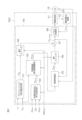
- FIG. 2 is a block diagram illustrating the electrical configuration of the motor control ECU 202.
- the motor control ECU 202 includes a microcomputer 50, a drive circuit (inverter circuit) 41 controlled by the microcomputer 50 and supplying power to the electric motor 18, and a current detection circuit 42 for detecting the current flowing through the electric motor 18 (hereinafter referred to as "motor current I m ").
- the microcomputer 50 is equipped with a CPU and memory (ROM, RAM, non-volatile memory, etc.), and functions as multiple function processing units by executing a predetermined program.
- the multiple function processing units include an assist torque command value setting unit 51, a target virtual spring reaction force setting unit 52, a manual steering command value calculation unit 53, an angle control unit 54, a first switch 55, a second switch 56, an adder 57, and a torque control unit (current control unit) 58.
- the assist torque command value setting unit 51 sets an assist torque command value T as which is a target value of the assist torque required for manual operation.
- the assist torque command value T as may be referred to as an “assist torque command value T as for manual operation.”
- the assist torque command value setting unit 51 sets the assist torque command value T as based on the torsion bar torque T tb detected by the torque sensor 12.
- FIG. 3 is a graph showing an example of setting the assist torque command value T as relative to the torsion bar torque T tb .
- the assist torque command value T as is set to a positive value when a steering assist force for steering in the right direction is to be generated from the electric motor 18, and is set to a negative value when a steering assist force for steering in the left direction is to be generated from the electric motor 18.
- the assist torque command value T as is positive for a positive value of the torsion bar torque T tb , and is negative for a negative value of the torsion bar torque T tb .
- the assist torque command value T as is set so that its absolute value increases as the absolute value of the torsion bar torque T tb increases, and is set so that its absolute value decreases as the vehicle speed V increases.
- the assist torque command value setting unit 51 may calculate the assist torque command value T as by multiplying the torsion bar torque T tb by a preset constant.
- the target virtual spring reaction force setting unit 52 sets a target virtual spring reaction force T tb,d having a magnitude according to the distance Dobs from the vehicle to the noted obstacle, based on the distance Dobs from the vehicle to the noted obstacle, the traveling direction signal S dir, and the obstacle position signal Pobs provided by the upper ECU 201.
- the target virtual spring reaction force setting unit 52 sets the target virtual spring reaction force T tb,d by executing a target virtual spring reaction force setting process.
- the target virtual spring reaction force setting process will be described in detail later.
- the target virtual spring reaction force T tb,d is an example of a "target torque" in the present disclosure.
- the manual steering command value calculation unit 53 is provided to set a steering angle (more precisely, a rotation angle ⁇ c of the output shaft 9) corresponding to the steering wheel operation as a manual steering command value ⁇ md when the driver operates the steering wheel 2 in the parking assist mode.
- the manual steering command value calculation unit 53 generates the manual steering command value ⁇ md using the torsion bar torque T tb detected by the torque sensor 12 and the target virtual spring reaction force T tb,d set by the target virtual spring reaction force setting unit 52.
- the manual steering command value ⁇ md is represented by the amount of rotation (rotation angle) from the neutral position of the output shaft 9, the amount of rotation from the neutral position in the right steering direction is represented as a positive value, and the amount of rotation from the neutral position in the left steering direction is represented as a negative value. Details of the manual steering command value calculation unit 53 will be described later.
- the angle control unit 54 calculates a manual steering torque command value Tmd corresponding to the manual steering command value ⁇ md based on the manual steering command value ⁇ md .
- the manual steering torque command value Tmd is an example of a "first torque command value” in the present disclosure.
- the manual steering command value calculation unit 53 and the angle control unit 54 are an example of a "first torque command value generation unit” in the present disclosure. Details of the angle control unit 54 will be described later.
- the motor torque command value T m,cmd which is the output of the adding unit 57 , is given to a torque control unit 58 .
- the torque control unit 58 drives the drive circuit 41 so that the motor torque of the electric motor 18 approaches the motor torque command value Tm,cmd .
- the torque control unit 58 will be described in detail later.
- the first switch 55, the second switch 56, the adder 57, and the torque control unit 58 are an example of a "control unit" in this disclosure.
- the manual steering command value calculation unit 53 will now be explained in detail.
- the manual steering command value generating unit generates the manual steering command value ⁇ md by using the reference EPS model of Fig. 4.
- the reference EPS model of Fig. 4 is an example of the "reference model of the steering device" of the present disclosure.
- This reference EPS model is a single inertia model including a lower column.
- the lower column corresponds to the output shaft 9 and the worm wheel 21.
- this model is only an example, and an inertia model including a configuration other than the above (for example, a rack bar, etc.) may be used.
- Jmd is the inertia of the lower column (hereinafter referred to as "column inertia")
- ⁇ col is the rotation angle of the lower column
- Ttb is the torsion bar torque.
- the lower column is supplied with a torsion bar torque Ttb , a torque N ⁇ Tm acting on the output shaft 9 from the electric motor 18, and a road reaction torque (virtual reaction force) Trl .
- the road surface reaction torque T rl is expressed by the following equation (1) using the spring constant kmd of the virtual spring and the viscous damping coefficient cmd of the virtual damper.
- k md and the viscous damping coefficient c md are obtained in advance by experiment, analysis, etc.
- k md ⁇ col may be referred to as a virtual spring reaction force
- c md (d ⁇ col /dt) may be referred to as a virtual damper reaction force.
- J md ⁇ d 2 ⁇ col /dt 2 is the moment of inertia acting on the lower column.
- the manual steering command value generating unit substitutes the torsion bar torque Ttb detected by the torque sensor 12 into Ttb , substitutes the assist torque command value Tas set by the assist torque command value setting unit 51 into Tm , and calculates the rotation angle ⁇ col of the lower column by solving the differential equation of equation (2).Then, the manual steering command value generating unit generates the obtained rotation angle ⁇ col of the lower column as the manual steering command value ⁇ md.
- the method of setting the manual steering command value ⁇ md in this manner is referred to as a comparison method.
- the equation of motion of formula (2) is equivalent to an equation of motion in which T m is replaced with T as and ⁇ col is replaced with ⁇ md .
- the manual steering command value calculation unit 53 calculates the manual steering command value ⁇ md by utilizing the equation of motion (2) of the reference EPS model described above. Specifically, in this embodiment, the manual steering command value calculation unit 53 calculates the manual steering command value ⁇ md based on an equation of motion obtained by modifying the equation of motion (2) of the reference EPS model described above.
- FIG. 5 is a block diagram showing the configuration of the manual steering command value calculation unit 53.
- Jmd is the column inertia
- s is a differential operator
- ⁇ md is a manual steering command value, which corresponds to the rotation angle ⁇ col of the lower column in the comparison method
- cmd is a viscous damping coefficient of the virtual damper, which is obtained in advance by experiments, analyses, etc.
- the manual steering command value calculation unit 53 includes an addition/subtraction unit 101, an inertia division unit 102, a first integration unit 103, a second integration unit 104, and a virtual damper reaction force calculation unit 105.
- the addition/subtraction unit 101 receives as input the torsion bar torque T tb , the target virtual spring reaction force T tb,d , and the virtual damper reaction force c md ⁇ d ⁇ md /dt provided by a virtual damper reaction force calculation unit 105 .
- the inertia division unit 102 divides the moment of inertia Jmd ⁇ d2 ⁇ md / dt2 calculated by the addition/subtraction unit 101 by the column inertia Jmd to calculate a second-order differential value d2 ⁇ md / dt2 of the manual steering command value ⁇ md .
- the first integration unit 103 calculates a first-order differential value d ⁇ md /dt of the manual steering command value ⁇ md by integrating a second-order differential value d 2 ⁇ md /dt 2 of the manual steering command value ⁇ md .
- the second integral unit 104 calculates the manual steering command value ⁇ md by integrating the first-order differential value d ⁇ md /dt of the manual steering command value ⁇ md .
- This manual steering command value ⁇ md is output from the manual steering command value calculation unit 53.
- the virtual damper reaction force calculation unit 105 calculates a virtual damper reaction force c md ⁇ d ⁇ md /dt by multiplying the first-order differential value d ⁇ md /dt of the manual steering command value ⁇ md calculated by the first integration unit 103 by a viscous damping coefficient c md .
- This virtual damper reaction force c md ⁇ d ⁇ md / dt is fed back to the addition and subtraction unit 101.
- the manual steering command value calculation unit 53 calculates the manual steering command value ⁇ md based on the equation of motion shown in the following equation (3).
- J md ⁇ d 2 ⁇ md /dt 2 is the moment of inertia
- c md ⁇ d ⁇ md /dt is the virtual damper reaction force
- T tb,d is a target virtual spring reaction force having a magnitude according to the distance D obs from the vehicle to the obstacle of interest.
- the manual steering command value calculation unit 53 may calculate N ⁇ T as by multiplying the assist torque command value T as by the reduction ratio N, and provide the obtained N ⁇ T as to the addition/subtraction unit 101.
- the addition/subtraction unit 101 subtracts the virtual damper reaction force c md ⁇ d ⁇ md /dt and the target virtual spring reaction force T tb,d from a value obtained by adding N ⁇ T as to the torsion bar torque T tb .
- the manual steering command value calculation unit 53 calculates the manual steering command value ⁇ md based on the equation of motion in which N ⁇ T as is added to the right side of the above formula (3).
- FIG. 6 is a block diagram showing the configuration of the angle control unit 54.
- the angle control unit 54 calculates a manual steering torque command value Tmd based on the manual steering command value ⁇ md .
- the angle control unit 54 includes a low-pass filter (LPF) 61, a feedback control unit 62, a feedforward control unit 63, a disturbance torque estimation unit 64, a torque addition unit 65, a disturbance torque compensation unit 66, a first reduction gear ratio division unit 67, a reduction gear ratio multiplication unit 68, a rotation angle calculation unit 69, and a second reduction gear ratio division unit 70.
- LPF low-pass filter
- the reduction ratio multiplication unit 68 multiplies the motor torque command value Tm,cmd calculated by the addition unit 57 (see FIG. 2) by the reduction ratio N of the reducer 19, thereby converting the motor torque command value Tm,cmd into an output shaft torque command value N ⁇ Tm,cmd acting on the output shaft 9 (worm wheel 21).
- the rotation angle calculation unit 69 calculates a rotor rotation angle ⁇ m of the electric motor 18 based on the output signal of the rotation angle sensor 23.
- the second reduction ratio division unit 70 converts the rotor rotation angle ⁇ m into a rotation angle (actual steering angle) ⁇ c of the output shaft 9 by dividing the rotor rotation angle ⁇ m calculated by the rotation angle calculation unit 69 by the reduction ratio N.
- the steering angle ⁇ c is represented by the amount of rotation (rotation angle) from the neutral position of the output shaft 9, where the amount of rotation from the neutral position in the right steering direction is represented as a positive value, and the amount of rotation from the neutral position in the left steering direction is represented as a negative value.
- the low-pass filter 61 performs low-pass filtering on the manual steering command value ⁇ md .
- the manual steering command value ⁇ mdl after the low-pass filtering is provided to a feedback control unit 62 and a feedforward control unit 63.
- the low-pass filter 61 does not necessarily have to be provided.
- the feedback control unit 62 is provided to bring the steering angle estimated value ⁇ calculated by the disturbance torque estimation unit 64 closer to the manual steering command value ⁇ mdl after low-pass filter processing.
- the feedback control unit 62 includes an angle deviation calculation unit 62A and a PD control unit 62B.
- the angle deviation calculation unit 62A may calculate the deviation ( ⁇ mdl - ⁇ c ) between the manual steering command value ⁇ mdl and the steering angle ⁇ c calculated by the second reduction ratio division unit 70 as the angle deviation ⁇ .
- the PD control unit 62B performs a PD calculation (proportional differential calculation) on the angle deviation ⁇ calculated by the angle deviation calculation unit 62A to calculate a feedback control torque Tfb .
- the feedback control torque Tfb is provided to a torque addition unit 65.
- the feedforward control unit 63 is provided to improve the control response by compensating for a delay in response due to the inertia of the electric power steering system 1.
- the feedforward control unit 63 includes an angular acceleration calculation unit 63A and an inertia multiplication unit 63B.
- the angular acceleration calculation unit 63A calculates a target angular acceleration d 2 ⁇ mdl /dt 2 by second-order differentiation of the manual steering command value ⁇ mdl .
- the inertia J is obtained, for example, from a physical model (see FIG. 7) of the electric power steering system 1, which will be described later.
- the feedforward control torque Tff is provided to the torque addition unit 65 as an inertia compensation value.
- the torque addition unit 65 calculates a basic torque command value ( Tfb + Tff ) by adding the feedforward control torque Tff to the feedback control torque Tfb .
- the disturbance torque estimating unit 64 is provided to estimate a nonlinear torque (disturbance torque: torque other than motor torque) that occurs as a disturbance in the plant (the control target of the electric motor 18).
- the disturbance torque estimating unit 64 estimates the disturbance torque (disturbance load) T lc , the steering angle ⁇ , and the steering angle differential value (angular velocity) d ⁇ c /dt based on the output shaft torque command value N ⁇ T m,cmd and the steering angle ⁇ c .
- the estimated values of the disturbance torque T lc , the steering angle ⁇ c, and the steering angle differential value (angular velocity) d ⁇ c /dt are represented by ⁇ T lc , ⁇ c, and d ⁇ c /dt, respectively.
- the details of the disturbance torque estimating unit 64 will be described later.
- the disturbance torque estimated value ⁇ Tlc calculated by the disturbance torque estimating section 64 is provided as a disturbance torque compensation value to a disturbance torque compensating section 66.
- the steering angle estimated value ⁇ ⁇ c calculated by the disturbance torque estimating section 64 is provided to an angle deviation calculating section 62A.
- the manual steering torque command value Tmdo is provided to a first reduction ratio division unit 67.
- the first reduction ratio division unit 67 calculates a manual steering torque command value Tmd (torque command value for the electric motor 18) by dividing the manual steering torque command value Tmdo by the reduction ratio N.
- This manual steering torque command value Tmd is provided to the first switch 55 (see FIG. 2).
- the disturbance torque estimation unit 64 will be described in detail.
- the disturbance torque estimation unit 64 is composed of a disturbance observer that estimates the disturbance torque T lc , the steering angle ⁇ c and the angular velocity d ⁇ c /dt using, for example, a physical model 300 of the electric power steering system 1 shown in FIG.
- This physical model 300 includes a plant (an example of a motor-driven object) 301 including an output shaft 9 and a worm wheel 21 fixed to the output shaft 9.
- a torsion bar torque Ttb is applied to the plant 301 from the steering wheel 2 via the torsion bar 10, and a road reaction torque Trl is applied from the steered wheels 3 side.
- an output shaft torque command value N ⁇ T m,cmd is applied to the plant 301 via the worm gear 20 , and a friction torque T f is applied due to friction between the worm wheel 21 and the worm gear 20 .
- Tlc indicates a disturbance torque other than the motor torque applied to the plant 301.
- the disturbance torque Tlc is shown as the sum of the torsion bar torque Ttb , the road surface reaction torque Trl, and the friction torque Tf , but in reality, the disturbance torque Tlc includes torques other than these.
- x is a state variable vector
- u1 is a known input vector
- u2 is an unknown input vector
- y is an output vector (measured value).
- A is a system matrix
- B1 is a first input matrix
- B2 is a second input matrix
- C is an output matrix
- D is a direct feedthrough matrix.
- the state equation is expanded to a system including the unknown input vector u2 as one of the states.
- the state equation of the expanded system (expanded state equation) is expressed by the following equation (6).
- x e is a state variable vector of the extended system, and is expressed by the following formula (7).
- a e is the system matrix of the extended system
- B e is the known input matrix of the extended system
- C e is the output matrix of the extended system.
- ⁇ xe represents an estimated value of xe .
- L is the observer gain.
- ⁇ y represents an estimated value of y.
- ⁇ xe is expressed by the following equation (9).
- ⁇ c is an estimate of ⁇ c and ⁇ T lc is an estimate of T lc .
- the disturbance torque estimation unit 64 calculates the state variable vector ⁇ x e based on the above equation (8).
- FIG. 8 is a block diagram showing the configuration of the disturbance torque estimation unit 64.
- the disturbance torque estimation unit 64 includes an input vector input unit 81, an output matrix multiplication unit 82, a first adder unit 83, a gain multiplication unit 84, an input matrix multiplication unit 85, a system matrix multiplication unit 86, a second adder unit 87, an integrator unit 88, and a state variable vector output unit 89.
- the output shaft torque command value N ⁇ T m,cmd calculated by the reduction ratio multiplication section 68 (see FIG. 6) is given to an input vector input section 81.
- the input vector input section 81 outputs an input vector u1 .
- the output of the integrator 88 becomes the state variable vector ⁇ x e (see equation (9) above).
- an initial value is given as the state variable vector ⁇ x e .
- the initial value of the state variable vector ⁇ x e is, for example, 0.
- the system matrix multiplication unit 86 multiplies the state variable vector ⁇ xe by the system matrix A e .
- the output matrix multiplication unit 82 multiplies the state variable vector ⁇ xe by the output matrix C e .
- the gain multiplier 84 multiplies the output (y - ⁇ y) of the first adder 83 by the observer gain L (see equation (8) above).
- the input matrix multiplication unit 85 multiplies the input vector u 1 output from the input vector input unit 81 by the input matrix B e .
- the second adder 87 adds the output (B e ⁇ u 1 ) of the input matrix multiplication unit 85, the output (A e ⁇ ⁇ x e ) of the system matrix multiplication unit 86, and the output (L(y- ⁇ y)) of the gain multiplication unit 84 to calculate a differential value d ⁇ x e /dt of the state variable vector.
- the integrator 88 integrates the output (d ⁇ x e /dt) of the second adder 87 to calculate the state variable vector ⁇ x e .
- the state variable vector output unit 89 calculates a disturbance torque estimate value ⁇ T lc , a steering angle estimate value ⁇ c, and an angular velocity estimate value d ⁇ c /dt based on the state variable vector ⁇ x e .
- a typical disturbance observer consists of an inverse model of the plant and a low-pass filter.
- the equation of motion of the plant is expressed by equation (4) as described above. Therefore, the inverse model of the plant is expressed by the following equation (10).
- the inputs to a general disturbance observer are J ⁇ d2 ⁇ c / dt2 and N ⁇ Tm ,cmd , and since the second-order differential value of the steering angle ⁇ c is used, it is significantly affected by noise from the rotation angle sensor 23.
- the extended state observer of the above-mentioned embodiment estimates the disturbance torque in an integral manner, so that it is possible to reduce the influence of noise due to differentiation.
- a general disturbance observer consisting of an inverse model of the plant and a low-pass filter may be used as the disturbance torque estimation unit 64.
- FIG. 9 is a schematic diagram showing the configuration of the torque control unit 58.
- the torque control unit 58 (see FIG. 2) includes a motor current command value calculation unit 91, a current deviation calculation unit 92, a PI control unit 93, and a PWM (Pulse Width Modulation) control unit 94.
- the motor current command value calculation unit 91 calculates the motor current command value I m,cmd by dividing the motor torque command value T m,cmd calculated by the adder 57 (see FIG. 2) by the torque constant Kt of the electric motor 18 .
- the PI control unit 93 performs a PI calculation (proportional integral calculation) on the current deviation ⁇ I calculated by the current deviation calculation unit 92 to generate a drive command value for guiding the motor current I m flowing through the electric motor 18 to the motor current command value I m,cmd .
- the PWM control unit 94 generates a PWM control signal with a duty ratio corresponding to the drive command value, and supplies it to the drive circuit 41. As a result, power corresponding to the drive command value is supplied to the electric motor 18.
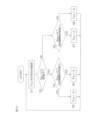
- FIG. 10 is a flowchart showing the steps of the target virtual spring reaction force setting process executed by the target virtual spring reaction force setting unit 52 in the parking assistance mode.
- the target virtual spring reaction force setting unit 52 sets a magnitude A (A ⁇ 0) of a target virtual spring reaction force T tb,d based on a distance D obs from the vehicle to a target obstacle provided by the host ECU 201 (step S1).
- FIG. 11 is a graph showing an example of setting the magnitude A of the target virtual spring reaction force T tb,d versus the distance D obs from the vehicle to the obstacle of interest.
- the magnitude A of the target virtual spring reaction force T tb,d is the maximum value A max .
- the magnitude A of the target virtual spring reaction force T tb,d is 0.
- the magnitude A of the target virtual spring reaction force T tb,d is set to decrease from the maximum value A max to 0 as the distance D obs increases.
- the magnitude A of the target virtual spring reaction force T tb,d is set to the maximum value A max only when the distance D obs is 0.
- the magnitude A of the target virtual spring reaction force T tb,d for a range of the distance D obs from 0 to a predetermined value greater than 0 may be set to the maximum value A max .
- the threshold value Dth is set to a value that is considered to be unnecessary to generate a driving support force for avoiding a collision with the noted obstacle if the distance Dobs from the vehicle to the noted obstacle is equal to or greater than the threshold value Dth .
- the threshold value Dth is set to a value that is considered to be unnecessary to generate a driving support force for avoiding a collision with the noted obstacle if the distance Dobs from the vehicle to the noted obstacle is less than the threshold value Dth .
- the target virtual spring reaction force setting unit 52 determines whether or not the traveling direction signal S dir is 0 (step S2). If the traveling direction signal S dir is 0 (step S2: YES), that is, if the traveling direction is forward, the target virtual spring reaction force setting unit 52 determines whether or not the obstacle position signal P obs is 0 (step S3).
- step S3 YES
- the target virtual spring reaction force setting unit 52 sets A set in step S1 as the target virtual spring reaction force T tb,d (step S4). That is, the target virtual spring reaction force setting unit 52 sets the target virtual spring reaction force T tb,d to a positive value. Then, the target virtual spring reaction force setting unit 52 returns to step S1.
- step S3 when it is determined that the obstacle position signal P obs is 1 (step S3: NO), that is, when the noted obstacle is present on the left side when viewed from the rear to the front of the vehicle (left side in the forward direction), the target virtual spring reaction force setting unit 52 sets the value -A obtained by adding a negative sign to the value A set in step S1 as the target virtual spring reaction force T tb,d (step S5). In other words, the target virtual spring reaction force setting unit 52 sets the value of the target virtual spring reaction force T tb,d to a negative value. Then, the target virtual spring reaction force setting unit 52 returns to step S1.
- step S2 when it is determined that the traveling direction signal S_dir is 1 (step S2: NO), that is, when the traveling direction is reverse, the target virtual spring reaction force setting unit 52 determines whether or not the obstacle position signal P_obs is 0 (step S6).
- step S6 When the obstacle position signal P obs is 0 (step S6: YES), that is, when the target obstacle is present on the right side (left side in the backward traveling direction) when viewed from the rear of the vehicle to the front, the target virtual spring reaction force setting unit 52 sets A set in step S1 as the target virtual spring reaction force T tb,d (step S7). That is, the target virtual spring reaction force setting unit 52 sets the target virtual spring reaction force T tb,d to a positive value. Then, the target virtual spring reaction force setting unit 52 returns to step S1.
- step S6 when it is determined that the obstacle position signal P obs is 1 (step S6: NO), that is, when the noted obstacle is present on the left side when viewed from the rear to the front of the vehicle (the right side in the backward traveling direction), the target virtual spring reaction force setting unit 52 sets the value -A obtained by adding a negative sign to the value A set in step S1 as the target virtual spring reaction force T tb,d (step S8). In other words, the target virtual spring reaction force setting unit 52 sets the value of the target virtual spring reaction force T tb,d to a negative value. Then, the target virtual spring reaction force setting unit 52 returns to step S1.
- FIG. 13 is a flowchart showing the steps of the switch control process executed by the host ECU 201 in parking assistance mode.
- the host ECU 201 sets the switch control signal SW_cont to 0 (step S11). This turns off the first switch 55 and turns on the second switch 56. This causes the electric motor 18 to be driven and controlled based on the assist torque command value T_as .
- the host ECU 201 obtains a distance D obs from the vehicle to the noted obstacle (step S12), and determines whether the obtained distance D obs is less than a predetermined threshold D th (D th >0) (step S13).
- step S13 determines whether the assist force stop condition is met, that is, the vehicle is stopped or the steering member is not gripped and is in a let-go state (step S14).
- the host ECU 201 determines that the support force stop condition is met when it is determined that the vehicle is stopped, when it is determined that the vehicle is in a hands-off state, or when it is determined that the vehicle is stopped and hands-off.
- the host ECU 201 determines that the support force stop condition is not met when it is determined that the vehicle is not stopped and hands-off.
- the determination of whether the vehicle is stopped may be made based on the shift position. Specifically, the vehicle may be determined to be stopped when the shift position is the parking position.
- the determination of whether the vehicle is stopped may be made based on the vehicle speed V. Specifically, the vehicle may be determined to be stopped when the vehicle speed V is equal to or lower than a predetermined speed.
- the determination of whether the vehicle is stopped may also be made based on the relative speed between the obstacle and the vehicle obtained by clearance sonar, radar, or image recognition. Specifically, the vehicle may be determined to be stopped when the relative speed between the obstacle and the vehicle is equal to or less than a predetermined relative speed. The determination of whether the vehicle is stopped may also be made by a known method other than these methods.
- the determination as to whether or not the hand is released is performed based on the torsion bar torque Tth . Specifically, when the torsion bar torque Tth is equal to or less than a predetermined value, the hand is released.
- the determination as to whether or not the hand is released may be performed by a known method other than this method.
- step S14 NO
- the host ECU 201 sets the switch control signal SW cont to 1 (step S15).
- the first switch 55 is turned on and the second switch 56 is turned off.
- the electric motor 18 is controlled to be driven based on the manual steering torque command value T md .
- a driving assist force (driving assist force for avoiding a collision with the noted obstacle) based on the target virtual spring reaction force Ttb,d set by the target virtual spring reaction force setting unit 52 is applied.
- This driving assist force causes the vehicle to be steered in a direction away from the noted obstacle.
- step S13 If it is determined in step S13 that the distance D obs is equal to or greater than a predetermined threshold value D th (step S13: NO) or if it is determined in step S14 that the assist force stop condition is satisfied (step S14: YES), the host ECU 201 sets the switch control signal SW cont to 0 (step S16). This turns off the first switch 55 and turns on the second switch 56. This causes the electric motor 18 to be driven and controlled based on the assist torque command value T as .
- the driving assistance force based on the target virtual spring reaction force T tb,d does not act.
- the driving assistance force based on the target virtual spring reaction force T tb,d does not act.
- the steering wheel 2 can be prevented from being automatically rotated.
- step S16 the host ECU 201 returns to step S12.
- the switch control signal SW cont is set to 0, so that the first switch 55 is turned off and the second switch 56 is turned on. As a result, the electric motor 18 is controlled to be driven based on the assist torque command value T as .
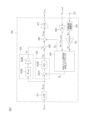
- FIG. 14 is a block diagram showing a modified example of the motor control ECU.
- the parts corresponding to those in FIG. 2 are denoted by the same reference numerals as in FIG. 2.
- the switch control signal SW cont the distance Dobs from the vehicle to the noted obstacle, the obstacle position signal Pobs , the traveling direction signal Sdir , and the vehicle speed V are transmitted from the host ECU 201 to the motor control ECU 202A.
- the host ECU 201 also performs a switch control process (hereinafter referred to as "second switch control process") for controlling the on/off of the switch 55A in Fig. 14.
- the second switch control process will be described in detail later.
- the microcomputer 50 in the motor control ECU 202A includes, as multiple functional processing units, an assist torque command value setting unit 51, a target driving assist force setting unit 52A, a switch 55A, an adder 57A, and a torque control unit (current control unit) 58.
- the assist torque command value setting unit 51 and the torque control unit 58 are similar to the assist torque command value setting unit 51 and the torque control unit 58 in FIG. 2, respectively, and therefore will not be described.
- the assist torque command value T as set by the assist torque command value setting section 51 is provided to an adding section 57A.
- the target driving support force setting unit 52A sets a target driving support force Tpas for parking support control based on a distance Dobs from the vehicle to the target obstacle, an obstacle position signal Pobs , and a traveling direction signal Sdir provided from the upper ECU 201 during the parking support mode.
- the target driving support force setting unit 52A executes a target driving support force setting process for setting the target driving support force Tpas .
- the target driving support force Tpas is an example of a "target torque” and a "first torque command value" in the present disclosure.
- the target driving support force setting unit 52A is an example of a "first torque command value generating unit" in the present disclosure. The target driving support force setting process will be described in detail later.
- the target driving assist force Tpas set by the target driving assist force setting unit 52A is applied to the switch 55A.
- the host ECU 201 sets the switch control signal SW cont to 0.
- the driving mode is the parking assistance mode
- the host ECU 201 sets the switch control signal SW cont by a second switch control process described later.
- the motor torque command value T m,cmd which is the output of the adding section 57A, is given to a torque control section 58 .
- Switch 55A, adder 57A, and torque control unit 58 are an example of a “control unit" in this disclosure.
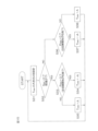
- FIG. 15 is a flowchart showing the steps of the target driving assist force processing executed by the target driving assist force setting unit 52A in the parking assist mode.
- the target driving assist force setting unit 52A sets the magnitude A (A ⁇ 0) of the target driving assist force T pas based on the distance D obs from the vehicle to the noted obstacle provided by the host ECU 201 (step S31).
- An example of setting the magnitude A of the target driving assist force Tpas relative to the distance Dobs from the vehicle to the noted obstacle is similar to the example of setting the magnitude A of the target virtual spring reaction force Ttb,d described using FIG.
- the magnitude A of the target driving assist force T pas is the maximum value A max . If a predetermined value greater than 0 is set as a threshold D th , when the distance D obs is equal to or greater than the threshold D th , the magnitude A of the target driving assist force T pas is 0. When the distance D obs is in the range of 0 or more and equal to or less than the threshold D th , the magnitude A of the target driving assist force T pas is set to decrease from the maximum value A max to 0 as the distance D obs increases.
- the magnitude A of the target driving assistance force T pas is set to the maximum value A max only when the distance D obs is 0.
- the magnitude A of the target driving assistance force T pas for a range of the distance D obs from 0 to a predetermined value greater than 0 may be set to the maximum value A max .
- the target driving assist force setting unit 52A determines whether or not the traveling direction signal S dir is 0 (step S32). If the traveling direction signal S dir is 0 (step S32: YES), that is, if the traveling direction is forward, the target driving assist force setting unit 52A determines whether or not the obstacle position signal P obs is 0 (step S33).
- step S33 YES
- the target driving support force setting unit 52A sets the value ⁇ A obtained by adding a negative sign to A set in step S31 as the target driving support force T pas (step S34). That is, the target driving support force setting unit 52A sets the value of the target driving support force T pas to a negative value. Then, the target driving support force setting unit 52A returns to step S31.
- step S33 when it is determined that the obstacle position signal P obs is 1 (step S33: NO), that is, when the noted obstacle is present on the left side when viewed from the rear to the front of the vehicle (left side in the forward direction), the target driving support force setting unit 52A sets A set in step S31 as the target driving support force T pas (step S35). In other words, the target driving support force setting unit 52A sets the target driving support force T pas to a positive value. Then, the target driving support force setting unit 52A returns to step S31.
- step S32 when it is determined that the traveling direction signal S_dir is 1 (step S32: NO), that is, when the traveling direction is reverse, the target driving support force setting unit 52A determines whether or not the obstacle position signal P_obs is 0 (step S36).
- step S36 When the obstacle position signal P obs is 0 (step S36: YES), that is, when the noted obstacle is present on the right side (left side in the reverse direction) when viewed from the rear of the vehicle to the front, the target driving support force setting unit 52A sets the value ⁇ A obtained by adding a negative sign to A set in step S31 as the target driving support force T pas (step S37). That is, the target driving support force setting unit 52A sets the value of the target driving support force T pas to a negative value. Then, the target driving support force setting unit 52A returns to step S31.
- step S36 when it is determined that the obstacle position signal P obs is 1 (step S36: NO), that is, when the noted obstacle is present on the left side (right side in the reverse direction) when viewed from the rear of the vehicle to the front, the target driving support force setting unit 52A sets A set in step S31 as the target driving support force T pas (step S38). In other words, the target driving support force setting unit 52A sets the value of the target driving support force T pas to a positive value. Then, the target driving support force setting unit 52A returns to step S31.
- the target driving assist force setting unit 52A sets the target driving assist force Tpas to a negative value (see step S34).
- the target driving assist force setting unit 52A sets the target driving assist force Tpas to a positive value (see step S35).
- the target driving assist force setting unit 52A sets the target driving assist force Tpas to a negative value (see step S37).
- the target driving assist force setting unit 52A sets the target driving assist force Tpas to a positive value (see step S38).
- FIG. 16 is a flowchart showing the steps of the second switch control process executed by the host ECU 201 in the parking assistance mode.
- the host ECU 201 sets the switch control signal SW_cont to 0 (step S41), which turns off the switch 55A. This causes the electric motor 18 to be driven and controlled based on the assist torque command value T_as .
- the host ECU 201 obtains a distance D obs from the vehicle to the noted obstacle (step S42), and determines whether the obtained distance D obs is less than a predetermined threshold D th (D th >0) (step S43).
- step S43 determines whether the assist force stop condition is met, that is, the vehicle is stopped or the steering member is not gripped and is in a let-go state (step S44).
- step S44 NO
- the host ECU 201 sets the switch control signal SW cont to 1 (step S45). This turns on the switch 55A.
- the electric motor 18 is controlled to be driven based on the sum (T pas +T as ) of the target driving assist force T pas and the assist torque command value T as .
- the target driving support force Tpas (driving support force for avoiding a collision with the noted obstacle) set by the target driving support force setting unit 52A is applied.
- the target driving support force Tpas causes the vehicle to be steered in a direction away from the noted obstacle.
- step S43 If it is determined in step S43 that the distance D obs is equal to or greater than the predetermined threshold value D th (step S43: NO) or if it is determined in step S44 that the assist force stop condition is satisfied (step S44: YES), the host ECU 201 sets the switch control signal SW cont to 0 (step S46). This turns off the switch 55A. This causes the electric motor 18 to be driven and controlled based on the assist torque command value T as .
- the target driving assist force T pas does not act.
- the target driving assist force T pas does not act.
- the steering wheel 2 can be prevented from being automatically rotated.
- step S46 the host ECU 201 returns to step S42.
- the switch control signal SW cont is set to 0, and the electric motor 18 is controlled to be driven based on the assist torque command value T as .
- the angle control unit 54 (see FIG. 6) includes the feedforward control unit 63, but the feedforward control unit 63 may be omitted.
- the feedback control torque Tfb calculated by the feedback control unit 62 becomes the basic target torque.
- 1...electric power steering device 3...steered wheels, 4...steered mechanism, 18...electric motor, 51...assist torque command value setting unit, 52...target virtual spring reaction force setting unit, 52A...target driving support force setting unit, 53...manual steering command value calculation unit, 54...angle control unit, 55...first switch, 55A...switch, 56...second switch, 57...addition unit, 58...torque control unit, 201...host ECU, 202, 202A...motor control ECU
Landscapes
- Engineering & Computer Science (AREA)
- Chemical & Material Sciences (AREA)
- Combustion & Propulsion (AREA)
- Transportation (AREA)
- Mechanical Engineering (AREA)
- Steering Control In Accordance With Driving Conditions (AREA)
Abstract
モータ制御装置は、運転支援モードにおいて、車両と所定の対象物との間の距離に応じた目標トルクを用いて第1トルク指令値を生成する第1トルク指令値生成部と、車両が停止状態であるかまたは操舵部材が把持されていない手放状態であるという支援停止条件を満たしている否かを判定する判定部と、運転支援モード時において、支援停止条件が満たされていない場合には、第1トルク指令値に基づいて電動モータを駆動制御し、支援停止条件が満たされている場合には、第1トルク指令値を含まない第2トルク指令値に基づいて電動モータを駆動制御する制御部とを備えている。
Description
本開示は、舵角制御用の電動モータの制御装置に関する。
下記特許文献1には、トーションバートルクを用いてアシストトルク指令値を生成するアシストトルク指令値設定部と、トーションバートルクおよびアシストトルク指令値を用いて手動操舵指令値を生成する手動操舵指令値生成部と、自動操舵指令値に手動操舵指令値を加算して、統合角度指令値を演算する統合角度指令値演算部と、アシストトルク指令値のみに基づいて電動モータを制御する第1制御と、統合角度指令値に基づいて電動モータを制御する第2制御とを、切替信号に基づいて切り替える切替部とを備えたモータ制御装置が開示されている。
本開示の目的は、運転支援モード時において、車両が停止状態であるかまたは操舵部材が把持されていない手放状態である場合に、ステアリングホイールが自動で回転されるのを、新規な方法によって抑制することができる、モータ制御装置を提供することである。
本開示の一実施形態は、操舵装置の電動モータを駆動制御するためのモータ制御装置であって、運転支援モードにおいて、車両と所定の対象物との間の距離に応じた目標トルクを用いて第1トルク指令値を生成する第1トルク指令値生成部と、車両が停止状態であるかまたは操舵部材が把持されていない手放状態であるという支援停止条件を満たしている否かを判定する判定部と、前記運転支援モード時において、前記支援停止条件が満たされていない場合には、前記第1トルク指令値に基づいて前記電動モータを駆動制御し、前記支援停止条件が満たされている場合には、前記第1トルク指令値を含まない第2トルク指令値に基づいて前記電動モータを駆動制御する制御部とを備えている、モータ制御装置を提供する。
この構成では、運転支援モード時において、車両が停止状態であるかまたは操舵部材が把持されていない手放状態である場合に、ステアリングホイールが自動で回転されるのを、新規な方法によって抑制することができる。
本開示における上述の、またはさらに他の目的、特徴および効果は、添付図面を参照して次に述べる実施形態の説明により明らかにされる。
[本開示の実施形態の説明]
本開示の一実施形態は、操舵装置の電動モータを駆動制御するためのモータ制御装置であって、運転支援モードにおいて、車両と所定の対象物との間の距離に応じた目標トルクを用いて第1トルク指令値を生成する第1トルク指令値生成部と、車両が停止状態であるかまたは操舵部材が把持されていない手放状態であるという支援停止条件を満たしている否かを判定する判定部と、前記運転支援モード時において、前記支援停止条件が満たされていない場合には、前記第1トルク指令値に基づいて前記電動モータを駆動制御し、前記支援停止条件が満たされている場合には、前記第1トルク指令値を含まない第2トルク指令値に基づいて前記電動モータを駆動制御する制御部とを備えている、モータ制御装置を提供する。
本開示の一実施形態は、操舵装置の電動モータを駆動制御するためのモータ制御装置であって、運転支援モードにおいて、車両と所定の対象物との間の距離に応じた目標トルクを用いて第1トルク指令値を生成する第1トルク指令値生成部と、車両が停止状態であるかまたは操舵部材が把持されていない手放状態であるという支援停止条件を満たしている否かを判定する判定部と、前記運転支援モード時において、前記支援停止条件が満たされていない場合には、前記第1トルク指令値に基づいて前記電動モータを駆動制御し、前記支援停止条件が満たされている場合には、前記第1トルク指令値を含まない第2トルク指令値に基づいて前記電動モータを駆動制御する制御部とを備えている、モータ制御装置を提供する。
この構成では、運転支援モード時において、車両が停止状態であるかまたは操舵部材が把持されていない手放状態である場合に、ステアリングホイールが自動で回転されるのを、新規な方法によって抑制することができる。
本開示の一実施形態では、前記第1トルク指令値生成部は、トーションバートルクを用いて手動操舵指令値を演算する手動操舵指令値演算部と、前記手動操舵指令値に基づいて、前記第1トルク指令値を演算する角度制御部とを備えており、前記手動操舵指令値演算部は、前記操舵装置のリファレンスモデルの運動方程式を利用して前記手動操舵指令値を演算するように構成されており、前記手動操舵指令値演算部は、前記運動方程式における仮想ばね反力として、前記目標トルクを用いて、前記手動操舵指令値を演算するように構成されており、前記第2トルク指令値が、トーションバートルクを用いて生成されるアシストトルク指令値である。
本開示の一実施形態では、前記第1トルク指令値が、前記目標トルクであり、前記第2トルク指令値が、トーションバートルクを用いて生成されるアシストトルク指令値である。
本開示の一実施形態では、前記判定部は、シフトポジションがパーキング・ポジションである場合に、車両が停止状態であると判定する。
本開示の一実施形態では、前記判定部は、車速が所定の第1閾値以下である場合に、車両が停止状態であると判定する。
本開示の一実施形態では、前記判定部は、前記トーションバートルクが所定の第2閾値以下である場合に、手放状態であると判定する。
[本開示の実施形態の詳細な説明]
以下では、本開示の実施の形態を、添付図面を参照して詳細に説明する。
以下では、本開示の実施の形態を、添付図面を参照して詳細に説明する。
図1は、本開示の一実施形態に係るモータ制御装置が適用された電動パワーステアリングシステムの概略構成を示す模式図である。
電動パワーステアリングシステム1は、車両を操向するための操舵部材としてのステアリングホイール(ハンドル)2と、このステアリングホイール2の回転に連動して転舵輪3を転舵する転舵機構4と、運転者の操舵を補助するための操舵補助機構5とを備えている。ステアリングホイール2と転舵機構4とは、ステアリングシャフト6および中間軸7を介して機械的に連結されている。ステアリングホイール2は、本開示における「操舵部材」の一例である。
ステアリングシャフト6は、ステアリングホイール2に連結された入力軸8と、中間軸7に連結された出力軸9とを含む。入力軸8と出力軸9とは、トーションバー10を介して相対回転可能に連結されている。
トーションバー10の近傍には、トルクセンサ12が配置されている。トルクセンサ12は、入力軸8および出力軸9の相対回転変位量に基づいて、ステアリングホイール2に与えられたトーションバートルク(操舵トルク)Ttbを検出する。この実施形態では、トルクセンサ12によって検出されるトーションバートルクTtbは、例えば、右方向への操舵のためのトルクが正の値として検出され、左方向への操舵のためのトルクが負の値として検出され、その絶対値が大きいほどトーションバートルクTtbの大きさが大きくなるものとする。
転舵機構4は、ピニオン軸13と、転舵軸としてのラック軸14とを含むラックアンドピニオン機構からなる。ラック軸14の各端部には、タイロッド15およびナックルアーム(図示略)を介して転舵輪3が連結されている。ピニオン軸13は、中間軸7に連結されている。ピニオン軸13は、ステアリングホイール2の操舵に連動して回転するようになっている。ピニオン軸13の先端には、ピニオン16が連結されている。
ラック軸14は、車両の左右方向に沿って直線状に延びている。ラック軸14の軸方向の中間部には、ピニオン16に噛み合うラック17が形成されている。このピニオン16およびラック17によって、ピニオン軸13の回転がラック軸14の軸方向移動に変換される。ラック軸14を軸方向に移動させることによって、転舵輪3を転舵することができる。
ステアリングホイール2が操舵(回転)されると、この回転が、ステアリングシャフト6および中間軸7を介して、ピニオン軸13に伝達される。そして、ピニオン軸13の回転は、ピニオン16およびラック17によって、ラック軸14の軸方向移動に変換される。これにより、転舵輪3が転舵される。
操舵補助機構5は、操舵補助力(アシストトルク)を発生するための電動モータ18と、電動モータ18の出力トルクを増幅して転舵機構4に伝達するための減速機19とを含む。減速機19は、ウォームギヤ20と、このウォームギヤ20と噛み合うウォームホイール21とを含むウォームギヤ機構からなる。減速機19は、伝達機構ハウジングとしてのギヤハウジング22内に収容されている。
以下において、減速機19の減速比(ギヤ比)をNで表す。減速比Nは、ウォームホイール21の回転角であるウォームホイール角θwwに対するウォームギヤ20の回転角であるウォームギヤ角θwgの比(θwg/θww)として定義される。
ウォームギヤ20は、電動モータ18によって回転駆動される。また、ウォームホイール21は、出力軸9に一体回転可能に連結されている。
電動モータ18によってウォームギヤ20が回転駆動されると、ウォームホイール21が回転駆動され、ステアリングシャフト6にモータトルクが付与されるとともにステアリングシャフト6(出力軸9)が回転する。そして、ステアリングシャフト6の回転は、中間軸7を介してピニオン軸13に伝達される。ピニオン軸13の回転は、ラック軸14の軸方向移動に変換される。これにより、転舵輪3が転舵される。すなわち、電動モータ18によってウォームギヤ20を回転駆動することによって、電動モータ18による操舵補助や転舵輪3の転舵が可能となる。電動モータ18には、電動モータ18のロータの回転角を検出するための回転角センサ23が設けられている。
出力軸9(電動モータ18の駆動対象の一例)に加えられるトルクとしては、電動モータ18によるモータトルクと、モータトルク以外の外乱トルクTlcとがある。モータトルク以外の外乱トルクTlcには、トーションバートルクTtb、路面反力トルク(路面負荷トルク)Trl、摩擦トルクTf等が含まれる。
トーションバートルクTtbは、運転者によってステアリングホイール2に加えられる力や、ステアリング慣性によって発生する力等によって、ステアリングホイール2側から出力軸9に加えられるトルクである。
路面反力トルクTrlは、タイヤに発生するセルフアライニングトルク、サスペンションやタイヤホイールアライメントによって発生する力、ラックアンドピニオン機構の摩擦力等によって、転舵輪3側からラック軸14を介して出力軸9に加えられるトルクである。
車両には、車両の進行方向前方の道路を撮影するCCD(Charge Coupled Device)カメラ25、自車位置を検出するためのGPS(Global Positioning System)26、道路形状や障害物を検出するためのレーダー27、車両から障害物までの距離を測定するための超音波センサ28、車速Vを検出するための車速センサ29等が搭載されている。
車両には、さらに、運転モードを手動で切り替えるための2つのモードスイッチ31,32が搭載されている。運転モードには、手動運転によって操舵が行われる手動運転モードと、運転支援制御が行われる運転支援モードとがある。
CCDカメラ25、GPS26、レーダー27、超音波センサ28、車速センサ29等は、運転支援制御を行うための上位ECU(ECU:Electronic Control Unit)201に接続されている。上位ECU201は、CCDカメラ25、GPS26、レーダー27、超音波センサ28、車速センサ29等によって得られる情報を元に、周辺環境認識、自車位置推定、経路計画等を行い、操舵や駆動アクチュエータの制御目標値の決定を行う。
この実施形態では、運転支援制御は、駐車を支援する駐車支援制御である。したがって、この実施形態では、運転モードには、手動運転によって操舵が行われる「手動運転モード」と、駐車支援制御が行われる「駐車支援モード」とがある。
上位ECU201は、第1モードスイッチ31および第2モードスイッチ32の操作に基づいて、運転モードを設定する。具体的には、第1モードスイッチ31が操作された場合には、上位ECU201は、運転モードを手動運転モードに設定する。第2モードスイッチ32が操作された場合には、上位ECU201は、運転モードを駐車支援モードに設定する。
上位ECU201は、モータ制御用ECU202側に設けられた第1スイッチ55(図2参照)および第2スイッチ56を制御するためのスイッチ制御信号SWcontを設定する。スイッチ制御信号SWcontは、この実施形態では、0または1の値をとる。SWcont=0は、第1スイッチ55をオフにし、第2スイッチ56をオンとするための制御信号である。SWcont=1は、第1スイッチ55をオンにし、第2スイッチ56をオフとするための制御信号である。
運転モードが手動運転モードである場合には、上位ECU201は、SWcont=0のスイッチ制御信号SWcontを設定する。運転モードが駐車支援モードである場合には、上位ECU201は、後述するスイッチ制御処理を行うことにより、スイッチ制御信号SWcontを設定する。上位ECU201は、本開示における「判定部」の一例である。
以下において、駐車支援モードにおいて、車両が衝突する可能性が最も高いと予測される障害物を、「注目障害物」ということにする。
上位ECU201は、運転モードが駐車支援モードである場合には、車両から注目障害物までの距離(絶対値)Dobsと、車両が前進しているか後退しているかを表す進行方向信号Sdirと、車両後方から前方を見て、注目障害物が、車両幅中央線を一部として含む直線の右側に存在するか左側に存在するかを表す障害物位置信号Pobsとを出力する。
進行方向信号Sdirは、この実施形態では、0または1の値をとる。Sdir=0は、車両が前進していることを表す。Sdir=1は、車両が後退していることを表す。
障害物位置信号Pobsは、この実施形態では、0または1の値をとる。Pobs=0は、車両後方から前方を見て、注目障害物が、車両幅中央線を一部として含む直線の右側に存在することを表す。Pobs=1は、車両後方から前方を見て、注目障害物が、車両幅中央線をを一部として含む直線の左側に存在することを表す。
スイッチ制御信号SWcont、車両から注目障害物までの距離Dobs、進行方向信号Sdir、障害物位置信号Pobsおよび車速Vは、車載ネットワークを介して、モータ制御用ECU202に与えられる。トルクセンサ12によって検出されるトーションバートルクTtb、回転角センサ23の出力信号は、モータ制御用ECU202に入力される。モータ制御用ECU202は、これらの入力信号および上位ECU201から与えられる情報に基づいて、電動モータ18を制御する。この実施形態では、トーションバートルクTtbは、車載ネットワークを介して、モータ制御用ECU202から上位制御用ECU201にも与えられる。
図2は、モータ制御用ECU202の電気的構成を説明するためのブロック図である。
モータ制御用ECU202は、マイクロコンピュータ50と、マイクロコンピュータ50によって制御され、電動モータ18に電力を供給する駆動回路(インバータ回路)41と、電動モータ18に流れる電流(以下、「モータ電流Im」という)を検出するための電流検出回路42とを備えている。
マイクロコンピュータ50は、CPUおよびメモリ(ROM、RAM、不揮発性メモリなど)を備えており、所定のプログラムを実行することによって、複数の機能処理部として機能するようになっている。複数の機能処理部は、アシストトルク指令値設定部51と、目標仮想ばね反力設定部52と、手動操舵指令値演算部53と、角度制御部54と、第1スイッチ55と、第2スイッチ56と、加算部57と、トルク制御部(電流制御部)58とを含む。
アシストトルク指令値設定部51は、手動操作に必要なアシストトルクの目標値であるアシストトルク指令値Tasを設定する。アシストトルク指令値Tasは、「手動操作用アシストトルク指令値Tas」と称されてもよい。アシストトルク指令値設定部51は、トルクセンサ12によって検出されるトーションバートルクTtbに基づいて、アシストトルク指令値Tasを設定する。
図3は、トーションバートルクTtbに対するアシストトルク指令値Tasの設定例を示すグラフである。
アシストトルク指令値Tasは、電動モータ18から右方向操舵のための操舵補助力を発生させるべきときには正の値とされ、電動モータ18から左方向操舵のための操舵補助力を発生させるべきときには負の値とされる。アシストトルク指令値Tasは、トーションバートルクTtbの正の値に対しては正をとり、トーションバートルクTtbの負の値に対しては負をとる。
アシストトルク指令値Tasは、トーションバートルクTtbの絶対値が大きくなるほど、その絶対値が大きくなるように設定されるとともに、車速Vが大きくなるほど、その絶対値が小さくなるように設定される。
なお、アシストトルク指令値設定部51は、トーションバートルクTtbに予め設定された定数を乗算することによって、アシストトルク指令値Tasを演算してもよい。
目標仮想ばね反力設定部52は、駐車支援モード時において、上位ECU201から与えられる車両から注目障害物までの距離Dobs、進行方向信号Sdirおよび障害物位置信号Pobsに基づいて、車両から注目障害物までの距離Dobsに応じた大きさを有する目標仮想ばね反力Ttb,dを設定する。目標仮想ばね反力設定部52は、駐車支援モード時に、目標仮想ばね反力設定処理を実行することにより、目標仮想ばね反力Ttb,dを設定する。目標仮想ばね反力設定処理の詳細については、後述する。目標仮想ばね反力Ttb,dは、本開示における「目標トルク」の一例である。
手動操舵指令値演算部53は、駐車支援モード時において、運転者がステアリングホイール2を操作した場合に、当該ステアリングホイール操作に応じた操舵角(より正確には出力軸9の回転角θc)を手動操舵指令値θmdとして設定するために設けられている。手動操舵指令値演算部53は、トルクセンサ12によって検出されるトーションバートルクTtbと、目標仮想ばね反力設定部52によって設定される目標仮想ばね反力Ttb,dとを用いて手動操舵指令値θmdを生成する。
この実施形態では、手動操舵指令値θmdは、出力軸9の中立位置からの回転量(回転角)で表され、中立位置から右操舵方向への回転量が正の値として表され、中立位置から左操舵方向への回転量が負の値として表される。手動操舵指令値演算部53の詳細については、後述する。
角度制御部54は、手動操舵指令値θmdに基づいて、手動操舵指令値θmdに応じた手動操舵トルク指令値Tmdを演算する。手動操舵トルク指令値Tmdは、本開示における「第1トルク指令値」の一例である。手動操舵指令値演算部53および角度制御部54は、本開示における「第1トルク指令値生成部」の一例である。角度制御部54の詳細については、後述する。
第1スイッチ55および第2スイッチ56は、上位ECU201から与えられるスイッチ制御信号SWcontに基づいて、オンオフされる。具体的には、SWcont=0である場合には、第1スイッチ55がオフにされ、第2スイッチ56がオンにされる。SWcont=1であるの場合には、第1スイッチ55がオンにされ、第2スイッチ56がオフにされる。
第1スイッチ55がオフであり、第2スイッチ56がオンである場合には、加算部57は、アシストトルク指令値Tasを、モータトルク指令値Tm,cmd(=Tas)として出力する。一方、第1スイッチ55がオンであり、第2スイッチ56がオフである場合には、加算部57は、角度制御部54から出力される手動操舵トルク指令値Tmdをモータトルク指令値Tm,cmd(=Tmd)として出力する。
加算部57の出力であるモータトルク指令値Tm,cmdは、トルク制御部58に与えられる。
トルク制御部58は、電動モータ18のモータトルクがモータトルク指令値Tm,cmdに近づくように駆動回路41を駆動する。トルク制御部58の詳細については、後述する。
第1スイッチ55、第2スイッチ56、加算部57およびトルク制御部58は、本開示における「制御部」の一例である。
手動操舵指令値演算部53について、詳しく説明する。
まず、特許文献1に記載された手動操舵指令値生成部による手動操舵指令値θmdの設定方法について説明する。
手動操舵指令値生成部は、図4のリファレンスEPSモデルを用いて、手動操舵指令値θmdを生成する。図4のリファレンスEPSモデルは、本開示の「操舵装置のリファレンスモデル」の一例である。
このリファレンスEPSモデルは、ロアコラムを含む単一慣性モデルである。ロアコラムは、出力軸9およびウォームホイール21に対応する。ただし、このモデルは一例であり、上記以外の構成(例えばラックバーなど)を含む慣性モデルであってもよい。図4において、Jmdは、ロアコラムの慣性(以下、「コラム慣性」という。)であり、θcolはロアコラムの回転角であり、Ttbは、トーションバートルクである。ロアコラムには、トーションバートルクTtb、電動モータ18から出力軸9に作用するトルクN・Tmおよび路面反力トルク(仮想反力)Trlが与えられる。
路面反力トルクTrlは、仮想ばねのばね定数kmdおよび仮想ダンパの粘性減衰係数cmdを用いて、次式(1)で表される。

ばね定数kmdおよび粘性減衰係数cmdは、予め実験、解析等によって求められている。以下において、kmd・θcolを仮想ばね反力といい、cmd(dθcol/dt)を仮想ダンパ反力という場合がある。
リファレンスEPSモデルの運動方程式は、次式(2)で表される。

式(2)において、Jmd・d2θcol/dt2は、ロアコラムに作用する慣性モーメントである。
手動操舵指令値生成部は、Ttbにトルクセンサ12によって検出されるトーションバートルクTtbを代入し、Tmにアシストトルク指令値設定部51によって設定されるアシストトルク指令値Tasを代入して、式(2)の微分方程式を解くことにより、ロアコラムの回転角θcolを演算する。そして、手動操舵指令値生成部は、得られたロアコラムの回転角θcolを手動操舵指令値θmdとして生成する。このようにして、手動操舵指令値θmdを設定する方法を比較方法ということにする。
式(2)の運動方程式は、TmをTasに置き換えるとともに、θcolをθmdに置き換えた運動方程式と等価である。
本実施形態では、手動操舵指令値演算部53は、前述したリファレンスEPSモデルの運動方程式(2)を利用して手動操舵指令値θmdを演算する。具体的には、本実施形態では、手動操舵指令値演算部53は、前述したリファレンスEPSモデルの運動方程式(2)を変形した運動方程式に基づいて手動操舵指令値θmdを演算する。
図5は、手動操舵指令値演算部53の構成を示すブロック図である。
図5において、Jmdは、コラム慣性である。sは、微分演算子である。θmdは、手動操舵指令値であり、比較方法のロアコラムの回転角θcolに相当する。cmdは、仮想ダンパの粘性減衰係数であり、予め実験、解析等によって求められている。
手動操舵指令値演算部53は、加減算部101と、慣性除算部102と、第1積分部103と、第2積分部104と、仮想ダンパ反力演算部105とを含む。
加減算部101には、トーションバートルクTtbと、目標仮想ばね反力Ttb,dと、仮想ダンパ反力演算部105から与えられる仮想ダンパ反力cmd・dθmd/dtとが入力する。
加減算部101は、トーションバートルクTtbから、目標仮想ばね反力Ttb,dおよび仮想ダンパ反力cmd・dθmd/dtを減算する。これにより、加減算部101は、前記式(2)の左辺のJmd・d2θcol/dt2に相当する慣性モーメントJmd・d2θmd/dt2(=Ttb-cmd・dθmd/dt-Ttb,d)を演算する。
慣性除算部102は、加減算部101によって演算された慣性モーメントJmd・d2θmd/dt2をコラム慣性Jmdで除算することにより、手動操舵指令値θmdの2階微分値d2θmd/dt2を演算する。
第1積分部103は、手動操舵指令値θmdの2階微分値d2θmd/dt2を積分することにより、手動操舵指令値θmdの1階微分値dθmd/dtを演算する。
第2積分部104は、手動操舵指令値θmdの1階微分値dθmd/dtを積分することにより、手動操舵指令値θmdを演算する。この手動操舵指令値θmdが、手動操舵指令値演算部53から出力される。
仮想ダンパ反力演算部105は、第1積分部103によって演算された手動操舵指令値θmdの1階微分値dθmd/dtに粘性減衰係数cmdを乗算することにより、仮想ダンパ反力cmd・dθmd/dtを演算する。この仮想ダンパ反力cmd・dθmd/dtが、加減算部101にフィードバックされる。
つまり、手動操舵指令値演算部53は、次式(3)で示される運動方程式に基づいて、手動操舵指令値θmdを演算する。

式(3)において、Jmd・d2θmd/dt2は慣性モーメントである。cmd・dθmd/dtは仮想ダンパ反力である。Ttb,dは、車両から注目障害物までの距離Dobsに応じた大きさを有する目標仮想ばね反力である。
この実施形態では、手動操舵指令値演算部53は、前記式(2)の運動方程式におけるN・Tm(=N・Tas)を0とするとともに、前記式(2)の運動方程式における仮想ばね反力k・θmdとして、目標仮想ばね反力Ttb,dを用いて、手動操舵指令値θmdを演算する。
なお、手動操舵指令値演算部53は、アシストトルク指令値Tasに減速比Nを乗算することによりN・Tasを演算し、得られたN・Tasを加減算部101に与えるようにしてもよい。この場合、加減算部101は、トーションバートルクTtbにN・Tasを加算した値から、仮想ダンパ反力cmd・dθmd/dtおよび目標仮想ばね反力Ttb,dを減算する。この場合には、手動操舵指令値演算部53は、前記式(3)の右辺にN・Tasが加算された運動方程式に基づいて、手動操舵指令値θmdを演算することになる。
図6は、角度制御部54の構成を示すブロック図である。
角度制御部54は、手動操舵指令値θmdに基づいて、手動操舵トルク指令値Tmdを演算する。角度制御部54は、ローパスフィルタ(LPF)61と、フィードバック制御部62と、フィードフォワード制御部63と、外乱トルク推定部64と、トルク加算部65と、外乱トルク補償部66と、第1減速比除算部67と、減速比乗算部68と、回転角演算部69と、第2減速比除算部70とを含む。
減速比乗算部68は、加算部57(図2参照)によって演算されるモータトルク指令値Tm,cmdに減速機19の減速比Nを乗算することにより、モータトルク指令値Tm,cmdを出力軸9(ウォームホイール21)に作用する出力軸トルク指令値N・Tm,cmdに変換する。
回転角演算部69は、回転角センサ23の出力信号に基づいて、電動モータ18のロータ回転角θmを演算する。第2減速比除算部70は、回転角演算部69によって演算されるロータ回転角θmを減速比Nで除算することにより、ロータ回転角θmを出力軸9の回転角(実操舵角)θcに換算する。
この実施形態では、操舵角θcは、出力軸9の中立位置からの回転量(回転角)で表され、中立位置から右操舵方向への回転量が正の値として表され、中立位置から左操舵方向への回転量が負の値として表される。
ローパスフィルタ61は、手動操舵指令値θmdに対してローパスフィルタ処理を行う。ローパスフィルタ処理後の手動操舵指令値θmdlは、フィードバック制御部62およびフィードフォワード制御部63に与えられる。なお、ローパスフィルタ61を設けなくてもよい。
フィードバック制御部62は、外乱トルク推定部64によって演算される操舵角推定値^θを、ローパスフィルタ処理後の手動操舵指令値θmdlに近づけるために設けられている。フィードバック制御部62は、角度偏差演算部62AとPD制御部62Bとを含む。角度偏差演算部62Aは、手動操舵指令値θmdlと操舵角推定値^θcとの偏差Δθ(=θmdl-^θc)を演算する。なお、角度偏差演算部62Aは、手動操舵指令値θmdlと、第2減速比除算部70によって演算される操舵角θcとの偏差(θmdl-θc)を、角度偏差Δθとして演算するようにしてもよい。
PD制御部62Bは、角度偏差演算部62Aによって演算される角度偏差Δθに対してPD演算(比例微分演算)を行うことにより、フィードバック制御トルクTfbを演算する。フィードバック制御トルクTfbは、トルク加算部65に与えられる。
フィードフォワード制御部63は、電動パワーステアリングシステム1の慣性による応答性の遅れを補償して、制御の応答性を向上させるために設けられている。フィードフォワード制御部63は、角加速度演算部63Aと慣性乗算部63Bとを含む。角加速度演算部63Aは、手動操舵指令値θmdlを2階微分することにより、目標角加速度d2θmdl/dt2を演算する。
慣性乗算部63Bは、角加速度演算部63Aによって演算された目標角加速度d2θmdl/dt2に、電動パワーステアリングシステム1の慣性Jを乗算することにより、フィードフォワード制御トルクTff(=J・d2θmdl/dt2)を演算する。慣性Jは、例えば、後述する電動パワーステアリングシステム1の物理モデル(図7参照)から求められる。フィードフォワード制御トルクTffは、慣性補償値として、トルク加算部65に与えられる。
トルク加算部65は、フィードバック制御トルクTfbにフィードフォワード制御トルクTffを加算することにより、基本トルク指令値(Tfb+Tff)を演算する。
外乱トルク推定部64は、プラント(電動モータ18の制御対象)に外乱として発生する非線形なトルク(外乱トルク:モータトルク以外のトルク)を推定するために設けられている。外乱トルク推定部64は、出力軸トルク指令値N・Tm,cmdと、操舵角θcとに基づいて、外乱トルク(外乱負荷)Tlc、操舵角θおよび操舵角微分値(角速度)dθc/dtを推定する。外乱トルクTlc、操舵角θcおよび操舵角微分値(角速度)dθc/dtの推定値を、それぞれ^Tlc、^θcおよびd^θc/dtで表す。外乱トルク推定部64の詳細については、後述する。
外乱トルク推定部64によって演算された外乱トルク推定値^Tlcは、外乱トルク補償値として外乱トルク補償部66に与えられる。外乱トルク推定部64によって演算された操舵角推定値^θcは、角度偏差演算部62Aに与えられる。
外乱トルク補償部66は、基本トルク指令値(Tfb+Tff)から外乱トルク推定値^Tlcを減算することにより、手動操舵トルク指令値Tmdo(=Tfb+Tff-^Tlc)を演算する。これにより、外乱トルクが補償された手動操舵トルク指令値Tmdo(出力軸9に対するトルク指令値)が得られる。
手動操舵トルク指令値Tmdoは、第1減速比除算部67に与えられる。第1減速比除算部67は、手動操舵トルク指令値Tmdoを減速比Nで除算することにより、手動操舵トルク指令値Tmd(電動モータ18に対するトルク指令値)を演算する。この手動操舵トルク指令値Tmdが、第1スイッチ55(図2参照)に与えられる。
外乱トルク推定部64について詳しく説明する。外乱トルク推定部64は、例えば、図7に示す電動パワーステアリングシステム1の物理モデル300を使用して、外乱トルクTlc、操舵角θcおよび角速度dθc/dtを推定する外乱オブザーバから構成されている。
この物理モデル300は、出力軸9および出力軸9に固定されたウォームホイール21を含むプラント(モータ駆動対象の一例)301を含む。プラント301には、ステアリングホイール2からトーションバー10を介してトーションバートルクTtbが与えられるとともに、転舵輪3側から路面反力トルクTrlが与えられる。
さらに、プラント301には、ウォームギヤ20を介して出力軸トルク指令値N・Tm,cmdが与えられるとともに、ウォームホイール21とウォームギヤ20との間の摩擦によって摩擦トルクTfが与えられる。
プラント301の慣性をJとすると、物理モデル300の慣性についての運動方程式は、次式(4)で表される。

d2θc/dt2は、プラント301の角加速度である。Nは、減速機19の減速比である。Tlcは、プラント301に与えられるモータトルク以外の外乱トルクを示している。この実施形態では、外乱トルクTlcは、トーションバートルクTtbと路面反力トルクTrlと摩擦トルクTfとの和として示されているが、実際には、外乱トルクTlcはこれら以外のトルクを含んでいる。
図7の物理モデル300に対する状態方程式は、次式(5)で表わされる。

前記式(5)において、xは、状態変数ベクトル、u1は、既知入力ベクトル、u2は、未知入力ベクトル、yは、出力ベクトル(測定値)である。また、前記式(5)において、Aは、システム行列、B1は、第1入力行列、B2は、第2入力行列、Cは、出力行列、Dは、直達行列である。
前記状態方程式を、未知入力ベクトルu2を状態の1つとして含めた系に拡張する。拡張系の状態方程式(拡張状態方程式)は、次式(6)で表される。

前記式(6)において、xeは、拡張系の状態変数ベクトルであり、次式(7)で表される。

前記式(6)において、Aeは、拡張系のシステム行列、Beは、拡張系の既知入力行列、Ceは、拡張系の出力行列である。
前記式(6)の拡張状態方程式から、次式(8)の方程式で表される外乱オブザーバ(拡張状態オブザーバ)が構築される。

式(8)において、^xeはxeの推定値を表している。また、Lはオブザーバゲインである。また、^yはyの推定値を表している。^xeは、次式(9)で表される。

式(9)において、^θcはθcの推定値であり、^TlcはTlcの推定値である。
外乱トルク推定部64は、前記式(8)の方程式に基づいて状態変数ベクトル^xeを演算する。
図8は、外乱トルク推定部64の構成を示すブロック図である。
外乱トルク推定部64は、入力ベクトル入力部81と、出力行列乗算部82と、第1加算部83と、ゲイン乗算部84と、入力行列乗算部85と、システム行列乗算部86と、第2加算部87と、積分部88と、状態変数ベクトル出力部89とを含む。
減速比乗算部68(図6参照)によって演算される出力軸トルク指令値N・Tm,cmdは、入力ベクトル入力部81に与えられる。入力ベクトル入力部81は、入力ベクトルu1を出力する。
積分部88の出力が状態変数ベクトル^xe(前記式(9)参照)となる。演算開始時には、状態変数ベクトル^xeとして初期値が与えられる。状態変数ベクトル^xeの初期値は、たとえば0である。
システム行列乗算部86は、状態変数ベクトル^xeにシステム行列Aeを乗算する。出力行列乗算部82は、状態変数ベクトル^xeに出力行列Ceを乗算する。
第1加算部83は、第2減速比除算部70(図6参照)によって演算された操舵角θcである出力ベクトル(測定値)yから、出力行列乗算部82の出力(Ce・^xe)を減算する。つまり、第1加算部83は、出力ベクトルyと出力ベクトル推定値^y(=Ce・^xe)との差(y-^y)を演算する。ゲイン乗算部84は、第1加算部83の出力(y-^y)にオブザーバゲインL(前記式(8)参照)を乗算する。
入力行列乗算部85は、入力ベクトル入力部81から出力される入力ベクトルu1に入力行列Beを乗算する。第2加算部87は、入力行列乗算部85の出力(Be・u1)と、システム行列乗算部86の出力(Ae・^xe)と、ゲイン乗算部84の出力(L(y-^y))とを加算することにより、状態変数ベクトルの微分値d^xe/dtを演算する。積分部88は、第2加算部87の出力(d^xe/dt)を積分することにより、状態変数ベクトル^xeを演算する。状態変数ベクトル出力部89は、状態変数ベクトル^xeに基づいて、外乱トルク推定値^Tlc、操舵角推定値^θcおよび角速度推定値d^θc/dtを演算する。
一般的な外乱オブザーバは、前述の拡張状態オブザーバとは異なり、プラントの逆モデルとローパスフィルタとから構成される。プラントの運動方程式は、前述のように式(4)で表される。したがって、プラントの逆モデルは、次式(10)となる。

一般的な外乱オブザーバへの入力は、J・d2θc/dt2およびN・Tm,cmdであり、操舵角θcの2階微分値を用いるため、回転角センサ23のノイズの影響を大きく受ける。これに対して、前述の実施形態の拡張状態オブザーバでは、積分型で外乱トルクを推定するため、微分によるノイズ影響を低減できる。
なお、外乱トルク推定部64として、プラントの逆モデルとローパスフィルタとから構成される一般的な外乱オブザーバを用いてもよい。
図9は、トルク制御部58の構成を示す模式図である。
トルク制御部58(図2参照)は、モータ電流指令値演算部91と、電流偏差演算部92と、PI制御部93と、PWM(Pulse Width Modulation)制御部94とを含む。
モータ電流指令値演算部91は、加算部57(図2参照)によって演算されたモータトルク指令値Tm,cmdを電動モータ18のトルク定数Ktで除算することにより、モータ電流指令値Im,cmdを演算する。
電流偏差演算部92は、モータ電流指令値演算部91によって得られたモータ電流指令値Im,cmdと電流検出回路42によって検出されたモータ電流Imとの偏差ΔI(=Im,cmd-Im)を演算する。
PI制御部93は、電流偏差演算部92によって演算された電流偏差ΔIに対するPI演算(比例積分演算)を行うことにより、電動モータ18に流れるモータ電流Imをモータ電流指令値Im,cmdに導くための駆動指令値を生成する。PWM制御部94は、前記駆動指令値に対応するデューティ比のPWM制御信号を生成して、駆動回路41に供給する。これにより、駆動指令値に対応した電力が電動モータ18に供給されることになる。
図10は、駐車支援モード時に、目標仮想ばね反力設定部52によって実行される目標仮想ばね反力設定処理の手順を示すフローチャートである。
まず、目標仮想ばね反力設定部52は、上位ECU201から与えられる車両から注目障害物までの距離Dobsに基づいて、目標仮想ばね反力Ttb,dの大きさA(A≧0)を設定する(ステップS1)。
図11は、車両から注目障害物までの距離Dobsに対する目標仮想ばね反力Ttb,dの大きさAの設定例を示すグラフである。
車両から注目障害物までの距離Dobsが0である場合には、目標仮想ばね反力Ttb,dの大きさAは、最大値Amaxとなる。距離Dobsが所定の閾値Dth(Dth>0)以上である場合には、目標仮想ばね反力Ttb,dの大きさAは、0となる。距離Dobsが0以上で閾値Dth以下の範囲では、目標仮想ばね反力Ttb,dの大きさAは、最大値Amaxから0まで、距離Dobsが大きくなるほど小さくなるように設定される。
図11では、距離Dobsが0である場合にのみ目標仮想ばね反力Ttb,dの大きさAが最大値Amaxに設定されているが、例えば、距離Dobsが0から0よりも大きな所定値までの範囲に対する目標仮想ばね反力Ttb,dの大きさAを、最大値Amaxに設定してもよい。
閾値Dthは、例えば、車両から注目障害物までの距離Dobsが閾値Dth以上であれば、注目障害物への衝突を回避のための運転支援力を発生させる必要がないと考えられるような値に設定される。言い換えれば、閾値Dthは、例えば、車両から注目障害物までの距離Dobsが閾値Dth未満であれば、注目障害物への衝突を回避のための運転支援力を発生させる必要があると考えられるような値に設定される。
次に、目標仮想ばね反力設定部52は、進行方向信号Sdirが0であるか否かを判別する(ステップS2)。進行方向信号Sdirが0である場合には(ステップS2:YES)、つまり、進行方向が前進である場合には、目標仮想ばね反力設定部52は、障害物位置信号Pobsが0であるか否かを判別する(ステップS3)。
障害物位置信号Pobsが0である場合には(ステップS3:YES)、つまり、注目障害物が車両の後方から前方に見て右側(前進方向に対して右側)に存在している場合には、目標仮想ばね反力設定部52は、ステップS1で設定されたAを目標仮想ばね反力Ttb,dとして設定する(ステップS4)。つまり、目標仮想ばね反力設定部52は、目標仮想ばね反力Ttb,dを正の値に設定する。そして、目標仮想ばね反力設定部52は、ステップS1に戻る。
ステップS3において、障害物位置信号Pobsが1であると判別された場合には(ステップS3:NO)、つまり、注目障害物が車両の後方から前方に見て左側(前進方向に対して左側)に存在している場合には、目標仮想ばね反力設定部52は、ステップS1で設定されたAに負の符号を付した値-Aを目標仮想ばね反力Ttb,dとして設定する(ステップS5)。つまり、目標仮想ばね反力設定部52は、目標仮想ばね反力Ttb,dの値を負の値に設定する。そして、目標仮想ばね反力設定部52は、ステップS1に戻る。
前記ステップS2において、進行方向信号Sdirが1であると判別された場合には(ステップS2:N0)、つまり、進行方向が後進である場合には、目標仮想ばね反力設定部52は、障害物位置信号Pobsが0であるか否かを判別する(ステップS6)。
障害物位置信号Pobsが0である場合には(ステップS6:YES)、つまり、注目障害物が車両の後方から前方に見て右側(後進方向に対して左側)に存在している場合には、目標仮想ばね反力設定部52は、ステップS1で設定されたAを目標仮想ばね反力Ttb,dとして設定する(ステップS7)。つまり、目標仮想ばね反力設定部52は、目標仮想ばね反力Ttb,dを正の値に設定する。そして、目標仮想ばね反力設定部52は、ステップS1に戻る。
ステップS6において、障害物位置信号Pobsが1であると判別された場合には(ステップS6:NO)、つまり、注目障害物が車両の後方から前方に見て左側(後進方向に対して右側)に存在している場合には、目標仮想ばね反力設定部52は、ステップS1で設定されたAに負の符号を付した値-Aを目標仮想ばね反力Ttb,dとして設定する(ステップS8)。つまり、目標仮想ばね反力設定部52は、目標仮想ばね反力Ttb,dの値を負の値に設定する。そして、目標仮想ばね反力設定部52は、ステップS1に戻る。
図12(A)を参照して、車両401が前進している場合において、402Aで示すように注目障害物が車両401の後方から前方に見て右側に存在する場合、注目障害物402Aを避けるためには、左操舵方向(この実施形態では負の操舵方向)の運転支援力を発生させる必要がある。前記式(3)によれば、出力軸9(ロアコラム)には、-Ttb,dのトルク(運転支援力)が作用する。したがって、Ttb,dが正の値であれば、出力軸9に対して左操舵方向のトルクが作用することになる。そのため、このような場合には、目標仮想ばね反力Ttb,dを正の値に設定している(ステップS4参照)。
図12(A)を参照して、車両401が前進している場合において、402Bで示すように注目障害物が車両の後方から前方に見て左側に存在する場合、注目障害物402Bを避けるためには、右操舵方向(この実施形態では正の操舵方向)の運転支援力を発生させる必要がある。前記式(3)によれば、出力軸9には、-Ttb,dのトルク(運転支援力)が作用する。したがって、Ttb,dが負の値であれば、出力軸9に対して右操舵方向のトルクが作用することになる。そのため、このような場合には、目標仮想ばね反力Ttb,dを負の値に設定している(ステップS5参照)。
図12(B)を参照して、車両401が後退している場合において、402Aで示すように注目障害物が車両401の後方から前方に見て右側に存在する場合、注目障害物402Aを避けるためには、左操舵方向(この実施形態では負の操舵方向)の運転支援力を発生させる必要がある。前記式(3)によれば、出力軸9には、-Ttb,dのトルク(運転支援力)が作用する。したがって、Ttb,dが正の値であれば、出力軸9に対して左操舵方向のトルクが作用することになる。そのため、このような場合には、目標仮想ばね反力Ttb,dを正の値に設定している(ステップS7参照)。
図12(B)を参照して、車両401が後退している場合において、402Bで示すように注目障害物が車両401の後方から前方に見て左側に存在する場合、注目障害物402Bを避けるためには、右操舵方向(この実施形態では正の操舵方向)の運転支援力を発生させる必要がある。前記式(3)によれば、出力軸9(ロアコラム)には、-Ttb,dのトルク(運転支援力)が作用する。したがって、Ttb,dが負の値であれば、出力軸9に対して右操舵方向のトルクが作用することになる。そのため、このような場合には、目標仮想ばね反力Ttb,dを負の値に設定している(ステップS8参照)。
図13は、駐車支援モード時に、上位ECU201によって実行されるスイッチ制御処理の手順を示すフローチャートである。
上位ECU201は、まず、スイッチ制御信号SWcontを0に設定する(ステップS11)。これにより、第1スイッチ55がオフにされ、第2スイッチ56がオンにされる。これより、電動モータ18は、アシストトルク指令値Tasに基づいて駆動制御される。
次に、上位ECU201は、車両から注目障害物までの距離Dobsを取得する(ステップS12)。そして、取得した距離Dobsが所定の閾値Dth(Dth>0)未満であるか否かを判別する(ステップS13)。
取得した距離Dobsが所定の閾値Dth未満である場合には(ステップS13:YES)、上位ECU201は、車両が停止状態であるかまたは操舵部材が把持されていない手放状態であるという支援力停止条件を満たしている否かを判定する(ステップS14)。
上位ECU201は、車両が停止状態であると判定された場合、手放状態であると判定された場合、または、車両が停止状態でかつ手放状態であると判定された場合に、支援力停止条件を満たしていると判定する。上位ECU201は、車両が停止状態でないと判定されかつ手放状態でないと判定された場合に、支援力停止条件を満たしていないと判定する。
車両が停止状態であるか否かの判定は、シフトポジションに基づいて行われてもよい。具体的には、シフトポジションがパーキング・ポジションである場合に、車両が停止状態であると判定されてもよい。
また、車両が停止状態であるか否かの判定は、車速Vに基づいて行われてもよい。具体的には、車速Vが所定速度以下である場合に、車両が停止状態であると判定されてもよい。
また、車両が停止状態であるか否かの判定は、クリアランスソナー、レーダーまたは画像認識によって取得される障害物と車両との相対速度に基づいて行われてもよい。具体的には、障害物と車両との相対速度が所定相対速度以下である場合に、車両が停止状態であると判定されてもよい。車両が停止状態であるか否かの判定は、これらの方法とは別の公知の方法によって行われてもよい。
手放状態であるか否かの判定は、この実施形態では、トーションバートルクTthに基づいて行われている。具体的には、トーションバートルクTthが所定値以下である場合に、手放状態であると判定される。手放状態であるか否かの判定は、この方法とは別の公知の方法によって行われてもよい。
支援力停止条件を満たしていない場合には(ステップS14:NO)、上位ECU201は、スイッチ制御信号SWcontを1に設定する(ステップS15)。これにより、第1スイッチ55がオンにされ、第2スイッチ56がオフにされる。これより、電動モータ18は、手動操舵トルク指令値Tmdに基づいて駆動制御される。
これにより、目標仮想ばね反力設定部52によって設定された目標仮想ばね反力Ttb,dに基づく運転支援力(注目障害物への衝突を回避のための運転支援力)が作用することになる。この運転支援力により、車両は、注目障害物から遠ざかる方向に操舵されることになる。ステップS15の処理の後、上位ECU201は、ステップS12に戻る。
ステップS13において取得した距離Dobsが所定の閾値Dth以上であると判別された場合(ステップS13:NO)またはステップS14において支援力停止条件を満たしていると判定された場合(ステップS14:YES)には、上位ECU201は、スイッチ制御信号SWcontを0に設定する(ステップS16)。これにより、第1スイッチ55がオフにされ、第2スイッチ56がオンにされる。これより、電動モータ18は、アシストトルク指令値Tasに基づいて駆動制御される。
これにより、駐車支援モード時において、取得した距離Dobsが所定の閾値Dth以上である場合には、目標仮想ばね反力Ttb,dに基づく運転支援力は作用しなくなる。また、駐車支援モード時において、車両が停止状態であるかまたは操舵部材が把持されていない手放状態である場合には、目標仮想ばね反力Ttb,dに基づく運転支援力は作用しなくなる。これにより、駐車支援モード時において、車両が停止状態であるかまたは操舵部材が把持されていない手放状態である場合に、ステアリングホイール2が自動で回転されるのを抑制することができる。
ステップS16の処理の後、上位ECU201は、ステップS12に戻る。
なお、運転モードが手動運転モードである場合には、スイッチ制御信号SWcontが0に設定されるので、第1スイッチ55がオフにされ、第2スイッチ56がオンにされる。これより、電動モータ18は、アシストトルク指令値Tasに基づいて駆動制御される。
図14は、モータ制御用ECUの変形例を示すブロック図である。図14において、前述の図2に対応する各部には、図2と同じ符号を付して示す。
この変形例が適用される場合においても、スイッチ制御信号SWcont、車両から注目障害物までの距離Dobs、障害物位置信号Pobs、進行方向信号Sdirおよび車速Vが、上位ECU201からモータ制御用ECU202Aに送信される。また、上位ECU201は、図14のスイッチ55Aのオンオフを制御するためのスイッチ制御処理(以下、「第2スイッチ制御処理」という。)を行う。第2スイッチ制御処理の詳細については、後述する。
モータ制御用ECU202A内のマイクロコンピュータ50は、複数の機能処理部として、アシストトルク指令値設定部51と、目標運転支援力設定部52Aと、スイッチ55Aと、加算部57Aと、トルク制御部(電流制御部)58とを含む。
アシストトルク指令値設定部51およびトルク制御部58は、それぞれ図2のアシストトルク指令値設定部51およびトルク制御部58と同様なので、その説明を省略する。
アシストトルク指令値設定部51によって設定されるアシストトルク指令値Tasは、加算部57Aに与えられる。
目標運転支援力設定部52Aは、駐車支援モード時において、上位ECU201から与えられる車両から注目障害物までの距離Dobs、障害物位置信号Pobsおよび進行方向信号Sdirに基づいて、駐車支援制御のための目標運転支援力Tpasを設定する。目標運転支援力設定部52Aは、目標運転支援力Tpasを設定するための目標運転支援力設定処理を実行する。目標運転支援力Tpasは、本開示における「目標トルク」および「第1トルク指令値」の一例である。目標運転支援力設定部52Aは、本開示における「第1トルク指令値生成部」の一例である。目標運転支援力設定処理の詳細については、後述する。
目標運転支援力設定部52Aによって設定される目標運転支援力Tpasは、スイッチ55Aに与えられる。
スイッチ55Aは、上位ECU201から与えられるスイッチ制御信号SWcontに応じて、オンオフされる。具体的には、SWcont=0である場合には、スイッチ55Aがオフにされる。SWcont=1である場合には、スイッチ55Aがオンにされる。運転モードが手動運転モードである場合には、上位ECU201は、スイッチ制御信号SWcontを0に設定する。運転モードが駐車支援モードである場合には、上位ECU201は、後述する第2スイッチ制御処理によってスイッチ制御信号SWcontを設定する。
スイッチ55Aがオフである場合には、加算部57Aは、アシストトルク指令値Tasを、モータトルク指令値Tm,cmd(=Tas)として出力する。一方、スイッチ55Aがオンである場合には、加算部57Aは、目標運転支援力設定部52Aによって設定される目標運転支援力Tpasとアシストトルク指令値Tasとの加算値をモータトルク指令値Tm,cmd(=Tpas+Tas)として出力する。
加算部57Aの出力であるモータトルク指令値Tm,cmdは、トルク制御部58に与えられる。
スイッチ55A、加算部57Aおよびトルク制御部58は、本開示における「制御部」の一例である。
図15は、駐車支援モード時に、目標運転支援力設定部52Aによって実行される、目標運転支援力処理の手順を示すフローチャートである。
まず、目標運転支援力設定部52Aは、上位ECU201から与えられる車両から注目障害物までの距離Dobsに基づいて、目標運転支援力Tpasの大きさA(A≧0)を設定する(ステップS31)。
車両から注目障害物までの距離Dobsに対する目標運転支援力Tpasの大きさAの設定例は、図11を用いて説明した、目標仮想ばね反力Ttb,dの大きさAの設定例と同様である。
図11を参照して、車両から注目障害物までの距離Dobsが0である場合には、目標運転支援力Tpasの大きさAは、最大値Amaxとなる。0よりも大きな所定値を閾値Dthとすると、距離Dobsが閾値Dth以上である場合には、目標運転支援力Tpasの大きさAは、0となる。距離Dobsが0以上で閾値Dth以下の範囲では、目標運転支援力Tpasの大きさAは、最大値Amaxから0まで、距離Dobsが大きくなるほど小さくなるように設定される。
図11では、距離Dobsが0である場合にのみ目標運転支援力Tpasの大きさAが最大値Amaxに設定されているが、例えば、距離Dobsが0から0よりも大きな所定値までの範囲に対する目標運転支援力Tpasの大きさAを、最大値Amaxに設定してもよい。
次に、目標運転支援力設定部52Aは、進行方向信号Sdirが0であるか否かを判別する(ステップS32)。進行方向信号Sdirが0である場合には(ステップS32:YES)、つまり、進行方向が前進である場合には、目標運転支援力設定部52Aは、障害物位置信号Pobsが0であるか否かを判別する(ステップS33)。
障害物位置信号Pobsが0である場合には(ステップS33:YES)、つまり、注目障害物が車両の後方から前方に見て(前進方向に対して右側)に存在している場合には、目標運転支援力設定部52Aは、ステップS31で設定されたAに負の符号を付した値-Aを目標運転支援力Tpasとして設定する(ステップS34)。つまり、目標運転支援力設定部52Aは、目標運転支援力Tpasの値を負の値に設定する。そして、目標運転支援力設定部52Aは、ステップS31に戻る。
ステップS33において、障害物位置信号Pobsが1であると判別された場合には(ステップS33:NO)、つまり、注目障害物が車両の後方から前方に見て左側(前進方向に対して左側)に存在している場合には、目標運転支援力設定部52Aは、ステップS31で設定されたAを目標運転支援力Tpasとして設定する(ステップS35)。つまり、目標運転支援力設定部52Aは、目標運転支援力Tpasを正の値に設定する。そして、目標運転支援力設定部52Aは、ステップS31に戻る。
前記ステップS32において、進行方向信号Sdirが1であると判別された場合には(ステップS32:N0)、つまり、進行方向が後進である場合には、目標運転支援力設定部52Aは、障害物位置信号Pobsが0であるか否かを判別する(ステップS36)。
障害物位置信号Pobsが0である場合には(ステップS36:YES)、つまり、注目障害物が車両の後方から前方に見て右側(後進方向に対して左側)に存在している場合には、目標運転支援力設定部52Aは、ステップS31で設定されたAに負の符号を付した値-Aを目標運転支援力Tpasとして設定する(ステップS37)。つまり、目標運転支援力設定部52Aは、目標運転支援力Tpasの値を負の値に設定する。そして、目標運転支援力設定部52Aは、ステップS31に戻る。
ステップS36において、障害物位置信号Pobsが1であると判別された場合には(ステップS36:NO)、つまり、注目障害物が車両の後方から前方に見て左側(後進方向に対して右側)に存在している場合には、目標運転支援力設定部52Aは、ステップS31で設定されたAを目標運転支援力Tpasとして設定する(ステップS38)。つまり、目標運転支援力設定部52Aは、目標運転支援力Tpasの値を正の値に設定する。そして、目標運転支援力設定部52Aは、ステップS31に戻る。
図12(A)を参照して、車両401が前進している場合において、402Aで示すように注目障害物が車両401の後方から前方に見て右側に存在する場合、注目障害物402Aを避けるためには、左操舵方向(この実施形態では負の操舵方向)の運転支援力を発生させる必要がある。そこで、このような場合には、目標運転支援力設定部52Aは、目標運転支援力Tpasを負の値に設定している(ステップS34参照)。
図12(A)を参照して、車両401が前進している場合において、402Bで示すように注目障害物が車両の後方から前方に見て左側に存在する場合、注目障害物402Bを避けるためには、右操舵方向(この実施形態では正の操舵方向)の運転支援力を発生させる必要がある。そこで、このような場合には、目標運転支援力設定部52Aは、目標運転支援力Tpasを正の値に設定している(ステップS35参照)。
図12(B)を参照して、車両401が後退している場合において、402Aで示すように注目障害物が車両401の後方から前方に見て右側に存在する場合、注目障害物402Aを避けるために、左操舵方向(この実施形態では負の操舵方向)の運転支援力を発生させることが好ましい。そこで、このような場合には、目標運転支援力設定部52Aは、目標運転支援力Tpasを負の値に設定している(ステップS37参照)。
図12(B)を参照して、車両401が後退している場合において、402Bで示すように注目障害物が車両401の後方から前方に見て左側に存在する場合、注目障害物402Bを避けるためには、右操舵方向(この実施形態では正の操舵方向)の運転支援力を発生させる必要がある。そこで、このような場合には、目標運転支援力設定部52Aは、目標運転支援力Tpasを正の値に設定している(ステップS38参照)。
図16は、駐車支援モード時に、上位ECU201によって実行される第2スイッチ制御処理の手順を示すフローチャートである。
前述したように、この変形例では、SWcont=0である場合には、スイッチ55Aがオフにされる。SWcont=1であるの場合には、スイッチ55Aがオンにされる。
上位ECU201は、まず、スイッチ制御信号SWcontを0に設定する(ステップS41)。これにより、スイッチ55Aがオフにされる。これより、電動モータ18は、アシストトルク指令値Tasに基づいて駆動制御される。
次に、上位ECU201は、車両から注目障害物までの距離Dobsを取得する(ステップS42)。そして、取得した距離Dobsが所定の閾値Dth(Dth>0)未満であるか否かを判別する(ステップS43)。
取得した距離Dobsが所定の閾値Dth未満である場合には(ステップS43:YES)、上位ECU201は、車両が停止状態であるかまたは操舵部材が把持されていない手放状態であるという支援力停止条件を満たしている否かを判定する(ステップS44)。
支援力停止条件を満たしていない場合には(ステップS44:NO)、上位ECU201は、スイッチ制御信号SWcontを1に設定する(ステップS45)。これにより、スイッチ55Aがオンにされる。これより、電動モータ18は、目標運転支援力Tpasとアシストトルク指令値Tasとの加算値(Tpas+Tas)に基づいて駆動制御される。
これにより、目標運転支援力設定部52Aによって設定された目標運転支援力Tpas(注目障害物への衝突を回避のための運転支援力)が作用することになる。この目標運転支援力Tpasにより、車両は、注目障害物から遠ざかる方向に操舵されることになる。ステップS45の処理の後、上位ECU201は、ステップS42に戻る。
ステップS43において取得した距離Dobsが所定の閾値Dth以上であると判別された場合(ステップS43:NO)またはステップS44において支援力停止条件を満たしていると判定された場合(ステップS44:YES)には、上位ECU201は、スイッチ制御信号SWcontを0に設定する(ステップS46)。これにより、スイッチ55Aがオフにされる。これより、電動モータ18は、アシストトルク指令値Tasに基づいて駆動制御される。
これにより、駐車支援モード時において、取得した距離Dobsが所定の閾値Dth以上である場合には、目標運転支援力Tpasは作用しなくなる。また、駐車支援モード時において、車両が停止状態であるかまたは操舵部材が把持されていない手放状態である場合には、目標運転支援力Tpasは作用しなくなる。これにより、駐車支援モード時において、車両が停止状態であるかまたは操舵部材が把持されていない手放状態である場合に、ステアリングホイール2が自動で回転されるのを抑制することができる。
ステップS46の処理の後、上位ECU201は、ステップS42に戻る。
なお、運転モードが手動運転モードである場合には、スイッチ制御信号SWcontが0に設定されるので、電動モータ18は、アシストトルク指令値Tasに基づいて駆動制御される。
前述の実施形態では、角度制御部54(図6参照)は、フィードフォワード制御部63を備えているが、フィードフォワード制御部63を省略してもよい。この場合には、フィードバック制御部62によって演算されるフィードバック制御トルクTfbが基本目標トルクとなる。
また、前述の実施形態では、本開示をコラムタイプEPSのモータ制御に適用した場合の例を示したが、本開示は、コラムタイプ以外のEPSのモータ制御にも適用することができる。また、本開示は、ステアバイワイヤシステムの転舵角制御用の電動モータの制御にも適用することができる。
本開示の実施形態について詳細に説明してきたが、これらは本開示の技術的内容を明らかにするために用いられた具体例に過ぎず、本開示はこれらの具体例に限定して解釈されるべきではなく、本開示の範囲は添付の請求の範囲によってのみ限定される。
1…電動パワーステアリング装置、3…転舵輪、4…転舵機構、18…電動モータ、51…アシストトルク指令値設定部、52…目標仮想ばね反力設定部、52A…目標運転支援力設定部、53…手動操舵指令値演算部、54…角度制御部、55…第1スイッチ、55A…スイッチ、56…第2スイッチ、57…加算部、58…トルク制御部、201…上位ECU、202,202A…モータ制御用ECU
Claims (6)
- 操舵装置の電動モータを駆動制御するためのモータ制御装置であって、
運転支援モードにおいて、車両と所定の対象物との間の距離に応じた目標トルクを用いて第1トルク指令値を生成する第1トルク指令値生成部と、
車両が停止状態であるかまたは操舵部材が把持されていない手放状態であるという支援停止条件を満たしている否かを判定する判定部と、
前記運転支援モード時において、前記支援停止条件が満たされていない場合には、前記第1トルク指令値に基づいて前記電動モータを駆動制御し、前記支援停止条件が満たされている場合には、前記第1トルク指令値を含まない第2トルク指令値に基づいて前記電動モータを駆動制御する制御部とを備えている、モータ制御装置。 - 前記第1トルク指令値生成部は、トーションバートルクを用いて手動操舵指令値を演算する手動操舵指令値演算部と、前記手動操舵指令値に基づいて、前記第1トルク指令値を演算する角度制御部とを備えており、
前記手動操舵指令値演算部は、前記操舵装置のリファレンスモデルの運動方程式を利用して前記手動操舵指令値を演算するように構成されており、
前記手動操舵指令値演算部は、前記運動方程式における仮想ばね反力として、前記目標トルクを用いて、前記手動操舵指令値を演算するように構成されており、
前記第2トルク指令値が、トーションバートルクを用いて生成されるアシストトルク指令値である、請求項1に記載のモータ制御装置。 - 前記第1トルク指令値が、前記目標トルクであり、
前記第2トルク指令値が、トーションバートルクを用いて生成されるアシストトルク指令値である、請求項1に記載のモータ制御装置。 - 前記判定部は、シフトポジションがパーキング・ポジションである場合に、車両が停止状態であると判定する、請求項1~3のいずれか一項に記載のモータ制御装置。
- 前記判定部は、車速が所定の第1閾値以下である場合に、車両が停止状態であると判定する、請求項1~3のいずれか一項に記載のモータ制御装置。
- 前記判定部は、前記トーションバートルクが所定の第2閾値以下である場合に、手放状態であると判定する、請求項1~3のいずれか一項に記載のモータ制御装置。
Priority Applications (2)
| Application Number | Priority Date | Filing Date | Title |
|---|---|---|---|
| PCT/JP2023/021405 WO2024252630A1 (ja) | 2023-06-08 | 2023-06-08 | モータ制御装置 |
| JP2025525875A JPWO2024252630A1 (ja) | 2023-06-08 | 2023-06-08 |
Applications Claiming Priority (1)
| Application Number | Priority Date | Filing Date | Title |
|---|---|---|---|
| PCT/JP2023/021405 WO2024252630A1 (ja) | 2023-06-08 | 2023-06-08 | モータ制御装置 |
Publications (1)
| Publication Number | Publication Date |
|---|---|
| WO2024252630A1 true WO2024252630A1 (ja) | 2024-12-12 |
Family
ID=93795662
Family Applications (1)
| Application Number | Title | Priority Date | Filing Date |
|---|---|---|---|
| PCT/JP2023/021405 Ceased WO2024252630A1 (ja) | 2023-06-08 | 2023-06-08 | モータ制御装置 |
Country Status (2)
| Country | Link |
|---|---|
| JP (1) | JPWO2024252630A1 (ja) |
| WO (1) | WO2024252630A1 (ja) |
Citations (3)
| Publication number | Priority date | Publication date | Assignee | Title |
|---|---|---|---|---|
| WO2019225289A1 (ja) * | 2018-05-21 | 2019-11-28 | 株式会社ジェイテクト | モータ制御装置 |
| JP2021000950A (ja) * | 2019-06-24 | 2021-01-07 | 株式会社ジェイテクト | 操舵角演算装置およびそれを利用したモータ制御装置 |
| JP2023048867A (ja) * | 2021-09-28 | 2023-04-07 | 株式会社ジェイテクト | モータ制御装置 |
-
2023
- 2023-06-08 JP JP2025525875A patent/JPWO2024252630A1/ja active Pending
- 2023-06-08 WO PCT/JP2023/021405 patent/WO2024252630A1/ja not_active Ceased
Patent Citations (3)
| Publication number | Priority date | Publication date | Assignee | Title |
|---|---|---|---|---|
| WO2019225289A1 (ja) * | 2018-05-21 | 2019-11-28 | 株式会社ジェイテクト | モータ制御装置 |
| JP2021000950A (ja) * | 2019-06-24 | 2021-01-07 | 株式会社ジェイテクト | 操舵角演算装置およびそれを利用したモータ制御装置 |
| JP2023048867A (ja) * | 2021-09-28 | 2023-04-07 | 株式会社ジェイテクト | モータ制御装置 |
Also Published As
| Publication number | Publication date |
|---|---|
| JPWO2024252630A1 (ja) | 2024-12-12 |
Similar Documents
| Publication | Publication Date | Title |
|---|---|---|
| EP3608203B1 (en) | Motor control apparatus | |
| JP7256958B2 (ja) | 電動パワーステアリング装置 | |
| US12459371B2 (en) | Motor control device | |
| JP7769889B2 (ja) | モータ制御装置 | |
| JP7769862B2 (ja) | モータ制御装置 | |
| JP7695632B2 (ja) | モータ制御装置 | |
| JP7780710B2 (ja) | モータ制御装置 | |
| WO2024106377A1 (ja) | モータ制御装置 | |
| JP7737610B2 (ja) | モータ制御装置 | |
| JP7681245B2 (ja) | 操舵装置 | |
| JP7799938B2 (ja) | モータ制御装置 | |
| WO2024252630A1 (ja) | モータ制御装置 | |
| JP7769888B2 (ja) | モータ制御装置 | |
| JP7818171B2 (ja) | モータ制御装置 | |
| JP7755798B2 (ja) | モータ制御装置 | |
| EP4734353A1 (en) | Motor control device | |
| EP4734360A1 (en) | Motor control device | |
| EP4729392A1 (en) | Motor control device | |
| EP4703240A1 (en) | Motor control device | |
| WO2024180745A1 (ja) | 操舵装置 | |
| WO2025121376A1 (ja) | モータ制御装置 | |
| WO2023032010A1 (ja) | 操舵装置 |
Legal Events
| Date | Code | Title | Description |
|---|---|---|---|
| 121 | Ep: the epo has been informed by wipo that ep was designated in this application |
Ref document number: 23940728 Country of ref document: EP Kind code of ref document: A1 |
|
| ENP | Entry into the national phase |
Ref document number: 2025525875 Country of ref document: JP Kind code of ref document: A |
|
| NENP | Non-entry into the national phase |
Ref country code: DE |