WO2024106459A1 - 投映像表示用積層フィルム、投映像表示用合わせガラス、投映像表示システム - Google Patents
投映像表示用積層フィルム、投映像表示用合わせガラス、投映像表示システム Download PDFInfo
- Publication number
- WO2024106459A1 WO2024106459A1 PCT/JP2023/041065 JP2023041065W WO2024106459A1 WO 2024106459 A1 WO2024106459 A1 WO 2024106459A1 JP 2023041065 W JP2023041065 W JP 2023041065W WO 2024106459 A1 WO2024106459 A1 WO 2024106459A1
- Authority
- WO
- WIPO (PCT)
- Prior art keywords
- image display
- heat seal
- layer
- seal layer
- liquid crystal
- Prior art date
- Legal status (The legal status is an assumption and is not a legal conclusion. Google has not performed a legal analysis and makes no representation as to the accuracy of the status listed.)
- Ceased
Links
Images


Classifications
-
- G—PHYSICS
- G02—OPTICS
- G02B—OPTICAL ELEMENTS, SYSTEMS OR APPARATUS
- G02B27/00—Optical systems or apparatus not provided for by any of the groups G02B1/00 - G02B26/00, G02B30/00
- G02B27/01—Head-up displays
- G02B27/0101—Head-up displays characterised by optical features
-
- B—PERFORMING OPERATIONS; TRANSPORTING
- B32—LAYERED PRODUCTS
- B32B—LAYERED PRODUCTS, i.e. PRODUCTS BUILT-UP OF STRATA OF FLAT OR NON-FLAT, e.g. CELLULAR OR HONEYCOMB, FORM
- B32B17/00—Layered products essentially comprising sheet glass, or glass, slag, or like fibres
-
- B—PERFORMING OPERATIONS; TRANSPORTING
- B32—LAYERED PRODUCTS
- B32B—LAYERED PRODUCTS, i.e. PRODUCTS BUILT-UP OF STRATA OF FLAT OR NON-FLAT, e.g. CELLULAR OR HONEYCOMB, FORM
- B32B17/00—Layered products essentially comprising sheet glass, or glass, slag, or like fibres
- B32B17/06—Layered products essentially comprising sheet glass, or glass, slag, or like fibres comprising glass as the main or only constituent of a layer, next to another layer of a specific material
- B32B17/10—Layered products essentially comprising sheet glass, or glass, slag, or like fibres comprising glass as the main or only constituent of a layer, next to another layer of a specific material of synthetic resin
- B32B17/10005—Layered products essentially comprising sheet glass, or glass, slag, or like fibres comprising glass as the main or only constituent of a layer, next to another layer of a specific material of synthetic resin laminated safety glass or glazing
- B32B17/10009—Layered products essentially comprising sheet glass, or glass, slag, or like fibres comprising glass as the main or only constituent of a layer, next to another layer of a specific material of synthetic resin laminated safety glass or glazing characterized by the number, the constitution or treatment of glass sheets
- B32B17/10036—Layered products essentially comprising sheet glass, or glass, slag, or like fibres comprising glass as the main or only constituent of a layer, next to another layer of a specific material of synthetic resin laminated safety glass or glazing characterized by the number, the constitution or treatment of glass sheets comprising two outer glass sheets
-
- B—PERFORMING OPERATIONS; TRANSPORTING
- B32—LAYERED PRODUCTS
- B32B—LAYERED PRODUCTS, i.e. PRODUCTS BUILT-UP OF STRATA OF FLAT OR NON-FLAT, e.g. CELLULAR OR HONEYCOMB, FORM
- B32B17/00—Layered products essentially comprising sheet glass, or glass, slag, or like fibres
- B32B17/06—Layered products essentially comprising sheet glass, or glass, slag, or like fibres comprising glass as the main or only constituent of a layer, next to another layer of a specific material
- B32B17/10—Layered products essentially comprising sheet glass, or glass, slag, or like fibres comprising glass as the main or only constituent of a layer, next to another layer of a specific material of synthetic resin
- B32B17/10005—Layered products essentially comprising sheet glass, or glass, slag, or like fibres comprising glass as the main or only constituent of a layer, next to another layer of a specific material of synthetic resin laminated safety glass or glazing
- B32B17/10165—Functional features of the laminated safety glass or glazing
- B32B17/10431—Specific parts for the modulation of light incorporated into the laminated safety glass or glazing
- B32B17/10467—Variable transmission
- B32B17/10495—Variable transmission optoelectronic, i.e. optical valve
- B32B17/10504—Liquid crystal layer
-
- B—PERFORMING OPERATIONS; TRANSPORTING
- B32—LAYERED PRODUCTS
- B32B—LAYERED PRODUCTS, i.e. PRODUCTS BUILT-UP OF STRATA OF FLAT OR NON-FLAT, e.g. CELLULAR OR HONEYCOMB, FORM
- B32B17/00—Layered products essentially comprising sheet glass, or glass, slag, or like fibres
- B32B17/06—Layered products essentially comprising sheet glass, or glass, slag, or like fibres comprising glass as the main or only constituent of a layer, next to another layer of a specific material
- B32B17/10—Layered products essentially comprising sheet glass, or glass, slag, or like fibres comprising glass as the main or only constituent of a layer, next to another layer of a specific material of synthetic resin
- B32B17/10005—Layered products essentially comprising sheet glass, or glass, slag, or like fibres comprising glass as the main or only constituent of a layer, next to another layer of a specific material of synthetic resin laminated safety glass or glazing
- B32B17/1055—Layered products essentially comprising sheet glass, or glass, slag, or like fibres comprising glass as the main or only constituent of a layer, next to another layer of a specific material of synthetic resin laminated safety glass or glazing characterized by the resin layer, i.e. interlayer
- B32B17/10559—Shape of the cross-section
- B32B17/10577—Surface roughness
-
- B—PERFORMING OPERATIONS; TRANSPORTING
- B32—LAYERED PRODUCTS
- B32B—LAYERED PRODUCTS, i.e. PRODUCTS BUILT-UP OF STRATA OF FLAT OR NON-FLAT, e.g. CELLULAR OR HONEYCOMB, FORM
- B32B17/00—Layered products essentially comprising sheet glass, or glass, slag, or like fibres
- B32B17/06—Layered products essentially comprising sheet glass, or glass, slag, or like fibres comprising glass as the main or only constituent of a layer, next to another layer of a specific material
- B32B17/10—Layered products essentially comprising sheet glass, or glass, slag, or like fibres comprising glass as the main or only constituent of a layer, next to another layer of a specific material of synthetic resin
- B32B17/10005—Layered products essentially comprising sheet glass, or glass, slag, or like fibres comprising glass as the main or only constituent of a layer, next to another layer of a specific material of synthetic resin laminated safety glass or glazing
- B32B17/1055—Layered products essentially comprising sheet glass, or glass, slag, or like fibres comprising glass as the main or only constituent of a layer, next to another layer of a specific material of synthetic resin laminated safety glass or glazing characterized by the resin layer, i.e. interlayer
- B32B17/10761—Layered products essentially comprising sheet glass, or glass, slag, or like fibres comprising glass as the main or only constituent of a layer, next to another layer of a specific material of synthetic resin laminated safety glass or glazing characterized by the resin layer, i.e. interlayer containing vinyl acetal
-
- B—PERFORMING OPERATIONS; TRANSPORTING
- B32—LAYERED PRODUCTS
- B32B—LAYERED PRODUCTS, i.e. PRODUCTS BUILT-UP OF STRATA OF FLAT OR NON-FLAT, e.g. CELLULAR OR HONEYCOMB, FORM
- B32B23/00—Layered products comprising a layer of cellulosic plastic substances, i.e. substances obtained by chemical modification of cellulose, e.g. cellulose ethers, cellulose esters, viscose
- B32B23/04—Layered products comprising a layer of cellulosic plastic substances, i.e. substances obtained by chemical modification of cellulose, e.g. cellulose ethers, cellulose esters, viscose comprising such cellulosic plastic substance as the main or only constituent of a layer, which is next to another layer of the same or of a different material
- B32B23/08—Layered products comprising a layer of cellulosic plastic substances, i.e. substances obtained by chemical modification of cellulose, e.g. cellulose ethers, cellulose esters, viscose comprising such cellulosic plastic substance as the main or only constituent of a layer, which is next to another layer of the same or of a different material of synthetic resin
-
- G—PHYSICS
- G02—OPTICS
- G02B—OPTICAL ELEMENTS, SYSTEMS OR APPARATUS
- G02B27/00—Optical systems or apparatus not provided for by any of the groups G02B1/00 - G02B26/00, G02B30/00
- G02B27/0018—Optical systems or apparatus not provided for by any of the groups G02B1/00 - G02B26/00, G02B30/00 with means for preventing ghost images
-
- G—PHYSICS
- G02—OPTICS
- G02B—OPTICAL ELEMENTS, SYSTEMS OR APPARATUS
- G02B27/00—Optical systems or apparatus not provided for by any of the groups G02B1/00 - G02B26/00, G02B30/00
- G02B27/01—Head-up displays
-
- G—PHYSICS
- G02—OPTICS
- G02B—OPTICAL ELEMENTS, SYSTEMS OR APPARATUS
- G02B27/00—Optical systems or apparatus not provided for by any of the groups G02B1/00 - G02B26/00, G02B30/00
- G02B27/28—Optical systems or apparatus not provided for by any of the groups G02B1/00 - G02B26/00, G02B30/00 for polarising
- G02B27/283—Optical systems or apparatus not provided for by any of the groups G02B1/00 - G02B26/00, G02B30/00 for polarising used for beam splitting or combining
-
- B—PERFORMING OPERATIONS; TRANSPORTING
- B32—LAYERED PRODUCTS
- B32B—LAYERED PRODUCTS, i.e. PRODUCTS BUILT-UP OF STRATA OF FLAT OR NON-FLAT, e.g. CELLULAR OR HONEYCOMB, FORM
- B32B2264/00—Composition or properties of particles which form a particulate layer or are present as additives
- B32B2264/10—Inorganic particles
- B32B2264/102—Oxide or hydroxide
- B32B2264/1021—Silica
-
- B—PERFORMING OPERATIONS; TRANSPORTING
- B32—LAYERED PRODUCTS
- B32B—LAYERED PRODUCTS, i.e. PRODUCTS BUILT-UP OF STRATA OF FLAT OR NON-FLAT, e.g. CELLULAR OR HONEYCOMB, FORM
- B32B2307/00—Properties of the layers or laminate
- B32B2307/30—Properties of the layers or laminate having particular thermal properties
- B32B2307/31—Heat sealable
-
- B—PERFORMING OPERATIONS; TRANSPORTING
- B32—LAYERED PRODUCTS
- B32B—LAYERED PRODUCTS, i.e. PRODUCTS BUILT-UP OF STRATA OF FLAT OR NON-FLAT, e.g. CELLULAR OR HONEYCOMB, FORM
- B32B2307/00—Properties of the layers or laminate
- B32B2307/40—Properties of the layers or laminate having particular optical properties
- B32B2307/416—Reflective
-
- B—PERFORMING OPERATIONS; TRANSPORTING
- B32—LAYERED PRODUCTS
- B32B—LAYERED PRODUCTS, i.e. PRODUCTS BUILT-UP OF STRATA OF FLAT OR NON-FLAT, e.g. CELLULAR OR HONEYCOMB, FORM
- B32B2307/00—Properties of the layers or laminate
- B32B2307/50—Properties of the layers or laminate having particular mechanical properties
- B32B2307/558—Impact strength, toughness
-
- B—PERFORMING OPERATIONS; TRANSPORTING
- B32—LAYERED PRODUCTS
- B32B—LAYERED PRODUCTS, i.e. PRODUCTS BUILT-UP OF STRATA OF FLAT OR NON-FLAT, e.g. CELLULAR OR HONEYCOMB, FORM
- B32B2307/00—Properties of the layers or laminate
- B32B2307/70—Other properties
- B32B2307/732—Dimensional properties
- B32B2307/737—Dimensions, e.g. volume or area
- B32B2307/7375—Linear, e.g. length, distance or width
- B32B2307/7376—Thickness
-
- G—PHYSICS
- G02—OPTICS
- G02B—OPTICAL ELEMENTS, SYSTEMS OR APPARATUS
- G02B27/00—Optical systems or apparatus not provided for by any of the groups G02B1/00 - G02B26/00, G02B30/00
- G02B27/01—Head-up displays
- G02B27/0101—Head-up displays characterised by optical features
- G02B2027/0118—Head-up displays characterised by optical features comprising devices for improving the contrast of the display / brillance control visibility
- G02B2027/012—Head-up displays characterised by optical features comprising devices for improving the contrast of the display / brillance control visibility comprising devices for attenuating parasitic image effects
-
- G—PHYSICS
- G02—OPTICS
- G02B—OPTICAL ELEMENTS, SYSTEMS OR APPARATUS
- G02B27/00—Optical systems or apparatus not provided for by any of the groups G02B1/00 - G02B26/00, G02B30/00
- G02B27/01—Head-up displays
- G02B2027/0192—Supplementary details
- G02B2027/0194—Supplementary details with combiner of laminated type, for optical or mechanical aspects
Definitions
- the present invention relates to a laminated film for projected image display, laminated glass for projected image display, and a projected image display system.
- Patent Document 1 discloses a laminated film for projected image display suitable for use in a projection image display device.
- the laminated film for projected image display is sandwiched between two glass substrates and used as laminated glass for projected image display.
- laminated glass for projection images obtained by using the above-mentioned laminated film for projection images.
- laminated glass for projected image displays is required to have excellent impact resistance.
- laminated glass for projecting images is required to be capable of projecting images without distortion.
- the inventors have studied the laminated film for projected image display described in Patent Document 1 and found that laminated glass for projected image display that includes this laminated film for projected image display does not achieve both of the above-mentioned properties and that further improvements are necessary.
- An object of the present invention is to provide a laminated film for projection image display, which, when sandwiched between two glass substrates to form laminated glass for projection image display, provides excellent impact resistance to the laminated glass for projection image display and excellent visibility of images projected on the laminated glass for projection image display.
- Another object of the present invention is to provide a laminated glass for projected image display and a projected image display system.
- the average thickness of the heat seal layer is 5 ⁇ m or more
- the arithmetic mean height Sa is measured in a visual field of 3700 ⁇ m long ⁇ 4900 ⁇ m wide at three different positions on the surface of the heat seal layer opposite to the support, and the average value A of the arithmetic mean heights Sa at each position is 40 nm or less;
- a laminate film for projection image display in which the arithmetic mean height Sa is measured in a field of view of 180 ⁇ m long x 240 ⁇ m wide at three different positions on the surface of the heat seal layer opposite the support, and the average value B of the arithmetic mean heights Sa at each position is 7 nm or more.
- the laminate film for a projection image display according to (1) wherein the water contact angle of the surface of the heat seal layer opposite to the support is 90° or less.
- the heat seal layer contains silica particles, The laminate film for projection images according to any one of (1) to (3), wherein the content of the silica particles is 1% by mass or more based on the total mass of the heat seal layer.
- a laminated glass for a projection image display comprising: a laminated film for a projection image display according to any one of (1) to (5) disposed between two glass substrates.
- a projection image display system including the laminated glass for projection image display according to (6) and a projector that emits projection light to the laminated glass for projection image display.
- the present invention it is possible to provide a laminated film for projection image display which, when sandwiched between two glass substrates to form laminated glass for projection image display, provides excellent impact resistance to the laminated glass for projection image display and excellent visibility of images projected on the laminated glass for projection image display. Furthermore, according to the present invention, it is possible to provide a laminated glass for a projection image display and a projection image display system.
- FIG. 1 is a diagram showing an example of a laminate film for a projection image display in which the average value A is larger than the range of the present invention.
- FIG. 1 is a diagram showing a laminate obtained by bonding a laminate film for projection image display, the average value A of which is larger than the range of the present invention, to a glass substrate.
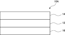
- 1 is a diagram showing an example of a laminate film for projected image display according to the present invention.
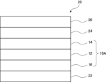
- 1 is a diagram showing an example of a laminated glass for a projection image display according to the present invention.
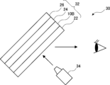
- FIG. 1 is a diagram showing an example of a projection image display system according to the present invention.
- angles e.g., angles such as “90°”
- their relationships e.g., "parallel,” “horizontal,” “vertical,” etc.
- the term "selective" in reference to circularly polarized light means that the amount of either the right-handed or left-handed circularly polarized component of light is greater than the other circularly polarized component.
- the degree of circular polarization of light is preferably 0.3 or more, more preferably 0.6 or more, and even more preferably 0.8 or more. It is particularly preferable that it is substantially 1.0.
- the degree of circular polarization is a value expressed as
- the term "sense" in relation to circularly polarized light means right-handed or left-handed circularly polarized light.
- the sense of circularly polarized light is defined as follows: when the tip of the electric field vector rotates clockwise as time increases when viewed as if the light is traveling toward you, it is right-handed circularly polarized light, and when it rotates counterclockwise, it is left-handed circularly polarized light.
- the term "sense” is sometimes used to refer to the direction of the helix of the cholesteric liquid crystal.
- the helix of the cholesteric liquid crystal When the helix of the cholesteric liquid crystal is twisted to the right (sense), it reflects right-handed circularly polarized light and transmits left-handed circularly polarized light, and when the sense is left, it reflects left-handed circularly polarized light and transmits right-handed circularly polarized light.
- the term “light” refers to visible light and natural light (non-polarized) unless otherwise specified.
- Visible light is electromagnetic light with a wavelength that can be seen by the human eye, and generally refers to light in the wavelength range of 380 to 780 nm.
- reflected light and “transmitted light” are used to include scattered light and diffracted light.
- the polarization state of each wavelength of light can be measured using a spectroradiometer or spectrometer equipped with a circular polarizer.
- the intensity of light measured through a right circular polarizer corresponds to IR
- the intensity of light measured through a left circular polarizer corresponds to IL.
- Measurements can also be made by attaching a circular polarizer to an illuminance meter or optical spectrometer. The ratio can be measured by attaching a right circular polarizer and measuring the amount of right circular polarization, and attaching a left circular polarizer and measuring the amount of left circular polarization.
- p-polarized light refers to polarized light that vibrates in a direction parallel to the plane of incidence of light.
- the plane of incidence is perpendicular to the reflecting surface (such as the surface of laminated glass) and includes the incident and reflected light rays.
- the vibration plane of the electric field vector is parallel to the plane of incidence.
- the front phase difference (in-plane retardation) is a value measured using an AxoScan manufactured by Axometrics.
- the measurement wavelength is 550 nm unless otherwise specified.
- projection image refers to an image that is not the surrounding scenery such as the front, but is based on the projection of light from the projector used.
- the projection image is observed by an observer as a virtual image that appears to appear beyond the projection image display portion of the windshield glass.
- a "screen image” refers to an image displayed on an image display device (imager) or an image rendered by an image display device onto an intermediate image screen or the like.
- An image is a real image, as opposed to a virtual image.
- the images and projected pictures may be either monochrome images, multi-color images having two or more colors, or full-color images.
- the laminate film for projection image display of the present invention is characterized in that the surface of the heat seal layer opposite to the support exhibits a predetermined roughness, and that the heat seal layer has a predetermined thickness.
- the average value A of the arithmetic mean height Sa described later is the average value of the arithmetic mean height Sa measured in a wide observation field, and represents the degree of the height of the large periodic uneven structure on the surface of the heat seal layer.
- the laminated film for projection display 100 shown in Figure 1 includes a support 102, a selective reflection layer 104 arranged on one surface of the support 102, and a heat seal layer 106 arranged on the other surface of the support 102.
- the surface 106A of the heat seal layer 106 opposite to the support 102 side has a large average value A and has a large periodic uneven structure as shown in the figure.
- Figure 2 is a diagram of such a laminated film for projection display 100 attached to a glass substrate 108. As shown in Fig. 2, when the surface 106A of the heat seal layer 106 shown in Fig.
- the uneven structure on the surface 106A is transferred to the opposite surface (the surface of the heat seal layer 106 on the support 102 side), and as a result, the uneven structure is also transferred to the surface of the selective reflection layer 104. If the surface of the selective reflection layer 104 has such an uneven structure, it can lead to distortion of the projected image.
- the average value A is adjusted to be equal to or less than a predetermined value so as to prevent the above problems from occurring.
- the average value B of the arithmetic mean height S described later is the average value of the arithmetic mean height Sa measured in a narrow observation field, and represents the degree of height of the small periodic uneven structure on the surface of the heat seal layer.
- the uneven structure causes small gaps to be generated between the glass substrate and the heat seal layer during bonding. Such gaps become an escape route for air contained between the glass substrate and the heat seal layer during bonding, and as a result, air bubbles are less likely to exist between the glass substrate and the heat seal layer, improving the visibility of the projected image.
- the average value B is adjusted to be a predetermined value or more so that the above-mentioned effects can be obtained.
- the heat seal layer has a predetermined thickness or more, thereby improving the impact resistance of the laminated glass for a projection image display obtained by using the laminated film for a projection image display.
- FIG. 3 is a schematic diagram showing an example of the laminate film for projection image display of the present invention.
- 3 includes a support 12, a selective reflection layer 14 disposed on one surface of the support 12, and a heat seal layer 16 disposed on the other surface of the support 12.
- the surface of the heat seal layer 16 opposite to the support 12 satisfies the requirements of average value A and average value B described below.
- the average value A and the average value B which are characteristic points of the present invention, and the thickness of the heat seal layer will be described in detail below.
- the average value A and the average value B are values obtained under measurement conditions with different ranges of the observation area, and as described above, the average value A represents the height of a large uneven structure such as a ripple on the surface of the heat seal layer, and the average value B represents the height of a finer uneven structure in a partial range of the ripple on the surface of the heat seal layer.
- the arithmetic mean height Sa of the surface of the heat seal layer of the laminated film for projected image display opposite to the support side is calculated. More specifically, the arithmetic mean height Sa is measured in a range of a visual field size (vertical 3700 ⁇ m ⁇ horizontal 4900 ⁇ m) for three different points on the surface of the heat seal layer of the laminated film for projected image display using Vertscan 2.0 (manufactured by Ryoka Systems Co., Ltd.). The conditions for the above measurement are as follows.
- the average value (arithmetic mean value) of the arithmetic mean heights Sa at the three points calculated by the above measurement is calculated, and the obtained value is defined as the average value A.
- the average value A is 40 nm or less.
- the average value A is preferably 30 nm or less, more preferably 20 nm or less, in that the visibility of an image projected on a laminated glass for a projection image display obtained by using two glass substrates and a laminated film for a projection image display is more excellent.
- the lower limit is not particularly limited, but may be 1 nm or more, and is often 5 nm or more.
- the arithmetic mean height Sa of the surface of the heat seal layer of the laminated film for projected image display opposite to the support side is calculated. More specifically, the arithmetic mean height Sa is measured in a range of a visual field size (vertical 180 ⁇ m ⁇ horizontal 240 ⁇ m) for three different points on the surface of the heat seal layer of the laminated film for projected image display using Vertscan 2.0 (manufactured by Ryoka Systems Co., Ltd.). The conditions for the above measurement are as follows.
- the average value (arithmetic mean value) of the arithmetic mean heights Sa at the three points calculated by the above measurement is calculated, and the obtained value is designated as the average value B.
- the average value B is 7 nm or more.
- the average value B is preferably 15 nm or more, more preferably 20 nm or more, in that the visibility of an image projected on a laminated glass for a projection image display obtained by using two glass substrates and a laminated film for a projection image display is more excellent.
- the upper limit is not particularly limited, but may be 40 nm or less, and is often 30 nm or less.
- the average thickness of the heat seal layer is 5 ⁇ m or more, preferably 7 ⁇ m or more, more preferably 9 ⁇ m or more, in order to provide a laminated glass for a projection image display obtained by using two glass substrates and the laminated film for a projection image display with better impact resistance.
- the upper limit is not particularly limited, but is preferably 20 ⁇ m or less, more preferably 15 ⁇ m or less, in order to reduce the thickness.
- the method for measuring the average thickness is as follows: the heat seal layer is cut with a microtome to cut out a cross section, the cross section is observed with a SEM (Scanning Electron Microscope), the thickness is measured at three different positions on the heat seal layer, and the average value (arithmetic mean value) of the measured values is calculated to obtain the average thickness.
- SEM Sccanning Electron Microscope
- the heat seal layer may have a single layer structure or a multi-layer structure having two or more layers.
- the average total thickness of the heat seal layer may be within the above range.
- the average total thickness (average thickness) of heat seal layer 1 and heat seal layer 2 may be 5 ⁇ m or more.
- the support is a member that supports the selective reflection layer and the heat seal layer.
- the front retardation Re of the support is not particularly limited, but is preferably 10 nm or less, and more preferably 5 nm or less.
- the absolute value of the retardation Rth in the thickness direction of the support is not particularly limited, but is preferably 40 nm or less, more preferably 30 nm or less.
- the constituent material of the support is not particularly limited, and examples include resins such as cellulose acylate resin and acrylic resin. Among these, cellulose acylate resin is preferred, and triacetyl cellulose resin or diacetyl cellulose resin is more preferred.
- the thickness of the support is not particularly limited, but is preferably 5.0 to 1000 ⁇ m, more preferably 10 to 250 ⁇ m, and even more preferably 15 to 90 ⁇ m.
- the selective reflection layer is a layer that selectively reflects light of a certain wavelength.
- the selective reflection layer preferably exhibits selective reflection in a part of the visible light wavelength range. It is sufficient for the selective reflection layer to reflect light for projected image display.
- the laminated film for projected image display may contain only one selective reflection layer, or may contain two or more selective reflection layers.
- the central wavelength ⁇ of selective reflection of the selective reflection layer means the wavelength at the center of gravity of the reflection peak of the reflection spectrum measured from the normal direction of the selective reflection layer.
- the central wavelengths of selective reflection of the two or more selective reflection layers may be the same or different, but are preferably different.
- the central wavelengths of selective reflection of the two layers preferably differ by 60 nm or more, more preferably by 80 nm or more, and even more preferably by 100 nm or more.
- a selective reflection layer having a central wavelength of selective reflection of 500 to 650 nm preferably 500 to 600 nm
- a selective reflection layer having a central wavelength of selective reflection of 650 to 900 nm preferably 650 to 780 nm
- the selective reflection layer is preferably a polarizing reflection layer that selectively reflects linearly polarized light, circularly polarized light, or elliptically polarized light.
- the polarized light reflective layer is preferably a circularly polarized light reflective layer or a linearly polarized light reflective layer.
- the circularly polarized light reflective layer is a layer that reflects circularly polarized light of one sense and transmits circularly polarized light of the other sense at the central wavelength of selective reflection.
- the linearly polarized light reflective layer is a layer that reflects linearly polarized light in one polarization direction at the central wavelength of selective reflection and transmits linearly polarized light in a polarization direction perpendicular to the polarization direction.
- the polarized light reflective layer can transmit polarized light that is not reflected, and can transmit a portion of light even in the wavelength range in which the selective reflection layer shows reflection.
- the selective reflection layer which is a circularly polarized light reflective layer, is preferably a cholesteric liquid crystal layer.
- the cholesteric liquid crystal layer is a layer in which a cholesteric liquid crystal phase is fixed.
- the cholesteric liquid crystal layer may be a layer in which the orientation of the liquid crystal compound in the cholesteric liquid crystal phase is maintained.
- the cholesteric liquid crystal layer may be a layer in which the polymerizable liquid crystal compound is oriented in the cholesteric liquid crystal phase, polymerized and cured by ultraviolet irradiation or heating to form a layer with no fluidity, and at the same time, changed to a state in which the orientation form is not changed by an external field or external force.
- the optical properties of the cholesteric liquid crystal phase are maintained in the layer, and the liquid crystal compound in the layer does not need to exhibit liquid crystallinity any more.
- the polymerizable liquid crystal compound may be polymerized by a curing reaction and lose its liquid crystallinity.
- a cholesteric liquid crystal layer exhibits circularly polarized light selective reflection, selectively reflecting circularly polarized light of one sense, either right-handed or left-handed, and transmitting circularly polarized light of the other sense.
- Many layers formed from compositions containing polymerizable liquid crystal compounds have been known as layers in which a cholesteric liquid crystal phase exhibiting circularly polarized light selective reflectivity is fixed, and these conventional techniques can be referred to for the cholesteric liquid crystal layer.
- the selective reflection central wavelength and half width of the cholesteric liquid crystal layer can be determined as follows.
- a peak of reduced transmittance is observed in the selective reflection band. If the value of the wavelength on the short wavelength side of the two wavelengths that have an intermediate (average) transmittance between the minimum transmittance of this peak and the transmittance before the decrease is ⁇ l (nm) and the value of the wavelength on the long wavelength side is ⁇ h (nm), the central wavelength ⁇ and half width ⁇ of the selective reflection can be expressed by the following formula.
- the central wavelength of the selective reflection obtained as described above substantially coincides with the wavelength at the center of gravity of the reflection peak of the circularly polarized light reflection spectrum measured from the normal direction of the cholesteric liquid crystal layer.
- the pitch of the cholesteric liquid crystal phase depends on the type of chiral agent used together with the polymerizable liquid crystal compound, or on its concentration, so the desired pitch can be obtained by adjusting these.
- the methods described in "Introduction to Liquid Crystal Chemistry Experiments” edited by the Japanese Liquid Crystal Society, published by Sigma Publishing in 2007, p. 46, and "Liquid Crystal Handbook” edited by the Liquid Crystal Handbook Editorial Committee, Maruzen, p. 196 can be used.
- the laminated film for projected images contains two or more cholesteric liquid crystal layers
- the cholesteric liquid crystal layers in the laminated glass for projected images are arranged in order of the shortest central wavelength of selective reflection when viewed from the viewing side (the vehicle interior side).
- Cholesteric liquid crystal layers having either a right or left helical sense are used for each cholesteric liquid crystal layer.
- the sense of the reflected circularly polarized light of the cholesteric liquid crystal layer matches the sense of the helix.
- the helical senses of the cholesteric liquid crystal layers with different central wavelengths of selective reflection may all be the same or may include some that are different, but it is preferable that they are the same.
- the laminate film for projected image display does not include a cholesteric liquid crystal layer with a different helical sense as a cholesteric liquid crystal layer that shows selective reflection in the same or overlapping wavelength range. This is to avoid the transmittance in a specific wavelength range decreasing to, for example, less than 50%.
- ⁇ n can be adjusted by adjusting the type and mixing ratio of the polymerizable liquid crystal compound, or by controlling the temperature during alignment fixation.
- a plurality of cholesteric liquid crystal layers having the same pitch P and the same helical sense may be laminated. By laminating cholesteric liquid crystal layers having the same pitch P and the same helical sense, it is possible to increase the circular polarization selectivity at a specific wavelength.
- a separately prepared cholesteric liquid crystal layer may be stacked using an adhesive or the like, or a liquid crystal composition containing a polymerizable liquid crystal compound or the like may be applied directly to the surface of the previous cholesteric liquid crystal layer formed by the method described below, and the alignment and fixing steps may be repeated.
- the thickness of the cholesteric liquid crystal layer is preferably from 0.05 to 10 ⁇ m, more preferably from 0.1 to 8.0 ⁇ m, and even more preferably from 0.2 to 6.0 ⁇ m.
- the total thickness of the cholesteric liquid crystal layers in the laminate film for projected image display is preferably 2.0 to 30 ⁇ m, more preferably 2.5 to 25 ⁇ m, and even more preferably 3.0 to 20 ⁇ m.
- the materials and method for producing the cholesteric liquid crystal layer will be described below.
- the material used for forming the cholesteric liquid crystal layer includes a liquid crystal composition containing a polymerizable liquid crystal compound and a chiral agent (optically active compound).
- the liquid crystal composition may further contain a surfactant and a polymerization initiator, if necessary.
- the liquid crystal composition described above which is prepared by mixing these components and dissolving them in a solvent or the like, is applied to a support, an alignment layer, or a cholesteric liquid crystal layer serving as an underlying layer, and after cholesteric alignment maturation, the liquid crystal composition is cured and fixed to form a cholesteric liquid crystal layer.
- the polymerizable liquid crystal compound may be either a rod-shaped liquid crystal compound or a discotic liquid crystal compound, but is preferably a rod-shaped liquid crystal compound.
- rod-shaped polymerizable liquid crystal compounds that form a cholesteric liquid crystal layer include rod-shaped nematic liquid crystal compounds.
- Preferred rod-shaped nematic liquid crystal compounds include azomethines, azoxys, cyanobiphenyls, cyanophenyl esters, benzoates, cyclohexanecarboxylic acid phenyl esters, cyanophenylcyclohexanes, cyano-substituted phenylpyrimidines, alkoxy-substituted phenylpyrimidines, phenyldioxanes, tolanes, and alkenylcyclohexylbenzonitriles.
- a polymerizable liquid crystal compound can be obtained by introducing a polymerizable group into a liquid crystal compound.
- the polymerizable group include an unsaturated polymerizable group, an epoxy group, and an aziridinyl group, with an unsaturated polymerizable group being preferred, and an ethylenically unsaturated polymerizable group being more preferred.
- the polymerizable group can be introduced into the molecule of the liquid crystal compound by various methods.
- the number of polymerizable groups possessed by the polymerizable liquid crystal compound is preferably 1 to 6, more preferably 1 to 3.
- the polymerizable liquid crystal compound there are mentioned the compounds described in Makromol. Chem. , Vol. 190, p. 2255 (1989), Advanced Materials Vol.
- the polymerizable liquid crystal compound may be used alone or in combination of two or more kinds.
- the content of the polymerizable liquid crystal compound in the liquid crystal composition is preferably 80 to 99.9 mass %, more preferably 85 to 99.5 mass %, and even more preferably 90 to 99 mass %, based on the solid content mass (mass excluding the solvent) of the liquid crystal composition.
- the chiral agent has the function of inducing a helical structure in the cholesteric liquid crystal phase. Since the sense or pitch of the helical structure induced by the chiral compound varies depending on the compound, the chiral compound may be selected according to the purpose.
- the chiral agent is not particularly limited, and a known compound can be used. Examples of the chiral agent include compounds described in Liquid Crystal Device Handbook (Chapter 3, Section 4-3, Chiral Agents for TN and STN, p. 199, edited by the 142nd Committee of the Japan Society for the Promotion of Science, 1989), JP-A No. 2003-287623, JP-A No. 2002-302487, JP-A No. 2002-080478, JP-A No. 2002-080851, JP-A No. 2010-181852, and JP-A No. 2014-034581.
- Chiral agents generally contain an asymmetric carbon atom, but axially or planarly asymmetric compounds that do not contain an asymmetric carbon atom can also be used as chiral agents.
- Examples of axially or planarly asymmetric compounds include binaphthyl, helicene, paracyclophane, and derivatives thereof.
- the chiral agent may have a polymerizable group. When both the chiral agent and the liquid crystal compound have a polymerizable group, a polymer having a repeating unit derived from the polymerizable liquid crystal compound and a repeating unit derived from the chiral agent can be formed by a polymerization reaction between the polymerizable chiral agent and the polymerizable liquid crystal compound.
- the polymerizable group of the polymerizable chiral agent is preferably the same type of group as the polymerizable group of the polymerizable liquid crystal compound. Therefore, the polymerizable group of the chiral agent is also preferably an unsaturated polymerizable group, an epoxy group or an aziridinyl group, more preferably an unsaturated polymerizable group, and even more preferably an ethylenically unsaturated polymerizable group.
- the chiral agent may also be a liquid crystal compound.
- isosorbide derivatives As the chiral agent, isosorbide derivatives, isomannide derivatives, binaphthyl derivatives, etc. can be preferably used.
- isosorbide derivative a commercially available product such as LC-756 manufactured by BASF Corporation may be used.
- the chiral agent may be used alone or in combination of two or more kinds.
- the content of the chiral dopant in the liquid crystal composition is preferably from 0.01 to 200 mol %, more preferably from 1 to 30 mol %, based on the total molar amount of the polymerizable liquid crystal compound.
- the liquid crystal composition preferably contains a polymerization initiator.
- the polymerization initiator used is preferably a photopolymerization initiator capable of initiating the polymerization reaction by irradiation with ultraviolet light.
- the polymerization initiator may be used alone or in combination of two or more kinds.
- the content of the photopolymerization initiator in the liquid crystal composition is preferably from 0.1 to 20% by mass, and more preferably from 0.5 to 5% by mass, based on the content of the polymerizable liquid crystal compound.
- the liquid crystal composition preferably contains a solvent, and the solvent is preferably an organic solvent.
- the organic solvent is not particularly limited, and examples thereof include ketones, alkyl halides, amides, sulfoxides, heterocyclic compounds, hydrocarbons, esters, and ethers.
- the liquid crystal composition may contain a crosslinking agent to improve the film strength and durability after curing.
- a crosslinking agent those which are cured by ultraviolet light, heat, moisture, etc. can be suitably used.
- the content of the crosslinking agent in the liquid crystal composition is preferably from 3 to 20% by mass, and more preferably from 5 to 15% by mass, based on the content of the polymerizable liquid crystal compound.
- the liquid crystal composition preferably contains an alignment control agent.
- the alignment control agent include fluorine (meth)acrylate polymers described in JP-A-2007-272185, paragraphs [0018] to [0043] and the like, compounds represented by formulas (I) to (IV) described in JP-A-2012-203237, paragraphs [0031] to [0034] and the like, and compounds described in JP-A-2013-113913, and the like.
- the content of the alignment control agent in the liquid crystal composition is preferably from 0.01 to 10% by mass, and more preferably from 0.01 to 5% by mass, based on the total mass of the polymerizable liquid crystal compound.
- the liquid crystal composition may further contain additives such as surfactants, polymerization inhibitors, antioxidants, UV absorbers, light stabilizers, colorants, and metal oxide particles, as necessary.
- additives such as surfactants, polymerization inhibitors, antioxidants, UV absorbers, light stabilizers, colorants, and metal oxide particles, as necessary.
- the cholesteric liquid crystal layer can be formed by applying a liquid crystal composition, in which a polymerizable liquid crystal compound and a chiral agent, and further, if necessary, a polymerization initiator and a surfactant are dissolved in a solvent, onto a support, an alignment layer, or a previously prepared cholesteric liquid crystal layer, and drying the liquid crystal composition to obtain a coating film, which is then irradiated with active light rays to polymerize the cholesteric liquid crystal composition, thereby forming a cholesteric liquid crystal layer in which cholesteric regularity is fixed.
- a laminated film consisting of a plurality of cholesteric liquid crystal layers can be formed by repeating the above-mentioned manufacturing process for the cholesteric liquid crystal layer.
- the method for applying the liquid crystal composition is not particularly limited, and examples thereof include wire bar coating, curtain coating, extrusion coating, direct gravure coating, reverse gravure coating, die coating, spin coating, dip coating, spray coating, and slide coating. Alternatively, it can be carried out by transferring a liquid crystal composition that has been separately coated on a support.
- the applied liquid crystal composition is heated to align the polymerizable liquid crystal compound.
- the heating temperature is preferably equal to or lower than 200° C., and more preferably equal to or lower than 130° C.
- This alignment treatment provides an optical thin film in which the polymerizable liquid crystal compound is twisted and aligned so as to have a helical axis in a direction substantially perpendicular to the film surface.
- the aligned liquid crystal compound can be further polymerized to harden the liquid crystal composition.
- the polymerization may be either thermal polymerization or photopolymerization utilizing light irradiation, with photopolymerization being preferred.
- the light irradiation is preferably performed using ultraviolet light, and the irradiation energy is preferably from 20 mJ/cm 2 to 50 J/cm 2 , and more preferably from 100 to 1,500 mJ/cm 2 .
- the light irradiation may be carried out under heating conditions or in a nitrogen atmosphere.
- the wavelength of the ultraviolet light to be irradiated is preferably 350 to 430 nm.
- linearly Polarized Light Reflective Layer As the selective reflection layer, a linearly polarized light reflection layer may be used.
- An example of the linearly polarized light reflective layer is a polarizer in which thin films having different refractive index anisotropy are laminated.
- a polarizer in which thin films with different refractive index anisotropy are laminated for example, those described in JP-A-9-506837 can be used.
- a commercially available product can be used as the polarizer in which thin films having different refractive index anisotropy are laminated.
- the commercially available product may be a laminate of a reflective polarizing plate and a temporary support. Examples of commercially available products include commercially available optical films sold under the trade names DBEF (registered trademark) (manufactured by 3M) and APF (Advanced Polarizing Film (manufactured by 3M)).
- the heat seal layer has the function of ensuring adhesion to the glass substrate.
- the heat seal layer is a layer for physically bonding the laminated film for projection image display and the glass substrate.
- the heat seal layer preferably contains a thermoplastic resin.
- the thermoplastic resin is preferably one having good affinity and adhesion to the glass substrate, and is preferably a resin selected from the group consisting of polyvinyl acetal resins, such as polyvinyl butyral (PVB) resin, ethylene-vinyl acetate copolymers, and chlorine-containing resins, with polyvinyl acetal resins being more preferable.
- polyvinyl butyral or an ethylene-vinyl acetate copolymer is preferred, and polyvinyl butyral is more preferred.
- Polyvinyl butyral can be obtained by acetalizing polyvinyl alcohol with butyraldehyde.
- the degree of acetalization of polyvinyl butyral is not particularly limited, but is preferably 40% or more, more preferably 60% or more.
- the upper limit is not particularly limited, but is preferably 85% or less, more preferably 75% or less.
- Polyvinyl alcohol used in the synthesis of polyvinyl butyral is usually obtained by saponifying polyvinyl acetate, and polyvinyl alcohol having a saponification degree of 80 to 99.8 mol % is generally used.
- the degree of polymerization of the polyvinyl alcohol is preferably 200 to 3,000.
- the thermoplastic resin is preferably the main component of the heat seal layer, where the main component means a component that accounts for 50% by mass or more of the total mass of the heat seal layer. More specifically, the content of the thermoplastic resin in the heat seal layer is preferably from 60 to 99% by mass, and more preferably from 70 to 97% by mass, based on the total mass of the heat seal layer.
- the heat seal layer may contain inorganic particles.
- the inorganic particles contained in the heat seal layer are preferably inorganic oxide particles, more preferably silica (silicon dioxide) particles, aluminum oxide particles, titanium dioxide particles or zirconium oxide particles, and further preferably silica particles.
- the inorganic particles are preferably made up of primary particles, with secondary particles being formed by agglomeration of the primary particles.
- the average primary particle size of the inorganic particles is not particularly limited, but is preferably 5 to 50 nm, and more preferably 5 to 15 nm.
- the average secondary particle size of the inorganic particles is not particularly limited, but is preferably 100 to 500 nm.
- the content of the inorganic particles in the heat seal layer is not particularly limited, but is preferably 1% by mass or more, more preferably 9% by mass or more, based on the total mass of the heat seal layer.
- the upper limit is not particularly limited, but is preferably 40% by mass or less, more preferably 30% by mass or less.
- the content of the inorganic particles in the heat seal layer may affect the above-mentioned average value B, it is preferable to adjust it within the above range.
- the average primary particle size of inorganic particles is measured by observation with a transmission electron microscope. Specifically, the diameters of circles circumscribing the primary particles are determined for 50 randomly selected primary particles, and the arithmetic average is taken as the average primary particle size.
- the magnification of the transmission electron microscope is set to any magnification between 500,000 and 5,000,000 that allows the primary particle size to be determined.
- the average secondary particle diameter is a value measured by performing spherical fitting (refractive index 1.46) using a laser diffraction scattering type particle size distribution measuring device.
- the measuring device for example, MicroTrac MT3000 manufactured by Microtrac Bell can be used.
- the heat seal layer may contain a leveling agent.
- a leveling agent a known leveling agent can be used, for example, a surfactant can be mentioned, and among them, a fluorine-based surfactant or a silicone-based surfactant is preferable.
- the fluorine content in the fluorosurfactant is preferably 3 to 40 mass%, more preferably 5 to 30 mass%, and even more preferably 7 to 25 mass%.
- a fluorosurfactant having a fluorine content within this range is effective in terms of the uniformity of the thickness of the coating film and liquid saving properties.
- the amount of the leveling agent contained in the heat seal layer is not particularly limited, but is preferably 0.005 to 0.5% by mass, and more preferably 0.01 to 0.1% by mass, based on the total mass of the heat seal layer.
- the heat seal layer exhibits the predetermined average values A and B on the surface opposite to the support.
- the water contact angle of the surface of the heat seal layer opposite to the support is not particularly limited, but is preferably 90° or less, more preferably 80° or less, and even more preferably 70° or less, in order to provide a laminated glass for a projection image display obtained by using two glass substrates and a laminated film for a projection image display with better impact resistance.
- the lower limit is not particularly limited, but is often 10° or more, and more often 30° or more.
- the water contact angle was measured as follows.
- a contact angle meter CA-X (manufactured by Kyowa Interface Science Co., Ltd.) is used to make a droplet of 1.0 mm diameter using pure water at a needle tip in an environment of 20°C and 65% RH, and this is brought into contact with the surface of the heat seal layer to make a droplet. 25 seconds after the heat seal layer surface comes into contact with the pure water, the angle between the tangent to the pure water surface and the heat seal layer surface at the point where the heat seal layer surface comes into contact with the pure water is measured, and the average value of these is taken as the water contact angle of the laminate film for projection image display.
- the method for forming the heat seal layer is not particularly limited as long as it can form a heat seal layer having the above-mentioned average values A and B and an average thickness within the predetermined ranges.
- a method using a composition for forming a heat seal layer containing a thermoplastic resin and inorganic particles is preferred. More specifically, a method of forming a heat seal layer by applying the composition for forming a heat seal layer onto a support is preferred.
- the contents of the thermoplastic resin and the inorganic particles in the composition for forming a heat seal layer are preferably adjusted to the above-mentioned contents of the thermoplastic resin and the inorganic particles in the heat seal layer.
- the composition for forming a heat seal layer may contain the above-mentioned leveling agent.
- the content of the leveling agent in the composition for forming a heat seal layer is preferably adjusted to the above-mentioned content of the leveling agent in the heat seal layer.
- the composition for forming a heat seal layer preferably contains a solvent.
- the type of the solvent is not particularly limited, and examples thereof include water and organic solvents, with organic solvents being preferred.
- examples of the organic solvent include ketones, alkyl halides, amides, sulfoxides, heterocyclic compounds, hydrocarbons, esters, and ethers.
- the solid content concentration in the composition for forming a heat seal layer is preferably 3% by mass or more, more preferably 5% by mass or more, based on the total mass of the composition for forming a heat seal layer, in order to lower the average value A.
- the upper limit is not particularly limited, but is preferably 30% by mass or less, more preferably 20% by mass or less.
- the solid content concentration in the composition for forming a heat seal layer is preferably 16 mass% or more relative to the total mass of the composition for forming a heat seal layer, in order to make the average value A lower.
- the solid content means the components forming the heat seal layer, excluding the solvent. Even if the components are in a liquid form, they are counted as solids.
- the method of applying the composition for forming the heat seal layer is not particularly limited, and examples include wire bar coating, curtain coating, extrusion coating, direct gravure coating, reverse gravure coating, die coating, spin coating, dip coating, spray coating, and slide coating.
- the coating film obtained by coating may be subjected to a drying treatment, if necessary.
- the drying treatment may be a heat treatment.
- the heating temperature in the heat treatment is not particularly limited, but is preferably 50 to 150° C., and more preferably 60 to 140° C.
- the heating time is not particularly limited, but is preferably 0.5 to 20 minutes, and more preferably 0.5 to 10 minutes.
- the surface of the formed heat seal layer (the surface opposite to the support) may be subjected to a surface treatment, if necessary.
- a surface treatment such as a plasma treatment, an ultraviolet irradiation treatment, a corona treatment, or an electron beam irradiation treatment, with the corona treatment being preferred.
- the conditions for the hydrophilization treatment are appropriately selected depending on the type of treatment to be carried out, and are preferably adjusted so that the water contact angle of the surface of the heat seal layer falls within the above-mentioned range.
- the surface of the heat seal layer may be subjected to a roughening treatment.
- a roughening treatment By performing the roughening treatment, the ranges of the above-mentioned average value A and average value B (particularly, average value B) can be adjusted.
- surface roughening treatments include sanding and blasting.
- Sanding is a treatment in which a substrate such as a disk or belt that holds abrasive grains is used to form an uneven shape on the surface of the object to be polished.
- Blasting is a treatment in which abrasive grains are sprayed onto the surface of the object to be polished to form an uneven shape.
- the laminated film for projected image display may contain other members in addition to the above-mentioned members (support, selective reflection layer, and heat seal layer).
- the laminate film for projection image display may include an alignment layer, which can function as a lower layer of the above-mentioned cholesteric liquid crystal layer and a lower layer of the retardation layer described below.
- the alignment layer can be provided by a method such as rubbing an organic compound such as a polymer, oblique deposition of an inorganic compound, formation of a layer having microgrooves, and deposition of an organic compound using the Langmuir-Blodgett technique (LB film).
- LB film Langmuir-Blodgett technique
- an alignment layer that exhibits an alignment function when an electric field, a magnetic field, or light is applied may be used.
- a rubbing treatment on the alignment layer made of a polymer, and then apply the liquid crystal composition to the rubbed surface.
- the rubbing treatment can be carried out by rubbing the surface of the polymer layer with paper or cloth in a certain direction.
- the polymer include polyimide, polyvinyl alcohol, polyester, polyarylate, polyamideimide, polyetherimide, polyamide, and modified polyamide.
- the thickness of the alignment layer is preferably from 0.01 to 5.0 ⁇ m, and more preferably from 0.05 to 2.0 ⁇ m.
- the laminated film for projection image display may include a retardation layer.
- the retardation layer changes the state of incident polarized light by imparting a phase difference (optical path difference) to two orthogonal polarized light components.
- the retardation layer is preferably provided so as to be on the viewing side with respect to all the selective reflection layers (cholesteric liquid crystal layers) during use.
- the retardation layer is preferably disposed between the support and the selective reflection layer.
- retardation layers include stretched polycarbonate films, stretched norbornene polymer films, oriented transparent films containing inorganic particles with birefringence such as strontium carbonate, thin films formed by obliquely depositing inorganic dielectrics onto a support, and films in which liquid crystal compounds are uniaxially aligned and fixed in orientation.
- the retardation layer a film in which a polymerizable liquid crystal compound is uniaxially aligned and fixed in alignment is preferred.
- the retardation layer can be formed by applying a liquid crystal composition containing a polymerizable liquid crystal compound to a temporary support or the surface of an alignment layer, forming the polymerizable liquid crystal compound in the coating film into a nematic alignment in the liquid crystal state, and then fixing the alignment by curing.
- the retardation layer can be formed in the same manner as the formation of the cholesteric liquid crystal layer described above, except that no chiral agent is added to the liquid crystal composition.
- the heating temperature is preferably 50 to 120°C, more preferably 60 to 100°C.
- the retardation layer is a layer that converts linearly polarized light into circularly polarized light
- the retardation layer is preferably configured to give a front retardation of ⁇ /4, and may be configured to give a front retardation of 3 ⁇ /4.
- the angle of the slow axis may be arranged so as to be in a direction that converts the incident linearly polarized light into circularly polarized light.
- the retardation layer preferably has a front retardation at a wavelength of 550 nm in the range of 100 to 450 nm, more preferably in the range of 120 to 200 nm or 300 to 400 nm.
- the thickness of the retardation layer is not particularly limited, but is preferably from 0.2 to 300 ⁇ m, and more preferably from 0.4 to 150 ⁇ m.
- the thickness of the retardation layer formed from the liquid crystal composition is not particularly limited, but is preferably 0.2 to 10 ⁇ m, and more preferably 0.4 to 5.0 ⁇ m.
- the laminate film for projected image display may include a polarization conversion layer.
- the polarization conversion layer is preferably disposed on the side opposite to the support side of the selective reflection layer.
- polarization conversion layer is a layer in which a helical alignment structure of a liquid crystal compound is fixed.
- a polarization conversion layer that satisfies the following relationship formulas (i) and (ii) is preferred, where x is the pitch number of the helical structure of the polarization conversion layer and y (unit: ⁇ m) is the film thickness of the polarization conversion layer.
- the pitch of the helical structure (i) 0.3 ⁇ x ⁇ 2.0 (ii) 0.5 ⁇ y ⁇ 7.0
- the pitch of the helical structure is the length of the helical axis direction in which the director of the liquid crystal compound constituting the helical alignment structure rotates 360 degrees, as in the case of a cholesteric liquid crystal layer.
- one pitch in which the director of the liquid crystal compound rotates 360 degrees is considered to be one pitch.
- the polarization conversion layer in which the helical orientation structure of the liquid crystal compound is fixed preferably has a pitch number of 0.3 to 2.0 and a film thickness of 0.5 to 7.0 ⁇ m.
- the laminated film for projection image display may include an adhesive layer, which is used to ensure adhesion between layers.
- the position of the adhesive layer is not particularly limited, but examples thereof include between cholesteric liquid crystal layers, between the selective reflection layer and the retardation layer, and between the selective reflection layer and the polarization conversion layer.
- the adhesive layer may be formed from any suitable adhesive. Adhesives include hot melt types, heat curing types, light curing types, reaction curing types, and pressure sensitive adhesive types that do not require curing.
- the thickness of the adhesive layer is preferably from 0.5 to 10 ⁇ m, and more preferably from 1.0 to 5.0 ⁇ m.
- the thickness of the adhesive layer formed using the OCA tape is preferably 10 to 50 ⁇ m, and more preferably 15 to 30 ⁇ m.
- the above-mentioned laminated film for projected image display can be suitably used as laminated glass for projected image display by sandwiching it between two glass substrates.
- the laminated glass for projected image display can be suitably applied to window glass and windshield glass of general vehicles such as cars and trains, airplanes, ships, motorcycles, and playground equipment.
- the laminated glass for projected image display is preferably used as a windshield or windshield glass located at the front in the traveling direction of the vehicle.
- FIG. 4 is a schematic diagram showing an example of the laminated glass for a projection image display according to the present invention.
- 4 includes a first glass substrate 22, a laminated film 10A for a projection image display, an intermediate film 24, and a second glass substrate 26.
- the heat seal layer in the laminated film 10A for a projection image display is disposed on the first glass substrate 22 side.
- the components constituting the laminated glass for projected image display will be described in detail below.
- the laminated film for projected images is as described above, and a description thereof will be omitted.
- the first glass substrate and the second glass substrate may be a glass substrate generally used for laminated glass.
- a glass substrate having a visible light transmittance of 80% or less, such as 73% or 76%, such as a green glass having high heat insulating properties may be used.
- the thickness of the first glass substrate and the second glass substrate is not particularly limited, but is preferably 0.5 to 5.0 mm, and more preferably 1.0 to 3.0 mm.
- the first and second glass substrates may be made of the same material or have different thicknesses.
- the interlayer film may be any known interlayer film used in laminated glass for vehicles, for example, a resin film containing a resin selected from the group consisting of polyvinyl butyral (PVB), ethylene-vinyl acetate copolymer, and chlorine-containing resin.
- the above resin is preferably the main component of the interlayer film, where the main component means a component that accounts for 50% by mass or more of the interlayer film.
- polyvinyl butyral or ethylene-vinyl acetate copolymer is preferred, and polyvinyl butyral is more preferred.
- Polyvinyl butyral can be obtained by acetalizing polyvinyl alcohol with butyraldehyde.
- the degree of acetalization of polyvinyl butyral is not particularly limited, but is preferably 40% or more, more preferably 60% or more.
- the upper limit is not particularly limited, but is preferably 85% or less, more preferably 75% or less.
- Polyvinyl alcohol used in the synthesis of polyvinyl butyral is usually obtained by saponifying polyvinyl acetate, and polyvinyl alcohol having a saponification degree of 80 to 99.8 mol % is generally used.
- the degree of polymerization of the polyvinyl alcohol is preferably 200 to 3,000.
- the method for producing the laminated glass for a projection image display of the present invention is not particularly limited, and any known method can be used.
- the laminated glass can be produced by sandwiching an interlayer film for laminated glass between two glass substrates, repeatedly subjecting the interlayer film to heat treatment and pressure treatment (e.g., treatment using a rubber roller) several times, and finally subjecting the interlayer film to heat treatment under pressure using an autoclave or the like.
- One example of a method for producing laminated glass for a projection image display including a laminate film for a projection image display and an interlayer film is a method in which a heat seal layer of the laminate film for a projection image display is bonded to a first glass substrate, the resulting laminate is laminated to a second glass substrate via the interlayer film, and a heat treatment and/or pressure treatment is carried out.
- the projection image display system of the present invention is a system including the above-mentioned laminated glass for projection image display and a projector.
- FIG. 5 shows an example of a projection image display system.
- the projection image display system 30 includes a laminated glass 32 for projecting images and a projector 34.
- the projection image display system 30 is used in a vehicle such as a passenger car, for example.
- the laminated glass 32 for a projection image display includes a first glass substrate 22 , a laminated film 10 B for a projection image display, an intermediate film 24 , and a second glass substrate 26 .
- the laminated film 10B for projection image display has a heat seal layer, a support, a retardation layer, and a selective reflection layer in this order.
- the laminated film 10B for projection image display is attached to the first glass substrate 22 via the heat seal layer.
- a projector 34 emits p-polarized projection light
- a laminated glass 32 for projection image display reflects the p-polarized light to display an image.
- the retardation layer first converts the incident p-polarized projection light into circularly polarized light.
- the selective reflection layer selectively reflects this circularly polarized light, causing it to re-enter the retardation layer.
- the retardation layer further converts the circularly polarized light into p-polarized light.
- the laminated film 10B for projected images reflects the incident p-polarized projection light while keeping it as p-polarized light.
- the retardation layer is set to convert the incident p-polarized light into the circularly polarized light of the rotation direction reflected by the selective reflection layer according to the sense of the circularly polarized light selectively reflected by the selective reflection layer. That is, when the selective reflection layer selectively reflects right-handed circularly polarized light, the retardation layer is set to convert the incident p-polarized light into right-handed circularly polarized light. Conversely, when the selective reflection layer selectively reflects left-handed circularly polarized light, the retardation layer is set to convert the incident p-polarized light into left-handed circularly polarized light.
- the projector 34 preferably irradiates p-polarized projection light onto the laminated glass for projection image display 32.
- the projector 34 irradiates the windshield with p-polarized projection light at the Brewster angle, thereby eliminating reflection of the projection light on the first glass substrate 22 and the second glass substrate 26, allowing for a clearer image to be displayed.
- a “projector” is a “device that projects light or an image” and includes a “device that projects a drawn image” and emits projection light that carries the image to be displayed.
- the projector emits p-polarized projection light.
- the projector needs only to be disposed so that p-polarized projection light carrying an image to be displayed can be incident on the laminated glass for projected image display at an oblique incidence angle.
- the projector preferably includes a drawing device and reflects and displays an image (real image) drawn on a small intermediate image screen as a virtual image via a combiner. Moreover, it is preferable that the projector is one in which the imaging distance of the virtual image, that is, the imaging position of the virtual image, is variable.
- Methods for changing the imaging distance of a virtual image in a projector include, for example, moving the image generation surface (screen) (see JP 2017-021302 A), switching between multiple optical paths with different optical path lengths (see WO 2015/190157 A), changing the optical path length by inserting and/or moving a mirror, changing the focal length by using a lens assembly as an imaging lens, moving the projector, switching between multiple projectors with different virtual image imaging distances, and using a variable focus lens (see WO 2010/116912 A).
- the projector may be one that can continuously change the imaging distance of the virtual image, or one that can switch the imaging distance of the virtual image at multiple points (two or more than two points).
- the drawing device may be a device that itself displays an image, or it may be a light-emitting device that can draw an image.
- a drawing method such as a light modulator, a laser brightness modulation means, or a light deflection means for drawing.
- the drawing device means a device that includes a light source and further includes a light modulator, a laser brightness modulation means, or a light deflection means for drawing, etc., depending on the drawing method.
- LEDs light-emitting diodes
- OLEDs organic light-emitting diodes
- discharge tubes laser light sources
- laser light sources can be used.
- LEDs and discharge tubes are preferred because they are suitable as light sources for drawing devices that emit linearly polarized light, and LEDs are more preferred.
- the drawing method can be selected according to the light source to be used, and is not particularly limited.
- Examples of the drawing method include a fluorescent display tube, an LCD (Liquid Crystal Display) method using liquid crystal, an LCOS (Liquid Crystal on Silicon) method, a DLP (Digital Light Processing) method, and a scanning method using a laser.
- the drawing method may be a method using a fluorescent display tube integrated with a light source.
- the LCD method is preferable as the drawing method.
- the light emitted from the imaging device may be linearly polarized or natural (unpolarized) light.
- the emitted light is essentially linearly polarized.
- the polarization direction (transmission axis direction) of the light of the multiple wavelengths is the same.
- some commercially available drawing devices have non-uniform polarization directions in the wavelength ranges of red, green, and blue light of the emitted light (see JP 2000-221449 A). Specifically, there is known an example in which the polarization direction of green light is perpendicular to the polarization direction of red light and the polarization direction of blue light.
- the drawing device may use an intermediate image screen.
- An "intermediate image screen” is a screen on which an image is drawn. That is, in cases where the light emitted by the drawing device is not yet visible as an image, the drawing device uses this light to form a visible image on the intermediate image screen.
- the image drawn on the intermediate image screen may be projected onto the combiner by light passing through the intermediate image screen, or may be projected onto the combiner by reflecting off the intermediate image screen.
- Laminated glass for projected image displays is particularly suitable for use in combination with projectors that use lasers, LEDs, and OLEDs (organic light-emitting diodes) as light sources whose emission wavelengths are not continuous in the visible light range.
- lasers LEDs
- OLEDs organic light-emitting diodes
- the incident light is preferably incident at an oblique incidence angle of 45 to 70° with respect to the normal to the laminated film for projected image display in the laminated glass for projected image display.
- the Brewster angle of the interface between glass with a refractive index of about 1.51 and air with a refractive index of 1 is about 56°, and by making p-polarized light incident within the above-mentioned angle range, there is little reflected light from the surface of the laminated glass for projected image display on the viewing side with respect to the selective reflection layer of the incident light for projected image display, making it possible to display an image with little double image effect.
- the angle is 50 to 65°. In this case, it is sufficient that the projected image can be observed on the side where the projection light is incident, at an angle of 45 to 70°, preferably 50 to 65°, with respect to the normal to the selective reflection layer on the opposite side to the incident light.
- the incident light may be incident from any direction, such as above, below, left or right, on the laminated glass for projected image display, and may be determined according to the viewing direction. For example, it is preferable that the incident light is incident from below at an oblique incident angle as described above during use.
- the laminated film for projected image display of the laminated glass for projected image display is preferably disposed so as to reflect incident p-polarized light.
- the present invention is basically configured as described above.
- the laminated glass for projected image display, the laminated glass for projected image display, and the projected image display system of the present invention have been described in detail above, but the present invention is not limited to the above-described embodiments, and various improvements and modifications may of course be made without departing from the spirit of the present invention.
- ⁇ Preparation of cholesteric liquid crystal layer forming composition, retardation layer forming composition, and polarization conversion layer forming composition The components were mixed according to the ratios shown in Table 1 below, and the resulting mixture was filtered through a polypropylene filter having a pore size of 10 ⁇ m to prepare compositions BG1, R1, and IR1 for forming a cholesteric liquid crystal layer, composition A1 for forming a retardation layer, and composition TW-1 for forming a polarization conversion layer.
- a cellulose acylate film having a thickness of 40 ⁇ m was produced by the same production method as in Example 20 of International Publication No. 2014/112575.
- UV-531 manufactured by Teisei Kako Co., Ltd. was added to this cellulose acylate film as an ultraviolet absorbent. The amount added was 3 phr (per hundred resin).
- the prepared cellulose acylate film was passed through a dielectric heating roll at 60°C to raise the surface temperature of the film to 40°C, and then an alkaline solution having the composition shown below was applied to one side of the film at a coating amount of 14 mL/ m2 using a bar coater, and the film was allowed to remain under a steam type far-infrared heater (manufactured by Noritake Co., Limited) heated to 110°C for 10 seconds. Next, 3 mL/m 2 of pure water was applied using the same bar coater. Next, after repeating washing with a fountain coater and draining with an air knife three times, the film was allowed to stay in a drying zone at 70° C. for 5 seconds and dried to prepare a saponified cellulose acylate film 1.
- a coating solution for forming an alignment layer having the composition shown below was applied at 24 mL/ m2 using a wire bar coater, and then dried for 120 seconds with hot air at 100°C to obtain an alignment layer having a thickness of 0.5 ⁇ m.
- the alignment layer prepared above was subjected to a rubbing treatment (rayon cloth, pressure: 0.1 kgf (0.98 N), rotation speed: 1000 rpm (revolutions per minute), conveying speed: 10 m/min, number of reciprocations: 1) in a direction rotated 45° clockwise with respect to the long side direction of the support.
- Composition A1 for forming a retardation layer was applied to the surface of the alignment layer rubbed as described above using a wire bar and dried, and then the film was placed on a hot plate at 50°C and irradiated with ultraviolet light for 6 seconds using an electrodeless lamp "D bulb" (60 mW/ cm2 ) manufactured by Fusion UV Systems in an environment with an oxygen concentration of 1000 ppm or less, thereby forming a retardation layer.
- the front retardation of the produced retardation layer at a wavelength of 550 nm was measured using an AxoScan manufactured by Axometrics, and was found to be 126 nm.
- the cholesteric liquid crystal layer forming composition IR1 was further applied to the surface of the retardation layer prepared above using a wire bar at room temperature so that the thickness of the dried film after drying would be 0.4 ⁇ m, and the applied layer was dried at room temperature for 30 seconds, and then heated for 2 minutes in an atmosphere at 85° C. Thereafter, in an environment with an oxygen concentration of 1000 ppm or less, at 60° C., ultraviolet light was irradiated at an output of 60% for 6 to 12 seconds using a D bulb (90 mW/cm 2 lamp) manufactured by Fusion Co., Ltd. to fix the cholesteric liquid crystal phase, and a cholesteric liquid crystal layer IR1 having a thickness of 0.4 ⁇ m was obtained.
- a D bulb 90 mW/cm 2 lamp
- the polarization conversion layer forming composition TW1 was applied to the cholesteric liquid crystal layer R1 prepared above using a wire bar at room temperature so that the thickness of the dried film after drying would be 0.8 ⁇ m, and the applied layer was then dried at room temperature for 30 seconds and heated for 2 minutes in an atmosphere at 85° C. After that, in an environment with an oxygen concentration of 1000 ppm or less, at 60° C., ultraviolet light was irradiated at an output of 60% for 6 to 12 seconds using a D bulb (90 mW/cm 2 lamp) manufactured by Fusion Co., Ltd., to fix the polarization conversion layer and obtain a reflective film.
- a D bulb 90 mW/cm 2 lamp
- AEROSIL RX300 (manufactured by Nippon Aerosil Co., Ltd., average primary particle size 7 nm) was added to butyl acetate so that the solid content concentration was 5% by mass, and the mixture was stirred with a magnetic stirrer for 30 minutes. Then, the mixture was ultrasonically dispersed with an ultrasonic disperser (manufactured by SMT Co., Ltd., Ultrasonic Homogenizer UH-600S) for 10 minutes to prepare a silica particle dispersion.
- an ultrasonic disperser manufactured by SMT Co., Ltd., Ultrasonic Homogenizer UH-600S
- a portion of the obtained silica particle dispersion was sampled for measuring the average secondary particle diameter, and the average secondary particle diameter of the silica particles in the silica particle dispersion was measured using a Microtrac MT3000 (manufactured by Microtrac Corporation), and was found to be 190 nm.
- the above-mentioned heat seal layer-forming composition was prepared using the silica particle dispersion obtained above.
- the content of silica particles in Table 2 indicates the content of the silica particles themselves.
- Example 1 The heat seal layer forming composition HS-1 was applied to the surface of the support of the reflective film on the side on which the retardation layer was not applied using a wire bar so that the film thickness after drying would be 1 ⁇ m, and then the composition was dried at 100° C. for 1 minute to form a heat seal layer 1. Next, the heat seal layer forming composition HS-2 was further applied to the surface of the obtained heat seal layer 1 using a wire bar so that the film thickness after drying would be 5 ⁇ m, and then dried at 100° C. for 2 minutes to form a heat seal layer 2.
- the surface of the heat seal layer 2 of the laminated film prepared above was subjected to a blast treatment (time: 3 seconds) to obtain a laminated film 1 for projection image display having a retardation layer, three cholesteric liquid crystal layers (selective reflection layers), and a polarization conversion layer on one surface of the support, and a heat seal layer having a thickness of 6.0 ⁇ m on the other surface.
- Examples 2 and 3> Except for changing the composition for forming the heat seal layer when forming the heat seal layer 2 as shown in Table 3, the same procedure as in Example 1 was used to obtain laminate films 2 and 3 for projection image displays.
- Example 4 of the projection image display laminate film was obtained in the same manner as in Example 3, except that the blast treatment time was changed to 10 seconds.
- Example 5 of the projection image display laminate film was obtained in the same manner as in Example 3, except that the blast treatment time was changed to 15 seconds.
- Example 6 A laminated film 6 for projection image display was obtained in the same manner as in Example 5, except that the surface of the heat seal layer 2 after the blast treatment was further subjected to a corona treatment at a treatment amount of 88 W ⁇ min/m 2 .
- Example 7 A laminated film 7 for projection image display was obtained in the same manner as in Example 6, except that the heat seal layer 2 was coated so that the thickness after drying would be 9 ⁇ m.
- Example 8 The heat seal layer forming composition HS-1 was applied to the surface of the support of the reflective film prepared above on the side on which the retardation layer was not applied, using a wire bar so that the film thickness after drying would be 1 ⁇ m, and then dried at 100° C. for 1 minute to form a heat seal layer 1. Next, the heat seal layer forming composition HS-5 was further applied to the surface of the obtained heat seal layer 1 using a wire bar so that the film thickness after drying would be 9 ⁇ m, and then dried at 120° C. for 2 minutes to form a heat seal layer 2.
- a laminate film 8 for projection image display which has a retardation layer, three cholesteric liquid crystal layers (selective reflection layers), and a polarization conversion layer on one surface of the support, and a heat seal layer having a thickness of 10.0 ⁇ m on the other surface of the support.
- Example 9 and 10> Except for changing the composition for forming the heat seal layer when forming the heat seal layer 2 as shown in Table 3, the same procedure as in Example 8 was used to obtain laminate films 9 and 10 for projection image display.
- Example 1 A laminate film C1 for projection image display was obtained in the same manner as in Example 8, except that the composition for forming the heat seal layer when forming the heat seal layer 2 was changed as shown in Table 3, and further, the composition was applied using a wire bar so that the film thickness after drying would be 1.5 ⁇ m.
- Comparative Examples 2 and 3 The same procedure as in Comparative Example 1 was used to obtain laminate films C2 and C3 for projection image display, except that the composition for forming the heat seal layer when forming the heat seal layer 2 was changed as shown in Table 3, and furthermore, coating was performed using a wire bar so that the film thickness after drying would be 5 ⁇ m.
- ⁇ Measurement> Average value A of arithmetic mean height Sa
- the arithmetic mean height Sa was measured at three different points on the surface of the heat seal layer of the laminated film for projection display obtained in the examples and comparative examples using Vertscan 2.0 (manufactured by Ryoka Systems Co., Ltd.) at a lens magnification of ⁇ 2.5, a lens barrel magnification of ⁇ 0.5, and Wave mode with a field of view size of 3700 ⁇ m ⁇ 4900 ⁇ m, and the average value (arithmetic mean value) was taken as the average value A.
- the arithmetic mean height Sa was measured at three different points on the surface of the heat seal layer of the laminated film for projection image display obtained in the examples and comparative examples using Vertscan 2.0 (manufactured by Ryoka Systems Co., Ltd.) at a lens magnification of 50, a lens barrel magnification of 0.5, and Wave mode with a field of view size of 180 ⁇ m ⁇ 240 ⁇ m, and the average value (arithmetic mean value) of these was taken as the average value B.
- a contact angle meter CA-X manufactured by Kyowa Interface Science Co., Ltd. was used to make a droplet with a diameter of 1.0 mm using pure water at a needle tip in an environment of 20°C and 65% RH, and this was brought into contact with the surface of the heat seal layer to make a droplet.
- the laminated glass obtained by using the laminated films for image projection display of the Examples and Comparative Examples was subjected to a ball drop test in accordance with JIS R 3212. Specifically, a steel ball (227 g, diameter 38 mm) was dropped from a height of 9 m onto the first glass substrate side of the laminated glass cooled to -20°C, and the amount of glass that fell from the second glass substrate was measured. Evaluation was performed according to the following evaluation criteria. A rating of C or higher was considered to be acceptable. A: The amount of glass that fell was less than 5 g. B: The amount of glass that fell was 5 g or more and less than 10 g. C: The amount of glass that fell was 10 g or more and less than 15 g. D: The amount of glass that fell was 15 g or more.
- the "corona treatment” column indicates whether corona treatment was performed on the surface of the heat seal layer 2, with “no” indicating that it was not performed and “yes” indicating that it was performed.
- the "Blast Treatment” column indicates whether or not blast treatment was performed on the surface of the heat seal layer 2, with “none” indicating that blast treatment was not performed and “yes” indicating that blast treatment was performed.
- “weak” indicates that the blast treatment time was 3 seconds
- “medium” indicates that the blast treatment time was 10 seconds
- “strong” indicates that the blast treatment time was 20 seconds.
- the sum of the "layer thickness [ ⁇ m]” of "heat seal layer 1" and the “layer thickness [ ⁇ m]” of "heat seal layer 2" in Table 3 corresponds to the average thickness of the heat seal layer.
- the laminate film for projection image display of the present invention exhibited the desired effects.
- a more excellent effect was achieved when the average value A was 30 nm or less (preferably, 20 nm or less).
- a comparison of Examples 3 to 5 confirmed that when the average value B was 15 nm or more (preferably 20 nm or more), a more excellent effect was obtained.
- a comparison between Examples 5 and 6 confirmed that the effect was superior when the water contact angle of the surface of the heat seal layer opposite to the support was 90° or less.
Landscapes
- Physics & Mathematics (AREA)
- General Physics & Mathematics (AREA)
- Optics & Photonics (AREA)
- Chemical & Material Sciences (AREA)
- Crystallography & Structural Chemistry (AREA)
- Laminated Bodies (AREA)
- Joining Of Glass To Other Materials (AREA)
Abstract
Description
特許文献1では、投映像表示用装置に好適に用いられる、投映像表示用積層フィルムが開示されている。なお、上記投映像表示用積層フィルムは、2枚のガラス基板で挟まれて、投映像表示用合わせガラスとして用いられる。
例えば、自動車への応用の点からは、投映像表示用合わせガラスは耐衝撃性に優れることが求められる。
さらに、投映像表示用合わせガラスには、歪みのない投映像の投映が可能であることが求められている。
また、本発明は、投映像表示用合わせガラス、および、投映像表示システムを提供することも課題とする。
支持体の一方の表面側に配置される、選択反射層と、
支持体の他方の表面側に配置される、ヒートシール層とを、有し、
ヒートシール層の平均厚みが5μm以上であり、
ヒートシール層の支持体側とは反対側の表面の異なる3箇所の位置における縦3700μm×横4900μmの視野範囲での算術平均高さSaを測定して、各箇所における算術平均高さSaの平均値Aが40nm以下であり、
ヒートシール層の支持体側とは反対側の表面の異なる3箇所の位置における縦180μm×横240μmの視野範囲での算術平均高さSaを測定して、各箇所における算術平均高さSaの平均値Bが7nm以上である、投映像表示用積層フィルム。
(2) ヒートシール層の支持体側とは反対側の表面の水接触角が90°以下である、(1)に記載の投映像表示用積層フィルム。
(3) ヒートシール層がポリビニルアセタール樹脂を含む、(1)または(2)に記載の投映像表示用積層フィルム。
(4) ヒートシール層がシリカ粒子を含み、
シリカ粒子の含有量が、ヒートシール層全質量に対して、1質量%以上である、(1)~(3)のいずれかに記載の投映像表示用積層フィルム。
(5) シリカ粒子の含有量が、ヒートシール層全質量に対して、7質量%以上である、(4)に記載の投映像表示用積層フィルム。
(6) 2枚のガラス基板と、
2枚のガラス基板の間に配置された、(1)~(5)のいずれかに記載の投映像表示用積層フィルムとを含む、投映像表示用合わせガラス。
(7) (6)に記載の投映像表示用合わせガラスと、投映像表示用合わせガラスに投映光を出射するプロジェクターとを含む、投映像表示システム。
また、本発明によれば、投映像表示用合わせガラス、および、投映像表示システムを提供できる。
以下に記載する構成要件の説明は、本発明の代表的な実施態様に基づいてなされることがあるが、本発明はそのような実施態様に限定されるものではない。
なお、本明細書において、「~」を用いて表される数値範囲は、「~」の前後に記載される数値を下限値および上限値として含む範囲を意味する。
本明細書において、単に「反射光」または「透過光」というときは、散乱光および回折光を含む意味で用いられる。
本明細書において、「画像(screen image)」は画像表示装置(イメージャー)に表示される像または、画像表示装置により中間像スクリーン等に描画される像を意味する。虚像に対して、画像は実像である。
画像および投映像は、いずれも単色の像であっても、2色以上の多色の像であっても、フルカラーの像であってもよい。
後述する算術平均高さSaの平均値Aは、広い観察視野において測定される算術平均高さSaの平均値であり、ヒートシール層の表面の大きな周期な凹凸構造の高さの程度を表す。図1および2を用いて、平均値Aが本発明の範囲より大きい投映像表示用積層フィルムをガラス基板に貼り付けた場合について説明する。図1に示す投映像表示用積層フィルム100は、支持体102と、支持体102の一方の表面上に配置された選択反射層104と、支持体102の他方の表面上に配置されたヒートシール層106とを含む。ヒートシール層106の支持体102側とは反対側の表面106Aは、平均値Aが大きく、図に示すような周期の大きな凹凸構造を有する。図2は、このような投映像表示用積層フィルム100をガラス基板108に貼り合わせた際の図である。図2に示すように、図1に示すヒートシール層106の表面106A側でガラス基板108と貼り合わせると、表面106Aにあった凹凸構造が反対側の表面(ヒートシール層106の支持体102側の表面)に転写され、結果として選択反射層104の表面にもその凹凸構造が転写される。選択反射層104の表面がこのような凹凸構造を有すると、投映像の歪みなどにつながる。本発明では、上記のような問題が生じないように、平均値Aを所定値以下となるように調整している。
また、後述する算術平均高さSの平均値Bは、狭い観察視野における測定される算術平均高さSaの平均値であり、ヒートシール層の表面の小さな周期な凹凸構造の高さの程度を表す。平均値Bが所定値以上であるヒートシール層とガラス基板とを貼り合わせると、その凹凸構造によって貼合時においてガラス基板とヒートシール層との間に小さな空隙が生じる。このような空隙は、貼合時にガラス基板とヒートシール層との間に含まれる空気(エア)の抜け道となり、結果として、ガラス基板とヒートシール層との間に気泡が存在しにくくなり、投映像の視認性が向上する。本発明では、上記のような効果が得られるように、平均値Bを所定値以上となるように調整している。
さらに、本発明においては、ヒートシール層を所定厚み以上とすることにより、投映像表示用積層フィルムを用いて得られる投映像表示用合わせガラスの耐衝撃性を向上させている。
図3に示す投映像表示用積層フィルム10Aは、支持体12と、支持体12の一方の表面上に配置された選択反射層14と、支持体12の他方の表面上に配置されたヒートシール層16とを含む。ヒートシール層16の支持体12側とは反対側の表面は、後述する平均値Aおよび平均値Bの要件を満たす。
以下では、まず、本発明の特徴点である平均値Aおよび平均値B、並びに、ヒートシール層の厚みについて詳述する。
なお、平均値Aおよび平均値Bは観察領域の範囲が異なる測定条件にて得られる値であり、上述したように、平均値Aはヒートシール層の表面のうねりのような大きな凹凸構造の高さを表し、平均値Bはヒートシール層の表面のうねりの一部の範囲におけるより微小な凹凸構造の高さを表す。
レンズ倍率:×2.5
鏡筒倍率:×0.5
モード:Waveモード
上記測定によって算出された3箇所における算術平均高さSaの平均値(算術平均値)を算出し、得られた値を平均値Aとする。
平均値Aは、40nm以下である。なかでも、2枚のガラス基板と投映像表示用積層フィルムとを用いて得られる投映像表示用合わせガラスに投映される画像の視認性がより優れる点で、平均値Aは、30nm以下が好ましく、20nm以下がより好ましい。下限は特に制限されないが、1nm以上が挙げられ、5nm以上の場合が多い。
レンズ倍率:×50
鏡筒倍率:×0.5
モード:Waveモード
上記測定によって算出された3箇所における算術平均高さSaの平均値(算術平均値)を算出し、得られた値を平均値Bとする。
平均値Bは、7nm以上である。なかでも、2枚のガラス基板と投映像表示用積層フィルムとを用いて得られる投映像表示用合わせガラスに投映される画像の視認性がより優れる点で、平均値Bは、15nm以上が好ましく、20nm以上がより好ましい。上限は特に制限されないが、40nm以下が挙げられ、30nm以下の場合が多い。
上記平均厚みの測定方法としては、ヒートシール層をミクロトームで切削して断面を切り出し、断面をSEM(Scanning Electron Microscope、走査型電子顕微鏡)を用いて観察し、ヒートシール層の異なる3箇所の位置における厚みを測定して、その測定値の平均値(算術平均値)を算出し、平均厚みとする。
ヒートシール層が複層構造である場合、ヒートシール層の合計厚みの平均値が、上記範囲であればよい。つまり、ヒートシール層が、ヒートシール層1とヒートシール層2との2層から構成される場合、ヒートシール層1とヒートシール層2との合計厚みの平均値(平均厚み)が、5μm以上であればよい。
支持体は、選択反射層およびヒートシール層を支持する部材である。
支持体の正面位相差Reは特に制限されないが、10nm以下が好ましく、5nm以下がより好ましい。
支持体の厚さ方向の位相差Rthの絶対値は特に制限されないが、40nm以下が好ましく、30nm以下がより好ましい。
正面位相差Reおよび厚み方向の位相差Rthが小さいと、支持体による偏光の乱れが小さくなり好ましい。
選択反射層は、波長選択的に光を反射する層である。選択反射層は、可視光波長域の一部において選択反射を示すことが好ましい。選択反射層は投映像表示のための光を反射していればよい。
投映像表示用積層フィルムにおいて、選択反射層は1層のみ含まれていてもよいし、2層以上含まれていてもよい。
2層以上の選択反射層を用いる場合、選択反射の中心波長が500~650nm(好ましくは、500~600nm)である選択反射層と、選択反射の中心波長が650~900nm(好ましくは、650~780nm)である選択反射層とを用いることが好ましい。
偏光反射層は、円偏光反射層または直線偏光反射層であることが好ましい。円偏光反射層は、選択反射の中心波長において、いずれか一方のセンスの円偏光を反射し、かつ、他方のセンスの円偏光を透過する層である。
また、直線偏光反射層は、選択反射の中心波長において、1つの偏光方向の直線偏光を反射し、かつ上記偏光方向に直交する偏光方向の直線偏光を透過する層である。
偏光反射層は反射しない偏光を透過させることができ、選択反射層が反射を示す波長域においても一部の光を透過させることができる。
円偏光反射層である選択反射層としては、コレステリック液晶層が好ましい。
コレステリック液晶層は、コレステリック液晶相を固定した層である。
コレステリック液晶層は、コレステリック液晶相となっている液晶化合物の配向が保持されている層であればよい。コレステリック液晶層は、典型的には、重合性液晶化合物をコレステリック液晶相の配向状態としたうえで、紫外線照射または加熱などによって重合、硬化し、流動性が無い層を形成して、同時に、また外場または外力によって配向形態に変化を生じさせることがない状態に変化した層であればよい。
なお、コレステリック液晶層においては、コレステリック液晶相の光学的性質が層中において保持されていれば十分であり、層中の液晶化合物はもはや液晶性を示していなくてもよい。例えば、重合性液晶化合物は、硬化反応により高分子量化して、もはや液晶性を失っていてもよい。
円偏光選択反射性を示すコレステリック液晶相を固定した層として、重合性液晶化合物を含む組成物から形成された層は従来から数多く知られており、コレステリック液晶層については、それらの従来技術を参照することができる。
分光光度計UV3150(島津製作所製)を用いてコレステリック液晶層の透過スペクトル(コレステリック液晶層の法線方向から測定したもの)を測定すると、選択反射帯域に透過率の低下ピークがみられる。このピークの極小透過率と低下前の透過率との中間(平均)の透過率となる2つの波長のうち、短波長側の波長の値をλl(nm)、長波長側の波長の値をλh(nm)とすると、選択反射の中心波長λと半値幅Δλは下記式で表すことができる。
λ=(λl+λh)/2
Δλ=(λh-λl)
上記のように求められる選択反射の中心波長はコレステリック液晶層の法線方向から測定した円偏光反射スペクトルの反射ピークの重心位置にある波長と略一致する。
選択反射の中心波長が同一の1種のコレステリック液晶層の形成のために、ピッチPが同じで、同じ螺旋のセンスのコレステリック液晶層を複数積層してもよい。ピッチPが同じで、同じ螺旋のセンスのコレステリック液晶層を積層することによって、特定の波長で円偏光選択性を高くすることができる。
また、投映像表示用積層フィルムにおけるコレステリック液晶層の厚さの総計は、2.0~30μmが好ましく、2.5~25μmがより好ましく、3.0~20μmがさらに好ましい。
以下、コレステリック液晶層の作製材料および作製方法について説明する。
上記コレステリック液晶層の形成に用いる材料としては、重合性液晶化合物とキラル剤(光学活性化合物)とを含む液晶組成物などが挙げられる。液晶組成物は、必要に応じて、さらに界面活性剤および重合開始剤などを有してもよい。
これらの成分を混合して溶剤などに溶解した上記液晶組成物を、支持体、配向層、または、下層となるコレステリック液晶層などに塗布し、コレステリック配向熟成後、液晶組成物の硬化により固定化してコレステリック液晶層を形成できる。
コレステリック液晶層を形成する棒状の重合性液晶化合物の例としては、棒状ネマチック液晶化合物が挙げられる。棒状ネマチック液晶化合物としては、アゾメチン類、アゾキシ類、シアノビフェニル類、シアノフェニルエステル類、安息香酸エステル類、シクロヘキサンカルボン酸フェニルエステル類、シアノフェニルシクロヘキサン類、シアノ置換フェニルピリミジン類、アルコキシ置換フェニルピリミジン類、フェニルジオキサン類、トラン類、および、アルケニルシクロヘキシルベンゾニトリル類が好ましい。
重合性基の例には、不飽和重合性基、エポキシ基、および、アジリジニル基が含まれ、不飽和重合性基が好ましく、エチレン性不飽和重合性基がより好ましい。重合性基は種々の方法で、液晶化合物の分子中に導入できる。重合性液晶化合物が有する重合性基の個数は、1~6個が好ましく、1~3個がより好ましい。
重合性液晶化合物としては、Makromol.Chem.,190巻、2255頁(1989年)、Advanced Materials 5巻、107頁(1993年)、米国特許第4683327号明細書、米国特許5622648号明細書、米国特許第5770107号明細書、国際公開第95/022586号、国際公開第95/024455号、国際公開第97/000600号、国際公開第98/023580号、国際公開第98/052905号、特開平1-272551号公報、特開平6-016616号公報、特開平7-110469号公報、特開平11-080081号公報、および、特開2001-328973号公報などに記載の化合物が挙げられる。
液晶組成物中の重合性液晶化合物の含有量は、液晶組成物の固形分質量(溶媒を除いた質量)に対して、80~99.9質量%が好ましく、85~99.5質量%がより好ましく、90~99質量%がさらに好ましい。
キラル剤は特に制限されず、公知の化合物を用いることができる。キラル剤としては、液晶デバイスハンドブック(第3章4-3項、TN、STN用カイラル剤、199頁、日本学術振興会第142委員会編、1989)、特開2003-287623号公報、特開2002-302487号公報、特開2002-080478号公報、特開2002-080851号公報、特開2010-181852号公報、および、特開2014-034581号公報の各公報に記載の化合物が挙げられる。
軸性不斉化合物または面性不斉化合物の例には、ビナフチル、ヘリセン、パラシクロファン、および、これらの誘導体が含まれる。
キラル剤は、重合性基を有していてもよい。キラル剤と液晶化合物とがいずれも重合性基を有する場合は、重合性キラル剤と重合性液晶化合物との重合反応により、重合性液晶化合物から誘導される繰り返し単位と、キラル剤から誘導される繰り返し単位とを有するポリマーを形成することができる。この態様では、重合性キラル剤が有する重合性基は、重合性液晶化合物が有する重合性基と、同種の基であることが好ましい。従って、キラル剤の重合性基も、不飽和重合性基、エポキシ基またはアジリジニル基であるのが好ましく、不飽和重合性基であるのがより好ましく、エチレン性不飽和重合性基であるのがさらに好ましい。
また、キラル剤は、液晶化合物であってもよい。
キラル剤は、1種のみ用いてもよいし、2種以上を併用してもよい。
液晶組成物中のキラル剤の含有量は、重合性液晶化合物全モル量に対して、0.01~200モル%が好ましく、1~30モル%がより好ましい。
重合開始剤は、1種のみ用いてもよいし、2種以上を併用してもよい。
液晶組成物中の光重合開始剤の含有量は、重合性液晶化合物の含有量に対して、0.1~20質量%が好ましく、0.5~5質量%がより好ましい。
有機溶媒は特に制限されず、例えば、ケトン類、アルキルハライド類、アミド類、スルホキシド類、ヘテロ環化合物、炭化水素類、エステル類、および、エーテル類が挙げられる。
液晶組成物中の架橋剤の含有量は、重合性液晶化合物の含有量に対して、3~20質量%が好ましく、5~15質量%がより好ましい。
配向制御剤としては、特開2007-272185号公報の段落[0018]~[0043]等に記載のフッ素(メタ)アクリレート系ポリマー、特開2012-203237号公報の段落[0031]~[0034]等に記載の式(I)~(IV)で表される化合物、および、特開2013-113913号公報に記載の化合物などが挙げられる。
液晶組成物中の配向制御剤の含有量は、重合性液晶化合物の全質量に対して、0.01~10質量%が好ましく、0.01~5質量%がより好ましい。
なお、複数のコレステリック液晶層からなる積層膜は、コレステリック液晶層の上記製造工程を繰り返し行うことにより形成することができる。
また、別途支持体上に塗設した液晶組成物を転写することによっても実施できる。
加熱温度は、200℃以下が好ましく、130℃以下がより好ましい。この配向処理により、重合性液晶化合物が、フィルム面に対して実質的に垂直な方向に螺旋軸を有するようにねじれ配向している光学薄膜が得られる。
光照射は、紫外線を用いることが好ましい。照射エネルギーは、20mJ/cm2~50J/cm2が好ましく、100~1,500mJ/cm2がより好ましい。
光重合反応を促進するため、加熱条件下または窒素雰囲気下で光照射を実施してもよい。照射紫外線波長は350~430nmが好ましい。
選択反射層としては、直線偏光反射層を用いてもよい。
直線偏光反射層としては、例えば屈折率異方性の異なる薄膜を積層した偏光子が挙げられる。
屈折率異方性の異なる薄膜を積層した偏光子としては、例えば、特表平9-506837号公報などに記載されたものを用いることができる。
屈折率異方性の異なる薄膜を積層した偏光子としては、市販品を用いることができる。市販品は、反射型偏光板と仮支持体との積層体となっているものを用いてもよい。
市販品としては、例えば、DBEF(登録商標)(3M社製)、APF(高度偏光フィルム(Advanced Polarizing Film(3M社製)))として販売されている市販の光学フィルムなどが挙げられる。
ヒートシール層は、上述したように、ガラス基板との密着性を担保する機能を有する。
ヒートシール層は、投映像表示用積層フィルムとガラス基板とを物理的に接合するための層である。
熱可塑性樹脂としては、ガラス基板との親和性および接着性がよいものが好ましく、ポリビニルブチラール(PVB)樹脂を代表とするポリビニルアセタール樹脂、エチレン-酢酸ビニル共重合体および塩素含有樹脂からなる群から選択される樹脂が好ましく、ポリビニルアセタール樹脂がより好ましい。
熱可塑性樹脂としては、ポリビニルブチラールまたはエチレン-酢酸ビニル共重合体が好ましく、ポリビニルブチラールがより好ましい。
ポリビニルブチラールのアセタール化度は特に制限されないが、40%以上が好ましく、60%以上がより好ましい。上限は特に制限されないが、85%以下が好ましく、75%以下がより好ましい。
ポリビニルブチラールの合成に用いられるポリビニルアルコールは、通常、ポリ酢酸ビニルを鹸化することにより得られ、鹸化度80~99.8モル%のポリビニルアルコールが一般的に用いられる。
また、上記ポリビニルアルコールの重合度は、200~3000が好ましい。
より具体的には、ヒートシール層中の熱可塑性樹脂の含有量は、ヒートシール層全質量に対して、60~99質量%が好ましく、70~97質量%がより好ましい。
ヒートシール層に含まれる無機粒子としては、無機酸化物粒子が好ましく、シリカ(二酸化ケイ素)粒子、酸化アルミニウム粒子、二酸化チタン粒子、または、酸化ジルコニウム粒子がより好ましく、シリカ粒子がさらに好ましい。
無機粒子の平均一次粒子径は特に制限されないが、5~50nmが好ましく、5~15nmがより好ましい。
無機粒子の平均二次粒子径は特に制限されないが、100~500nmが好ましい。
なお、上記ヒートシール層中の無機粒子の含有量は、上述した平均値Bに影響を与える場合があるため、上記範囲内に調整することが好ましい。
上記平均二次粒子径は、レーザー回折散乱式粒子径分布測定装置を用いて真球形フィッティング(屈折率1.46)を行い測定される値である。測定装置としては、例えばマイクロトラック・ベル社製MicroTrac MT3000を用いることができる。
レベリング剤としては、公知のレベリング剤を用いることができ、例えば、界面活性剤が挙げられ、なかでも、フッ素系界面活性剤、または、シリコーン系界面活性剤が好ましい。
フッ素系界面活性剤中のフッ素含有率は、3~40質量%が好ましく、5~30質量%がより好ましく、7~25質量%がさらに好ましい。フッ素含有率がこの範囲内であるフッ素系界面活性剤は、塗布膜の厚さの均一性や省液性の点で効果的である。
ヒートシール層の支持体側とは反対側の表面の水接触角は特に制限されないが、2枚のガラス基板と投映像表示用積層フィルムとを用いて得られる投映像表示用合わせガラスの耐衝撃性がより優れる点で、90°以下が好ましく、80°以下がより好ましく、70°以下がさらに好ましい。下限は特に制限されないが、10°以上の場合が多く、30°以上の場合がより多い。
上記水接触角の測定方法は、以下の通りである。
まず、投映像表示用積層フィルムのヒートシール層表面の異なる3箇所について、接触角計CA-X(協和界面科学社製)を用い、20℃、65%RHの環境下において、純水を使用して直径1.0mmの液滴を針先に作り、これを上記のヒートシール層の表面に接触させて液滴を作る。ヒートシール層表面と純水が接してから25秒後の、ヒートシール層表面と純水が接する点における、純水表面に対する接線とヒートシール層表面がなす角で、純水を含む側の角度を測定し、それらの平均値を投映像表示用積層フィルムの水接触角とする。
ヒートシール層の形成方法は特に制限されず、上述した平均値Aおよび平均値B、並びに、平均厚みが所定の範囲であるヒートシール層を形成できれば特に制限されない。
なかでも、熱可塑性樹脂および無機粒子を含むヒートシール層形成用組成物を用いる方法が好ましい。より具体的には、上記ヒートシール層形成用組成物を支持体上に塗布して、ヒートシール層を形成する方法が好ましい。
ヒートシール層形成用組成物中における熱可塑性樹脂および無機粒子の含有量は、上述したヒートシール層中の熱可塑性樹脂および無機粒子の含有量となるように調整されることが好ましい。
ヒートシール層形成用組成物中におけるレベリング剤の含有量は、上述したヒートシール層中のレベリング剤の含有量となるように調整されることが好ましい。
溶媒の種類は特に制限されず、水および有機溶媒が挙げられ、有機溶媒が好ましい。有機溶媒としては、ケトン類、アルキルハライド類、アミド類、スルホキシド類、ヘテロ環化合物、炭化水素類、エステル類、および、エーテル類が挙げられる。
ヒートシール層形成用組成物中における固形分濃度を調整することにより、ヒートシール層の平均値Aを調整することができる。ヒートシール層形成用組成物中における固形分濃度は、平均値Aをより低くできる点で、ヒートシール層形成用組成物全質量に対して、3質量%以上が好ましく、5質量%以上がより好ましい。上限は特に制限されないが、30質量%以下が好ましく、20質量%以下がより好ましい。
なお、ヒートシール層形成用組成物がレベリング剤を含まない場合、ヒートシール層形成用組成物中における固形分濃度は、平均値Aをより低くできる点で、ヒートシール層形成用組成物全質量に対して、16質量%以上が好ましい。
上記固形分とは、溶媒を除く、ヒートシール層を形成する成分を意味する。その成分の形状が液状であっても、固形分として計算する。
乾燥処理としては、加熱処理が挙げられる。加熱処理における加熱温度は特に制限されないが、50~150℃が好ましく、60~140℃がより好ましい。加熱時間は特に制限されないが、0.5~20分間が好ましく、0.5~10分間がより好ましい。
例えば、ヒートシール層の表面の水接触角を下げるために、ヒートシール層の表面に対して親水化処理を実施してもよい。親水化処理としては、プラズマ処理、紫外線照射処理、コロナ処理、および、電子線照射処理が挙げられ、コロナ処理が好ましい。
親水化処理の条件は実施される処理の種類に応じて適宜選択され、上述したヒートシール層の表面の水接触角の範囲となるように調整されることが好ましい。
粗面化処理としては、サンディング処理、および、ブラスト処理が挙げられる。サンディング処理は、砥粒を保持するディスクまたはベルトなどの基材を用いて被研磨体の表面に凹凸形状を形成する処理である。ブラスト処理とは、砥粒を噴射して被噴射体の表面に凹凸形状を形成する処理である。
投映像表示用積層フィルムは、上述した部材(支持体、選択反射層、および、ヒートシール層)以外の他の部材を含んでいてもよい。
投映像表示用積層フィルムは、配向層を含んでいてもよい。配向層は、上述したコレステリック液晶層および後述する位相差層の下層として機能し得る。
配向層は、ポリマーなどの有機化合物のラビング処理、無機化合物の斜方蒸着、マイクログルーブを有する層の形成、および、ラングミュア・ブロジェット法(LB膜)を用いた有機化合物の累積等の手段で、設けることができる。
さらに、電場の付与、磁場の付与または光照射により、配向機能が生じる配向層を用いてもよい。
特にポリマーからなる配向層は、ラビング処理を行ったうえで、ラビング処理面に液晶組成物を塗布することが好ましい。ラビング処理は、ポリマー層の表面を、紙、布で一定方向に、擦ることにより実施することができる。
上記ポリマーとしては、例えば、ポリイミド、ポリビニルアルコール、ポリエステル、ポリアリレート、ポリアミドイミド、ポリエーテルイミド、ポリアミド、および、変性ポリアミドが挙げられる。
配向層の厚さは、0.01~5.0μmが好ましく、0.05~2.0μmがより好ましい。
投映像表示用積層フィルムは、位相差層を含んでいてもよい。
位相差層は、直交する2つの偏光成分に位相差(光路差)をつけて、入射した偏光の状態を変えるものである。
位相差層は、使用時に全ての選択反射層(コレステリック液晶層)に対して視認側にあるように設けられることが好ましい。
位相差層は、支持体と選択反射層との間に配置されるのが好ましい。
この場合、位相差層は、例えば、波長550nmにおける正面位相差が100~450nmの範囲であるのが好ましく、120~200nmまたは300~400nmの範囲であることがより好ましい。
液晶組成物から形成される位相差層の厚さは特に制限されず、0.2~10μmが好ましく、0.4~5.0μmがより好ましい。
投映像表示用積層フィルムは、偏光変換層を含んでいてもよい。
偏光変換層は、選択反射層の支持体側とは反対側に配置されることが好ましい。
偏光変換層を設けることにより、p偏光を投映する投映像表示システムにおいて、偏光サングラス適性を向上させることができる。上記機構に関しては、国際公開第2020/080355号の段落0102に詳述される。
液晶化合物の螺旋配向構造を固定化した層としては、偏光変換層の螺旋構造のピッチ数をx、偏光変換層の膜厚をy(単位μm)とした場合、下記関係式(i)および(ii)を満足する偏光変換層が好ましい。
(i) 0.3≦x≦2.0
(ii) 0.5≦y≦7.0
螺旋構造のピッチ(螺旋1ピッチ)とは、コレステリック液晶層と同様、螺旋配向構造を構成する液晶化合物のダイレクターが360度回転する螺旋軸方向の長さである。液晶化合物の螺旋配向構造を固定化した偏光変換層は、液晶化合物のダイレクターが360度回転する1ピッチをピッチ数1とする。
液晶化合物の螺旋配向構造を固定化した偏光変換層は、ピッチ数が0.3~2.0で、膜厚が0.5~7.0μmであるのが好ましい。
投映像表示用積層フィルムは、接着層を含んでいてもよい。接着層は、層間の密着性を確保するために用いられる。
接着層の位置には特に制限されないが、例えば、コレステリック液晶層間、および、選択反射層と位相差層との間、および、選択反射層と偏光変換層との間が挙げられる。
接着層は、接着剤から形成されるものであればよい。
接着剤としては、ホットメルトタイプ、熱硬化タイプ、光硬化タイプ、反応硬化タイプ、および、硬化の不要な感圧接着タイプがある。
接着層の厚さは、0.5~10μmが好ましく、1.0~5.0μmがより好ましい。
OCAテープを用いて形成された接着層の厚さは、10~50μmが好ましく、15~30μmがより好ましい。
上述した投映像表示用積層フィルムは、2枚のガラス基板で挟むことにより、投映像表示用合わせガラスとして好適に用いることができる。
投映像表示用合わせガラスは、車および電車などの車両、飛行機、船舶、二輪車、ならびに、遊具などの乗り物一般の窓ガラスおよび風防ガラスに好適に適用できる。投映像表示用合わせガラスは、乗り物の進行方向の前方にあるフロントガラスまたは風防ガラスとして利用することが好ましい。
図4に示す投映像表示用合わせガラス20は、第1ガラス基板22と、投映像表示用積層フィルム10Aと、中間膜24と、第2ガラス基板26とを含む。なお、投映像表示用積層フィルム10A中のヒートシール層は第1ガラス基板22側に配置されている。
なお、投映像表示用積層フィルムは上述した通りであり、説明を省略する。
第1ガラス基板および第2ガラス基板としては、合わせガラスに一般的に用いられるガラス基板が挙げられる。例えば、遮熱性の高いグリーンガラスなどの、可視光線透過率が73%および76%などの80%以下となるガラス基板を使用してもよい。
第1ガラス基板および第2ガラス基板の厚さは特に制限されず、0.5~5.0mmが好ましく、1.0~3.0mmがより好ましい。
第1ガラス基板および第2ガラス基板の材料または厚さは同一であっても異なっていてもよい。
中間膜は、車両の合わせガラスに用いられる、公知のいずれの中間膜を用いてもよい。例えば、ポリビニルブチラール(PVB)、エチレン-酢酸ビニル共重合体および塩素含有樹脂からなる群から選ばれる樹脂を含む樹脂膜が挙げられる。
上記樹脂は、中間膜の主成分であることが好ましい。なお、主成分であるとは、中間膜の50質量%以上の割合を占める成分のことをいう。
ポリビニルブチラールは、ポリビニルアルコールをブチルアルデヒドによりアセタール化して得ることができる。
ポリビニルブチラールのアセタール化度は特に制限されないが、40%以上が好ましく、60%以上がより好ましい。上限は特に制限されないが、85%以下が好ましく、75%以下がより好ましい。
ポリビニルブチラールの合成に用いられるポリビニルアルコールは、通常、ポリ酢酸ビニルを鹸化することにより得られ、鹸化度80~99.8モル%のポリビニルアルコールが一般的に用いられる。
また、上記ポリビニルアルコールの重合度は、200~3000が好ましい。
一般的には、合わせガラス用の中間膜を2枚のガラス基板に挟んだ後、加熱処理と加圧処理(ゴムローラーを用いた処理等)とを数回繰り返し、最後にオートクレーブなどを利用して加圧条件下での加熱処理を行う方法により製造することができる。
投映像表示用積層フィルムと中間膜とを含む投映像表示用合わせガラスの製造方法の一例としては、投映像表示用積層フィルムのヒートシール層を第1ガラス基板に貼合させて、得られた積層体と第2ガラス基板とを中間膜を介して積層し、加熱処理および/まあは加圧処理を実施する方法が挙げられる。
本発明の投映像表示システムは、上述した投映像表示用合わせガラスと、プロジェクターとを含むシステムである。
図5に、投映像表示システムの一例を示す。
図5に示す、投映像表示システム30は、投映像表示用合わせガラス32と、プロジェクター34とを有する。投映像表示システム30は、例えば、乗用車などの車両に用いられる。
投映像表示用合わせガラス32は、第1ガラス基板22と、投映像表示用積層フィルム10Bと、中間膜24と、第2ガラス基板26とを含む。
投映像表示用積層フィルム10Bは、ヒートシール層と、支持体と、位相差層と、選択反射層とをこの順で有する。投映像表示用積層フィルム10Bは、ヒートシール層を介して第1ガラス基板22に貼合されている。
具体的には、投映像表示用合わせガラス32では、まず、位相差層が、入射したp偏光の投映光を円偏光に変換する。次いで、選択反射層が、この円偏光を選択的に反射して、位相差層に再入射する。さらに、位相差層が、円偏光をp偏光に変換する。投映像表示用積層フィルム10Bは、これにより、入射したp偏光の投映光を、p偏光のまま反射する。
従って、位相差層は、選択反射層が選択的に反射する円偏光のセンスに応じて、入射したp偏光を、選択反射層が反射する旋回方向の円偏光に変換するように設定される。すなわち、選択反射層が、右円偏光を選択的に反射する場合には、位相差層は、入射したp偏光を右円偏光にするように設定される。逆に、選択反射層が、左円偏光を選択的に反射する場合には、位相差層は、入射したp偏光を左円偏光にするように設定される。
好ましくは、プロジェクター34は、p偏光の投映光をブリュースター角でウインドシールドに照射する。これにより、第1ガラス基板22および第2ガラス基板26での投映光の反射をなくして、より鮮明な画像の表示が可能になる。
「プロジェクター」は「光または画像を投映する装置」であり、「描画した画像を投射する装置」を含み、表示する画像を担持する投映光を出射するものである。プロジェクターは、p偏光の投映光を出射するものが好ましい。
プロジェクターは、投映像表示用合わせガラスに対して、表示する画像を担持するp偏光の投映光を斜めの入射角度で入射できるように配置されていればよい。
また、プロジェクターは、虚像の結像距離、すなわち、虚像の結像位置が可変であるものであるのが好ましい。
描画デバイスでは、光源からの光が、光変調器、レーザー輝度変調手段、または、描画のための光偏向手段などの描画方式で調整されていればよい。描画デバイスは、光源を含み、さらに、描画方式に応じて光変調器、レーザー輝度変調手段、または、描画のための光偏向手段等を含むデバイスを意味する。
これらのうち、LEDおよび放電管は、直線偏光を出射する描画デバイスの光源に適していることから好ましく、LEDがより好ましい。
描画方式の例としては、蛍光表示管、液晶を利用するLCD(Liquid Crystal Display)方式およびLCOS(Liquid Crystal on Silicon)方式、DLP(登録商標)(Digital Light Processing)方式、ならびに、レーザーを利用する走査方式が挙げられる。描画方式は、光源と一体となった蛍光表示管を用いた方式であってもよい。描画方式としてはLCD方式が好ましい。
描画方式がLCD方式またはLCOS方式である描画デバイスおよびレーザー光源を用いた描画デバイスは、本質的には出射光が直線偏光となる。出射光が直線偏光である描画デバイスであって出射光が複数の波長(色)の光を含むものである場合は、複数の波長の光の偏光方向(透過軸方向)は同一であることが好ましい。市販の描画デバイスは、出射光の赤、緑、青の光の波長域での偏光方向が均一ではないものがあることが知られている(特開2000-221449号公報参照)。具体的には、緑色光の偏光方向が赤色光の偏光方向および青色光の偏光方向と直交している例が知られている。
上述の角度は50~65°であることも好ましい。このとき、投映像の観察を投映光の入射側において、選択反射層の法線に対し、入射光とは反対側で45~70°、好ましくは50~65°の角度で行うことができる構成であればよい。
また、投映像表示用合わせガラスの投映像表示用積層フィルムは、入射するp偏光を反射するように配置されているのが好ましい。
下記表1に示す配合で各成分を混合し、得られた混合物を孔径10μmのポリプロピレン製フィルターでろ過して、コレステリック液晶層形成用組成物BG1、R1、IR1、位相差層形成用組成物A1、および、偏光変換層形成用組成物TW-1を調製した。
表1に記載した各化合物の詳細を以下に示す。
国際公開第2014/112575号の実施例20と同一の作製方法で、厚み40μmセルロースアシレートフィルムを作製した。なお、このセルロースアシレートフィルムには、紫外線吸収剤として、帝盛化工社製のUV-531を添加した。添加量は、3phr(per hundred resin)とした。
作製したセルロースアシレートフィルムを、温度60℃の誘電式加熱ロールを通過させて、フィルムの表面温度を40℃に昇温した後に、フィルムの片面に下記に示す組成のアルカリ溶液を、バーコーターを用いて塗布量14mL/m2で塗布し、110℃に加熱したスチーム式遠赤外ヒーター(ノリタケカンパニーリミテド社製)の下に10秒間滞留させた。
次いで、同じくバーコーターを用いて、純水を3mL/m2塗布した。
次いで、ファウンテンコーターによる水洗とエアナイフによる水切りを3回繰り返した後に、70℃の乾燥ゾーンに5秒間滞留させて乾燥し、鹸化処理したセルロースアシレートフィルム1を作製した。
アルカリ溶液の組成
―――――――――――――――――――――――――――――――――
・水酸化カリウム 4.7質量部
・水 15.7質量部
・イソプロパノール 64.8質量部
・界面活性剤(C16H33O(CH2CH2O)10H) 1.0質量部
・プロピレングリコール 14.9質量部
―――――――――――――――――――――――――――――――――
上述で得られた鹸化処理したセルロースアシレートフィルム1(支持体)の鹸化処理面に、下記に示す組成の配向層形成用塗布液をワイヤーバーコーターで24mL/m2塗布し、100℃の温風で120秒乾燥し、厚み0.5μmの配向層を得た。
配向層形成用塗布液の組成
―――――――――――――――――――――――――――――――――
・下記に示す変性ポリビニルアルコール 28質量部
・クエン酸エステル(AS3、三共化学社製) 1.2質量部
・光開始剤(イルガキュア2959、BASF社製) 0.84質量部
・グルタルアルデヒド 2.8質量部
・水 699質量部
・メタノール 226質量部
―――――――――――――――――――――――――――――――――
上記で作製した配向層に、支持体の長辺方向を基準に時計回りに45°回転させた方向にラビング処理(レーヨン布、圧力:0.1kgf(0.98N)、回転数:1000rpm(revolutions per minute)、搬送速度:10m/min、回数:1往復)を施した。
作製した位相差層の波長550nmにおける正面位相差をAxometrics社製のAxoScanを用いて測定したところ、126nmであった。
次に、得られたコレステリック液晶層IR1の表面にさらに、コレステリック液晶層形成用組成物BG1を用いて同様の工程を繰り返し、厚さ0.84μmのコレステリック液晶層BG1を積層した。
次に、得られたコレステリック液晶層BG1の表面にさらに、コレステリック液晶層形成用組成物R1を用いて同様の工程を繰り返し、厚さ0.36μmのコレステリック液晶層R1を積層した。
こうして3層のコレステリック液晶層からなる反射層を有するフィルムを得た。このフィルムの透過スペクトルを分光光度計(日本分光社製、V-670)で測定したところ、波長515nm、波長685nm、および、波長775nmに選択反射中心波長を有する透過スペクトルが得られた。
下記表2に示す配合で各成分を混合し、得られた混合物を孔径10μmのポリプロピレン製フィルターでろ過して、ヒートシール層形成用組成物HS-1~HS-8を調製した。
得られたシリカ粒子分散液から一部を平均二次粒子径測定用に採取し、Microtrac MT3000(マイクロトラックベル社製)を用いて、シリカ粒子分散液中のシリカ粒子の平均二次粒子径を測定したところ、190nmであった。
なお、上記で得られたシリカ粒子分散液を用いて、上記ヒートシール層形成用組成物を作製した。
また、表2中のシリカ粒子の含有量は、シリカ粒子自体の含有量を表す。
反射フィルムの支持体の位相差層を塗布していない側の表面に、ヒートシール層形成用組成物HS-1を、乾燥後の膜厚が1μmとなるようにワイヤーバーを用いて塗布した後、100℃にて1分間乾燥処理を行い、ヒートシール層1を形成した。
次に、得られたヒートシール層1の表面にさらに、ヒートシール層形成用組成物HS-2を、乾燥後の膜厚が5μmとなるようにワイヤーバーを用いて塗布した後、100℃にて2分間乾燥処理を行い、ヒートシール層2を形成した。
上記で作製した積層フィルムのヒートシール層2表面に対して、ブラスト処理(時間:3秒)を行い、支持体の一方の表面に、位相差層、3層のコレステリック液晶層(選択反射層)、および、偏光変換層を有し、他方の表面に厚み6.0μmのヒートシール層を有する投映像表示用積層フィルム1を得た。
ヒートシール層2を形成する際のヒートシール層形成用組成物を表3に示すとおりに変更した以外は、実施例1と同様の手順にて、投映像表示用積層フィルム2および3を得た。
ブラスト処理時間を10秒間に変更した以外は、実施例3と同様の手順にて、実施例投映像表示用積層フィルム4を得た。
ブラスト処理時間を15秒間に変更した以外は、実施例3と同様の手順にて、実施例投映像表示用積層フィルム5を得た。
ブラスト処理後のヒートシール層2表面に、さらに88W・min/m2の処理量でコロナ処理を行った以外は、実施例5と同様の手順にて、投映像表示用積層フィルム6を得た。
ヒートシール層2の乾燥後の膜厚が9μmとなるように塗布した以外は、実施例6と同様の手順にて、投映像表示用積層フィルム7を得た。
上記で作製した反射フィルムの支持体の位相差層を塗布していない側の表面に、ヒートシール層形成用組成物HS-1を、乾燥後の膜厚が1μmとなるようにワイヤーバーを用いて塗布した後、100℃にて1分間乾燥処理を行い、ヒートシール層1を形成した。
次に、得られたヒートシール層1の表面にさらに、ヒートシール層形成用組成物HS-5を、乾燥後の膜厚が9μmとなるようにワイヤーバーを用いて塗布した後、120℃にて2分間乾燥処理を行い、ヒートシール層2を形成した。
上記手順により、支持体の一方の表面に、位相差層、3層のコレステリック液晶層(選択反射層)、および、偏光変換層を有し、支持体の他方の表面に厚み10.0μmのヒートシール層を有する、投映像表示用積層フィルム8を得た。
ヒートシール層2を形成する際のヒートシール層形成用組成物を表3に示すとおりに変更した以外は、実施例8と同様の手順にて、投映像表示用積層フィルム9および10を得た。
ヒートシール層2を形成する際のヒートシール層形成用組成物を表3に示すとおりに変更し、さらに乾燥後の膜厚を1.5μmとなるようにワイヤーバーを用いて塗布した以外は、実施例8と同様の手順にて、投映像表示用積層フィルムC1を得た。
ヒートシール層2を形成する際のヒートシール層形成用組成物を表3に示すとおりに変更し、さらに乾燥後の膜厚を5μmとなるようにワイヤーバーを用いて塗布した以外は、比較例1と同様の手順にて、投映像表示用積層フィルムC2およびC3を得た。
(算術平均高さSaの平均値A)
実施例および比較例にて得られた投映像表示用積層フィルムのヒートシール層表面の異なる3箇所について、Vertscan2.0(株式会社菱化システム社製)を用い、レンズ倍率×2.5、鏡筒倍率×0.5、Waveモードにて、視野サイズ3700μm×4900μmでの算術平均高さSaを測定し、それらの平均値(算術平均値)を平均値Aとした。
実施例および比較例にて得られた投映像表示用積層フィルムのヒートシール層表面の異なる3箇所について、Vertscan2.0(株式会社菱化システム社製)を用い、レンズ倍率×50、鏡筒倍率×0.5、Waveモードにて、視野サイズ180μm×240μmでの算術平均高さSaを測定し、それらの平均値(算術平均値)を平均値Bとした。
実施例および比較例にて得られた投映像表示用積層フィルムのヒートシール層表面の異なる3箇所について、接触角計CA-X(協和界面科学社製)を用い、20℃、65%RHの環境下において、純水を使用して直径1.0mmの液滴を針先に作り、これを上記のヒートシール層の表面に接触させて液滴を作った。ヒートシール層表面と純水が接してから25秒後の、ヒートシール層表面と純水が接する点における、純水表面に対する接線とヒートシール層表面がなす角で、純水を含む側の角度を測定し、それらの平均値を投映像表示用積層フィルムの水接触角とした。
縦260mm×横330mm、厚み2mmの凸の曲面ガラス基板の上に、縦220×横290mmの実施例および比較例にて得られた投映像表示用積層フィルムを、ヒートシール層側の表面を接触面にしてガラス基板の中央部に配置した。これにより、第1ガラス基板、ヒートシール層2、ヒートシール層1、支持体、位相差層、選択反射層、および、偏光変換層を、この順番で有する積層体を形成した。
この積層体の上に、縦260mm×横330mm、厚み0.76mmの積水化学工業社製のPVBフィルム(中間膜)を配置し、さらにその上に、縦260mm×横330mm、厚み2mmの凸の曲面ガラス基板(第2ガラス基板)を配置した。これを115℃、10kPa(0.1気圧)下で1時間保持した後に、後述のエア抜けの評価を行った後、オートクレーブ(栗原製作所製)にて140℃、1.3Mpa(13気圧)で60分間加熱して気泡を除去し、合わせガラスを得た。
(画像視認性)
実施例および比較例の投映像表示用積層フィルムを用いて得られた上記合わせガラスの凹面にP偏光を当て、映像を投映し、評価者と合わせガラスの距離を変えて発生した虚像の歪みを観察して、画像視認性として下記基準で評価した。評価C以上を合格とした。
A:2mの距離から観察して歪み無し。
B:1mの距離から観察して歪みが無いが、2mの距離から観察して殆ど歪み無し。
C:1mの距離から観察して歪みが無いが、2mの距離から観察すると僅かな歪みが有る。
D:1mの距離から観察して歪みが無いが、2mの距離から観察すると歪みが有る。
E:1mの距離から観察して歪みが有る。
上記<合わせガラスの作製>の手順において説明したように、合わせガラスを作製する際において140℃、1.3Mpa(13気圧)で60分間加熱した後に目視で合わせガラス内の1mmより大きい気泡が潰れて形成された痕の数を測定し、下記基準で評価した。気泡が潰れて形成された痕が少ないほど、エアの抜けがよいことを表す。
A:1mmより大きい気泡が潰れて形成された痕が存在しない。
B:1mmより大きい気泡が潰れて形成された痕が1~5個存在する。
C:1mmより大きい気泡が潰れて形成された痕が5~20個存在する。
D:1mmより大きい気泡が潰れて形成された痕が20個以上存在する。
実施例および比較例の投映像表示用積層フィルムを用いて得られた上記合わせガラスについて、JIS R 3212に基づいて、落球試験を行った。
具体的には、-20℃で冷却した合わせガラスに、鋼球(227g、直径38mm)を9mの高さから合わせガラスの第1ガラス基板側に落とし、第2ガラス基板からのガラスの落下量を測定した。以下の評価基準で、評価を行った。評価C以上を合格とした。
A:ガラスの落下量が5g未満
B:ガラスの落下量が5g以上10g未満
C:ガラスの落下量が10g以上15g未満
D:ガラスの落下量が15g以上
表3中、「ブラスト処理」欄は、ヒートシール層2の表面にブラスト処理を実施したかを示し、「なし」は実施していないことを示し、「有り」は実施したことを示す。また、「有り 弱」はブラスト処理の時間が3秒であり、「有り 中」はブラスト処理の時間が10秒であり、「有り 強」はブラスト処理の時間が20秒であることを意味する。
表3中の「ヒートシール層1」の「層厚[μm]」と「ヒートシール層2」の「層厚[μm]」との合計値が、ヒートシール層の平均厚みに該当する。
なかでも、実施例1~3の比較より、平均値Aが30nm以下(好ましくは、20nm以下)の場合、より効果が優れることが確認された。
また、実施例3~5の比較より、平均値Bが15nm以上(好ましくは、20nm以上)の場合、より効果が優れることが確認された。
また、実施例5と6との比較より、ヒートシール層の支持体側とは反対側の表面の水接触角が90°以下の場合、より効果が優れることが確認された。
12,102 支持体
14,104 選択反射層
16,106 ヒートシール層
20,32 投映像表示用合わせガラス
22 第1ガラス基板
24 中間層
26 第2ガラス基板
30 投映像表示システム
34 プロジェクター
108 ガラス基板
Claims (7)
- 支持体と、
前記支持体の一方の表面側に配置される、選択反射層と、
前記支持体の他方の表面側に配置される、ヒートシール層とを、有し、
前記ヒートシール層の平均厚みが5μm以上であり、
前記ヒートシール層の前記支持体側とは反対側の表面の異なる3箇所の位置における縦3700μm×横4900μmの視野範囲での算術平均高さSaを測定して、各箇所における前記算術平均高さSaの平均値Aが40nm以下であり、
前記ヒートシール層の前記支持体側とは反対側の表面の異なる3箇所の位置における縦180μm×横240μmの視野範囲での算術平均高さSaを測定して、各箇所における前記算術平均高さSaの平均値Bが7nm以上である、投映像表示用積層フィルム。 - 前記ヒートシール層の前記支持体側とは反対側の表面の水接触角が90°以下である、請求項1に記載の投映像表示用積層フィルム。
- 前記ヒートシール層がポリビニルアセタール樹脂を含む、請求項1に記載の投映像表示用積層フィルム。
- 前記ヒートシール層がシリカ粒子を含み、
前記シリカ粒子の含有量が、前記ヒートシール層全質量に対して、1質量%以上である、請求項1に記載の投映像表示用積層フィルム。 - 前記シリカ粒子の含有量が、前記ヒートシール層全質量に対して、7質量%以上である、請求項4に記載の投映像表示用積層フィルム。
- 2枚のガラス基板と、
前記2枚のガラス基板の間に配置された、請求項1~5のいずれか1項に記載の投映像表示用積層フィルムとを含む、投映像表示用合わせガラス。 - 請求項6に記載の投映像表示用合わせガラスと、前記投映像表示用合わせガラスに投映光を出射するプロジェクターとを含む、投映像表示システム。
Priority Applications (4)
| Application Number | Priority Date | Filing Date | Title |
|---|---|---|---|
| EP23891606.8A EP4621474A4 (en) | 2022-11-17 | 2023-11-15 | LAMINATED FILM FOR PROJECTED IMAGE DISPLAY, LAMINATED GLASS FOR PROJECTED IMAGE DISPLAY, AND PROJECTED IMAGE DISPLAY SYSTEM |
| CN202380075022.1A CN120112834A (zh) | 2022-11-17 | 2023-11-15 | 投影像显示用层叠膜、投影像显示用夹层玻璃、投影像显示系统 |
| JP2024558913A JPWO2024106459A1 (ja) | 2022-11-17 | 2023-11-15 | |
| US19/210,077 US20250277975A1 (en) | 2022-11-17 | 2025-05-16 | Laminated film for projection image display, laminated glass for projection image display, and projection image display system |
Applications Claiming Priority (2)
| Application Number | Priority Date | Filing Date | Title |
|---|---|---|---|
| JP2022-184061 | 2022-11-17 | ||
| JP2022184061 | 2022-11-17 |
Related Child Applications (1)
| Application Number | Title | Priority Date | Filing Date |
|---|---|---|---|
| US19/210,077 Continuation US20250277975A1 (en) | 2022-11-17 | 2025-05-16 | Laminated film for projection image display, laminated glass for projection image display, and projection image display system |
Publications (1)
| Publication Number | Publication Date |
|---|---|
| WO2024106459A1 true WO2024106459A1 (ja) | 2024-05-23 |
Family
ID=91084856
Family Applications (1)
| Application Number | Title | Priority Date | Filing Date |
|---|---|---|---|
| PCT/JP2023/041065 Ceased WO2024106459A1 (ja) | 2022-11-17 | 2023-11-15 | 投映像表示用積層フィルム、投映像表示用合わせガラス、投映像表示システム |
Country Status (5)
| Country | Link |
|---|---|
| US (1) | US20250277975A1 (ja) |
| EP (1) | EP4621474A4 (ja) |
| JP (1) | JPWO2024106459A1 (ja) |
| CN (1) | CN120112834A (ja) |
| WO (1) | WO2024106459A1 (ja) |
Citations (32)
| Publication number | Priority date | Publication date | Assignee | Title |
|---|---|---|---|---|
| US4683327A (en) | 1985-06-24 | 1987-07-28 | Celanese Corporation | Anisotropic heat-curable acrylic terminated monomers |
| JPH01272551A (ja) | 1988-04-22 | 1989-10-31 | Dainippon Printing Co Ltd | 重合性2官能アクリレートモノマー |
| JPH0616616A (ja) | 1992-07-03 | 1994-01-25 | Canon Inc | 反応性液晶性化合物、高分子液晶化合物、液晶組成物および液晶素子 |
| JPH07110469A (ja) | 1993-08-16 | 1995-04-25 | Dainippon Ink & Chem Inc | 液晶表示素子及びその製造方法 |
| WO1995022586A1 (de) | 1994-02-19 | 1995-08-24 | Basf Aktiengesellschaft | Neue polymerisierbare flüssigkristalline verbindungen |
| WO1995024455A1 (de) | 1994-03-11 | 1995-09-14 | Basf Aktiengesellschaft | Neue polymerisierbare flüssigkristalline verbindungen |
| WO1997000600A2 (de) | 1995-09-01 | 1997-01-09 | Basf Aktiengesellschaft | Polymerisierbare flüssigkristalline verbindungen |
| US5622648A (en) | 1993-10-15 | 1997-04-22 | Merck Patent Gesellschaft Mit Beschrankter Haftung | Reactive liquid crystal compounds |
| JPH09506837A (ja) | 1993-12-21 | 1997-07-08 | ミネソタ・マイニング・アンド・マニュファクチュアリング・カンパニー | 多層光学フィルム |
| WO1998023580A1 (de) | 1996-11-27 | 1998-06-04 | Basf Aktiengesellschaft | Polymerisierbare oligomesogene |
| US5770107A (en) | 1995-10-05 | 1998-06-23 | Merck Patent Gesellschaft Mit Beschrankter Haftung | Reactive liquid crystalline compound |
| WO1998052905A1 (en) | 1997-05-22 | 1998-11-26 | Rolic Ag | New polymerisable liquid crystalline compounds |
| JPH1180081A (ja) | 1997-09-05 | 1999-03-23 | Dainippon Ink & Chem Inc | 液晶性(メタ)アクリレート化合物と組成物及びこれを用いた光学異方体 |
| JP2000221449A (ja) | 1999-01-29 | 2000-08-11 | Arisawa Mfg Co Ltd | 映像装置 |
| JP2001328973A (ja) | 2000-03-13 | 2001-11-27 | Fuji Photo Film Co Ltd | 重合性液晶化合物および光学異方性素子 |
| JP2002080478A (ja) | 2000-06-27 | 2002-03-19 | Fuji Photo Film Co Ltd | 光反応型光学活性化合物、光反応型カイラル剤、液晶組成物、液晶カラーフィルタ、光学フィルム、記録媒体、及び液晶の捻れ構造を変化させる方法 |
| JP2002080851A (ja) | 2000-06-27 | 2002-03-22 | Fuji Photo Film Co Ltd | 光反応型カイラル剤、液晶組成物、液晶カラーフィルタ、光学フィルム、記録媒体、及び液晶の捻れ構造を変化させる方法 |
| JP2002302487A (ja) | 2000-12-14 | 2002-10-18 | Fuji Photo Film Co Ltd | 光学活性化合物、光反応型キラル剤、液晶組成物、液晶の螺旋構造を変化させる方法、液晶の螺旋構造を固定化する方法、液晶カラーフィルター、光学フィルムおよび記録媒体 |
| JP2003287623A (ja) | 2002-01-23 | 2003-10-10 | Nitto Denko Corp | 光学フィルム、その製造方法、およびこれを用いた位相差フィルムならびに偏光板 |
| JP2007272185A (ja) | 2006-03-10 | 2007-10-18 | Fujifilm Corp | 組成物、位相差板、液晶表示装置、平均チルト角調整剤、平均チルト角の調整方法 |
| JP2010181852A (ja) | 2008-07-14 | 2010-08-19 | Fujifilm Corp | 光学異方性膜、光学異方性膜の製造方法、液晶セル用基板、及び液晶表示装置 |
| WO2010116912A1 (ja) | 2009-04-08 | 2010-10-14 | 国立大学法人東京大学 | トラッキング装置およびこのトラッキング装置を備えたトラッキング顕微鏡並びにトラッキング方法 |
| JP2012203237A (ja) | 2011-03-25 | 2012-10-22 | Fujifilm Corp | 光反射性フィルムの製造方法 |
| JP2013113913A (ja) | 2011-11-25 | 2013-06-10 | Fujifilm Corp | フィルムおよびその製造方法 |
| JP2014034581A (ja) | 2012-08-07 | 2014-02-24 | Fujifilm Corp | 液晶組成物、高分子、フィルムおよびコレステリック液晶 |
| WO2014112575A1 (ja) | 2013-01-18 | 2014-07-24 | 富士フイルム株式会社 | 光学フィルム、偏光板、及び画像表示装置 |
| WO2015190157A1 (ja) | 2014-06-13 | 2015-12-17 | 三菱電機株式会社 | 虚像表示装置 |
| JP2017021302A (ja) | 2015-07-15 | 2017-01-26 | 日本精機株式会社 | ヘッドアップディスプレイ |
| WO2020080355A1 (ja) | 2018-10-17 | 2020-04-23 | 富士フイルム株式会社 | 投映像表示用部材、ウインドシールドガラスおよびヘッドアップディスプレイシステム |
| WO2020179787A1 (ja) | 2019-03-06 | 2020-09-10 | 富士フイルム株式会社 | 投映像表示用積層フィルム、投映像表示用の合わせガラス、および、画像表示システム |
| WO2022123946A1 (ja) * | 2020-12-09 | 2022-06-16 | 富士フイルム株式会社 | 反射フィルム、ウインドシールドガラスおよびヘッドアップディスプレイシステム |
| WO2023080116A1 (ja) * | 2021-11-05 | 2023-05-11 | 富士フイルム株式会社 | 反射フィルム、ウインドシールドガラス、ヘッドアップディスプレイシステム及びこのヘッドアップディスプレイシステムを有する輸送機 |
Family Cites Families (1)
| Publication number | Priority date | Publication date | Assignee | Title |
|---|---|---|---|---|
| CN111051961B (zh) * | 2017-09-07 | 2021-12-24 | 富士胶片株式会社 | 投影图像显示用半反射镜膜、投影图像显示用夹层玻璃及图像显示系统 |
-
2023
- 2023-11-15 EP EP23891606.8A patent/EP4621474A4/en active Pending
- 2023-11-15 JP JP2024558913A patent/JPWO2024106459A1/ja active Pending
- 2023-11-15 WO PCT/JP2023/041065 patent/WO2024106459A1/ja not_active Ceased
- 2023-11-15 CN CN202380075022.1A patent/CN120112834A/zh active Pending
-
2025
- 2025-05-16 US US19/210,077 patent/US20250277975A1/en active Pending
Patent Citations (32)
| Publication number | Priority date | Publication date | Assignee | Title |
|---|---|---|---|---|
| US4683327A (en) | 1985-06-24 | 1987-07-28 | Celanese Corporation | Anisotropic heat-curable acrylic terminated monomers |
| JPH01272551A (ja) | 1988-04-22 | 1989-10-31 | Dainippon Printing Co Ltd | 重合性2官能アクリレートモノマー |
| JPH0616616A (ja) | 1992-07-03 | 1994-01-25 | Canon Inc | 反応性液晶性化合物、高分子液晶化合物、液晶組成物および液晶素子 |
| JPH07110469A (ja) | 1993-08-16 | 1995-04-25 | Dainippon Ink & Chem Inc | 液晶表示素子及びその製造方法 |
| US5622648A (en) | 1993-10-15 | 1997-04-22 | Merck Patent Gesellschaft Mit Beschrankter Haftung | Reactive liquid crystal compounds |
| JPH09506837A (ja) | 1993-12-21 | 1997-07-08 | ミネソタ・マイニング・アンド・マニュファクチュアリング・カンパニー | 多層光学フィルム |
| WO1995022586A1 (de) | 1994-02-19 | 1995-08-24 | Basf Aktiengesellschaft | Neue polymerisierbare flüssigkristalline verbindungen |
| WO1995024455A1 (de) | 1994-03-11 | 1995-09-14 | Basf Aktiengesellschaft | Neue polymerisierbare flüssigkristalline verbindungen |
| WO1997000600A2 (de) | 1995-09-01 | 1997-01-09 | Basf Aktiengesellschaft | Polymerisierbare flüssigkristalline verbindungen |
| US5770107A (en) | 1995-10-05 | 1998-06-23 | Merck Patent Gesellschaft Mit Beschrankter Haftung | Reactive liquid crystalline compound |
| WO1998023580A1 (de) | 1996-11-27 | 1998-06-04 | Basf Aktiengesellschaft | Polymerisierbare oligomesogene |
| WO1998052905A1 (en) | 1997-05-22 | 1998-11-26 | Rolic Ag | New polymerisable liquid crystalline compounds |
| JPH1180081A (ja) | 1997-09-05 | 1999-03-23 | Dainippon Ink & Chem Inc | 液晶性(メタ)アクリレート化合物と組成物及びこれを用いた光学異方体 |
| JP2000221449A (ja) | 1999-01-29 | 2000-08-11 | Arisawa Mfg Co Ltd | 映像装置 |
| JP2001328973A (ja) | 2000-03-13 | 2001-11-27 | Fuji Photo Film Co Ltd | 重合性液晶化合物および光学異方性素子 |
| JP2002080851A (ja) | 2000-06-27 | 2002-03-22 | Fuji Photo Film Co Ltd | 光反応型カイラル剤、液晶組成物、液晶カラーフィルタ、光学フィルム、記録媒体、及び液晶の捻れ構造を変化させる方法 |
| JP2002080478A (ja) | 2000-06-27 | 2002-03-19 | Fuji Photo Film Co Ltd | 光反応型光学活性化合物、光反応型カイラル剤、液晶組成物、液晶カラーフィルタ、光学フィルム、記録媒体、及び液晶の捻れ構造を変化させる方法 |
| JP2002302487A (ja) | 2000-12-14 | 2002-10-18 | Fuji Photo Film Co Ltd | 光学活性化合物、光反応型キラル剤、液晶組成物、液晶の螺旋構造を変化させる方法、液晶の螺旋構造を固定化する方法、液晶カラーフィルター、光学フィルムおよび記録媒体 |
| JP2003287623A (ja) | 2002-01-23 | 2003-10-10 | Nitto Denko Corp | 光学フィルム、その製造方法、およびこれを用いた位相差フィルムならびに偏光板 |
| JP2007272185A (ja) | 2006-03-10 | 2007-10-18 | Fujifilm Corp | 組成物、位相差板、液晶表示装置、平均チルト角調整剤、平均チルト角の調整方法 |
| JP2010181852A (ja) | 2008-07-14 | 2010-08-19 | Fujifilm Corp | 光学異方性膜、光学異方性膜の製造方法、液晶セル用基板、及び液晶表示装置 |
| WO2010116912A1 (ja) | 2009-04-08 | 2010-10-14 | 国立大学法人東京大学 | トラッキング装置およびこのトラッキング装置を備えたトラッキング顕微鏡並びにトラッキング方法 |
| JP2012203237A (ja) | 2011-03-25 | 2012-10-22 | Fujifilm Corp | 光反射性フィルムの製造方法 |
| JP2013113913A (ja) | 2011-11-25 | 2013-06-10 | Fujifilm Corp | フィルムおよびその製造方法 |
| JP2014034581A (ja) | 2012-08-07 | 2014-02-24 | Fujifilm Corp | 液晶組成物、高分子、フィルムおよびコレステリック液晶 |
| WO2014112575A1 (ja) | 2013-01-18 | 2014-07-24 | 富士フイルム株式会社 | 光学フィルム、偏光板、及び画像表示装置 |
| WO2015190157A1 (ja) | 2014-06-13 | 2015-12-17 | 三菱電機株式会社 | 虚像表示装置 |
| JP2017021302A (ja) | 2015-07-15 | 2017-01-26 | 日本精機株式会社 | ヘッドアップディスプレイ |
| WO2020080355A1 (ja) | 2018-10-17 | 2020-04-23 | 富士フイルム株式会社 | 投映像表示用部材、ウインドシールドガラスおよびヘッドアップディスプレイシステム |
| WO2020179787A1 (ja) | 2019-03-06 | 2020-09-10 | 富士フイルム株式会社 | 投映像表示用積層フィルム、投映像表示用の合わせガラス、および、画像表示システム |
| WO2022123946A1 (ja) * | 2020-12-09 | 2022-06-16 | 富士フイルム株式会社 | 反射フィルム、ウインドシールドガラスおよびヘッドアップディスプレイシステム |
| WO2023080116A1 (ja) * | 2021-11-05 | 2023-05-11 | 富士フイルム株式会社 | 反射フィルム、ウインドシールドガラス、ヘッドアップディスプレイシステム及びこのヘッドアップディスプレイシステムを有する輸送機 |
Non-Patent Citations (6)
| Title |
|---|
| "Liquid Crystal Chemical Experiment Introduction", 2007, SIGMA CORPORATION, pages: 196 |
| "Liquid Crystal Device Handbooks", vol. 142, 1989, COMMITTEE, article "Chiral Agents for TN and STN", pages: 199 |
| "Liquid Crystal Handbook Editing Committee", MARUZEN PUBLISHING CO., LTD., article "Liquid Crystal Handbook" |
| ADVANCED MATERIALS, vol. 5, 1993, pages 107 |
| MAKROMOL. CHEM., vol. 190, 1989, pages 2255 |
| See also references of EP4621474A1 |
Also Published As
| Publication number | Publication date |
|---|---|
| JPWO2024106459A1 (ja) | 2024-05-23 |
| EP4621474A4 (en) | 2026-03-04 |
| EP4621474A1 (en) | 2025-09-24 |
| CN120112834A (zh) | 2025-06-06 |
| US20250277975A1 (en) | 2025-09-04 |
Similar Documents
| Publication | Publication Date | Title |
|---|---|---|
| JP7177176B2 (ja) | 投映像表示用部材、ウインドシールドガラスおよびヘッドアップディスプレイシステム | |
| JP7453292B2 (ja) | 投映像表示用ハーフミラーフィルム、投映像表示用の合わせガラス、および、画像表示システム | |
| JP7382392B2 (ja) | 投映像表示用部材、ウインドシールドガラスおよびヘッドアップディスプレイシステム | |
| JP7299920B2 (ja) | 投映像表示用部材、ウインドシールドガラスおよびヘッドアップディスプレイシステム | |
| JP7313457B2 (ja) | ヘッドアップディスプレイ用プロジェクター | |
| JP7133703B2 (ja) | 投映像表示用積層フィルム、投映像表示用の合わせガラス、および、画像表示システム | |
| JP6880244B2 (ja) | 投映像表示用部材、ウインドシールドガラスおよびヘッドアップディスプレイシステム | |
| JP7649800B2 (ja) | 反射フィルム、ウインドシールドガラスおよびヘッドアップディスプレイシステム | |
| WO2021200655A1 (ja) | 反射フィルム、ウインドシールドガラスおよびヘッドアップディスプレイシステム | |
| US20200333598A1 (en) | Method for producing screen image-displaying laminated glass, screen image-displaying laminated glass, and image display system | |
| JP6676015B2 (ja) | 合わせガラスの製造方法 | |
| JP7314294B2 (ja) | 投映像表示用部材、ウインドシールドガラスおよびヘッドアップディスプレイシステム | |
| JP2018200459A (ja) | 実像表示用部材、および表示システム | |
| JP7260449B2 (ja) | 投映像表示用部材、ウインドシールドガラスおよびヘッドアップディスプレイシステム | |
| JP7483003B2 (ja) | 反射フィルム、合わせガラスの製造方法、および、合わせガラス | |
| JP7260715B2 (ja) | ウインドシールドガラスおよびヘッドアップディスプレイシステム | |
| JP7247068B2 (ja) | プロジェクター用反射部材およびヘッドアップディスプレイ用プロジェクター | |
| WO2024106459A1 (ja) | 投映像表示用積層フィルム、投映像表示用合わせガラス、投映像表示システム | |
| JP7333386B2 (ja) | 合わせガラス、投映像表示システム | |
| WO2024195716A1 (ja) | 反射フィルム、ウインドシールドガラスおよびヘッドアップディスプレイシステム |
Legal Events
| Date | Code | Title | Description |
|---|---|---|---|
| 121 | Ep: the epo has been informed by wipo that ep was designated in this application |
Ref document number: 23891606 Country of ref document: EP Kind code of ref document: A1 |
|
| WWE | Wipo information: entry into national phase |
Ref document number: 2024558913 Country of ref document: JP |
|
| WWE | Wipo information: entry into national phase |
Ref document number: 202380075022.1 Country of ref document: CN |
|
| WWP | Wipo information: published in national office |
Ref document number: 202380075022.1 Country of ref document: CN |
|
| WWE | Wipo information: entry into national phase |
Ref document number: 2023891606 Country of ref document: EP |
|
| NENP | Non-entry into the national phase |
Ref country code: DE |
|
| ENP | Entry into the national phase |
Ref document number: 2023891606 Country of ref document: EP Effective date: 20250617 |
|
| WWP | Wipo information: published in national office |
Ref document number: 2023891606 Country of ref document: EP |