WO2024108564A1 - Appareil de préhension, et robot ayant un appareil de préhension - Google Patents
Appareil de préhension, et robot ayant un appareil de préhension Download PDFInfo
- Publication number
- WO2024108564A1 WO2024108564A1 PCT/CN2022/134404 CN2022134404W WO2024108564A1 WO 2024108564 A1 WO2024108564 A1 WO 2024108564A1 CN 2022134404 W CN2022134404 W CN 2022134404W WO 2024108564 A1 WO2024108564 A1 WO 2024108564A1
- Authority
- WO
- WIPO (PCT)
- Prior art keywords
- connecting rod
- grasping
- assembly
- mode
- target object
- Prior art date
- Legal status (The legal status is an assumption and is not a legal conclusion. Google has not performed a legal analysis and makes no representation as to the accuracy of the status listed.)
- Ceased
Links
Images



Classifications
-
- B—PERFORMING OPERATIONS; TRANSPORTING
- B25—HAND TOOLS; PORTABLE POWER-DRIVEN TOOLS; MANIPULATORS
- B25J—MANIPULATORS; CHAMBERS PROVIDED WITH MANIPULATION DEVICES
- B25J15/00—Gripping heads and other end effectors
- B25J15/0009—Gripping heads and other end effectors comprising multi-articulated fingers, e.g. resembling a human hand
-
- B—PERFORMING OPERATIONS; TRANSPORTING
- B05—SPRAYING OR ATOMISING IN GENERAL; APPLYING FLUENT MATERIALS TO SURFACES, IN GENERAL
- B05C—APPARATUS FOR APPLYING FLUENT MATERIALS TO SURFACES, IN GENERAL
- B05C13/00—Means for manipulating or holding work, e.g. for separate articles
-
- B—PERFORMING OPERATIONS; TRANSPORTING
- B23—MACHINE TOOLS; METAL-WORKING NOT OTHERWISE PROVIDED FOR
- B23Q—DETAILS, COMPONENTS, OR ACCESSORIES FOR MACHINE TOOLS, e.g. ARRANGEMENTS FOR COPYING OR CONTROLLING; MACHINE TOOLS IN GENERAL CHARACTERISED BY THE CONSTRUCTION OF PARTICULAR DETAILS OR COMPONENTS; COMBINATIONS OR ASSOCIATIONS OF METAL-WORKING MACHINES, NOT DIRECTED TO A PARTICULAR RESULT
- B23Q7/00—Arrangements for handling work specially combined with or arranged in, or specially adapted for use in connection with, machine tools, e.g. for conveying, loading, positioning, discharging, sorting
- B23Q7/04—Arrangements for handling work specially combined with or arranged in, or specially adapted for use in connection with, machine tools, e.g. for conveying, loading, positioning, discharging, sorting by means of grippers
-
- B—PERFORMING OPERATIONS; TRANSPORTING
- B25—HAND TOOLS; PORTABLE POWER-DRIVEN TOOLS; MANIPULATORS
- B25J—MANIPULATORS; CHAMBERS PROVIDED WITH MANIPULATION DEVICES
- B25J15/00—Gripping heads and other end effectors
- B25J15/008—Gripping heads and other end effectors with sticking, gluing or adhesive means
-
- B—PERFORMING OPERATIONS; TRANSPORTING
- B25—HAND TOOLS; PORTABLE POWER-DRIVEN TOOLS; MANIPULATORS
- B25J—MANIPULATORS; CHAMBERS PROVIDED WITH MANIPULATION DEVICES
- B25J15/00—Gripping heads and other end effectors
- B25J15/0085—Gripping heads and other end effectors with means for applying an electrostatic force on the object to be gripped
-
- B—PERFORMING OPERATIONS; TRANSPORTING
- B25—HAND TOOLS; PORTABLE POWER-DRIVEN TOOLS; MANIPULATORS
- B25J—MANIPULATORS; CHAMBERS PROVIDED WITH MANIPULATION DEVICES
- B25J15/00—Gripping heads and other end effectors
- B25J15/02—Gripping heads and other end effectors servo-actuated
- B25J15/0206—Gripping heads and other end effectors servo-actuated comprising articulated grippers
- B25J15/022—Gripping heads and other end effectors servo-actuated comprising articulated grippers actuated by articulated links
-
- B—PERFORMING OPERATIONS; TRANSPORTING
- B25—HAND TOOLS; PORTABLE POWER-DRIVEN TOOLS; MANIPULATORS
- B25J—MANIPULATORS; CHAMBERS PROVIDED WITH MANIPULATION DEVICES
- B25J15/00—Gripping heads and other end effectors
- B25J15/02—Gripping heads and other end effectors servo-actuated
- B25J15/0253—Gripping heads and other end effectors servo-actuated comprising parallel grippers
- B25J15/0266—Gripping heads and other end effectors servo-actuated comprising parallel grippers actuated by articulated links
-
- B—PERFORMING OPERATIONS; TRANSPORTING
- B25—HAND TOOLS; PORTABLE POWER-DRIVEN TOOLS; MANIPULATORS
- B25J—MANIPULATORS; CHAMBERS PROVIDED WITH MANIPULATION DEVICES
- B25J15/00—Gripping heads and other end effectors
- B25J15/06—Gripping heads and other end effectors with vacuum or magnetic holding means
-
- B—PERFORMING OPERATIONS; TRANSPORTING
- B25—HAND TOOLS; PORTABLE POWER-DRIVEN TOOLS; MANIPULATORS
- B25J—MANIPULATORS; CHAMBERS PROVIDED WITH MANIPULATION DEVICES
- B25J15/00—Gripping heads and other end effectors
- B25J15/08—Gripping heads and other end effectors having finger members
- B25J15/083—Gripping heads and other end effectors having finger members with means for locking the fingers in an open or closed position
-
- B—PERFORMING OPERATIONS; TRANSPORTING
- B25—HAND TOOLS; PORTABLE POWER-DRIVEN TOOLS; MANIPULATORS
- B25J—MANIPULATORS; CHAMBERS PROVIDED WITH MANIPULATION DEVICES
- B25J9/00—Program-controlled manipulators
- B25J9/08—Program-controlled manipulators characterised by modular constructions
-
- B—PERFORMING OPERATIONS; TRANSPORTING
- B65—CONVEYING; PACKING; STORING; HANDLING THIN OR FILAMENTARY MATERIAL
- B65G—TRANSPORT OR STORAGE DEVICES, e.g. CONVEYORS FOR LOADING OR TIPPING, SHOP CONVEYOR SYSTEMS OR PNEUMATIC TUBE CONVEYORS
- B65G49/00—Conveying systems characterised by their application for specified purposes not otherwise provided for
- B65G49/05—Conveying systems characterised by their application for specified purposes not otherwise provided for for fragile or damageable materials or articles
- B65G49/07—Conveying systems characterised by their application for specified purposes not otherwise provided for for fragile or damageable materials or articles for semiconductor wafers Not used, see H10P72/00
-
- B—PERFORMING OPERATIONS; TRANSPORTING
- B66—HOISTING; LIFTING; HAULING
- B66C—CRANES; LOAD-ENGAGING ELEMENTS OR DEVICES FOR CRANES, CAPSTANS, WINCHES, OR TACKLES
- B66C1/00—Load-engaging elements or devices attached to lifting or lowering gear of cranes or adapted for connection therewith for transmitting lifting forces to articles or groups of articles
- B66C1/10—Load-engaging elements or devices attached to lifting or lowering gear of cranes or adapted for connection therewith for transmitting lifting forces to articles or groups of articles by mechanical means
- B66C1/22—Rigid members, e.g. L-shaped members, with parts engaging the under surface of the loads; Crane hooks
- B66C1/28—Duplicate, e.g. pivoted, members engaging the loads from two sides
-
- B—PERFORMING OPERATIONS; TRANSPORTING
- B66—HOISTING; LIFTING; HAULING
- B66C—CRANES; LOAD-ENGAGING ELEMENTS OR DEVICES FOR CRANES, CAPSTANS, WINCHES, OR TACKLES
- B66C1/00—Load-engaging elements or devices attached to lifting or lowering gear of cranes or adapted for connection therewith for transmitting lifting forces to articles or groups of articles
- B66C1/10—Load-engaging elements or devices attached to lifting or lowering gear of cranes or adapted for connection therewith for transmitting lifting forces to articles or groups of articles by mechanical means
- B66C1/42—Gripping members engaging only the external or internal surfaces of the articles
-
- B—PERFORMING OPERATIONS; TRANSPORTING
- B66—HOISTING; LIFTING; HAULING
- B66C—CRANES; LOAD-ENGAGING ELEMENTS OR DEVICES FOR CRANES, CAPSTANS, WINCHES, OR TACKLES
- B66C1/00—Load-engaging elements or devices attached to lifting or lowering gear of cranes or adapted for connection therewith for transmitting lifting forces to articles or groups of articles
- B66C1/10—Load-engaging elements or devices attached to lifting or lowering gear of cranes or adapted for connection therewith for transmitting lifting forces to articles or groups of articles by mechanical means
- B66C1/42—Gripping members engaging only the external or internal surfaces of the articles
- B66C1/44—Gripping members engaging only the external or internal surfaces of the articles and applying frictional forces
-
- H—ELECTRICITY
- H05—ELECTRIC TECHNIQUES NOT OTHERWISE PROVIDED FOR
- H05K—PRINTED CIRCUITS; CASINGS OR CONSTRUCTIONAL DETAILS OF ELECTRIC APPARATUS; MANUFACTURE OF ASSEMBLAGES OF ELECTRICAL COMPONENTS
- H05K13/00—Apparatus or processes specially adapted for manufacturing or adjusting assemblages of electric components
- H05K13/04—Mounting of components, e.g. of leadless components
Definitions
- the present application relates to the field of robots, and in particular to a grasping device and a robot having the grasping device.
- Robots with gripping devices have been widely used in many fields such as industrial manufacturing and logistics. With the continuous development of technology, the application scenarios of robots are becoming more and more diverse. However, the current gripping modes of robots are relatively simple and cannot adapt well to various scenarios.
- the present application provides a grasping device, comprising: a housing; at least two clamping jaw assemblies for cooperating with each other to grasp a target object.
- Each of the clamping jaw assemblies comprises: a fingertip for clamping a target object; a connecting rod assembly, a first end of which is connected to the fingertip and a second end of which is rotatably connected to the housing; and an attachment assembly, which is arranged on the side of the connecting rod assembly facing the target object to be grasped.
- the grasping device is configured to switch between a first grasping mode and a second grasping mode, wherein: in the first grasping mode, the grasping device grasps the target object by cooperating with each of the fingertips; in the second grasping mode, the grasping device adheres and/or adsorbs the target object through each of the attachment assemblies to achieve a grasping operation.
- each of the fingertips is in a first state in the first grasping mode, and each of the fingertips is in a second state in the second grasping mode, wherein when each of the fingertips is in the second state, each of the fingertips is deflected in a first direction away from each other in the clamping jaw assemblies relative to the attachment assembly.
- each of the connecting rod assemblies includes a first connecting rod, a second connecting rod, a third connecting rod and a fourth connecting rod, wherein: the first end of the first connecting rod is rotatably connected to the shell, and the second end is rotatably connected to the second connecting rod; the first end of the second connecting rod is rotatably connected to the first connecting rod, and the second end is rotatably connected to the first end of the third connecting rod; the first end of the third connecting rod is connected to the second end of the second connecting rod, and the second end is connected to the fingertip; the first end of the fourth connecting rod is connected between the first end of the third connecting rod and the fingertip, and the second end of the fourth connecting rod is rotatably connected to the shell; the attachment assembly is arranged on the side of the fourth connecting rod facing the target object to be grasped.
- the connecting rod assembly further includes a first locking assembly. In the first grasping mode, the first connecting rod and the second connecting rod are locked in the same straight line by the first locking assembly, and the fingertips are in the first state.
- the connecting rod assembly further includes a second locking assembly, and in the second grasping mode, the third connecting rod and the fourth connecting rod are locked at a preset angle by the second locking assembly, and each fingertip is in the second state.
- the shell further includes a first limiting element and a second limiting element, and the first limiting element and the second limiting element are respectively arranged on both sides of the fourth connecting rod, wherein the first limiting element is configured to limit the rotation range of the fourth connecting rod in the first direction when the respective clamping jaw assemblies rotate toward a first direction away from each other; and the second limiting element is configured to limit the rotation range of the fourth connecting rod in the second direction when the respective clamping jaw assemblies move toward a second direction approaching each other.
- the connecting rod assembly also includes a first locking assembly and a second locking assembly
- the shell also includes a first limiting element and a second limiting element
- the first locking assembly is configured to lock the first connecting rod and the second connecting rod on the same straight line in the first grasping mode, wherein the second locking assembly does not work in the first grasping mode
- the second locking assembly is configured to lock the third connecting rod and the fourth connecting rod at a preset angle in the second grasping mode, and the first connecting rod and the second connecting rod break through the locking of the first locking assembly
- the first limiting element and the second limiting element are respectively arranged on both sides of the fourth connecting rod, wherein, in the process of switching the grasping device from the first grasping mode to the second grasping mode, the first limiting element is configured to When rotating in the first direction away from each other, the rotation range of the fourth connecting rod in the first direction is limited, so that the first connecting rod and the second connecting rod break through the locking
- each of the connecting rod assemblies includes a first connecting rod, a second connecting rod and a third connecting rod, wherein: the first end of the first connecting rod is rotatably connected to the shell, and the second end of the first connecting rod is rotatably connected to the first end of the second connecting rod; the second end of the second connecting rod is rotatably connected to the fingertip; the first end of the third connecting rod is rotatably connected between the second end of the second connecting rod and the fingertip, and the second end of the third connecting rod is rotatably connected to the shell; the attachment assembly is arranged on the side of the third connecting rod facing the target object to be grasped.
- the shell further includes a first fixing member and a second fixing member, and the attachment component is connected between the shell and the fingertip via the first fixing member and the second fixing member, wherein the attachment component has a substantially constant loading force.
- At least one of the first fixing member and the second fixing member is configured to provide the substantially constant loading force to the attachment assembly, so that the attachment assembly is always in a tensioned state during the movement of the clamping jaw assembly.
- the attachment component is a gecko-like adhesive material film.
- the attachment assembly is fixedly attached to the connecting rod assembly via a soft pad.
- the present application provides a robot with a grasping device, comprising the grasping device in any of the embodiments described above.
- FIG1 is a schematic diagram of the three-dimensional structure of a gripping device with a shell portion cut away in one embodiment of the present application.
- FIG. 2 is a front schematic diagram of the grabbing device shown in FIG. 1 .
- FIG. 3 is a partial cross-sectional view of the clamping jaw assembly and housing of the gripping device shown in FIG. 1 .
- FIG. 4 is a cross-sectional view of a fourth connecting rod of the grabbing device shown in FIG. 1 .
- 5a-5b are equivalent schematic diagrams of the clamping jaw assembly during the grasping process of the grasping device shown in FIG. 1 in the first grasping mode.
- 6a-6c are equivalent schematic diagrams of the clamping jaw assembly of the grasping device shown in FIG1 when switching from the first grasping mode to the second grasping mode.
- FIG. 7a-7b are equivalent schematic diagrams of the gripping jaw assembly of the gripping device shown in FIG. 1 in a gripping process in a second gripping mode.
- FIG. 8a-8c are equivalent schematic diagrams of the clamping jaw assembly of the grasping device shown in FIG. 1 when it switches from the second grasping mode to the first grasping mode.
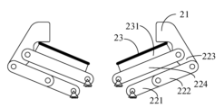
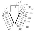
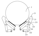
- FIG. 9 is a schematic diagram of an equivalent structure of a clamping jaw assembly of a gripping device in another embodiment of the present application.
- 10a-10b are equivalent schematic diagrams of the working states of the clamping jaw assembly of the grasping device shown in FIG. 9 in the first grasping mode and the second grasping mode.
- FIG. 11 is a schematic structural diagram of a gripping device in a first gripping mode in another embodiment of the present application.
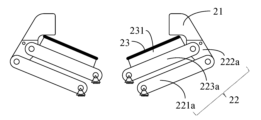
- FIG. 12 is a schematic diagram of the equivalent structure of the clamping jaw assembly of the grasping device shown in FIG. 11 in the second grasping mode.
- FIG. 13 is a schematic diagram of the robot structure in one embodiment of the present application.
- the term "and/or" is only a description of the association relationship of associated objects, indicating that three relationships may exist.
- a and/or B can represent: A exists alone, A and B exist at the same time, and B exists alone.
- the character "/" in this article generally indicates that the associated objects before and after are in an "or" relationship.
- multiple refers to more than two (including two).
- multiple groups refers to more than two groups (including two groups), and “multiple pieces” refers to more than two pieces (including two pieces).
- robots with grasping devices are widely used in many fields such as industrial manufacturing and logistics transportation.
- industrial manufacturing components are grasped and installed by manipulators
- field of logistics objects are grasped and moved by manipulators.
- manipulators in industrial manufacturing use mechanical fingers similar to human fingers to grasp components, which can achieve high precision and reliability, but this grasping method is limited by the stroke length of the mechanical fingers and cannot grasp larger objects.
- due to the large clamping force of the mechanical fingers objects that are easily deformed or fragile may be damaged. For such large or changeable and fragile components, it may be necessary to configure different types of robots, which increases the complexity of automated industrial manufacturing and increases costs.
- the grasping device includes a housing and at least two clamping claw assemblies, and the at least two clamping claw assemblies are used to cooperate with each other under the drive of a driving device to grasp the target object.
- Each of the clamping claw assemblies includes: a fingertip for clamping the target object; a connecting rod assembly, a first end of which is connected to the fingertip and a second end is rotatably connected to the housing; and an attachment assembly, which is arranged on the side of the connecting rod assembly facing the target object to be grasped.
- the attachment assembly is used to contact the surface of the target object to be grasped by adhesion and/or adsorption to achieve a grasping operation.
- the grasping device can switch between a first grasping mode and a second grasping mode, wherein in the first grasping mode, the grasping device clamps the target object by each of the fingertips. In the second grasping mode, the grasping device adheres and/or adsorbs the target object by each of the attachment assemblies to achieve a grasping operation. In this way, the grasping device can switch between different grasping modes for different usage scenarios.
- the inventive concept of the present application is described in detail below in conjunction with various embodiments.
- the gripping device disclosed in the various embodiments of the present application can be applied to, but not limited to, manipulators or robots in the fields of industrial manufacturing, logistics and transportation.
- the various jaw assemblies of the gripping device cooperate with each other to achieve the gripping action under the drive of the driving device.
- there is no restriction on the driving method of each of the jaw assemblies as long as each jaw assembly can achieve the opening and closing action and cooperate with each other to complete the gripping action.
- each of the jaws can be driven by a plurality of linked connecting rods to achieve the opening and closing action, or it can be driven by a tendon to achieve the opening and closing action.
- Tendon drive is a prior art and will not be described in detail here.
- the present application is mainly described below by taking the example of a grasping device driving the jaw assembly to open and close through multiple linked connecting rods to achieve grasping, in combination with various embodiments.
- the grasping device 1 includes a housing 10, at least two clamping jaw assemblies 20 and a driving device 30, and the at least two clamping jaw assemblies 20 are used to cooperate with each other under the drive of the driving device 30 to grasp the target object.
- Each of the clamping jaw assemblies 20 includes a fingertip 21, a connecting rod assembly 22 and an attachment assembly 23.
- the fingertip 21 is used to clamp the target object
- the first end of the connecting rod assembly 22 is connected to the fingertip 21, and the second end is rotatably connected to the housing 10.
- the attachment assembly 23 is at least arranged on one side of the connecting rod assembly 22 facing the target object to be grasped (or the inner side of the clamping jaw assembly), and is used to contact the surface of the target object to be grasped by adsorption and/or adhesion to achieve the grasping of the target object.
- the grasping device 1 can switch between a first grasping mode and a second grasping mode. In the first grasping mode (hereinafter also referred to as the fingertip grasping mode), the grasping device 1 cooperates with each of the fingertips 21 to clamp the target object. In the second grasping mode (hereinafter also referred to as the attachment grasping mode), the grasping device 1 implements a grasping operation by cooperating with each of the attachment components to adhere to and/or absorb the target object.
- the grasping device 1 has different grasping modes.
- the fingertip grasping mode high-precision grasping can be achieved by the fingertips, for example, smaller components at specific positions can be grasped by the fingertips.
- the attachment grasping mode larger or fragile, easily deformable target objects can be grasped by adsorption force and/or adhesion force, and the object can be grasped under the premise of applying the minimum squeezing force to the target object, which is not easy to cause damage to the target object and is not limited by the travel range of the clamping jaw device.
- the grasping device 1 can switch different grasping modes for different usage scenarios, which can reduce the cost and complexity of the assembly line in the industrial manufacturing or logistics and transportation fields and improve the grasping efficiency.
- the number of the clamping jaw assemblies 20 can be set according to actual needs, and the structure of each of the clamping jaw assemblies 20 can be the same.
- the structure of one of the clamping jaw assemblies will be described below as an example.
- each of the clamping jaw assemblies 20 includes a fingertip 21, a connecting rod assembly 22 having four connecting rods, and an attaching assembly 23.
- Each of the clamping jaw assemblies 20 switches between the first grasping mode and the second grasping mode by adjusting the positional relationship of the four connecting rods, and switches between the first state and the second state of each of the fingertips 21.
- each of the connecting rod assemblies 221 includes a first connecting rod 221, a second connecting rod 222, a third connecting rod 223, and a fourth connecting rod 224.
- the first end of the first connecting rod 221 is rotatably connected to the housing 10, and the second end of the first connecting rod 221 is rotatably connected to the first end of the second connecting rod 222.
- the second end of the second connecting rod 222 is rotatably connected to the first end of the third connecting rod 223.
- the third connecting rod 223 is fixedly connected to the fingertip 21, and in some embodiments, the third connecting rod 223 can be integrally formed with the fingertip 21.
- the first end of the fourth connecting rod 224 is rotatably connected to the second end of the third connecting rod 223, and the second end of the fourth connecting rod 224 is rotatably connected to the housing 10.
- the driving device 30 is configured to drive the first end of the first connecting rod 221 to rotate, thereby driving the clamping jaw assemblies 20 to approach or move away from each other.
- the first connecting rod 221 and the second connecting rod 222 are locked in the same straight line and parallel to the fourth connecting rod 221, and the sum of the lengths of the first connecting rod 221 and the second connecting rod 222 (i.e., the distance from the first end of the first connecting rod 221 to the second end of the second connecting rod 222 in this case) is equal to the length of the fourth connecting rod 224 (i.e., the distance from the first end to the second end of the fourth connecting rod 224).
- the rod-shaped structure formed by the colinearity of the first connecting rod 221 and the second connecting rod 222, together with the third connecting rod 223, the fourth connecting rod 224 and the shell part, constitutes a parallelogram connecting rod structure, and each fingertip 21 is in the first state, and the first connecting rod 221 or the fourth connecting rod 224 can rotate under the drive of the driving device 30, so that the at least two clamping jaw assemblies 20 move toward each other so that each fingertip 21 approaches or moves away from each other, thereby grasping or releasing the target object.
- the connecting rod assembly 22 further includes a first locking assembly 225 for locking the first connecting rod 221 and the second connecting rod 222 in the same straight line in the fingertip grasping mode.
- the first locking assembly 225 is disposed between the first connecting rod 221 and the second connecting rod 222, and the first locking assembly 225 includes a first elastic member 2251 (refer to FIG. 5a) and a first stopper 2252.
- the first elastic member 2251 can be preloaded and disposed between the first connecting rod 221 and the second connecting rod 222, and is used to provide a torsion force to the first connecting rod 221 and the second connecting rod 222, so that the second connecting rod 222 has a tendency to deflect in a first direction toward the outside of the clamping jaw assembly relative to the first connecting rod 221.
- the direction toward the outside of the clamping jaw assembly i.e., the direction in which the clamping jaw assemblies move away from each other
- the direction toward the inside of the clamping jaw assembly i.e., the direction in which the clamping jaw assemblies move toward each other
- the first elastic member 2251 may be a torsion spring, one end of which is connected to the first connecting rod 221, and the other end of which is connected to the second connecting rod 222.
- the first stopper 2252 is a stopper protruding from one end of the first connecting rod 221 connected to the second connecting rod 222, and is used to limit the rotation range between the first connecting rod 221 and the second connecting rod 222, and prevent the second connecting rod 222 from deflecting toward the first direction relative to the first connecting rod 221.
- the first elastic member 2251 and the first stopper 2252 work together to make the first connecting rod 221 and the second connecting rod 222 in the same straight line in the fingertip grasping mode.
- the first stopper 2252 may also be set on the second connecting rod 222, as long as the relative rotation limit between the first connecting rod 221 and the second connecting rod 222 is achieved.
- the elastic force of the first elastic member 2251 (such as a torque spring) can be set and adjusted according to actual conditions, so that in the process of clamping/releasing the target object in the first grasping mode of the grasping device, the elastic force generated by the first elastic member 2251 is large enough to prevent the second connecting rod 222 from deflecting toward the first direction relative to the first connecting rod 221, and when the grasping device switches to the second grasping mode, the driving device 30 can overcome the elastic force of the first elastic member 2251 without causing damage.
- the first elastic member is a tension spring, one end of which is fixed to the housing 10, and the other end is fixed to the fourth connecting rod 224.
- the tension spring is configured to provide a pulling force to the fourth connecting rod 2224 in the direction of the housing 10 within the range of motion of the grasping device.
- this tension spring makes the fourth connecting rod 224 have a tendency to deflect in the first direction relative to the housing 10. Since the fourth connecting rod 224, the third connecting rod 223 and the second connecting rod 222 are connected in sequence, the fourth connecting rod 224 drives the second connecting rod 222 so that the second connecting rod 222 has a tendency to deflect in the first direction relative to the first connecting rod 221.
- a first stopper 2252 is also provided to prevent the second connecting rod 222 from deflecting in the first direction relative to the first connecting rod 221. Therefore, the tension spring cooperates with the first stopper 2252 to make the first connecting rod 221 and the second connecting rod 222 be in the same straight line in the fingertip grasping mode.
- the first elastic member when the first elastic member is a tension spring, one end of the tension spring is connected to the housing 10, and the other end may also be connected to the second connecting rod 222.
- the tension spring is configured to provide a pulling force toward the housing 10 to the second connecting rod 222 within the range of motion of the grasping device, so that the second connecting rod 222 has a tendency to deflect toward the first direction relative to the first connecting rod 221.
- a first stopper 2252 is also provided to prevent the second connecting rod 222 from deflecting toward the first direction relative to the first connecting rod 221. Therefore, the tension spring cooperates with the first stopper 2252 to make the first connecting rod 221 and the second connecting rod 222 in the same straight line in the fingertip grasping mode.
- first elastic member when the first elastic member is a tension spring, one end of the first elastic member may be disposed on the housing 10 and the other end on the third connecting rod 223.
- first elastic member when the first elastic member is a tension spring, one end of the first elastic member may be disposed on the housing 10 and the other end on the third connecting rod 223. The principle is similar to that of the above two embodiments and will not be repeated here.
- the structure of the clamping jaw assembly in the fingertip grasping mode can be made more stable.
- the relative rotation and limit locking between the first connecting rod 221 and the second connecting rod 222 can also be achieved by a drive motor, gears and other devices arranged at the connection between the two rods.
- the angle between the third connecting rod 223 and the fourth connecting rod 224 is locked at a preset angle, so that the fingertip 21 is in the second state, and the fingertip deflects in the first direction away from each clamping claw assembly relative to the attachment assembly.
- the limit and locking between the first connecting rod 221 and the second connecting rod 222 are invalid (for example, in the example of using a drive motor, the drive motor for locking can be disabled when switching to the second state) or its elastic limit force is overcome, so the first connecting rod 221 and the second connecting rod 222 can rotate relatively freely.
- the third connecting rod 223 and the fourth connecting rod 224 are locked at a position with a smaller angle in the second state, so that the fingertip 21 deflects toward the outside of the clamping claw assembly, that is, the first direction, relative to the attachment assembly 23 compared to the first state.
- the second state when the grasping device 1 grasps the target object through the attachment assembly 23, the fingertip 21 does not touch the target object, avoiding damage to the fragile or volatile target object.
- the angle between the plane of the fingertip 21 for grasping the target object and the plane where the attachment component 23 is located is greater than or equal to 180 degrees.
- the grasping device 1 can grasp the object through the attachment component 23 disposed inside the connecting rod component 22.
- the first connecting rod and the second connecting rod are locked in a colinear state to achieve the first state of the fingertips, and the third connecting rod and the fourth connecting rod are locked at a preset angle to achieve the second state of the fingertips.
- the switching of the grasping mode and the fingertip state is achieved by changing the position of the connecting rods. There is no need to set up an additional driving mechanism, which makes the structure of the grasping device simple and the cost lower.
- the connecting rod assembly 22 further includes a second locking assembly 226 for locking the third connecting rod 223 and the fourth connecting rod 224 at a preset angle in the attachment and grasping mode.
- the second locking assembly 226 includes a first locking element 2261 and a second locking element 2262.
- the first locking element 2261 is disposed on the fourth connecting rod 224
- the second locking element 2262 is disposed on the third connecting rod 223.
- the first locking element 2261 and the second locking element 2262 are configured to cooperate to lock or release the third connecting rod 223 and the fourth connecting rod 224.
- the angle between the third connecting rod 223 and the fourth connecting rod 224 is the preset angle
- the first locking element 2261 and the second locking element 2262 cooperate to lock the relative position between the third connecting rod 223 and the fourth connecting rod 224.
- the first locking element 2261 and the second locking element 2262 are both magnets.
- the third connecting rod 223 and the fourth connecting rod 224 are locked at the preset angle by the attraction between the two magnets.
- At least one of the third connecting rod 223 and the fourth connecting rod 224 is provided with a mounting groove 2263 for accommodating the magnet and adjusting the position of the magnet.
- the mounting groove 2263 can be a cavity, and the magnet is installed in the cavity.
- An adjusting element for adjusting the position of the magnet in the mounting groove 2263 can also be provided in the mounting groove 2263.
- first locking element 2261 and the second locking element 2262 may also be a pair of snap-fit structures, which lock the third connecting rod 223 and the fourth connecting rod 224 at the preset angle by snap-fitting.
- the second locking assembly 226 can be considered as passive locking by magnet attraction and snap fastening.
- the magnitude of the locking force and the magnitude of the force required to release the passive locking can be configured according to actual conditions, as long as the third connecting rod 223 and the fourth connecting rod 224 can be kept locked in the second grabbing mode and can be released during the switching process from the second grabbing mode to the first grabbing mode.
- the specific mode switching process example is described below.
- the second locking assembly 226 may also be an electromagnetic clutch disposed in the third connecting rod 223 or the fourth connecting rod 224.
- the electromagnetic clutch In the fingertip grasping mode, the electromagnetic clutch is in a power-off state, and the third connecting rod 223 and the fourth connecting rod 224 can rotate freely.
- the electromagnetic clutch In the attachment grasping mode, the electromagnetic clutch is energized, and the third connecting rod 223 and the fourth connecting rod 224 are locked at the preset angle.
- the relative rotation and limit locking between the third connecting rod 223 and the fourth connecting rod 224 may also be achieved by a drive motor, gears, or other devices disposed at the connection between the two rods. The present application does not specifically limit the locking method between the two connecting rods.
- the locking method of the second locking component 226 through the electromagnetic clutch or the drive motor can be considered as active locking.
- the corresponding processor can send locking and unlocking instructions to the second locking component 226 according to the operating needs of the grasping device.
- the housing 10 further includes a first limiting element 11 and a second limiting element 12, which are respectively arranged on both sides of the fourth connecting rod 224, and are used to limit the rotation range of the fourth connecting rod 224 in the corresponding direction.
- the first limiting element 11 is arranged on the housing 10 near the side of the fourth connecting rod 224 toward the first connecting rod 221, and is used to limit the rotation range of the fourth connecting rod 224 in the first direction when the clamping jaw assemblies 20 rotate in the first direction away from each other.
- the second limiting element 12 is arranged on the housing 10 near the side of the connecting rod 224 toward the attachment assembly 23, and is used to limit the rotation range of the fourth connecting rod 224 in the second direction when the clamping jaw assemblies 20 move in the second direction close to each other.
- the first limiting element 11 and the second limiting element 22 can be grooves or protruding blocks that play a limiting role, etc., as long as they can play a limiting role, the specific structure is not limited.
- the grabbing device can achieve mode switching through a simple mechanical structure without the need for an additional driving device, which has a simple structure and lower cost. The specific mode switching process is described below.
- the driving device 30 is disposed in the housing 10, and is used to drive the first connecting rod 221 and/or the fourth connecting rod 224 to rotate, so as to realize the opening and closing of each clamping jaw assembly 20, and to realize the grasping and releasing actions.
- the driving device 30 may include any mechanism such as a motor that can drive the clamping jaw assembly 20 to rotate, which will not be described in detail here.
- the driving device driving the first connecting rod 221 is taken as an example for explanation.
- the working process of the gripping device 1 is exemplarily described below with reference to FIGS. 5 a - 8 c .
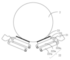
- Figures 5a-5b show the movement process of the at least two clamping jaw assemblies 20 grasping the target object 2 in the fingertip grasping mode.
- the first connecting rod 221 and the second connecting rod 222 are locked in the state of being in the same straight line, and the other connecting rods can rotate freely, and the second locking assembly 226 does not perform a locking action.
- the grasping plane of each fingertip 21 contacting the target object always maintains the same direction during the process of each clamping jaw assembly 20 approaching or moving away from each other, that is, it is in the first state.
- FIG. 5a shows the state of at least two clamping jaw assemblies 20 when they are opened in the fingertip grasping mode.
- the first connecting rod 221 or the fourth connecting rod 224 rotates under the drive of the driving device 30, so that each clamping jaw assembly 20 moves toward each other.
- each fingertip 21 moves to the target object and clamps the target object.
- the attachment assembly 23 can be prevented from contacting the target object.
- FIG. 6 a - FIG 6 c are equivalent schematic diagrams of the process of the grasping device 1 switching from the fingertip grasping mode to the sticking grasping mode.
- each clamping jaw assembly 20 gradually opens, and when the fourth connecting rod 224 rotates to the first limiting element 11, it is restricted by the first limiting element 11 and cannot continue to rotate.
- the driving device 30 continues to drive the first connecting rod 221 to rotate, so that the first connecting rod 221 and the second connecting rod 222 break through the locking of the first locking assembly 225 and rotate relative to each other, and at the same time drives the third connecting rod 223 to continue to rotate, so that the third connecting rod 223 deflects toward the first direction relative to the fourth connecting rod 224, as shown in FIG6b.
- the clamping jaw assembly 20 rotates until the third connecting rod 223 and the fourth connecting rod 224 move to the preset angle and are locked by the second locking assembly 226, as shown in FIG6c, and the grasping device 1 switches to the attachment grasping mode.
- the fingertips 21 of each gripper assembly 20 are in the second state.
- the angle between the plane of the target object grasped by the fingertips 21 and the plane where the attachment assembly 23 is located is relatively large (for example, equal to or greater than 180 degrees). In this way, when the grasping device 1 grasps the target object through the attachment assembly 23, the fingertips 21 do not touch the target object.
- FIG. 7 a - 7 b illustrate the movement process of each clamping jaw assembly 20 in the attachment grasping mode.
- FIG7a shows the state of each clamping jaw assembly 20 when it is open in the attachment grasping mode.
- each clamping jaw assembly 20 rotates in a direction close to each other under the drive of the driving device 30, as shown in FIG7b, until the attachment assembly 23 attaches or absorbs the target object 2.
- the angle between the third connecting rod 223 and the fourth connecting rod 224 is always maintained at the preset angle, and the relative position of the two remains unchanged.
- FIG. 3 Please refer to FIG. 3 , FIG. 4 and FIG. 8 a - 8 c , and the following describes the process of switching the grasping device 1 from the sticking grasping mode to the fingertip grasping mode.
- each jaw assembly 20 In the attachment grasping mode, as the driving device 30 drives each jaw assembly 20 to continuously rotate in a direction approaching each other, as shown in Figures 8a-8b, each jaw assembly 20 gradually closes, and when the fourth connecting rod 224 rotates to the second limiting element 12, it is restricted by the second limiting element 12 and cannot continue to rotate. At this time, the driving device 30 drives the first connecting rod 221 of each jaw assembly to continue to rotate in the second direction approaching each other, and the third connecting rod 223 is driven to continue to rotate so that the lock between the third connecting rod 223 and the fourth connecting rod 224 is released under the driving force of the driving device 30.
- the first connecting rod 221 and the second connecting rod 222 restore the state of the grasping device in the first grasping mode under the action of the first locking component 225, that is, the first connecting rod 221 and the second connecting rod 222 are in the same straight line and are locked by the first locking component 225, as shown in Figure 8c.
- the second locking component 226 releases the lock on the relative position between the third connecting rod 223 and the fourth connecting rod 224, and the grasping device 1 switches from the attachment grasping mode to the fingertip grasping mode.
- the switching between the fingertip grasping mode and the attachment grasping mode can be executed by responding to the user's switching instruction and controlling the driving device 30 through a software program.
- the grasping device provided in this embodiment, by arranging an attachment component on the inner side of the connecting rod component, enables a grasping device to realize precise grasping in the fingertip grasping mode, and to grasp large, fragile or changeable objects in the attachment grasping mode, and the two grasping modes will not affect each other, and can adapt to more scenarios.
- the switching of the two modes is realized, thereby realizing the switching of the two grasping modes.
- the structure is simple, and no additional controller or driver is required, which reduces the complexity of the system.
- the change of the fingertip position can avoid the fingertips from damaging the target object in the attachment grasping mode.
- the gecko-like adhesive material film with constant tension the length of the attachment component toward the target object can be adjusted, so that larger target objects can be grasped, and a more reliable wrapping force can be provided.
- the attachment assembly 23 is arranged on the side of the connecting rod assembly 22 facing the target object to be grasped when grasping the target object, that is, the side opposite to at least two clamping jaw assemblies 20 (the inner side of the connecting rod assembly 22 in the figure), and is used to grasp the target object by adsorption or adhesion in the attachment grasping mode.
- the housing 10 also includes a first fixing member 13 and a second fixing member 14, and the attachment assembly 23 is connected between the housing 10 and the fingertip 21 through the first fixing member 13 and the second fixing member 14.
- the attachment component 23 is a strip-shaped gecko adhesive material film, and the gecko adhesive material film is arranged along the length direction of the connecting rod component 22.
- the gecko adhesive material is an adhesive material inspired by the gecko and designed to imitate the structure of the gecko's foot.
- the surface of the gecko adhesive material film is provided with a plurality of micro-wedge structures, which can adhere to the surface of the object through intermolecular interactions (such as van der Waals forces).
- the grasping operation is achieved by adhering the gecko adhesive material film to the surface of the target object. Since the gecko adhesive material film is a known technology, it will not be described in detail here.
- the first end of the gecko-like adhesive material film is fixed to the housing 10 near the fourth connecting rod 224 through the first fixing member 13, and the second end is connected to one end of the connecting rod assembly 22 near the fingertip 21 through the second fixing member 14.
- at least one of the first fixing member 13 and the second fixing member 14 can provide a substantially constant loading force for the gecko-like adhesive material film, and the direction of the loading force is the length direction of the connecting rod assembly, so that the gecko-like adhesive material film can be extended and retracted with the opening and closing of the clamping jaw assembly 20, and the attachment assembly is always in a tensioned state during the movement of the clamping jaw assembly.
- the first fixing member 13 is disposed on the housing 10 and between the at least two clamping jaw assemblies 20, and is used to connect the first end of the gecko-like adhesive material film.
- the fingertip 21 is provided with a first roller 227
- the fourth connecting rod 224 is provided with a second roller 228.
- the second fixing member 14 is disposed between the corresponding clamping jaw assembly 20 and the first fixing member 13. The first end of the gecko-like adhesive material film is connected to the first fixing member 13, and the main body of the gecko-like adhesive material passes through the first roller 227 and the second roller 228 in sequence, and the second end is connected to the second fixing member 14.
- the second fixing member 14 provides a substantially constant loading force for the gecko-like adhesive material 23.
- the gecko-like adhesive material film also has a larger elastic space, which is beneficial for protecting target objects that are easily deformed or fragile.
- the basically constant loading force can be achieved through an elastic member (such as a constant force spring) or through a rotating shaft that can provide a constant loading force.
- the basically constant loading force can keep the attachment component 23 in a tensioned state during the movement of the clamping jaw component, thereby preventing the gecko-like adhesive material film from wrinkling during the expansion and contraction process, thereby providing a more reliable wrapping force/adhesion force for the target object.
- the second fixing member 14 can also be set at one end of the fourth connecting rod 224 close to the fingertip 21, and at least one of the first fixing member 13 and the second fixing member 14 provides a basically constant loading force for the gecko-like adhesive material film without the need for the aforementioned two rollers.
- the attachment component 23 can be correspondingly arranged on each of the clamping jaw components 20. If the number of the clamping jaw components 20 is large, the attachment component 20 can also be arranged only on some of the clamping jaw components 20. For example, when the grasping device 1 has four clamping jaw components, the attachment component can be arranged only on two of the clamping jaw components. The specific arrangement can be based on actual needs.
- the attachment component 23 may also be directly attached to the side of the connected rod component 22 facing the target object.
- the structure of the connecting rod assembly 22 is similar to that in the embodiment shown in Figures 1-4, and also includes a first connecting rod 221, a second connecting rod 222, a third connecting rod 223 and a fourth connecting rod 224, and the attachment assembly 23 is attached to the side of the fourth connecting rod 223 facing the target object. Since the attachment assembly 23 is directly attached to the fourth connecting rod 224, it is not necessary to set a first fixing member, a second fixing member, a first roller and a second roller for fixing the attachment assembly 23 on the housing 10, so that the structure of the grasping device is further simplified.
- the working process and switching process of the fingertip grasping mode and the attachment grasping mode can refer to the above-mentioned embodiments, which will not be repeated here.
- a pad 231 is further provided between the attachment assembly 23 and the connecting rod assembly 22.
- the gecko-like adhesive material is fixed on the pad 231, and then fixed to the fourth connecting rod 224 through the pad 231.
- the pad 231 can be made of a flexible and deformable material, such as rubber, foam, etc.
- the attachment component 23 may also be a material with adhesion function such as a gecko-like adhesive material directly coated on the connecting rod component.
- the attachment component 23 may also be one or more vacuum adsorption devices, such as suction cups, disposed on the connecting rod component 22.
- the attachment component 23 may grasp the target object by the suction force of the suction cup in the attachment grasping mode.
- attachment component 23 in the present application can also be any other structure or material that can grasp and release the target object by adsorption or adhesion.
- the present application does not limit this. As long as it can grasp the object by adsorption or adhesion, it is within the protection scope of the present application.
- FIGS 11-12 are schematic diagrams of the structure of a gripping device in another embodiment of the present application.
- each of the fingertips 21 is rotatably connected to the first end of the corresponding connecting rod assembly 22.
- each of the fingertips 21 is in the first state, as shown in FIG11 , and the gripping plane of each fingertip 21 gripping the target object always keeps the same direction during the process of the clamping jaw assemblies approaching and moving away from each other.
- the fingertips 21 of each clamping jaw assembly 20 are arranged relative to each other and cooperate with each other to clamp the target object.
- the gripping device 1 By rotating the fingertips 21 in a direction away from the attachment assembly 23, the gripping device 1 can be switched from the fingertip gripping mode to the attachment gripping mode, as shown in FIG12 , at this time, the fingertips are in the second state, that is, each of the fingertips is deflected toward the first direction relative to the attachment assembly, so that when the gripping device 1 grips the target object in the attachment gripping mode, the fingertips 21 do not contact the target object.
- the fingertip 21 can be rotatably connected to the first end of the connecting rod assembly 22 via a hinge.
- the present application does not specifically limit the method of driving the fingertip 21 to rotate.
- the fingertip 21 can be rotated to the first state and the second state manually, or driven to rotate to the first state and the second state by a driving device such as a driving motor.
- each of the connecting rod assemblies 22 may include three connecting rods that are rotatably connected in sequence, namely, a first connecting rod 221a, a second connecting rod 222a, and a third connecting rod 223a.
- the free end of the first connecting rod 221a and the free end of the third connecting rod 223a are rotatably connected to the housing 10.
- the first connecting rod 221a, the second connecting rod 222a, and the third connecting rod 223a form a parallelogram structure with the housing 10.
- the fingertip 21 is rotatably connected to one end of the second connecting rod 222a close to the third connecting rod 223a.
- the attachment assembly 23 is fixedly arranged on the side of the third connecting rod 223a facing the target object to be grasped.
- the installation method of the attachment assembly 23 can refer to the above-mentioned embodiments, which will not be repeated here.
- each of the fingertips 21 switches between the first state and the second state by rotating, so that the design of the connecting rod assembly 22 is simpler.
- the fingertip 21 may also be detachably connected to the first end of the connecting rod assembly 22.
- the fingertip 21 When in the fingertip grasping mode, the fingertip 21 is mounted on one end of the connecting rod assembly 22.
- the fingertip 21 may be manually removed.
- the fingertip 21 may be detachably mounted on the connecting rod assembly 22 by means of screws, buckles, etc., or may be detachably mounted on the connecting rod assembly 22 by means of plugging, etc., and this application does not impose any specific restrictions on this.
- each of the fingertips 21 does not change state in the first grasping mode and the second grasping mode.
- the present application also provides a robot 3.
- the robot 3 may include at least one connecting member 31 and at least one grasping device 32.
- the robot 3 can be used to grasp or capture a target object.
- the grasping device 32 can be any grasping device of the embodiment described above.
- the structure shown in FIG13 is only an exemplary embodiment of the robot 3.
- the robot 3 may include more or fewer components.
- the robot may also include input and output devices, network access devices, communication buses, processors, memories, actuators, and sensors. These additional components can implement a control system, such as the switching instructions discussed above.
- the robot 3 may also include a processor and a memory storing instructions, which, when executed by the processor, enables the processor to implement a control system.
- the memory may also store instructions, which, when executed by the processor, causes the processor to activate or deactivate the grasping device 32 in order to capture or release the target object to be grasped.
Landscapes
- Engineering & Computer Science (AREA)
- Mechanical Engineering (AREA)
- Robotics (AREA)
- Manufacturing & Machinery (AREA)
- Microelectronics & Electronic Packaging (AREA)
- Manipulator (AREA)
Abstract
Priority Applications (4)
| Application Number | Priority Date | Filing Date | Title |
|---|---|---|---|
| EP22966252.3A EP4624119A4 (fr) | 2022-11-25 | 2022-11-25 | Appareil de préhension, et robot ayant un appareil de préhension |
| JP2025530585A JP2025536828A (ja) | 2022-11-25 | 2022-11-25 | 把持装置及び把持装置を有するロボット |
| US18/555,792 US20250073919A1 (en) | 2022-11-25 | 2022-11-25 | Gripping device and robot having the same |
| PCT/CN2022/134404 WO2024108564A1 (fr) | 2022-11-25 | 2022-11-25 | Appareil de préhension, et robot ayant un appareil de préhension |
Applications Claiming Priority (1)
| Application Number | Priority Date | Filing Date | Title |
|---|---|---|---|
| PCT/CN2022/134404 WO2024108564A1 (fr) | 2022-11-25 | 2022-11-25 | Appareil de préhension, et robot ayant un appareil de préhension |
Publications (1)
| Publication Number | Publication Date |
|---|---|
| WO2024108564A1 true WO2024108564A1 (fr) | 2024-05-30 |
Family
ID=91195055
Family Applications (1)
| Application Number | Title | Priority Date | Filing Date |
|---|---|---|---|
| PCT/CN2022/134404 Ceased WO2024108564A1 (fr) | 2022-11-25 | 2022-11-25 | Appareil de préhension, et robot ayant un appareil de préhension |
Country Status (4)
| Country | Link |
|---|---|
| US (1) | US20250073919A1 (fr) |
| EP (1) | EP4624119A4 (fr) |
| JP (1) | JP2025536828A (fr) |
| WO (1) | WO2024108564A1 (fr) |
Cited By (2)
| Publication number | Priority date | Publication date | Assignee | Title |
|---|---|---|---|---|
| CN118664628A (zh) * | 2024-05-31 | 2024-09-20 | 华南理工大学 | 一种电驱丝杆夹持锁定机构 |
| CN119553972A (zh) * | 2024-11-29 | 2025-03-04 | 国能神东煤炭集团有限责任公司 | 一种机械手、装置及钻机系统 |
Families Citing this family (1)
| Publication number | Priority date | Publication date | Assignee | Title |
|---|---|---|---|---|
| JP2026511857A (ja) * | 2023-04-07 | 2026-04-14 | シャンハイ・フレクシブ・ロボティクス・テクノロジー・カンパニー・リミテッド | 把持装置及びロボット |
Citations (13)
| Publication number | Priority date | Publication date | Assignee | Title |
|---|---|---|---|---|
| JP2010082748A (ja) * | 2008-09-30 | 2010-04-15 | Fanuc Ltd | ワーク把持装置 |
| CN203752160U (zh) * | 2014-03-25 | 2014-08-06 | 甘肃农业大学 | 快速欠驱动吸附性采摘机械手 |
| CN107009381A (zh) * | 2017-05-24 | 2017-08-04 | 成都众智优学教育咨询有限公司 | 一种机械臂的回转型连接件 |
| CN108453778A (zh) * | 2018-02-05 | 2018-08-28 | 中国科学技术大学 | 一种具有多种抓取模式的欠驱动真空吸盘手爪 |
| JP2019063886A (ja) * | 2017-09-28 | 2019-04-25 | 国立研究開発法人産業技術総合研究所 | ロボットハンドの指の駆動機構、および、その駆動機構を具備する指を備えるロボットハンド |
| CN110730707A (zh) * | 2018-08-22 | 2020-01-24 | 上海非夕机器人科技有限公司 | 具有合成纤维胶的机器人和抓取器 |
| DE102018124920A1 (de) * | 2018-10-09 | 2020-04-09 | J. Schmalz Gmbh | Sauggreifvorrichtung und Verfahren zum Betreiben einer solchen Sauggreifvorrichtung |
| KR20200080778A (ko) * | 2018-12-27 | 2020-07-07 | 재단법인 제조혁신기술원 | 소프트 그리퍼 및 그 그리퍼의 구동방법 |
| CN213674178U (zh) * | 2020-09-25 | 2021-07-13 | 苏州市金盾自动化系统有限公司 | 一种多工件抓取机构及导电pad组装设备 |
| CN113246161A (zh) * | 2021-05-31 | 2021-08-13 | 吉林大学 | 一种多功能行李抓取折叠机械手 |
| WO2021171006A1 (fr) * | 2020-02-27 | 2021-09-02 | Dyson Technology Limited | Main de robot |
| CN113815005A (zh) * | 2021-11-22 | 2021-12-21 | 季华实验室 | 一种可转换的机械臂末端夹具及机械臂 |
| JP2022109172A (ja) * | 2021-01-14 | 2022-07-27 | 株式会社東芝 | 保持装置および搬送装置 |
Family Cites Families (10)
| Publication number | Priority date | Publication date | Assignee | Title |
|---|---|---|---|---|
| JPS5924981A (ja) * | 1982-07-29 | 1984-02-08 | 株式会社東芝 | ロボツトハンド |
| JP2011131341A (ja) * | 2009-12-25 | 2011-07-07 | Sony Corp | 把持装置 |
| CA2856622C (fr) * | 2011-11-25 | 2017-01-10 | Robotiq Inc. | Appareil de prehension comprenant un doigt mecanique sous-actionne a deux degres de liberte permettant la prehension par enserrage et par pincement |
| JP5966956B2 (ja) * | 2013-02-05 | 2016-08-10 | トヨタ自動車株式会社 | ロボットハンド |
| DE102014223118B4 (de) * | 2014-11-12 | 2021-04-29 | Schunk Gmbh & Co. Kg Spann- Und Greiftechnik | Greifvorrichtung |
| JP6739935B2 (ja) * | 2015-12-25 | 2020-08-12 | 株式会社東芝 | 駆動装置 |
| DE102018100621B4 (de) * | 2018-01-12 | 2021-12-23 | Schunk Gmbh & Co. Kg Spann- Und Greiftechnik | Greifverfahren und Greifvorrichtung zum Greifen von insbesondere folien- oder membranartigen Objekten |
| JP2020066084A (ja) * | 2018-10-24 | 2020-04-30 | 学校法人早稲田大学 | グリッパ |
| US20220203556A1 (en) * | 2019-04-22 | 2022-06-30 | The Governing Council Of The University Of Toronto | System for controllably establishing adhesion or friction with an external body |
| CN115122384B (zh) * | 2022-07-05 | 2025-02-11 | 北京工业大学 | 一种拾取装置及拾取臂机构 |
-
2022
- 2022-11-25 WO PCT/CN2022/134404 patent/WO2024108564A1/fr not_active Ceased
- 2022-11-25 JP JP2025530585A patent/JP2025536828A/ja active Pending
- 2022-11-25 EP EP22966252.3A patent/EP4624119A4/fr active Pending
- 2022-11-25 US US18/555,792 patent/US20250073919A1/en active Pending
Patent Citations (13)
| Publication number | Priority date | Publication date | Assignee | Title |
|---|---|---|---|---|
| JP2010082748A (ja) * | 2008-09-30 | 2010-04-15 | Fanuc Ltd | ワーク把持装置 |
| CN203752160U (zh) * | 2014-03-25 | 2014-08-06 | 甘肃农业大学 | 快速欠驱动吸附性采摘机械手 |
| CN107009381A (zh) * | 2017-05-24 | 2017-08-04 | 成都众智优学教育咨询有限公司 | 一种机械臂的回转型连接件 |
| JP2019063886A (ja) * | 2017-09-28 | 2019-04-25 | 国立研究開発法人産業技術総合研究所 | ロボットハンドの指の駆動機構、および、その駆動機構を具備する指を備えるロボットハンド |
| CN108453778A (zh) * | 2018-02-05 | 2018-08-28 | 中国科学技术大学 | 一种具有多种抓取模式的欠驱动真空吸盘手爪 |
| CN110730707A (zh) * | 2018-08-22 | 2020-01-24 | 上海非夕机器人科技有限公司 | 具有合成纤维胶的机器人和抓取器 |
| DE102018124920A1 (de) * | 2018-10-09 | 2020-04-09 | J. Schmalz Gmbh | Sauggreifvorrichtung und Verfahren zum Betreiben einer solchen Sauggreifvorrichtung |
| KR20200080778A (ko) * | 2018-12-27 | 2020-07-07 | 재단법인 제조혁신기술원 | 소프트 그리퍼 및 그 그리퍼의 구동방법 |
| WO2021171006A1 (fr) * | 2020-02-27 | 2021-09-02 | Dyson Technology Limited | Main de robot |
| CN213674178U (zh) * | 2020-09-25 | 2021-07-13 | 苏州市金盾自动化系统有限公司 | 一种多工件抓取机构及导电pad组装设备 |
| JP2022109172A (ja) * | 2021-01-14 | 2022-07-27 | 株式会社東芝 | 保持装置および搬送装置 |
| CN113246161A (zh) * | 2021-05-31 | 2021-08-13 | 吉林大学 | 一种多功能行李抓取折叠机械手 |
| CN113815005A (zh) * | 2021-11-22 | 2021-12-21 | 季华实验室 | 一种可转换的机械臂末端夹具及机械臂 |
Non-Patent Citations (1)
| Title |
|---|
| See also references of EP4624119A4 * |
Cited By (2)
| Publication number | Priority date | Publication date | Assignee | Title |
|---|---|---|---|---|
| CN118664628A (zh) * | 2024-05-31 | 2024-09-20 | 华南理工大学 | 一种电驱丝杆夹持锁定机构 |
| CN119553972A (zh) * | 2024-11-29 | 2025-03-04 | 国能神东煤炭集团有限责任公司 | 一种机械手、装置及钻机系统 |
Also Published As
| Publication number | Publication date |
|---|---|
| JP2025536828A (ja) | 2025-11-07 |
| EP4624119A1 (fr) | 2025-10-01 |
| EP4624119A4 (fr) | 2026-01-21 |
| US20250073919A1 (en) | 2025-03-06 |
Similar Documents
| Publication | Publication Date | Title |
|---|---|---|
| WO2024108564A1 (fr) | Appareil de préhension, et robot ayant un appareil de préhension | |
| JP6811267B2 (ja) | 柔軟劣駆動把持具 | |
| US6626476B1 (en) | Robotic gripper apparatus | |
| US9004559B2 (en) | Compliant underactuated grasper | |
| CN110730707B (zh) | 具有合成纤维胶的机器人和抓取器 | |
| CN105813811B (zh) | 机械手机构 | |
| US20200198157A1 (en) | Gripping device | |
| US20200206950A1 (en) | Finger mechanism and humanoid hand incorporating same finger mechanism | |
| CN104802180B (zh) | 欠驱动拟人三指机械手 | |
| US20220063112A1 (en) | Robot hand and picking system | |
| CN110900641B (zh) | 一种平夹自适应三指欠驱动机器人手 | |
| JP2011240422A (ja) | ロボットハンド、およびロボット | |
| CN109571539B (zh) | 可控力的快速抓取杆簇自适应机器人手装置 | |
| JP2015112651A (ja) | ハンド機構 | |
| CN105881565A (zh) | 四连杆平夹自适应机器人手指装置 | |
| CN115674251B (zh) | 抓取装置及具有抓取装置的机器人 | |
| CN115151388B (zh) | 机器人手 | |
| CN105798945B (zh) | 单环柔性件平夹自适应机器人手指装置 | |
| CN105583838A (zh) | 流体式接触抓取联动自适应机器人手指装置 | |
| CN108115715A (zh) | 差动连杆反向传动增效平夹自适应机器人手指装置 | |
| CN115210050B (zh) | 机器人手 | |
| US20250073928A1 (en) | Gripping device and robot having the same | |
| CN116277097B (en) | Grabbing device and robot with grabbing device | |
| CN115151387B (zh) | 机器人手 | |
| CN116277097A (zh) | 抓取装置及具有抓取装置的机器人 |
Legal Events
| Date | Code | Title | Description |
|---|---|---|---|
| WWE | Wipo information: entry into national phase |
Ref document number: 18555792 Country of ref document: US |
|
| 121 | Ep: the epo has been informed by wipo that ep was designated in this application |
Ref document number: 22966252 Country of ref document: EP Kind code of ref document: A1 |
|
| WWP | Wipo information: published in national office |
Ref document number: 18555792 Country of ref document: US |
|
| ENP | Entry into the national phase |
Ref document number: 2025530585 Country of ref document: JP Kind code of ref document: A |
|
| WWE | Wipo information: entry into national phase |
Ref document number: 2025530585 Country of ref document: JP |
|
| WWE | Wipo information: entry into national phase |
Ref document number: 2022966252 Country of ref document: EP |
|
| NENP | Non-entry into the national phase |
Ref country code: DE |
|
| ENP | Entry into the national phase |
Ref document number: 2022966252 Country of ref document: EP Effective date: 20250625 |
|
| WWP | Wipo information: published in national office |
Ref document number: 2022966252 Country of ref document: EP |