WO2024110102A1 - Capteur de position magnétique sans contact angulaire ou linéaire de haute précision - Google Patents
Capteur de position magnétique sans contact angulaire ou linéaire de haute précision Download PDFInfo
- Publication number
- WO2024110102A1 WO2024110102A1 PCT/EP2023/076591 EP2023076591W WO2024110102A1 WO 2024110102 A1 WO2024110102 A1 WO 2024110102A1 EP 2023076591 W EP2023076591 W EP 2023076591W WO 2024110102 A1 WO2024110102 A1 WO 2024110102A1
- Authority
- WO
- WIPO (PCT)
- Prior art keywords
- probes
- angular
- position sensor
- sensor
- pair
- Prior art date
- Legal status (The legal status is an assumption and is not a legal conclusion. Google has not performed a legal analysis and makes no representation as to the accuracy of the status listed.)
- Ceased
Links
Images


Classifications
-
- G—PHYSICS
- G01—MEASURING; TESTING
- G01D—MEASURING NOT SPECIALLY ADAPTED FOR A SPECIFIC VARIABLE; ARRANGEMENTS FOR MEASURING TWO OR MORE VARIABLES NOT COVERED IN A SINGLE OTHER SUBCLASS; TARIFF METERING APPARATUS; MEASURING OR TESTING NOT OTHERWISE PROVIDED FOR
- G01D5/00—Mechanical means for transferring the output of a sensing member; Means for converting the output of a sensing member to another variable where the form or nature of the sensing member does not constrain the means for converting; Transducers not specially adapted for a specific variable
- G01D5/12—Mechanical means for transferring the output of a sensing member; Means for converting the output of a sensing member to another variable where the form or nature of the sensing member does not constrain the means for converting; Transducers not specially adapted for a specific variable using electric or magnetic means
- G01D5/14—Mechanical means for transferring the output of a sensing member; Means for converting the output of a sensing member to another variable where the form or nature of the sensing member does not constrain the means for converting; Transducers not specially adapted for a specific variable using electric or magnetic means influencing the magnitude of a current or voltage
- G01D5/142—Mechanical means for transferring the output of a sensing member; Means for converting the output of a sensing member to another variable where the form or nature of the sensing member does not constrain the means for converting; Transducers not specially adapted for a specific variable using electric or magnetic means influencing the magnitude of a current or voltage using Hall-effect devices
- G01D5/145—Mechanical means for transferring the output of a sensing member; Means for converting the output of a sensing member to another variable where the form or nature of the sensing member does not constrain the means for converting; Transducers not specially adapted for a specific variable using electric or magnetic means influencing the magnitude of a current or voltage using Hall-effect devices influenced by the relative movement between the Hall device and magnetic fields
-
- G—PHYSICS
- G01—MEASURING; TESTING
- G01B—MEASURING LENGTH, THICKNESS OR SIMILAR LINEAR DIMENSIONS; MEASURING ANGLES; MEASURING AREAS; MEASURING IRREGULARITIES OF SURFACES OR CONTOURS
- G01B7/00—Measuring arrangements characterised by the use of electric or magnetic techniques
- G01B7/003—Measuring arrangements characterised by the use of electric or magnetic techniques for measuring position, not involving coordinate determination
-
- G—PHYSICS
- G01—MEASURING; TESTING
- G01B—MEASURING LENGTH, THICKNESS OR SIMILAR LINEAR DIMENSIONS; MEASURING ANGLES; MEASURING AREAS; MEASURING IRREGULARITIES OF SURFACES OR CONTOURS
- G01B7/00—Measuring arrangements characterised by the use of electric or magnetic techniques
- G01B7/30—Measuring arrangements characterised by the use of electric or magnetic techniques for measuring angles or tapers; for testing the alignment of axes
Definitions
- the present invention relates to the field of contactless, magnetic and/or electromagnetic position sensors, for the precise measurement of an absolute angular or linear position.
- Such sensors make it possible to detect an angular position or a linear displacement with high precision of the order of 0.1% of the total travel, or ⁇ 0.5° for detection carried out over a complete revolution.
- Such systems which can be robust to disturbances and highly precise, are used in particular in the automobile industry and in the robotics industry.
- document FR2893410 proposes to apply to the ratio of the signals delivered by magneto-sensitive detection elements located at the same point, a compensation coefficient (gain) equal to the ratio of the maximum amplitudes of the field components in measured quadratures.
- gain the compensation coefficient
- Document FR2965347 reports a definition of the gain value on a case-by-case basis, via the performance of numerous tests or numerous calculations, to define a gain value different from the simple ratio of the maximum amplitudes of the components. This solution makes it possible to improve measurement precision, but remains very complicated to set up (test bench, simulations) and remains limited to certain configurations.
- Document FR2923903 describes an angular or linear sensor comprising a magnet with a direction of magnetization varying linearly following the displacement, using 2 sets of probes placed in quadrature, each probe comprising a pair of magneto-sensitive detection elements measuring components of quadrature field. By combining these different field components to obtain two signals of the same intensity in quadrature, it is possible to obtain an angular measurement insensitive to the external field under certain conditions. However, the angular precision of the sensor remains modest. The principle remains valid for a linear sensor.
- Document EP2711663 describes this time a sensor with two tracks and at least 2 probes, allowing very high angular precision by combining an overall detection carried out on a first track and a finer measurement resulting from the measurement of a second multipolar track. This solution nevertheless requires good precision in overall detection, possibly via the use of additional probes (4 in total) on this sensor 1. The disadvantage of this solution remains its sensitivity to the external field, and its sensitivity to positioning errors probes and two magnetic tracks.
- a disadvantage of some of the solutions of the state of the art is the sensitivity to an external magnetic field.
- the present invention proposes to resolve, at least in part, the problems mentioned above by taking advantage of the principles disclosed in document FR3118804.
- the invention makes it possible in particular to facilitate the calculation of the global position and the local position.
- the invention makes it possible in particular to simply carry out a precise measurement of an angular (or linear) position and can be configured to present insensitivity to external fields.
- the two probes of the first pair of probes are positioned relative to each other to allow, by differential combination of measurements of the field components, to isolate a first quasi-periodic signal representative of a position global and a second quasi-periodic signal representative of a local position.
- the invention proposes to use a contactless magnetic position sensor as defined above for the measurement of additional values on a complex system, comprising a force, a torque, an acceleration, braking, a phase shift, overall speed, direction of movement, distance, number of turns, inertia, unbalance, vibration, noise, harmonic content, temperature, pressure, electric current, electric voltage , an electric current, a frequency, an information coding.
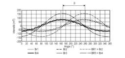
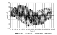
- Figures 6 and 7 respectively represent the combinations of the tangential and axial components of the field, obtained by combining the measurements provided by four probes arranged relatively to each other in a configuration according to the invention
- Figures 16a,16b,17a,17b,18a,18b illustrate the impact of an external magnetic field on the angular errors
- Figures 20 and 21 illustrate the result of the calculation of the angular position provided by a sensor according to the invention operating in a degraded mode with only a pair of probes;
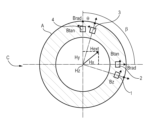
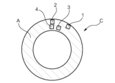
- the magnetic flux generated by a permanent disk-shaped permanent magnet A is collected at the periphery thereof by at least four sets of detection elements 1-4 (or magneto-sensitive) located radially or axially, without contact with the 'magnet.
- the permanent magnet can take a shape other than that of the disk of magnet A shown on the , it may in particular be in the shape of a ring or cylinder.
- Each set of detection elements measures, at the same point, at least two components of the magnetic induction, if necessary via flux collectors defining an air gap in which the detection elements 1-4 are placed.
- the magneto-sensitive elements may include, for example, Hall probes, magneto-resistive elements, eddy current elements, detection coils.
- each set of magneto-sensitive elements can be integrated into a housing to form a magnetic probe, capable of detecting two or three field components.
- probe in the remainder of this description, a set of magneto-sensitive elements capable of detecting, almost punctually, two or three field components. This designation, however, in no way limits the implementation of the principles of the invention, this implementation may include placing, in the same housing, several sets of magneto-sensitive elements to detect, at a plurality of points, the components of the field.
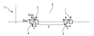
- the magnetic position sensor C of the therefore presents four probes 1-4, comprising on the one hand a first main probe 1 and a second main probe 2, and on the other hand a first secondary probe 3 and a second secondary probe 4.
- the first main probe 1 and the first secondary probe 2 form a first pair of probes 1,2 angularly phase shifted from one another by a first separation angle theta.
- the second main probe 3 and the second secondary probe 4 form a second pair of probes 3,4, also angularly out of phase with each other by the first separation angle theta.
- the first pair of probes 1.2 and the second pair of probes 3.4 are angularly out of phase with each other by a second separation angle beta.
- Permanent magnet A may be a multipolar magnet or an assembly of magnets or an equivalent machined magnet. This magnet can be made up of all or part of the rotor of an electric motor, a generator, an actuator, a reducer, a coupler, a gearbox, an oscillator. Alternatively, the permanent magnet can be made up of a set of current loops.
- the sensor also includes a processing circuit connected to probes 1-4 and configured to deliver a position signal depending on the absolute position (of the excursion) of the permanent magnet A.
- a magnetic position sensor C in accordance with the invention has a magnetization profile repeating the teaching of document FR3118804 cited in the introduction to the present application. This profile is complex and results in multi-periodic variations of the magnetization profile (or its orientation relative to an axis or reference point) depending on the relative trajectory of the measurement gap and the magnet .
- the permanent magnet A generates a magnetic field varying in a non-linear manner following the direction of movement, said variation presenting, according to the different field components, a shape corresponding to a combination of at least two different quasi-periodic contributions.
- This magnetization profile can thus present according to a first pattern, called "port”, of period p and comprising P measurement increments. It can also include a second pattern, called “carrier”, of period p*n (real n >0; constant or variable) comprising N increments.
- This double pattern makes it possible to combine coarse detection (global sensor output) and finer detection of the absolute position (local sensor output).
- a measurement increment is for example constituted by the measurement of a magnetic pole. Two poles of opposite polarity could thus constitute a period pattern given .
- This output signal includes a predetermined number of T measurement increments over the measurement interval.
- a second angular value (denoted beta), separating respectively the first main probe 1 and the first secondary probe 2 of the second main probe 3 and the second secondary probe 4, making it possible to generate, by combining a measurement of a field component produced by these probes 3,4, a second sinusoid of period representative of the carrier signal, in quadrature of the sinusoid obtained from the first pair of probes 1,2.
- This second beta angular value corresponds substantially to a quarter of a period of the carrier signal.
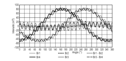
- the same approach can be used, this time combining the field components so as to highlight the signal carried, here by subtracting the components provided by the probes of the same pair two by two, as shown on the .
- the simultaneous calculation of the two angular values guarantees instantaneous and absolute knowledge of a precise angular (or linear) position, without the need for a minimum excursion to finalize a first calculation.
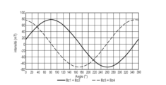
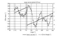
- the angle measured on a complete mechanical revolution makes it possible to obtain a value of the angular position at +/- 5° ( ).
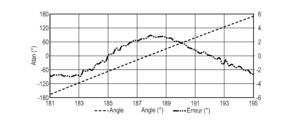
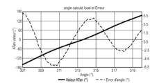
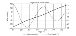
- the angle calculated over a period of the carried signal (a pair of increments) makes it possible to obtain a value of the local angular position at +/- 5° (electrical), as shown on the .
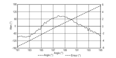
- the angle calculated over a period of the carried signal (a pair of increments) makes it possible to obtain a value of the local angular position at +/- 3° (electrical) as shown on the .
- Figures 17a, 17b and 18a, 18b allow us to compare the angular errors calculated in the two cases.
- a sensor C conforming to the present description may comprise a signal processing circuit for combining the components and determining an instantaneous global and local angular value. This circuit can also carry out the various compensations allowing these angular values to be corrected.
- this device can combine analog detection and digital detection of field components.
- the sensor C further comprises means for storing angular values and linearity coefficients used to compensate for the linearity of the sensor. These storage means are accessible to the signal processing circuit, which can use them to apply processing aimed at compensating for the linearity of the sensor.
- the senor further comprises means making it possible to determine, as a function of the overall angular position, the increment or the pair of increments facing each other. This increment or pair of increments is called “active”.
- Each active increment is (for example) associated with an order number or even with a global angular position (identified for example with the "zero-crossing" of one of the field components or a composition of components. This method allows to easily and precisely ensure that the increment read corresponds to the overall value calculated, without risk of error with a neighboring increment.
- Each increment may include magnetization anomalies, the exact angular value of each increment can be used to respect the true angular values read on the magnetic track.
- 157.30+183.4/(360/15.7) 165.29°.
- the mode of detection of the field components can be of the axial type or of the radial type, or a combination.
- the field component detection mode can be carried out on different faces of the magnetic target simultaneously.
- the senor further comprises self-calibration means, making it possible to adjust certain calculation values during the life of the sensor to maintain an optimum level of performance.
- the senor further comprises diagnostic means, making it possible to alert on a possible failure (probe, magneto-sensitive element, magnetic track, communication, calculation, temperature, external field, sensor travel, speed, etc.), and to engage a possibly degraded mode allowing the sensor to operate with reduced performance.
- diagnostic means making it possible to alert on a possible failure (probe, magneto-sensitive element, magnetic track, communication, calculation, temperature, external field, sensor travel, speed, etc.), and to engage a possibly degraded mode allowing the sensor to operate with reduced performance.
- This degraded mode notably allows detection using a minimum number of magneto-sensitive elements.
- the global position (right graph) is obtained with an Atan(Bz/Btan) calculation or with an Asin(Brad), in which Brad, Btan and Brz correspond respectively to the sum of the radial, tangential and axial field components provided by each of the two probes.
- the calculated linearity is +/-6° over a complete mechanical revolution.
- the local position is obtained with an Atan(Bz/Btan) calculation or with an Asin(Brad), in which Brad, Btan and Brz correspond respectively to the differences in the radial, tangential and axial field components provided by each of the two probes ( .b).
- the calculated linearity is +/-3° over a pair of increments, either +/-0.125° or one full mechanical revolution.
- the first pair and the second probe pair can in this case be separated by any second angular value (beta), for example chosen to be zero.
- a method for determining the precise angular position according to the calculated angular measurements will first include calculating the global position and the local position. Secondly, a compensated value of these angular positions can be defined. Finally, a detection diagnosis can be carried out in order to validate the measurement and, if necessary, engage a degraded detection mode. The rotation speed and direction values will be defined from the calculated angular values.
- a mathematical function (a polynomial for example) can be used to compensate for the angular value (or linear excursion) calculations.
- Each increment will be associated with all the coefficients required to define this function (6 coefficients for a polynomial of order 5) and a combination of functions.
- a trigonometric function (or its equivalent) can be used to compensate for the angular value (or linear excursion) calculations.
- Each increment will be associated with the set of coefficients required to define this function (for example: intensity, period, angular shift, offset), and a combination of functions.
- the senor may use only a very small number of magneto-sensitive elements capable of measuring one or more field components, or any combination, to meet space requirements or even price requirements. .
- This solution could also be considered for detections over very limited travels ( ⁇ 360° for a rotating sensor).
- the measuring device may include a plurality of probes each placed at a determined point making it possible to double or triple the operating mode.
- a single set of probes for example a set of 4 probes capable of measuring one or more field components.
- the use of 5.6, 7 or 8 probes can thus be considered, to create for example a completely redundant sensor for applications requiring a maximum level of integrity and operational safety (ASIL D type for the automobile) . This could also make it possible to enrich the combination of the different field components.
- the sensor C can take a linear configuration as shown .
- This linear configuration can be obtained by mentally unfolding a solution obtained for axial or radial angular detection.
- the field profile of the different field components being similar, the processing remains identical, taking care to properly position (linearly space) the sets of magneto-sensitive elements to obtain the first and second beta, theta angular values valid for the analysis differential.
- the sets of magneto-sensitive elements can be repositioned relative to the permanent magnet, so that the first angular value theta and/or the second angular value beta can be adjusted ( s).
- the sensor can find an application for measuring quantities additional to that of an angular or linear displacement in a complex system.
- This quantity can correspond to a force, a torque, an acceleration, a braking, a phase shift, an overall speed, a direction of movement, a distance, a number of revolutions, an inertia, an unbalance, a vibration, a noise , harmonic content, temperature, pressure, electric current, electric voltage, electric current, frequency, information coding.
Landscapes
- Physics & Mathematics (AREA)
- General Physics & Mathematics (AREA)
- Measurement Of Length, Angles, Or The Like Using Electric Or Magnetic Means (AREA)
- Transmission And Conversion Of Sensor Element Output (AREA)
Abstract
Description
- un aimant permanent générant un champ magnétique variant de façon non linéaire suivant la direction de déplacement, ladite variation comportant dans les différentes composantes de champ une combinaison d'au moins un premier signal quasi périodique, dit « signal porté » et d’au moins un deuxième signal quasi périodique, dit « signal porteur », le premier et le deuxième signal étant différents l’un de l’autre,
- au moins un premier couple de sondes comprenant une première sonde principale et une première sonde secondaire, le premier couple étant associé à l’aimant permanent et chaque sonde étant aptes à mesurer au moins deux composantes de champs en un même point ; et
- un circuit de traitement relié aux sondes et configuré pour exploiter certaines au moins des mesures fournies par les sondes et pour délivrer un signal de position représentatif de la position absolue de l’aimant permanent.
- le capteur de position magnétique comprend un deuxième couple de sondes comprenant une seconde sonde principale et une seconde sonde secondaire, le deuxième couple de sondes étant associé à l’aimant permanent et chaque sonde du deuxième couple de sondes étant aptes à mesurer au moins deux composantes de champs en un même point, les deux couples de sondes étant positionnés relativement entres eux de manière à obtenir une mise en quadrature des signaux obtenus par combinaison différentielle ;
- le circuit de traitement établi :
- la mesure de la position globale du capteur en combinant les composantes de champ selon la formule : Atan2 ((Br1+Bt3)+(Br2+Bt4) ; Gain*((Br3-Bt1)+(Br4-Bt2))) ou
- la mesure de la position locale du capteur en combinant les composantes de champ selon la formule : Atan2 ((Br3-Bt1)-(Br4-Bt2); Gain*(Bz1-Bz2)),
- le circuit de traitement établi la mesure de la position locale du capteur en combinant les composantes de champ selon la formule : Atan2 ((Bz3-Bt1)-(Bz4-Bt2) ; Gain*((Bz1+Bt3)-(Bz2+Bt4))), dans lequel Bri, Bti et Bzi représentent respectivement le champ radial, tangentiel et axial mesuré par une sonde d’indice i et dans lequel Gain est une grandeur choisie de façon à minimiser l'erreur angulaire calculée sur l'excursion du capteur ;
- le circuit de traitement établi la mesure de la position globale et/ou la mesure de position locale sur différentes faces de l’aimant permanent simultanément ;
- l’aimant permanent est un aimant multipolaire ou un assemblage d'aimants ou un aimant usiné équivalent.
- l’aimant permanent est constitué par un ensemble de boucles de courant ;
- l’aimant permanent est constitué par tout ou partie du rotor d'un moteur électrique, d'un générateur, d'un actionneur, d'un réducteur, d'un coupleur, d'une boite de vitesse, ou d'un oscillateur ;
- chaque sonde comprend une pluralité d’éléments magnéto-sensibles choisis dans la liste formée d’une sonde de Hall, d’un élément magnéto-résistif, d’un élément à courant de Foucault, d’une bobine de détection ;
- l’aimant permanent présente une forme de disque, de bague ou de cylindre, les sondes du au moins un couple de sondes étant disposées en périphérie de l’aimant ;
- les sondes du au moins un couple de sondes sont séparées d’une première valeur angulaire correspondant à une demi-période du signal porté ;
- les sondes du premier couple de sondes et les sondes du second couple de sondes sont respectivement séparées entre elles d’une seconde valeur angulaire sensiblement égale à un quart de période du signal porteur ;
- la première valeur angulaire et/ou la seconde valeur angulaire est ajustable ;
- le circuit de traitement est configuré pour exploiter un facteur de compensation angulaire pour corriger les valeurs angulaires calculées ;
- la correction des valeurs angulaires calculées se fonde sur des fonctions trigonométriques ;
- le circuit de traitement est configuré pour combiner une détection analogique et une détection digitale des composantes de champ.
- La première sonde secondaire 2 disposée le long d’un premier axe x mesure Br2+Hx le champ radial Br2 de l’aimant auquel s’ajoute la projection Hx selon le premier axe x d’un champ extérieur Hext. Similairement, la seconde sonde secondaire 4 disposée le long d’un second axe y, en quadrature avec l’axe x, mesure Bt4-Hx le champ tangentiel Bt4 de l’aimant 4 auquel se retranche la projection Hx selon le premier axe x du champ extérieur Hext. La somme de ces deux mesures (Br2+Hx)+(Bt4-Hx) est donc immune à la composante Hx selon le premier axe x d’un champ extérieur. La même observation peut être faite en choisissant l’autre paire de sondes en quadrature 1,3.
- La première sonde secondaire 2 disposée le long du premier axe x mesure Bt2+Hy le champ tangentiel Bt2 de l’aimant auquel s’ajoute la projection Hy selon le second axe y d’un champ extérieur Hext. Similairement, la seconde sonde secondaire 4 disposée le long du second axe y mesure Br4+Hy le champ radial Br4 de l’aimant 4 auquel s’ajoute également la projection Hy selon le second axe y du champ extérieur Hext. La différence de ces deux mesures (Bt2+Hy)-(Br4+Hy) est donc immune à cette composante Hy selon le second axe y du champ extérieur Hext. La même observation peut être faite en choisissant l’autre paire de sondes en quadrature 1,3.
- Enfin, la première sonde secondaire 2 disposée le long du premier axe x mesure Bz2+Hz le champ axial de l’aimant auquel s’ajoute la projection Hz selon un troisième axe z (formant un trièdre avec le premier et le second axe x,y) d’un champ extérieur Hext. Similairement, la seconde sonde secondaire 4 disposée le long du second axe y mesure Bz4+Hz le champ axial Bz4 de l’aimant 4 auquel s’ajoute également la projection Hz selon l’axe z du champ extérieur Hext. La différence de ces deux mesures (Bz2+Hz)-(Bz4+Hz) est donc immune à cette composante Hz selon le troisième axe z du champ extérieur Hext.
- Br1+Bt3 et Br2+Bt4, et leur addition ;
- Br3-Bt1 et Br4-Bt2, et leur addition ;
- Atan2 ((Br1+Bt3)+(Br2+Bt4) ; Gain*((Br3-Bt1)+(Br4-Bt2)))
- la valeur du Gain est ajustée de façon à minimiser l'erreur angulaire calculée sur l'excursion du capteur (ici 0.998)
- Br3-Bt1 et Br4-Bt2, et leur soustraction;
- Bz1-Bz2 ;
- Atan2 ((Br3-Bt1)-(Br4-Bt2); Gain*(Bz1-Bz2))
- la valeur du Gain est ajustée de façon à minimiser l'erreur angulaire calculée sur l'excursion du capteur (ici 0.933)
- Bz1+Bt3 et Bz2+Bt4, et leur soustraction ;
- Bz3-Bt1 et Bz4-Bt2, et leur soustraction ;
- atan2 ((Bz3-Bt1)-(Bz4-Bt2) ; Gain*((Bz1+Bt3)-(Bz2+Bt4)))
- la valeur du Gain est ajustée de façon à minimiser l'erreur angulaire calculée sur l'excursion du capteur (ici 0.995).
- un premier couple de sondes 1,2 déphasées de la première valeur angulaire thêta correspondant à une demi-période du signal porté. Ce premier couple de sondes 1,2 peut être exploité pour déterminer une position locale.
- un second couple de sondes 3,4 déphasées d’une valeur angulaire correspondant à une période du signal. Ce second couple de sondes 3,4 peut être exploité pour déterminer une position globale.
Claims (16)
- Capteur de position magnétique (C) sans contact, angulaire ou linéaire, comportant :
- un aimant permanent (A) générant un champ magnétique variant de façon non linéaire suivant la direction de déplacement, ladite variation comportant dans les différentes composantes de champ une combinaison d'au moins un premier signal quasi périodique, dit « signal porté » et d’au moins un deuxième signal quasi périodique, dit « signal porteur », le premier et le deuxième signal étant différents l’un de l’autre,
- au moins un premier couple de sondes (1,2 ;3,4) comprenant une première sonde principale (1 ;3) et une première sonde secondaire (2 ;4), le premier couple étant associé à l’aimant permanent (A) et chaque sonde étant aptes à mesurer au moins deux composantes de champs en un même point ; et
- un circuit de traitement relié aux sondes et configuré pour exploiter certaines au moins des mesures fournies par les sondes et pour délivrer un signal de position représentatif de la position absolue de l’aimant permanent (A),
- Capteur de position magnétique (C) selon la revendication précédente comprenant un deuxième couple de sondes (3,4) comprenant une seconde sonde principale (3) et une seconde sonde secondaire (4) séparées d’une valeur angulaire correspondant à une période du signal porté.
- Capteur de position magnétique (C) selon la revendication 1 comprenant un deuxième couple de sondes (3,4) comprenant une seconde sonde principale (3) et une seconde sonde secondaire (4), le deuxième couple de sondes (3,4) étant associé à l’aimant permanent (A) et chaque sonde du deuxième couple de sondes (3,4) étant aptes à mesurer au moins deux composantes de champs en un même point, les deux couples de sondes (1,2 ;3,4) étant positionnés relativement entres eux de manière à obtenir une mise en quadrature obtenus des signaux par combinaison différentielle.
- Capteur de position magnétique (C) sans contact selon la revendication précédente dans lequel les sondes du premier couple de sondes (1,2) et les sondes du second couple de sondes (3,4) sont respectivement séparées entre elles d’une seconde valeur angulaire (bêta) sensiblement égale à un quart de période du signal porteur.
- Capteur de position magnétique (C) sans contact selon la revendication précédente dans lequel la première valeur angulaire (thêta) et/ou la seconde valeur angulaire (bêta) est ajustable.
- Capteur de position magnétique (C) sans contact selon l’une des revendications 3 à 5, dans lequel le circuit de traitement établit :
- la mesure de la position globale du capteur en combinant les composantes de champ selon la formule : Atan2 ((Br1+Bt3)+(Br2+Bt4) ; Gain*((Br3-Bt1)+(Br4-Bt2))) ou
- la mesure de la position locale du capteur en combinant les composantes de champ selon la formule : Atan2 ((Br3-Bt1)-(Br4-Bt2); Gain*(Bz1-Bz2)),
- Capteur de position magnétique (C) sans contact selon l’une des revendications 3 à 6 dans lequel le circuit de traitement établi la mesure de la position locale du capteur en combinant les composantes de champ selon la formule : Atan2 ((Bz3-Bt1)-(Bz4-Bt2) ; Gain*((Bz1+Bt3)-(Bz2+Bt4))), dans lequel Bri, Bti et Bzi représentent respectivement le champ radial, tangentiel et axial mesuré par une sonde d’indice i et dans lequel Gain est une grandeur choisie de façon à minimiser l'erreur angulaire calculée sur l'excursion du capteur.
- Capteur de position magnétique (C) sans contact selon l’une des revendications précédentes, dans lequel l’aimant permanent (A) est un aimant multipolaire ou un assemblage d'aimants ou un aimant usiné équivalent.
- Capteur de position magnétique (C) sans contact selon l’une des revendications 1 à 7, dans lequel l’aimant permanent (A) est constitué par un ensemble de boucles de courant.
- Capteur de position magnétique (C) sans contact selon l’une des revendications précédentes, dans lequel l’aimant permanent (A) est constitué par tout ou partie du rotor d'un moteur électrique, d'un générateur, d'un actionneur, d'un réducteur, d'un coupleur, d'une boite de vitesse, ou d'un oscillateur.
- Capteur de position magnétique (C) sans contact selon l’une des revendications précédentes, dans lequel chaque sonde (1,2;3,4) comprend une pluralité d’éléments magnéto-sensibles choisis dans la liste formée d’une sonde de Hall, d’un élément magnéto-résistif, d’un élément à courant de Foucault, d’une bobine de détection.
- Capteur de position magnétique (C) sans contact selon l’une des revendications précédentes dans lequel l’aimant permanent (A) présente une forme de disque, de bague ou de cylindre, les sondes du au moins un couple de sondes (1,2 ;3,4) étant disposées en périphérie de l’aimant.
- Capteur de position magnétique (C) sans contact selon l'une des revendications précédentes dans lequel le circuit de traitement est configuré pour exploiter un facteur de compensation angulaire pour corriger les valeurs angulaires calculées.
- Capteur de position magnétique (C) sans contact selon la revendication précédente dans lequel la correction des valeurs angulaires calculées se fonde sur des fonctions trigonométriques.
- Capteur de position magnétique (C) sans contact selon l’une des deux revendications précédentes dans lequel le circuit de traitement est configuré pour combiner une détection analogique et une détection digitale des composantes de champ.
- Utilisation d’un capteur de position magnétique (C) sans contact selon l’une quelconque des revendications précédentes pour la mesure de valeurs additionnelles sur un système complexe, comprenant une force, un couple, une accélération, un freinage, un déphasage, une vitesse d’ensemble, une direction de déplacement, une distance, un nombre de tours, une inertie, un balourd, une vibration, un bruit, un contenu harmonique, une température, une pression, un courant électrique, une tension électrique, un courant électrique, une fréquence, un codage d’information.
Priority Applications (4)
| Application Number | Priority Date | Filing Date | Title |
|---|---|---|---|
| KR1020257020805A KR20250116056A (ko) | 2022-11-22 | 2023-09-26 | 고정밀 각도 또는 선형 비접촉 자기 위치 센서 |
| EP23776975.7A EP4623276A1 (fr) | 2022-11-22 | 2023-09-26 | Capteur de position magnétique sans contact angulaire ou linéaire de haute précision |
| CN202380080415.1A CN120225838A (zh) | 2022-11-22 | 2023-09-26 | 高精度角度或线性非接触式磁性位置传感器 |
| JP2025551050A JP2025536855A (ja) | 2022-11-22 | 2023-09-26 | 高精度の角度又は線形非接触磁気位置センサ |
Applications Claiming Priority (2)
| Application Number | Priority Date | Filing Date | Title |
|---|---|---|---|
| FR2212135A FR3142243B1 (fr) | 2022-11-22 | 2022-11-22 | Capteur de position magnétique sans contact angulaire ou linéaire de haute précision |
| FRFR2212135 | 2022-11-22 |
Publications (1)
| Publication Number | Publication Date |
|---|---|
| WO2024110102A1 true WO2024110102A1 (fr) | 2024-05-30 |
Family
ID=85018066
Family Applications (1)
| Application Number | Title | Priority Date | Filing Date |
|---|---|---|---|
| PCT/EP2023/076591 Ceased WO2024110102A1 (fr) | 2022-11-22 | 2023-09-26 | Capteur de position magnétique sans contact angulaire ou linéaire de haute précision |
Country Status (6)
| Country | Link |
|---|---|
| EP (1) | EP4623276A1 (fr) |
| JP (1) | JP2025536855A (fr) |
| KR (1) | KR20250116056A (fr) |
| CN (1) | CN120225838A (fr) |
| FR (1) | FR3142243B1 (fr) |
| WO (1) | WO2024110102A1 (fr) |
Citations (13)
| Publication number | Priority date | Publication date | Assignee | Title |
|---|---|---|---|---|
| EP0363512A1 (fr) * | 1988-10-13 | 1990-04-18 | Siemens Aktiengesellschaft | Dispositif sans-contact pour établir la vitesse d'une roue dentée |
| EP1083406A2 (fr) | 1999-09-09 | 2001-03-14 | Delphi Technologies, Inc. | Capteur de position rotative |
| US7030608B2 (en) | 2004-05-14 | 2006-04-18 | Denso Corporation | Rotational angle sensing device and assembling method thereof |
| EP1777501A1 (fr) * | 2005-10-24 | 2007-04-25 | Getrag Ford Transmissions GmbH | Agencement de capteurs de position destiné à la détermination de position sans contact à l aide d'éléments de capteur magnétiquement sensibles redondants |
| FR2893410A1 (fr) | 2005-11-15 | 2007-05-18 | Moving Magnet Tech Mmt | Capteur de position angulaire magnetique pour une course allant jusqu'a 360 |
| EP1989505A1 (fr) | 2006-03-02 | 2008-11-12 | Moving Magnet Technologies "M.M.T." | Capteur de position a direction d'aimantation variable et procede de realisation |
| FR2923903A1 (fr) | 2007-11-20 | 2009-05-22 | Moving Magnet Tech | Capteur de position magnetique angulaire ou lineaire presentant une insensibilite aux champs exterieurs |
| US7741839B2 (en) | 2005-10-20 | 2010-06-22 | Cts Corporation | Non-contacting position sensor using a rotating magnetic vector |
| FR2965347A1 (fr) | 2010-09-29 | 2012-03-30 | Moving Magnet Tech | Capteur de position ameliore |
| EP2711663A1 (fr) | 2012-09-25 | 2014-03-26 | MCB Industrie | Dispositif haute précision de mesure magnétique et/ou électromagnétique d'une position angulaire d'un point |
| EP3588011A1 (fr) * | 2018-06-26 | 2020-01-01 | Melexis Technologies SA | Système et procédé de capteur de position, solides contre les champs de perturbation |
| WO2020005160A1 (fr) * | 2018-06-28 | 2020-01-02 | Agency For Science, Technology And Research | Codeur magnétique |
| FR3118804A1 (fr) | 2021-01-14 | 2022-07-15 | Richard Arlot | Capteur de position sans contact comportant un aimant permanent. |
-
2022
- 2022-11-22 FR FR2212135A patent/FR3142243B1/fr active Active
-
2023
- 2023-09-26 CN CN202380080415.1A patent/CN120225838A/zh active Pending
- 2023-09-26 EP EP23776975.7A patent/EP4623276A1/fr active Pending
- 2023-09-26 WO PCT/EP2023/076591 patent/WO2024110102A1/fr not_active Ceased
- 2023-09-26 JP JP2025551050A patent/JP2025536855A/ja active Pending
- 2023-09-26 KR KR1020257020805A patent/KR20250116056A/ko active Pending
Patent Citations (14)
| Publication number | Priority date | Publication date | Assignee | Title |
|---|---|---|---|---|
| EP0363512A1 (fr) * | 1988-10-13 | 1990-04-18 | Siemens Aktiengesellschaft | Dispositif sans-contact pour établir la vitesse d'une roue dentée |
| EP1083406A2 (fr) | 1999-09-09 | 2001-03-14 | Delphi Technologies, Inc. | Capteur de position rotative |
| US7030608B2 (en) | 2004-05-14 | 2006-04-18 | Denso Corporation | Rotational angle sensing device and assembling method thereof |
| US7741839B2 (en) | 2005-10-20 | 2010-06-22 | Cts Corporation | Non-contacting position sensor using a rotating magnetic vector |
| EP1777501A1 (fr) * | 2005-10-24 | 2007-04-25 | Getrag Ford Transmissions GmbH | Agencement de capteurs de position destiné à la détermination de position sans contact à l aide d'éléments de capteur magnétiquement sensibles redondants |
| FR2893410A1 (fr) | 2005-11-15 | 2007-05-18 | Moving Magnet Tech Mmt | Capteur de position angulaire magnetique pour une course allant jusqu'a 360 |
| EP1989505A1 (fr) | 2006-03-02 | 2008-11-12 | Moving Magnet Technologies "M.M.T." | Capteur de position a direction d'aimantation variable et procede de realisation |
| FR2923903A1 (fr) | 2007-11-20 | 2009-05-22 | Moving Magnet Tech | Capteur de position magnetique angulaire ou lineaire presentant une insensibilite aux champs exterieurs |
| WO2009101270A2 (fr) | 2007-11-20 | 2009-08-20 | Moving Magnet Technologies (Mmt) | Capteur de position magnetique angulaire ou lineaire presentant une insensibilite aux champs exterieurs |
| FR2965347A1 (fr) | 2010-09-29 | 2012-03-30 | Moving Magnet Tech | Capteur de position ameliore |
| EP2711663A1 (fr) | 2012-09-25 | 2014-03-26 | MCB Industrie | Dispositif haute précision de mesure magnétique et/ou électromagnétique d'une position angulaire d'un point |
| EP3588011A1 (fr) * | 2018-06-26 | 2020-01-01 | Melexis Technologies SA | Système et procédé de capteur de position, solides contre les champs de perturbation |
| WO2020005160A1 (fr) * | 2018-06-28 | 2020-01-02 | Agency For Science, Technology And Research | Codeur magnétique |
| FR3118804A1 (fr) | 2021-01-14 | 2022-07-15 | Richard Arlot | Capteur de position sans contact comportant un aimant permanent. |
Also Published As
| Publication number | Publication date |
|---|---|
| CN120225838A (zh) | 2025-06-27 |
| EP4623276A1 (fr) | 2025-10-01 |
| JP2025536855A (ja) | 2025-11-07 |
| KR20250116056A (ko) | 2025-07-31 |
| FR3142243A1 (fr) | 2024-05-24 |
| FR3142243B1 (fr) | 2025-03-07 |
Similar Documents
| Publication | Publication Date | Title |
|---|---|---|
| EP2163851B1 (fr) | Système et procédé de mesure du mouvement axial d'une pièce mobile en rotation | |
| EP2163852B1 (fr) | Système et procédé de mesure du mouvement axial d'une pièce mobile en rotation | |
| JP5096442B2 (ja) | 回転角計測装置,モータシステム及び電動パワーステアリング・システム | |
| CN103403499B (zh) | 用于确定运动体的绝对位置的方法和装置 | |
| JP5913640B2 (ja) | 動く物体の絶対位置を冗長的に計測する装置及び方法 | |
| US9719771B2 (en) | Rotation angle sensor for absolute rotation angle determination even upon multiple revolutions | |
| US20140375312A1 (en) | Systems and Methods for Providing Signal Encoding Representative of a Signature Region in a Target | |
| US20220381800A1 (en) | Amr speed and direction sensor for use with magnetic targets | |
| EP3513149B1 (fr) | Système de détermination d'au moins un paramètre de rotation d'un organe tournant | |
| EP3540377B1 (fr) | Système de détermination d'au moins un paramètre de rotation d'un organe tournant | |
| WO2008071875A2 (fr) | Capteur de position lineaire ou rotatif a profil d'aimant variable | |
| EP3325922B1 (fr) | Capteur de mesure de la position absolue d'un mobile | |
| EP2163850B1 (fr) | Dispositif de codage magnétique | |
| EP4004512A1 (fr) | Détection de groupe motopropulseur simple à l'aide de capteurs à réluctance variable | |
| WO2024110102A1 (fr) | Capteur de position magnétique sans contact angulaire ou linéaire de haute précision | |
| EP4278154B1 (fr) | Capteur de position sans contact comportant un aimant permanent | |
| US12455176B2 (en) | Device and system for determining a position of a magnetic source, or an orientation of a uniform magnetic field | |
| Santos et al. | Foucault's currents based position sensor | |
| Bakos et al. | Design and analysis of a magnetic off-axis rotary position sensing device | |
| EP3708964A1 (fr) | Système de détermination d'au moins un paramètre de rotation d'un organe tournant | |
| FR3007845A1 (fr) | Capteur de detection d’un champ magnetique periodique emis par un codeur |
Legal Events
| Date | Code | Title | Description |
|---|---|---|---|
| 121 | Ep: the epo has been informed by wipo that ep was designated in this application |
Ref document number: 23776975 Country of ref document: EP Kind code of ref document: A1 |
|
| WWE | Wipo information: entry into national phase |
Ref document number: 202380080415.1 Country of ref document: CN |
|
| ENP | Entry into the national phase |
Ref document number: 2025551050 Country of ref document: JP Kind code of ref document: A |
|
| WWE | Wipo information: entry into national phase |
Ref document number: 2025551050 Country of ref document: JP |
|
| WWE | Wipo information: entry into national phase |
Ref document number: 1020257020805 Country of ref document: KR |
|
| WWE | Wipo information: entry into national phase |
Ref document number: 2023776975 Country of ref document: EP |
|
| NENP | Non-entry into the national phase |
Ref country code: DE |
|
| WWP | Wipo information: published in national office |
Ref document number: 202380080415.1 Country of ref document: CN |
|
| ENP | Entry into the national phase |
Ref document number: 2023776975 Country of ref document: EP Effective date: 20250623 |
|
| WWP | Wipo information: published in national office |
Ref document number: 1020257020805 Country of ref document: KR |
|
| WWP | Wipo information: published in national office |
Ref document number: 2023776975 Country of ref document: EP |