WO2024111338A1 - ジュール・トムソン冷凍機 - Google Patents
ジュール・トムソン冷凍機 Download PDFInfo
- Publication number
- WO2024111338A1 WO2024111338A1 PCT/JP2023/038529 JP2023038529W WO2024111338A1 WO 2024111338 A1 WO2024111338 A1 WO 2024111338A1 JP 2023038529 W JP2023038529 W JP 2023038529W WO 2024111338 A1 WO2024111338 A1 WO 2024111338A1
- Authority
- WO
- WIPO (PCT)
- Prior art keywords
- heat exchanger
- cooling
- cooling stage
- heat
- refrigerant
- Prior art date
- Legal status (The legal status is an assumption and is not a legal conclusion. Google has not performed a legal analysis and makes no representation as to the accuracy of the status listed.)
- Ceased
Links
Images


Classifications
-
- F—MECHANICAL ENGINEERING; LIGHTING; HEATING; WEAPONS; BLASTING
- F25—REFRIGERATION OR COOLING; COMBINED HEATING AND REFRIGERATION SYSTEMS; HEAT PUMP SYSTEMS; MANUFACTURE OR STORAGE OF ICE; LIQUEFACTION SOLIDIFICATION OF GASES
- F25B—REFRIGERATION MACHINES, PLANTS OR SYSTEMS; COMBINED HEATING AND REFRIGERATION SYSTEMS; HEAT PUMP SYSTEMS
- F25B9/00—Compression machines, plants or systems, in which the refrigerant is air or other gas of low boiling point
- F25B9/10—Compression machines, plants or systems, in which the refrigerant is air or other gas of low boiling point with several cooling stages
-
- F—MECHANICAL ENGINEERING; LIGHTING; HEATING; WEAPONS; BLASTING
- F25—REFRIGERATION OR COOLING; COMBINED HEATING AND REFRIGERATION SYSTEMS; HEAT PUMP SYSTEMS; MANUFACTURE OR STORAGE OF ICE; LIQUEFACTION SOLIDIFICATION OF GASES
- F25B—REFRIGERATION MACHINES, PLANTS OR SYSTEMS; COMBINED HEATING AND REFRIGERATION SYSTEMS; HEAT PUMP SYSTEMS
- F25B9/00—Compression machines, plants or systems, in which the refrigerant is air or other gas of low boiling point
- F25B9/02—Compression machines, plants or systems, in which the refrigerant is air or other gas of low boiling point using Joule-Thompson effect; using vortex effect
-
- F—MECHANICAL ENGINEERING; LIGHTING; HEATING; WEAPONS; BLASTING
- F25—REFRIGERATION OR COOLING; COMBINED HEATING AND REFRIGERATION SYSTEMS; HEAT PUMP SYSTEMS; MANUFACTURE OR STORAGE OF ICE; LIQUEFACTION SOLIDIFICATION OF GASES
- F25B—REFRIGERATION MACHINES, PLANTS OR SYSTEMS; COMBINED HEATING AND REFRIGERATION SYSTEMS; HEAT PUMP SYSTEMS
- F25B9/00—Compression machines, plants or systems, in which the refrigerant is air or other gas of low boiling point
- F25B9/14—Compression machines, plants or systems, in which the refrigerant is air or other gas of low boiling point characterised by the cycle used, e.g. Stirling cycle
-
- F—MECHANICAL ENGINEERING; LIGHTING; HEATING; WEAPONS; BLASTING
- F25—REFRIGERATION OR COOLING; COMBINED HEATING AND REFRIGERATION SYSTEMS; HEAT PUMP SYSTEMS; MANUFACTURE OR STORAGE OF ICE; LIQUEFACTION SOLIDIFICATION OF GASES
- F25B—REFRIGERATION MACHINES, PLANTS OR SYSTEMS; COMBINED HEATING AND REFRIGERATION SYSTEMS; HEAT PUMP SYSTEMS
- F25B2309/00—Gas cycle refrigeration machines
- F25B2309/02—Gas cycle refrigeration machines using the Joule-Thompson effect
- F25B2309/022—Gas cycle refrigeration machines using the Joule-Thompson effect characterised by the expansion element
Definitions
- the present invention relates to a Joule-Thomson (JT) refrigerator.
- JT Joule-Thomson
- JT refrigerator that includes a JT valve that enables cooling of refrigerant gas using JT expansion, and a pre-cooling refrigerator, such as a Gifford-McMahon (GM) refrigerator, that pre-cools the refrigerant gas supplied to the JT valve.
- GM Gifford-McMahon
- a so-called cool-down is performed to cool the JT refrigerator from the ambient temperature (for example, room temperature of around 300 K) to the desired cryogenic temperature.
- the refrigerant gas supplied to the JT valve is cooled from the ambient temperature to a temperature below the inversion temperature by the cool-down. Since the cool-down is merely a preparation for the JT refrigerator to cool the desired object to a cryogenic temperature, it is desirable for the time required for the cool-down to be as short as possible.
- One exemplary objective of one embodiment of the present invention is to reduce the cool-down time of a JT refrigerator.
- a JT refrigerator includes a pre-cooling refrigerator with a pre-cooling stage, a refrigerant circuit including a heat exchanger and a refrigerant piping extending from the heat exchanger and cooled by the pre-cooling stage, and a heat conduction path provided separately from the refrigerant piping and connecting the pre-cooling stage to the heat exchanger so as to enable conductive cooling of the heat exchanger by the pre-cooling stage.
- the present invention makes it possible to shorten the cool-down time of a JT refrigerator.
- 1 is a diagram illustrating a schematic diagram of a cryogenic cooling device according to an embodiment
- 1A and 1B are schematic diagrams illustrating exemplary configurations of heat conduction paths according to an embodiment
- 11A and 11B are diagrams each showing a schematic diagram of a modified example of a heat conduction path according to an embodiment.
- FIG. 1 is a schematic diagram of a cryogenic cooling device 10 according to an embodiment.
- the cryogenic cooling device 10 includes a vacuum vessel 12, a radiation shield 14, and a JT refrigerator 18 for cooling an object 16 to be cooled.
- the vacuum vessel 12 may be, for example, a cryostat, and is configured to provide an extremely low temperature vacuum environment therein.
- the vacuum vessel 12 is formed of a metallic material, such as stainless steel, or other suitable high strength material, to withstand ambient pressure (e.g., atmospheric pressure).
- a radiation shield 14 Disposed within the vacuum vessel 12 are a radiation shield 14, a low temperature section of a JT refrigerator 18, and an object to be cooled 16.
- the radiation shield 14 is arranged within the vacuum vessel 12 to surround the low-temperature section of the JT refrigerator 18 and the object to be cooled 16, and prevents radiant heat from entering the vacuum vessel 12 into the JT refrigerator 18 and the object to be cooled 16.
- the radiation shield 14 is formed of a highly thermally conductive metal material such as copper (e.g., pure copper).
- An insulating material such as a multi-layer insulating material may be arranged between the vacuum vessel 12 and the radiation shield 14.
- the object to be cooled 16 may be, for example, a superconducting device such as a superconducting coil, or a measuring device that operates better at cryogenic temperatures, or other equipment used at cryogenic temperatures.
- the object to be cooled 16 may be a cryogenic fluid such as liquid helium, and the JT refrigerator 18 may be used to recondense the vaporized cryogenic fluid.
- the JT refrigerator 18 includes a pre-cooling refrigerator 20 and a refrigerant circuit 40 including a JT valve 30 and a final heat exchanger 32.
- the refrigerant flowing through the refrigerant circuit 40 is pre-cooled by the pre-cooling refrigerator 20, further cooled by JT expansion in the JT valve 30, and supplied to the final heat exchanger 32.
- the object to be cooled 16 is cooled by heat exchange with the final heat exchanger 32.
- the cooled refrigerant is recovered from the final heat exchanger 32, pressurized by a compressor described below, pre-cooled again by the pre-cooling refrigerator 20, and supplied to the JT valve 30. In this way, the refrigerant circulates through the refrigerant circuit 40.
- the JT refrigerator 18 can cool the final heat exchanger 32 to a temperature range of, for example, about 4K or less (for example, 1K to 4K), and can therefore cool the object to be cooled 16 to that temperature range.
- the pre-cooling refrigerator 20 is, as an example, a two-stage GM refrigerator.
- the pre-cooling refrigerator 20 includes a first compressor 21 and an expander 22, also called a cold head.
- the expander 22 includes a drive unit 23, a first cylinder 24, a first pre-cooling stage 25, a second cylinder 26, and a second pre-cooling stage 27.
- the first compressor 21 is disposed in the ambient environment (e.g., room temperature and atmospheric pressure environment), i.e., outside the vacuum vessel 12.
- the expander 22 is installed in the vacuum vessel 12 such that the drive unit 23 is disposed outside the vacuum vessel 12, and the cylinder and the pre-cooling stage are disposed inside the vacuum vessel 12.
- the first cylinder 24 connects the first pre-cooling stage 25 to the drive unit 23, so that the first pre-cooling stage 25 is structurally supported by the drive unit 23.
- the second cylinder 26 connects the second pre-cooling stage 27 to the first pre-cooling stage 25, so that the second pre-cooling stage 27 is structurally supported by the first pre-cooling stage 25.
- the first cylinder 24 and the second cylinder 26 extend coaxially, and the drive unit 23, the first cylinder 24, the first pre-cooling stage 25, the second cylinder 26, and the second pre-cooling stage 27 are aligned in a straight line in this order.
- the first pre-cooling stage 25 and the second pre-cooling stage 27 are formed of a highly thermally conductive metal material such as copper (e.g., pure copper), and the first cylinder 24 and the second cylinder 26 are formed of another metal material, such as stainless steel.
- a highly thermally conductive metal material such as copper (e.g., pure copper)
- the first cylinder 24 and the second cylinder 26 are formed of another metal material, such as stainless steel.
- a first displacer and a second displacer are arranged reciprocally inside the first cylinder 24 and the second cylinder 26, respectively.
- a first regenerator and a second regenerator (not shown) are respectively incorporated in the first displacer and the second displacer.
- the drive unit 23 also has a drive mechanism (not shown) such as a motor for reciprocating the first displacer and the second displacer.
- the drive mechanism includes a flow path switching mechanism that switches the flow path of the refrigerant gas so as to periodically repeat the supply and discharge of the refrigerant gas to the inside of the expander 22.
- the refrigerant gas of the pre-cooling refrigerator 20 is typically helium gas, but other suitable gases may be used.
- the first compressor 21 is configured to recover refrigerant gas from the expander 22, pressurize the recovered refrigerant gas, and supply the refrigerant gas to the expander 22 again.
- the circulation of the refrigerant gas between the first compressor 21 and the expander 22 is performed with a combination of appropriate pressure fluctuations and volume fluctuations of the refrigerant gas within the expander 22, thereby forming a thermodynamic cycle (e.g., a GM cycle) that generates cold, and the expander 22 can provide cryogenic cooling.
- a thermodynamic cycle e.g., a GM cycle
- the first pre-cooling stage 25 is cooled to a first cooling temperature
- the second pre-cooling stage 27 is cooled to a second cooling temperature that is lower than the first cooling temperature.
- the first cooling temperature may be selected, for example, from a temperature range of 50 K or more and 150 K or less.
- the second cooling temperature may be selected, for example, from a temperature range of 10 K or more and 25 K or less.
- the radiation shield 14 is in physical contact with and thermally coupled to the first pre-cooling stage 25, or is thermally coupled to the first pre-cooling stage 25 via a heat transfer member. Therefore, the radiation shield 14 is cooled to the first cooling temperature by the first pre-cooling stage 25.
- the refrigerant circuit 40 includes, in addition to the JT valve 30 and the final heat exchanger 32, a second compressor 41, a heat exchanger group 42, and a refrigerant supply line 44 and a refrigerant recovery line 46 that connect these components.
- the refrigerant gas circulating through the refrigerant circuit 40 is typically helium gas, but other appropriate gases may be used. Note that the refrigerant circuit 40 is not limited to the specific configuration described here, and various typical configurations can be appropriately adopted.
- the second compressor 41 is configured to boost the refrigerant gas recovered from the refrigerant recovery line 46 and send it to the refrigerant supply line 44.
- the second compressor 41 serves as a refrigerant source that circulates the refrigerant in the refrigerant circuit 40.
- the second compressor 41 is disposed outside the vacuum vessel 12.
- the heat exchanger group 42 is disposed between the second compressor 41 and the final heat exchanger 32.
- the heat exchanger group 42 is made up of a series of counterflow heat exchangers (42a-42c), and in this embodiment has a three-stage configuration of a first heat exchanger 42a, a second heat exchanger 42b, and a third heat exchanger 42c.
- the first heat exchanger 42a is disposed between the vacuum vessel 12 and the radiation shield 14, i.e., in the space inside the vacuum vessel 12 and outside the radiation shield 14.
- the second heat exchanger 42b, the third heat exchanger 42c, and the final heat exchanger 32 are disposed inside the radiation shield 14.
- the first heat exchanger 42a cools the high-temperature (e.g., room temperature, e.g., about 300 K) refrigerant gas that flows into the vacuum vessel 12 from outside the vacuum vessel 12.
- the second heat exchanger 42b further cools the refrigerant cooled by the first heat exchanger 42a and the first pre-cooling stage 25.
- the third heat exchanger 42c further cools the refrigerant cooled by the second heat exchanger 42b and the second pre-cooling stage 27.
- the refrigerant supply line 44 connects the discharge side of the second compressor 41 to the refrigerant inlet of the final heat exchanger 32
- the refrigerant return line 46 connects the refrigerant outlet of the final heat exchanger 32 to the suction side of the second compressor 41.
- the refrigerant supply line 44 has high-pressure side flow paths for the first heat exchanger 42a, the second heat exchanger 42b, and the third heat exchanger 42c
- the refrigerant return line 46 has low-pressure side flow paths for the first heat exchanger 42a, the second heat exchanger 42b, and the third heat exchanger 42c.
- the refrigerant flowing through the high-pressure side flow path can be cooled by heat exchange between the high-pressure side flow path and the low-pressure side flow path in each heat exchanger.
- the high-pressure side flow path and the low-pressure side flow path can also be called the high-temperature side flow path and the low-temperature side flow path, respectively.
- the refrigerant supply line 44 includes a first refrigerant pipe 44a and a second refrigerant pipe 44b.
- These refrigerant pipes are formed of a highly thermally conductive metal material such as copper (e.g., pure copper).
- the first refrigerant pipe 44a extends from the first heat exchanger 42a through the first pre-cooling stage 25 to the second heat exchanger 42b.
- the first refrigerant pipe 44a connects the high-pressure side flow path of the first heat exchanger 42a to the high-pressure side flow path of the second heat exchanger 42b.
- the first refrigerant pipe 44a is thermally coupled to the first pre-cooling stage 25, and the refrigerant flowing through the first refrigerant pipe 44a is cooled by the first pre-cooling stage 25.
- the first refrigerant pipe 44a may be fixed to the first pre-cooling stage 25 in a state where it is wrapped around the outer circumferential surface of the first pre-cooling stage 25.
- the second refrigerant pipe 44b extends from the second heat exchanger 42b through the second pre-cooling stage 27 to the third heat exchanger 42c.
- the second refrigerant pipe 44b connects the high-pressure side flow path of the second heat exchanger 42b to the high-pressure side flow path of the third heat exchanger 42c.
- the second refrigerant pipe 44b is thermally coupled to the second pre-cooling stage 27, and the refrigerant flowing through the second refrigerant pipe 44b is cooled by the second pre-cooling stage 27.
- the second refrigerant pipe 44b may be fixed to the second pre-cooling stage 27 in a state where it is wrapped around the outer circumferential surface of the second pre-cooling stage 27.
- the JT valve 30 is disposed in the refrigerant supply line 44 between the last heat exchanger of the heat exchanger group 42 (the third heat exchanger 42c in this example) and the final heat exchanger 32.
- the high-pressure side flow path of the third heat exchanger 42c is connected to the refrigerant inlet of the final heat exchanger 32 via the JT valve 30.
- the JT valve 30 is a fixed orifice.
- the JT valve 30 may be a variable orifice whose opening is adjustable.
- the refrigerant flows through the refrigerant circuit 40 as follows.
- the high-pressure refrigerant compressed by the second compressor 41 is first supplied to the high-pressure side flow path of the first heat exchanger 42a.
- the high-pressure refrigerant flowing through the high-pressure side flow path of the first heat exchanger 42a is cooled by heat exchange with the returning low-pressure refrigerant flowing through the low-pressure side flow path of the first heat exchanger 42a.
- the high-pressure refrigerant cooled in the first heat exchanger 42a flows into the first refrigerant piping 44a.
- the high-pressure refrigerant flowing through the first refrigerant pipe 44a is cooled by the first pre-cooling stage 25 of the pre-cooling refrigerator 20 and sent to the high-pressure side flow path of the second heat exchanger 42b.
- the high-pressure refrigerant flowing through the high-pressure side flow path of the second heat exchanger 42b is cooled by heat exchange with the returning low-pressure refrigerant flowing through the low-pressure side flow path of the second heat exchanger 42b.
- the high-pressure refrigerant cooled by the second heat exchanger 42b flows into the second refrigerant pipe 44b.
- the high-pressure refrigerant flowing through the second refrigerant pipe 44b is cooled by the second pre-cooling stage 27 of the pre-cooling refrigerator 20 and sent to the high-pressure side flow path of the third heat exchanger 42c.
- the high-pressure refrigerant flowing through the high-pressure side flow path of the third heat exchanger 42c is cooled by heat exchange with the returning low-pressure refrigerant flowing through the low-pressure side flow path of the third heat exchanger 42c. In this way, the high-pressure refrigerant is cooled to a temperature at which the JT effect is expected (i.e. a temperature below the inversion temperature) and sent to the JT valve 30.
- this cooled high-pressure refrigerant passes through the JT valve 30, it becomes a mist-like low-pressure refrigerant in a gas-liquid mixed state due to the Joule-Thomson effect, generating cooling capacity in the temperature range of the liquid refrigerant.
- the mist-like low-pressure refrigerant is sent to the final heat exchanger 32.
- the final heat exchanger 32 can be cooled to the liquid helium temperature range.
- the final heat exchanger 32 can cool the object 16 to that temperature by exchanging heat with the object 16 to be cooled.
- the mist-like low-pressure refrigerant evaporates and vaporizes again.
- the refrigerant that has not been liquefied and the refrigerant that has evaporated are returned to the low-pressure side flow path of the third heat exchanger 42c.
- the low-pressure refrigerant flows through the refrigerant recovery line 46 in the order of the third heat exchanger 42c, the second heat exchanger 42b, and the first heat exchanger 42a.
- the low-pressure refrigerant is heated while cooling the high-pressure refrigerant in each heat exchanger (42c, 42b, 42a).
- the low-pressure refrigerant that has returned to room temperature in this way leaves the vacuum container 12 and is recovered in the second compressor 41, where it is compressed again.
- the cryogenic cooling device 10 can cool the object 16 to a desired temperature that is lower than the second cooling temperature of the pre-cooling refrigerator 20, for example, about 4 K or less (for example, 1 K to 4 K).
- the JT refrigerator 18 When the JT refrigerator 18 is started, the JT refrigerator 18 is cooled from the ambient temperature (for example, room temperature of about 300 K) to the desired cryogenic temperature (for example, the lowest temperature that can be reached, below 4 K). This initial cooling is also called cool down.
- the refrigerant gas supplied to the JT valve 30 is cooled from the ambient temperature to a temperature below the inversion temperature by cool down. Since cool down is merely a preparation for cooling the object 16 to a cryogenic temperature by the JT refrigerator 18, it is desirable that the time required for cool down be as short as possible.
- the JT valve 30 is designed to achieve an optimal JT flow rate at extremely low temperatures. Therefore, the refrigerant gas flow rate that can pass through the JT valve 30 at the beginning of the cool-down period when the refrigerant gas temperature is high can be significantly small. This can significantly increase the time it takes to cool down.
- the cool-down time can be shortened by opening the JT valve 30 wider than the optimal opening at extremely low temperatures at the start of cool-down to ensure a large flow rate, and then reducing the opening of the JT valve 30 as cooling progresses.
- this measure is time-consuming. For example, a service technician may be required to adjust the opening of the JT valve 30 appropriately.
- the JT valve 30 is a fixed orifice, this measure cannot be adopted (as a result, it may take more than twice as long to cool the JT refrigerator 18 to the minimum temperature (e.g., about 4 K) compared to the case of a variable orifice).
- the pre-cooling chiller and the heat exchanger of the JT refrigerant circuit are generally arranged so that they are not thermally connected to each other in order to prevent heat from entering the JT refrigerant circuit from the pre-cooling chiller during normal operation.
- the pre-cooling stage of the pre-cooling chiller is supported by the surrounding structure using insulating materials such as fiber-reinforced plastic, and there is effectively no thermal conduction path from the pre-cooling stage to the heat exchanger.
- the JT refrigerator 18 includes a heat conduction path 48 that connects at least one pre-cooling stage and at least one heat exchanger of the pre-cooling refrigerator 20 to enable the pre-cooling refrigerator 20 to conduction-cool at least one heat exchanger of the heat exchanger group 42.
- the heat conduction path 48 may connect the second pre-cooling stage 27 to at least one of the second heat exchanger 42b and the third heat exchanger 42c to enable the second pre-cooling stage 27 to conduction-cool at least one of the second heat exchanger 42b and the third heat exchanger 42c.
- the JT refrigerator 18 may include a first heat conduction path 48a connecting the second pre-cooling stage 27 to the second heat exchanger 42b to enable conductive cooling of the second heat exchanger 42b by the second pre-cooling stage 27. Additionally or alternatively, the JT refrigerator 18 may include a second heat conduction path 48b connecting the second pre-cooling stage 27 to the third heat exchanger 42c to enable conductive cooling of the third heat exchanger 42c by the second pre-cooling stage 27.
- the heat conduction path 48 is installed so that the temperature difference between both ends of the heat conduction path 48 is as small as possible during normal operation of the JT refrigerator 18.
- the heat conduction path 48 may be installed so that the temperature difference between both ends of the heat conduction path 48 is, for example, less than 5 K or less than 3 K during normal operation of the JT refrigerator 18.
- the first heat transfer path 48a may be connected to the cold side of the second heat exchanger 42b.
- the cold side of the second heat exchanger 42b and the second pre-cooling stage 27 of the pre-cooling refrigerator 20 are expected to be at similar temperatures (e.g., about 12 K) during normal operation of the JT refrigerator 18.
- the high temperature side of the second heat exchanger 42b is assumed to be at approximately the same temperature as the first pre-cooling stage 25 of the pre-cooling refrigerator 20. If the first heat conduction path 48a were to connect the high temperature side of the second heat exchanger 42b to the second pre-cooling stage 27 of the pre-cooling refrigerator 20, during normal operation of the JT refrigerator 18, a temperature difference equivalent to the temperature difference between the first pre-cooling stage 25 and the second pre-cooling stage 27 would occur between both ends of the first heat conduction path 48a, increasing the heat load on the second pre-cooling stage 27 and potentially having an undesirable effect on the refrigeration performance of the JT refrigerator 18.
- the second heat transfer path 48b may be connected to the low temperature side of the third heat exchanger 42c.
- the second heat transfer path 48b may be connected to the high temperature side of the third heat exchanger 42c.
- the refrigerant pipes that make up the refrigerant circuit 40 structurally connect the pre-cooling stage and the heat exchanger, but because their cross-sectional area perpendicular to the pipe axis is quite small, they are unable to achieve sufficient thermal conduction to enable a reduction in the cool-down time.
- the heat transfer path 48 is therefore provided separately from the refrigerant piping that constitutes the refrigerant circuit 40. That is, the first heat transfer path 48a is provided separately from the second refrigerant piping 44b, and thermally couples the second pre-cooling stage 27 and the second heat exchanger 42b to each other. The second heat transfer path 48b is provided separately from the second refrigerant piping 44b, and thermally couples the second pre-cooling stage 27 and the third heat exchanger 42c to each other.
- the thermal conduction path 48 is formed of one or more thermally conductive members.
- thermally conductive members are formed of, for example, a metal material with high thermal conductivity, such as copper (e.g., pure copper or a copper alloy) or aluminum (e.g., pure aluminum or an aluminum alloy), or other highly thermally conductive materials.
- the thermally conductive member may be formed of, for example, a material with a higher thermal conductivity than stainless steel (e.g., SUS304).
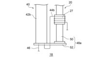
- FIG. 2 is a schematic diagram illustrating an exemplary configuration of a heat conduction path according to an embodiment.
- the first heat conduction path 48a has a stage extension component 50 and a heat conduction plate 52 as an example of a heat conduction member.
- the stage extension part 50 is a tubular (e.g., cylindrical) heat-conducting member made of a highly heat-conducting material (e.g., pure copper), and is thermally coupled to the second pre-cooling stage 27 at one end and to the heat-conducting plate 52 at the other end.
- a flange formed at one end of the stage extension part 50 may be fixed to the second pre-cooling stage 27 by a fastening member such as a bolt, and a flange formed at the other end of the stage extension part 50 may be fixed to the heat-conducting plate 52.
- the heat conducting plate 52 is a flat heat conducting member made of a highly heat conducting material (e.g., an aluminum alloy), and the stage extension part 50 and the low temperature end of the second heat exchanger 42b are thermally coupled by the heat conducting plate 52.
- the stage extension part 50 and the second heat exchanger 42b may be disposed on the same side of the heat conducting plate 52 and fixed to the same surface of the heat conducting plate 52.
- the second heat exchanger 42b may have a typical configuration with a cylindrical housing.
- the second heat exchanger 42b may include a mandrel arranged coaxially inside the housing, and piping wound around the outer periphery of the mandrel and arranged in a cylindrical cavity between the mandrel and the housing.
- the piping may be used as the high-pressure side flow path of the second heat exchanger 42b, and the cylindrical cavity may be used as the low-pressure side flow path of the second heat exchanger 42b.
- the second refrigerant piping 44b and the refrigerant recovery line 46 penetrate the low-temperature end plate of the housing of the second heat exchanger 42b.
- the second refrigerant piping 44b is connected to the high-pressure side flow path of the second heat exchanger 42b, and the refrigerant recovery line 46 is connected to the low-pressure side flow path of the second heat exchanger 42b.
- the second refrigerant piping 44b is wound around and attached to the second pre-cooling stage 27 so as to enable heat exchange with the second pre-cooling stage 27.
- the third heat exchanger 42c may also be thermally coupled to the second pre-cooling stage 27 via the heat conduction plate 52 and the stage extension part 50 in a similar manner.
- the third heat exchanger 42c may also have a cylindrical outer shape like the second heat exchanger 42b, and its low temperature end may be fixed to the heat conduction plate 52.
- the third heat exchanger 42c may be arranged in parallel with the second heat exchanger 42b, in front of or behind the second heat exchanger 42b with respect to the plane of the paper in FIG. 2.
- the second heat exchanger 42b and the third heat exchanger 42c are connected to the second pre-cooling stage 27 of the pre-cooling refrigerator 20 by the heat conduction path 48.
- conductive cooling via the heat conduction path 48 can be used to promote cooling of the heat exchanger group 42 of the JT refrigerator 18.
- the cool-down time of the JT refrigerator 18 can be shortened.
- the existing design which does not have a thermal conduction path 48, requires approximately 24 hours to cool down, whereas the embodiment in which the thermal conduction path 48 is provided makes it possible to complete the cool down in approximately 12 hours.
- FIG. 3 is a schematic diagram showing a modified example of the heat transfer path according to the embodiment.
- the third heat exchanger 42c may be thermally coupled to the second pre-cooling stage 27 by a second heat transfer path 48b.
- the second heat transfer path 48b may include a heat resistance element 60 in addition to the heat transfer members (e.g., the stage extension part 50 and the heat transfer plate 52).
- the second heat transfer path 48b may connect the second pre-cooling stage 27 to the third heat exchanger 42c via the heat resistance element 60.
- the thermal resistance element 60 may be a spacer made of a metal material or other material having a lower thermal conductivity than the thermal conduction member, and the third heat exchanger 42c may be fixed to the thermal conduction plate 52 so as to sandwich the thermal resistance element 60 between its low temperature end and the thermal conduction plate 52.
- the thermal resistance element 60 may be made of stainless steel (e.g., SUS304).
- a refrigerant supply line 44 and a refrigerant return line 46 are connected to the low-temperature side end plate of the housing of the third heat exchanger 42c.
- the refrigerant supply line 44 is connected to the high-pressure side flow path of the third heat exchanger 42c, and the refrigerant return line 46 is connected to the low-pressure side flow path of the third heat exchanger 42c.
- the refrigerant supply line 44 is connected to the JT valve 30.
- a certain degree of temperature difference may occur between the low-temperature end of the third heat exchanger 42c and the second pre-cooling stage 27.
- the second pre-cooling stage 27 may be cooled to about 12 K as described above.
- the second pre-cooling stage 27 serves as a heat source for the third heat exchanger 42c, and the heat entering the third heat exchanger 42c from the second pre-cooling stage 27 via the second heat conduction path 48b may reduce the refrigeration performance of the JT refrigerator 18.
- the second heat conduction path 48b is provided with a thermal resistance element 60, it is possible to limit the heat input to the third heat exchanger 42c via the second heat conduction path 48b that may occur during normal operation of the JT refrigerator 18. Therefore, the above-mentioned problems can be reduced or prevented.
- a thermal resistance element 60 may be provided in the first thermal conduction path 48a.
- the first thermal conduction path 48a may connect the second pre-cooling stage 27 to the second heat exchanger 42b via the thermal resistance element 60.
- the pre-cooling refrigerator 20 is not limited to a GM refrigerator.
- the pre-cooling refrigerator 20 may be another type of cryogenic refrigerator, such as a pulse tube refrigerator or a Stirling refrigerator.
- the heat exchanger group 42 has the first to third heat exchangers, but the heat exchanger group 42 may have other multi-stage configurations.
- the JT chiller 18 may have an additional heat exchanger (i.e., a fourth heat exchanger) between the third heat exchanger 42c and the final heat exchanger 32.
- the above-mentioned JT valve 30 may be disposed in the refrigerant supply line 44 between the last heat exchanger (i.e., the fourth heat exchanger) of the heat exchanger group 42 and the final heat exchanger 32.
- the JT refrigerator 18 may employ a two-stage JT expansion method, in which a first JT valve is disposed in the refrigerant supply line 44 between the third heat exchanger 42c and the fourth heat exchanger, and a second JT valve is disposed in the refrigerant supply line 44 between the fourth heat exchanger and the final heat exchanger 32.
- the JT refrigerator 18 may include a third heat conduction path connecting the second pre-cooling stage 27 to the fourth heat exchanger to enable conductive cooling of the fourth heat exchanger by the second pre-cooling stage 27.
- the third heat conduction path may also be a stage extension part 50 and a heat conduction plate 52, similar to the first heat conduction path 48a and the second heat conduction path 48b. That is, the fourth heat exchanger may be thermally coupled to the second pre-cooling stage 27 via the heat conduction plate 52 and the stage extension part 50.
- the present invention can be used in the field of Joule-Thomson refrigerators.
- cryogenic cooling device 18 JT refrigerator, 20 pre-cooling refrigerator, 25 first pre-cooling stage, 27 second pre-cooling stage, 30 JT valve, 32 final heat exchanger, 40 refrigerant circuit, 42 heat exchanger group, 42a first heat exchanger, 42b second heat exchanger, 42c third heat exchanger, 44a first refrigerant piping, 44b second refrigerant piping, 48 heat transfer path, 48a first heat transfer path, 48b second heat transfer path, 50 stage extension part, 52 heat transfer plate, 60 heat resistance element.
Landscapes
- Engineering & Computer Science (AREA)
- Physics & Mathematics (AREA)
- Mechanical Engineering (AREA)
- Thermal Sciences (AREA)
- General Engineering & Computer Science (AREA)
- Compressors, Vaccum Pumps And Other Relevant Systems (AREA)
- Containers, Films, And Cooling For Superconductive Devices (AREA)
Abstract
Description
Claims (10)
- 予冷ステージを備える予冷冷凍機と、
熱交換器と、前記熱交換器から延び、前記予冷ステージによって冷却される冷媒配管と、を備える冷媒回路と、
前記冷媒配管とは別個に設けられ、前記予冷ステージによる前記熱交換器の伝導冷却を可能にするように前記予冷ステージを前記熱交換器に接続する熱伝導経路と、を備えることを特徴とするジュール・トムソン冷凍機。 - 前記予冷冷凍機は、前記予冷ステージから延在するシリンダを備え、
前記熱伝導経路は、
前記予冷ステージに熱的に結合され、前記予冷ステージから前記シリンダとは反対側に延在する第1熱伝導部材と、
前記熱交換器に前記第1熱伝導部材を熱的に結合する第2熱伝導部材と、を備えることを特徴とする請求項1に記載のジュール・トムソン冷凍機。 - 前記予冷冷凍機は、第1予冷ステージと、前記第1予冷ステージよりも低温に冷却される第2予冷ステージと、を備え、
前記冷媒回路は、第1熱交換器と、前記第1熱交換器によって冷却された冷媒をさらに冷却する第2熱交換器と、前記第2熱交換器によって冷却された冷媒をさらに冷却する第3熱交換器と、を備え、前記冷媒配管は、前記第2熱交換器から前記第2予冷ステージを経由して前記第3熱交換器へと延び、
前記熱伝導経路は、前記第2予冷ステージによる前記第2熱交換器と前記第3熱交換器の少なくとも一方の伝導冷却を可能にするように、前記第2予冷ステージを前記第2熱交換器と前記第3熱交換器の前記少なくとも一方に接続することを特徴とする請求項1に記載のジュール・トムソン冷凍機。 - 前記熱伝導経路は、前記第2予冷ステージによる前記第2熱交換器の伝導冷却を可能にするように、前記第2予冷ステージを前記第2熱交換器に接続することを特徴とする請求項3に記載のジュール・トムソン冷凍機。
- 前記予冷冷凍機は、前記第2予冷ステージを前記第1予冷ステージに接続するシリンダを備え、
前記熱伝導経路は、
前記予冷ステージに熱的に結合され、前記予冷ステージから前記シリンダとは反対側に延在するステージ延長部品と、
前記第2熱交換器と前記第3熱交換器の前記少なくとも一方に前記ステージ延長部品を熱的に結合する熱伝導プレートと、を備えることを特徴とする請求項3に記載のジュール・トムソン冷凍機。 - 前記第2熱交換器と前記第3熱交換器の前記少なくとも一方と前記ステージ延長部品は、前記熱伝導プレートに対して同じ側に配置されていることを特徴とする請求項5に記載のジュール・トムソン冷凍機。
- 前記熱伝導経路は、熱抵抗要素を含むことを特徴とする請求項1に記載のジュール・トムソン冷凍機。
- 前記熱伝導経路は、前記熱交換器と第2熱伝導部材との間に熱抵抗要素を備え、
前記熱抵抗要素の熱伝導率は、前記第2熱伝導部材の熱伝導率よりも小さいことを特徴とする請求項2に記載のジュール・トムソン冷凍機。 - 前記熱伝導経路は、熱抵抗要素を介して前記第2予冷ステージを前記第3熱交換器に接続することを特徴とする請求項3または4に記載のジュール・トムソン冷凍機。
- 前記熱伝導経路は、前記第3熱交換器と前記熱伝導プレートとの間に熱抵抗要素を備え、
前記熱抵抗要素の熱伝導率は、前記熱伝導プレートの熱伝導率よりも小さいことを特徴とする請求項5または6に記載のジュール・トムソン冷凍機。
Priority Applications (4)
| Application Number | Priority Date | Filing Date | Title |
|---|---|---|---|
| CN202380078967.9A CN120202385A (zh) | 2022-11-24 | 2023-10-25 | 焦耳-汤姆逊制冷机 |
| EP23894350.0A EP4624829A4 (en) | 2022-11-24 | 2023-10-25 | JOULE-THOMSON REFRIGERATOR |
| JP2024560030A JPWO2024111338A1 (ja) | 2022-11-24 | 2023-10-25 | |
| US19/211,274 US20250277607A1 (en) | 2022-11-24 | 2025-05-18 | Joule-thomson cryocooler |
Applications Claiming Priority (2)
| Application Number | Priority Date | Filing Date | Title |
|---|---|---|---|
| JP2022-187736 | 2022-11-24 | ||
| JP2022187736 | 2022-11-24 |
Related Child Applications (1)
| Application Number | Title | Priority Date | Filing Date |
|---|---|---|---|
| US19/211,274 Continuation US20250277607A1 (en) | 2022-11-24 | 2025-05-18 | Joule-thomson cryocooler |
Publications (1)
| Publication Number | Publication Date |
|---|---|
| WO2024111338A1 true WO2024111338A1 (ja) | 2024-05-30 |
Family
ID=91195447
Family Applications (1)
| Application Number | Title | Priority Date | Filing Date |
|---|---|---|---|
| PCT/JP2023/038529 Ceased WO2024111338A1 (ja) | 2022-11-24 | 2023-10-25 | ジュール・トムソン冷凍機 |
Country Status (5)
| Country | Link |
|---|---|
| US (1) | US20250277607A1 (ja) |
| EP (1) | EP4624829A4 (ja) |
| JP (1) | JPWO2024111338A1 (ja) |
| CN (1) | CN120202385A (ja) |
| WO (1) | WO2024111338A1 (ja) |
Cited By (1)
| Publication number | Priority date | Publication date | Assignee | Title |
|---|---|---|---|---|
| FR3164272A1 (fr) * | 2024-07-03 | 2026-01-09 | L'air Liquide, Societe Anonyme Pour L'etude Et L'exploitation Des Procedes Georges Claude | Installation et procédé de réfrigération cryogénique |
Families Citing this family (1)
| Publication number | Priority date | Publication date | Assignee | Title |
|---|---|---|---|---|
| WO2024186633A2 (en) * | 2023-03-03 | 2024-09-12 | Maybell Quantum Industries, Inc. | Cryogenic system including integrated cryocooler and dilution refrigerator |
Citations (5)
| Publication number | Priority date | Publication date | Assignee | Title |
|---|---|---|---|---|
| US4265220A (en) * | 1979-04-23 | 1981-05-05 | Mcalister Roy E | Multiple fluid medium system and improved hot water supply tank assembly utilized therein |
| JPH0571817A (ja) * | 1991-09-12 | 1993-03-23 | Nec Corp | 冷却装置 |
| JP2003214719A (ja) | 2002-01-23 | 2003-07-30 | Sumitomo Heavy Ind Ltd | 極低温冷却方法及び装置 |
| JP2006125772A (ja) * | 2004-10-29 | 2006-05-18 | Chubu Electric Power Co Inc | 極低温冷凍機の運転制御装置 |
| JP2020003098A (ja) * | 2018-06-26 | 2020-01-09 | 株式会社アルバック | パルス管冷凍機 |
Family Cites Families (4)
| Publication number | Priority date | Publication date | Assignee | Title |
|---|---|---|---|---|
| JP4431793B2 (ja) * | 2006-07-07 | 2010-03-17 | 国立大学法人九州大学 | クライオスタット |
| JP2008241215A (ja) * | 2007-03-28 | 2008-10-09 | Kyushu Univ | 蓄冷型極低温冷凍機 |
| JP6445752B2 (ja) * | 2013-06-28 | 2018-12-26 | 株式会社東芝 | 超電導磁石装置 |
| JP7319462B2 (ja) * | 2020-04-23 | 2023-08-01 | 住友重機械工業株式会社 | 超電導磁石装置、および超電導磁石装置の冷却方法 |
-
2023
- 2023-10-25 EP EP23894350.0A patent/EP4624829A4/en active Pending
- 2023-10-25 CN CN202380078967.9A patent/CN120202385A/zh active Pending
- 2023-10-25 JP JP2024560030A patent/JPWO2024111338A1/ja active Pending
- 2023-10-25 WO PCT/JP2023/038529 patent/WO2024111338A1/ja not_active Ceased
-
2025
- 2025-05-18 US US19/211,274 patent/US20250277607A1/en active Pending
Patent Citations (5)
| Publication number | Priority date | Publication date | Assignee | Title |
|---|---|---|---|---|
| US4265220A (en) * | 1979-04-23 | 1981-05-05 | Mcalister Roy E | Multiple fluid medium system and improved hot water supply tank assembly utilized therein |
| JPH0571817A (ja) * | 1991-09-12 | 1993-03-23 | Nec Corp | 冷却装置 |
| JP2003214719A (ja) | 2002-01-23 | 2003-07-30 | Sumitomo Heavy Ind Ltd | 極低温冷却方法及び装置 |
| JP2006125772A (ja) * | 2004-10-29 | 2006-05-18 | Chubu Electric Power Co Inc | 極低温冷凍機の運転制御装置 |
| JP2020003098A (ja) * | 2018-06-26 | 2020-01-09 | 株式会社アルバック | パルス管冷凍機 |
Non-Patent Citations (1)
| Title |
|---|
| See also references of EP4624829A1 |
Cited By (1)
| Publication number | Priority date | Publication date | Assignee | Title |
|---|---|---|---|---|
| FR3164272A1 (fr) * | 2024-07-03 | 2026-01-09 | L'air Liquide, Societe Anonyme Pour L'etude Et L'exploitation Des Procedes Georges Claude | Installation et procédé de réfrigération cryogénique |
Also Published As
| Publication number | Publication date |
|---|---|
| EP4624829A1 (en) | 2025-10-01 |
| JPWO2024111338A1 (ja) | 2024-05-30 |
| EP4624829A4 (en) | 2026-03-11 |
| CN120202385A (zh) | 2025-06-24 |
| US20250277607A1 (en) | 2025-09-04 |
Similar Documents
| Publication | Publication Date | Title |
|---|---|---|
| US5317878A (en) | Cryogenic cooling apparatus | |
| EP3477225B1 (en) | Cryogenic system | |
| Matsubara et al. | Novel configuration of three-stage pulse tube refrigerator for temperatures below 4 K | |
| US20250277607A1 (en) | Joule-thomson cryocooler | |
| CN114739031B (zh) | 一种稀释制冷系统 | |
| JP2011512509A (ja) | 冷媒蒸気圧縮システム | |
| US20230107973A1 (en) | Dilution refrigeration device and method | |
| CN103047788B (zh) | 低温线性压缩机驱动的j-t节流制冷循环系统 | |
| JPH08222429A (ja) | 極低温装置 | |
| US11649989B2 (en) | Heat station for cooling a circulating cryogen | |
| JP4595121B2 (ja) | 機械式冷凍機とジュール・トムソン膨張を用いた極低温冷凍装置 | |
| JPH10246524A (ja) | 冷凍装置 | |
| Uhlig | 3He/4He dilution refrigerator with high cooling capacity and direct pulse tube pre-cooling | |
| US20250277604A1 (en) | Joule-thomson cryocooler | |
| JPH09113052A (ja) | 冷凍装置 | |
| JP5886163B2 (ja) | 極低温冷凍機 | |
| CN111936802B (zh) | 冷却循环制冷剂的热站 | |
| Kruthiventi et al. | Performance of J–T refrigerators operating with mixtures and coiled wire-finned heat exchangers: SSH Kruthiventi, G. Venkatarathnam | |
| JP2007078310A (ja) | 極低温冷却装置 | |
| US20240377107A1 (en) | Cryogenic cooling device | |
| US20250003643A1 (en) | Cryogenic pumping system and innovative integration for sub-kelvin cryogenics below 1.5k | |
| Radebaugh | Introduction to Part F: Refrigeration Methods | |
| Britcliffe | Two-watt, 4-Kelvin closed cycle refrigerator performance | |
| WO2022153713A1 (ja) | パルス管冷凍機および超伝導磁石装置 | |
| Britcliffe | A closed-cycle refrigerator for cooling maser amplifiers below 4 Kelvin |
Legal Events
| Date | Code | Title | Description |
|---|---|---|---|
| 121 | Ep: the epo has been informed by wipo that ep was designated in this application |
Ref document number: 23894350 Country of ref document: EP Kind code of ref document: A1 |
|
| WWE | Wipo information: entry into national phase |
Ref document number: 2024560030 Country of ref document: JP |
|
| WWE | Wipo information: entry into national phase |
Ref document number: 202380078967.9 Country of ref document: CN |
|
| WWE | Wipo information: entry into national phase |
Ref document number: 2023894350 Country of ref document: EP |
|
| WWP | Wipo information: published in national office |
Ref document number: 202380078967.9 Country of ref document: CN |
|
| NENP | Non-entry into the national phase |
Ref country code: DE |
|
| ENP | Entry into the national phase |
Ref document number: 2023894350 Country of ref document: EP Effective date: 20250624 |
|
| WWP | Wipo information: published in national office |
Ref document number: 2023894350 Country of ref document: EP |