WO2024111641A1 - 方向性電磁鋼板及びその製造方法 - Google Patents
方向性電磁鋼板及びその製造方法 Download PDFInfo
- Publication number
- WO2024111641A1 WO2024111641A1 PCT/JP2023/042045 JP2023042045W WO2024111641A1 WO 2024111641 A1 WO2024111641 A1 WO 2024111641A1 JP 2023042045 W JP2023042045 W JP 2023042045W WO 2024111641 A1 WO2024111641 A1 WO 2024111641A1
- Authority
- WO
- WIPO (PCT)
- Prior art keywords
- groove
- steel sheet
- grain
- oriented electrical
- electrical steel
- Prior art date
- Legal status (The legal status is an assumption and is not a legal conclusion. Google has not performed a legal analysis and makes no representation as to the accuracy of the status listed.)
- Ceased
Links
Images

Classifications
-
- H—ELECTRICITY
- H01—ELECTRIC ELEMENTS
- H01F—MAGNETS; INDUCTANCES; TRANSFORMERS; SELECTION OF MATERIALS FOR THEIR MAGNETIC PROPERTIES
- H01F27/00—Details of transformers or inductances, in general
- H01F27/24—Magnetic cores
- H01F27/245—Magnetic cores made from sheets, e.g. grain-oriented
-
- C—CHEMISTRY; METALLURGY
- C21—METALLURGY OF IRON
- C21D—MODIFYING THE PHYSICAL STRUCTURE OF FERROUS METALS; GENERAL DEVICES FOR HEAT TREATMENT OF FERROUS OR NON-FERROUS METALS OR ALLOYS; MAKING METAL MALLEABLE, e.g. BY DECARBURISATION OR TEMPERING
- C21D9/00—Heat treatment, e.g. annealing, hardening, quenching or tempering, adapted for particular articles; Furnaces therefor
- C21D9/46—Heat treatment, e.g. annealing, hardening, quenching or tempering, adapted for particular articles; Furnaces therefor for sheet metals
-
- B—PERFORMING OPERATIONS; TRANSPORTING
- B23—MACHINE TOOLS; METAL-WORKING NOT OTHERWISE PROVIDED FOR
- B23K—SOLDERING OR UNSOLDERING; WELDING; CLADDING OR PLATING BY SOLDERING OR WELDING; CUTTING BY APPLYING HEAT LOCALLY, e.g. FLAME CUTTING; WORKING BY LASER BEAM
- B23K26/00—Working by laser beam, e.g. welding, cutting or boring
- B23K26/36—Removing material
- B23K26/362—Laser etching
- B23K26/364—Laser etching for making a groove or trench, e.g. for scribing a break initiation groove
-
- B—PERFORMING OPERATIONS; TRANSPORTING
- B24—GRINDING; POLISHING
- B24B—MACHINES, DEVICES, OR PROCESSES FOR GRINDING OR POLISHING; DRESSING OR CONDITIONING OF ABRADING SURFACES; FEEDING OF GRINDING, POLISHING, OR LAPPING AGENTS
- B24B29/00—Machines or devices for polishing surfaces on work by means of tools made of soft or flexible material with or without the application of solid or liquid polishing agents
- B24B29/005—Machines or devices for polishing surfaces on work by means of tools made of soft or flexible material with or without the application of solid or liquid polishing agents using brushes
-
- C—CHEMISTRY; METALLURGY
- C21—METALLURGY OF IRON
- C21D—MODIFYING THE PHYSICAL STRUCTURE OF FERROUS METALS; GENERAL DEVICES FOR HEAT TREATMENT OF FERROUS OR NON-FERROUS METALS OR ALLOYS; MAKING METAL MALLEABLE, e.g. BY DECARBURISATION OR TEMPERING
- C21D6/00—Heat treatment of ferrous alloys
- C21D6/008—Heat treatment of ferrous alloys containing Si
-
- C—CHEMISTRY; METALLURGY
- C21—METALLURGY OF IRON
- C21D—MODIFYING THE PHYSICAL STRUCTURE OF FERROUS METALS; GENERAL DEVICES FOR HEAT TREATMENT OF FERROUS OR NON-FERROUS METALS OR ALLOYS; MAKING METAL MALLEABLE, e.g. BY DECARBURISATION OR TEMPERING
- C21D7/00—Modifying the physical properties of iron or steel by deformation
- C21D7/02—Modifying the physical properties of iron or steel by deformation by cold working
- C21D7/04—Modifying the physical properties of iron or steel by deformation by cold working of the surface
-
- C—CHEMISTRY; METALLURGY
- C21—METALLURGY OF IRON
- C21D—MODIFYING THE PHYSICAL STRUCTURE OF FERROUS METALS; GENERAL DEVICES FOR HEAT TREATMENT OF FERROUS OR NON-FERROUS METALS OR ALLOYS; MAKING METAL MALLEABLE, e.g. BY DECARBURISATION OR TEMPERING
- C21D8/00—Modifying the physical properties of ferrous metals or ferrous alloys by deformation combined with, or followed by, heat treatment
- C21D8/12—Modifying the physical properties of ferrous metals or ferrous alloys by deformation combined with, or followed by, heat treatment during manufacturing of articles with special electromagnetic properties
- C21D8/1277—Modifying the physical properties of ferrous metals or ferrous alloys by deformation combined with, or followed by, heat treatment during manufacturing of articles with special electromagnetic properties involving a particular surface treatment
-
- C—CHEMISTRY; METALLURGY
- C21—METALLURGY OF IRON
- C21D—MODIFYING THE PHYSICAL STRUCTURE OF FERROUS METALS; GENERAL DEVICES FOR HEAT TREATMENT OF FERROUS OR NON-FERROUS METALS OR ALLOYS; MAKING METAL MALLEABLE, e.g. BY DECARBURISATION OR TEMPERING
- C21D8/00—Modifying the physical properties of ferrous metals or ferrous alloys by deformation combined with, or followed by, heat treatment
- C21D8/12—Modifying the physical properties of ferrous metals or ferrous alloys by deformation combined with, or followed by, heat treatment during manufacturing of articles with special electromagnetic properties
- C21D8/1294—Modifying the physical properties of ferrous metals or ferrous alloys by deformation combined with, or followed by, heat treatment during manufacturing of articles with special electromagnetic properties involving a localised treatment
-
- H—ELECTRICITY
- H01—ELECTRIC ELEMENTS
- H01F—MAGNETS; INDUCTANCES; TRANSFORMERS; SELECTION OF MATERIALS FOR THEIR MAGNETIC PROPERTIES
- H01F1/00—Magnets or magnetic bodies characterised by the magnetic materials therefor; Selection of materials for their magnetic properties
- H01F1/01—Magnets or magnetic bodies characterised by the magnetic materials therefor; Selection of materials for their magnetic properties of inorganic materials
- H01F1/03—Magnets or magnetic bodies characterised by the magnetic materials therefor; Selection of materials for their magnetic properties of inorganic materials characterised by their coercivity
- H01F1/12—Magnets or magnetic bodies characterised by the magnetic materials therefor; Selection of materials for their magnetic properties of inorganic materials characterised by their coercivity of soft-magnetic materials
- H01F1/14—Magnets or magnetic bodies characterised by the magnetic materials therefor; Selection of materials for their magnetic properties of inorganic materials characterised by their coercivity of soft-magnetic materials metals or alloys
- H01F1/147—Alloys characterised by their composition
-
- H—ELECTRICITY
- H01—ELECTRIC ELEMENTS
- H01F—MAGNETS; INDUCTANCES; TRANSFORMERS; SELECTION OF MATERIALS FOR THEIR MAGNETIC PROPERTIES
- H01F1/00—Magnets or magnetic bodies characterised by the magnetic materials therefor; Selection of materials for their magnetic properties
- H01F1/01—Magnets or magnetic bodies characterised by the magnetic materials therefor; Selection of materials for their magnetic properties of inorganic materials
- H01F1/03—Magnets or magnetic bodies characterised by the magnetic materials therefor; Selection of materials for their magnetic properties of inorganic materials characterised by their coercivity
- H01F1/12—Magnets or magnetic bodies characterised by the magnetic materials therefor; Selection of materials for their magnetic properties of inorganic materials characterised by their coercivity of soft-magnetic materials
- H01F1/14—Magnets or magnetic bodies characterised by the magnetic materials therefor; Selection of materials for their magnetic properties of inorganic materials characterised by their coercivity of soft-magnetic materials metals or alloys
- H01F1/16—Magnets or magnetic bodies characterised by the magnetic materials therefor; Selection of materials for their magnetic properties of inorganic materials characterised by their coercivity of soft-magnetic materials metals or alloys in the form of sheets
- H01F1/18—Magnets or magnetic bodies characterised by the magnetic materials therefor; Selection of materials for their magnetic properties of inorganic materials characterised by their coercivity of soft-magnetic materials metals or alloys in the form of sheets with insulating coating
-
- H—ELECTRICITY
- H01—ELECTRIC ELEMENTS
- H01F—MAGNETS; INDUCTANCES; TRANSFORMERS; SELECTION OF MATERIALS FOR THEIR MAGNETIC PROPERTIES
- H01F41/00—Apparatus or processes specially adapted for manufacturing or assembling magnets, inductances or transformers; Apparatus or processes specially adapted for manufacturing materials characterised by their magnetic properties
- H01F41/02—Apparatus or processes specially adapted for manufacturing or assembling magnets, inductances or transformers; Apparatus or processes specially adapted for manufacturing materials characterised by their magnetic properties for manufacturing cores, coils, or magnets
- H01F41/0206—Manufacturing of magnetic cores by mechanical means
- H01F41/0233—Manufacturing of magnetic circuits made from sheets
-
- C—CHEMISTRY; METALLURGY
- C21—METALLURGY OF IRON
- C21D—MODIFYING THE PHYSICAL STRUCTURE OF FERROUS METALS; GENERAL DEVICES FOR HEAT TREATMENT OF FERROUS OR NON-FERROUS METALS OR ALLOYS; MAKING METAL MALLEABLE, e.g. BY DECARBURISATION OR TEMPERING
- C21D2201/00—Treatment for obtaining particular effects
- C21D2201/05—Grain orientation
-
- C—CHEMISTRY; METALLURGY
- C22—METALLURGY; FERROUS OR NON-FERROUS ALLOYS; TREATMENT OF ALLOYS OR NON-FERROUS METALS
- C22C—ALLOYS
- C22C38/00—Ferrous alloys, e.g. steel alloys
- C22C38/004—Very low carbon steels, i.e. having a carbon content of less than 0,01%
-
- C—CHEMISTRY; METALLURGY
- C22—METALLURGY; FERROUS OR NON-FERROUS ALLOYS; TREATMENT OF ALLOYS OR NON-FERROUS METALS
- C22C—ALLOYS
- C22C38/00—Ferrous alloys, e.g. steel alloys
- C22C38/02—Ferrous alloys, e.g. steel alloys containing silicon
Definitions
- the present invention relates to a grain-oriented electrical steel sheet and a manufacturing method thereof.
- This application claims priority based on Japanese Patent Application No. 2022-186164, filed on November 22, 2022, the contents of which are incorporated herein by reference.
- Grain-oriented electrical steel sheets are soft magnetic materials and are mainly used as iron core materials for transformers. For this reason, grain-oriented electrical steel sheets are required to have magnetic properties such as high magnetization characteristics and low iron loss.
- Iron loss is the power loss consumed as thermal energy when an iron core is excited by an AC magnetic field, and from the viewpoint of energy saving, it is required that the iron loss be as low as possible.
- the level of iron loss is affected by magnetic susceptibility, sheet thickness, coating tension, amount of impurities, electrical resistivity, crystal grain size, magnetic domain width, etc.
- One method proposed for reducing iron loss is laser irradiation, which is said to reduce eddy current loss, which is a part of iron loss, by introducing distortion into the surface through laser irradiation and dividing the 180° magnetic domain width.
- the grain-oriented electrical steel sheet is bent and shaped, which requires stress relief annealing. Therefore, in this method, the strain introduced into the grain-oriented electrical steel sheet is released by stress relief annealing, and the effect of controlling the magnetic domains by laser irradiation cannot be obtained. For this reason, it has been proposed to form grooves on the surface of the steel sheet to subdivide the 180° magnetic domain width in the same manner as by introducing strain, thereby reducing eddy current loss.
- Patent Document 2 discloses a method for improving the iron loss characteristics of grain-oriented electrical steel sheet to which strain relief annealing can be applied, in which a laser beam is controlled and irradiated to form recesses having a rolling direction width of 0.5 mm or less and a depth of 10 ⁇ m or more.
- a laser beam is controlled and irradiated to form recesses having a rolling direction width of 0.5 mm or less and a depth of 10 ⁇ m or more.
- the molten material generated by the laser irradiation solidifies at the edges of the grooves, forming protrusions.
- These protrusions are usually composed of fine crystal grains with random crystal orientations other than the Goss orientation.
- protrusions reduces the magnetic flux density of the steel sheet and increases the hysteresis loss, which is a part of the iron loss, resulting in inferior characteristics.
- the above-mentioned protrusions can be removed to some extent by performing brushing or the like after laser irradiation. However, even if brushing or the like is performed, it is performed so as not to reduce the plate thickness, so it is difficult to completely remove the protrusions.
- Patent Document 2 does not take such protrusions into consideration.
- Patent Document 3 discloses a grain-oriented electrical steel sheet in which grooves are formed on the surface and magnetic domain refinement is performed, in which the scattered alloy layer in the groove is eroded by a Goss texture, and when the thickness of the scattered alloy layer at the bottom of the groove is defined as TB and the thickness of the scattered alloy layer at a point half the distance between either end of the groove and the bottom of the groove is defined as TL, the TB/TL ratio is 0.2 to 0.8.
- Patent Document 3 mentions the inside of the groove, it does not mention anything about the crystal orientation of the protrusions formed on the edges of the groove.
- Patent document 4 also describes a steel plate having a surface on which grooves are formed whose extension direction intersects with the rolling direction and whose depth direction is parallel to the plate thickness direction, and on both sides of the groove on the surface of the steel plate there is a molten solidification material that is parallel to the groove, and when a height distribution of height data measured at regular intervals on the steel plate surface within a specific area including the groove is determined as a virtual plane, the spatial volume of a recess recessed from the virtual plane is determined as V1, and the volume of a protrusion protruding from the virtual plane is determined as V2, the value of V2/V1 is 0.
- the grain-oriented electrical steel sheet is disclosed in which the specific region has a ratio of more than 10 and less than 0.80, a plurality of protrusions are formed, and among the plurality of protrusions, the width of the protrusion closest to the groove is greater than the width of the other protrusions, and when the region having the highest average height in the extension direction in the height distribution is viewed in a longitudinal cross section of the groove including the extension direction and the sheet thickness direction, the average roughness Ra of the roughness curve forming the surface of the region is 0.30 to 2.00 ⁇ m, and the average length RSm of the roughness curve elements forming the surface of the region is 10 to 150 ⁇ m.
- Patent Document 4 the crystal orientation of the protrusions in the region in the height distribution where the average height in the extension direction is the highest is specified, but the crystal orientation of the protrusions in other regions is not specified. Controlling the crystal orientation of any protrusion is important for reducing iron loss, but Patent Document 4 does not fully consider the crystal orientation of the protrusions and iron loss reduction.
- the 180° magnetic domain width is subdivided by forming grooves approximately parallel to the width direction of the steel sheet, and eddy current loss, which is part of the iron loss, is reduced accordingly.
- the grooves are formed by laser irradiation, protrusions are formed due to the solidification of the molten material generated by the laser irradiation at the edge of the groove. Since these protrusions are usually composed of fine crystal grains with random crystal orientations other than the Goss orientation, the presence of protrusions reduces the magnetic flux density of the steel sheet and increases the hysteresis loss, which is part of the iron loss, resulting in inferior characteristics.
- the protrusions are removed by brushing or the like after laser irradiation, but it is difficult to completely remove the protrusions because the brushing is performed so as not to reduce the sheet thickness. Furthermore, if there are protrusions on the edges of the grooves, there is a concern that the adhesion of the coating may deteriorate. However, up until now, sufficient consideration has not been given to the adhesion of the coating when there are protrusions.
- an object of the present invention is to provide a grain-oriented electrical steel sheet in which magnetic domain refinement is performed by forming grooves, in which the reduction in magnetic flux density caused by protrusions and the associated increase in hysteresis loss are suppressed, thereby achieving low iron loss, and a manufacturing method thereof.
- Another preferred object of the present invention is to provide a grain-oriented electrical steel sheet that can provide sufficient coating adhesion even when protrusions are present.
- the present inventors have conducted a study on suppressing an increase in hysteresis loss due to protrusions. As a result, they found that the increase in hysteresis loss can be suppressed by controlling the crystal orientation of the protrusions formed on the groove edges so that the proportion of the Goss orientation is high.
- the crystal orientation of the protrusions at the groove edge they found that by forming grooves on the surface of a steel plate by laser irradiation and then grinding the surface of the steel plate under specified conditions, the proportion of the protrusions whose crystal orientation is the Goss orientation during subsequent annealing can be increased. They also found that by controlling the grinding conditions to bring the surface roughness into a predetermined range, the coating adhesion can be further improved.
- a grain-oriented electrical steel sheet has a steel sheet on its surface having a plurality of grooves formed thereon that extend in a direction intersecting the rolling direction and have a depth in the sheet thickness direction, and in a cross section parallel to the rolling direction and the sheet thickness direction, the distance from an entrance of a groove to an entrance of the opposite groove is defined as a groove width, a region from the entrance of the groove of the steel sheet in the rolling direction in a direction opposite to the center of the groove is defined as a groove edge that is equal to the width of the groove, and a surface in a region from the entrance of the groove in the rolling direction in a direction opposite to the center of the groove is defined as a reference plane, the groove edge has a width of 1 ⁇ m or more and a protrusion height from the reference plane of 1 ⁇ m or more, and the area ratio of Goss-oriented grains in the protrusions is 10% or more.
- the arithmetic mean roughness Ra of the surface of the groove edge portion of the steel sheet along the extension direction of the groove, including the apex of the protrusion may be more than 2.0 ⁇ m and not more than 5.0 ⁇ m.
- a forsterite coating may be formed on the surface of the steel sheet.
- an insulating coating may be formed on a surface of the forsterite coating.
- an insulating coating may be formed on the surface of the steel sheet.
- a manufacturing method of grain-oriented electrical steel sheet according to another aspect of the present invention is the manufacturing method of grain-oriented electrical steel sheet according to [1], comprising: a groove forming step of forming grooves on the surface by irradiating the steel sheet with a laser; and a grinding step of grinding the surface of the steel sheet using a brush roll to which abrasive grains are fixed after the groove forming step, wherein in the grinding step, the brush roll rotates in a direction opposite to the conveying direction of the steel sheet at a position where the brush roll contacts the steel sheet, the conveying speed of the steel sheet is 20 to 150 mpm, the rotation speed of the brush roll is 500 to 1500 rpm, the reduction amount of the brush roll is 1.0 to 5.0 mm, the grain size of the abrasive grains is #60 to #400, and the diameter of the brush roll is 200 to 500 mm.
- the reduction amount of the brush roll may be 1.0 to 2.0
- the above aspect of the present invention makes it possible to provide a grain-oriented electrical steel sheet with sufficiently high magnetic flux density and low core loss, and a method for manufacturing the same.
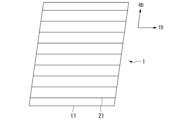
- FIG. 4 is a diagram showing an example of a state in which grooves are formed in the grain-oriented electrical steel sheet according to the embodiment.
- 2 is a schematic diagram of a groove and its periphery in a grain-oriented electrical steel sheet according to the present embodiment, viewed in a cross section perpendicular to the extension direction of the groove.
- FIG. 4 is a diagram showing an example of a state in which grooves are formed in the grain-oriented electrical steel sheet according to the embodiment.
- 2 is a schematic diagram of a groove and its periphery in a grain-oriented electrical steel sheet according to the present embodiment, viewed in a cross section perpendicular to the extension direction of the groove.
- This article describes a grain-oriented electromagnetic steel sheet according to one embodiment of the present invention (grain-oriented electromagnetic steel sheet according to this embodiment) and its manufacturing method.
- the grain-oriented electrical steel sheet 1 has a steel sheet (base steel sheet) 11 having a surface on which a plurality of grooves 21 are formed, the grooves 21 extending in a direction intersecting the rolling direction RD and having a depth in the sheet thickness direction.
- a forsterite coating or an insulating coating may be formed on the surface of the steel sheet (base steel sheet). Also, the insulating coating may be formed on the surface of the forsterite coating.
- the grain-oriented electrical steel sheet according to this embodiment may not only consist of a steel plate (base steel plate), but may also consist of a base steel plate and a forsterite coating formed on the surface of the base steel plate, or may consist of a base steel plate and an insulating coating formed on the surface of the base steel plate, or may consist of a base steel plate, a forsterite coating formed on the surface of the base steel plate, and an insulating coating formed on the surface of the forsterite coating.
- the forsterite coating and the insulating coating may be formed on one side or both sides. Each of these will be explained below.
- a steel sheet 11 has a plurality of grooves 21 formed on a surface thereof by laser irradiation, the grooves 21 extending in a direction intersecting a rolling direction RD and having a depth in a sheet thickness direction.
- the steel sheet is, for example, a cold-rolled sheet.
- Magnetic domain control can be achieved by forming linear grooves periodically in a direction intersecting with the rolling direction RD.
- grooves are formed on the surface of the steel sheet (in the case of grain-oriented electrical steel sheet in which a forsterite coating or an insulating coating is formed, this is the so-called base steel sheet excluding these).
- the direction intersecting the rolling direction RD is a direction at an angle of 60 to 120° with respect to the rolling direction RD.
- the shape of the groove is not limited as long as the effect of magnetic domain control can be obtained, but the depth is preferably 10 to 50 ⁇ m and the width is preferably 10 to 200 ⁇ m.
- the interval between adjacent grooves in the rolling direction RD is preferably 1 to 20 mm.
- the multiple grooves are preferably formed at approximately regular intervals (periodically) in the rolling direction RD so that they are approximately parallel to each other.
- the groove interval is the distance from the center of a groove in the width direction to the center of the adjacent groove in the width direction.
- protrusion As described above, in grain-oriented electrical steel sheets, the 180-degree magnetic domain width is subdivided by forming grooves in a direction intersecting the rolling direction RD of the steel sheet, and eddy current loss, which is part of the iron loss, is reduced accordingly.
- protrusions are formed due to the solidification of the molten material generated by the laser irradiation at the edge of the groove.
- These protrusions are usually composed of fine crystal grains with random crystal orientations other than the Goss orientation, so the presence of protrusions reduces the magnetic flux density of the steel sheet and increases the hysteresis loss, which is part of the iron loss, resulting in inferior characteristics.
- the protrusions are removed by brushing or the like after laser irradiation, but since the brushing is performed so as not to reduce the sheet thickness, it is difficult to completely remove the protrusions. Therefore, in the grain-oriented electrical steel sheet according to this embodiment, instead of removing the protrusions, the crystal orientation of the protrusions formed on the groove edges is controlled, and the area ratio of crystal grains whose crystal orientation is the Goss orientation (Goss orientation grains) in the protrusions is set to 10% or more, thereby suppressing an increase in hysteresis loss. If the area ratio of Goss orientation grains is less than 10%, the magnetic flux density of the steel sheet decreases and hysteresis loss, which is part of iron loss, increases.
- the adhesion of the coating may deteriorate in the areas where the protrusions are present. Therefore, in the grain-oriented electrical steel sheet according to this embodiment, it is preferable to control the roughness of the groove edge surface, including the protrusions. Specifically, it is preferable that the arithmetic mean roughness Ra of the surface along the extension direction of the groove, including the apex of the projection (the point where the projection height is maximum), is more than 2.0 ⁇ m and 5.0 ⁇ m or less. In this case, excellent coating adhesion can be obtained.
- Ra is 2.0 ⁇ m or less, the surface is too smooth and the effect of improving the coating adhesion cannot be obtained, whereas if Ra exceeds 5.0 ⁇ m, the surface is too rough and the coating is easily peeled off, and the effect of improving the coating adhesion cannot be obtained.
- the distance from the entrance 31 of the groove 21 (the position where the side of the groove, which is concave with respect to the reference plane, intersects with a virtual line extending the reference plane) to the entrance 31 of the opposite groove 21 is defined as the width of the groove 21, and the region from the entrance of the groove 21 of the steel plate 11 in the rolling direction RD in the opposite direction to the center of the groove 21 is defined as the groove edge 41, which is equal to the width of the groove 21.
- the region in the groove edge 41 where the width at the height of the reference plane RS (the length in the direction perpendicular to the height direction (the length of the dotted line in Figure 2)) is 1 ⁇ m or more and the protruding height from the reference plane RS is 1 ⁇ m or more is defined as the protrusion 101.
- the area ratio of the Goss oriented crystal grains of the protrusions 101 can be increased by a manufacturing method including a grinding step described later.
- the Ra of the groove edge including the apex of the protrusion can be controlled by a manufacturing method including a grinding step described later.
- the area ratio of crystal grains whose crystal orientation of the projections on the groove edge is the Goss orientation is determined by the following method. First, a sample is taken from the grain-oriented electrical steel sheet to be measured so that a cross section perpendicular to the longitudinal direction (extending direction) of the groove is exposed. At that time, the cross section is taken so that the groove and the groove edge are included. The cross section is polished to reveal a cross section including the groove and its surrounding area as shown in Figure 2, and then the cross section is observed. A total of 10 or more cross sections are observed, and when one or more protrusions are present on the edge of the groove, it is determined that at least one protrusion is present.
- the crystal orientation of the protrusions is measured by the electron backscattering diffraction pattern (EBSD) method.
- Grains with an orientation difference of 10° or less from the accurate Goss orientation ⁇ 110 ⁇ 001> are defined as Goss-oriented grains, and the area ratio of the Goss-oriented grains of the protrusions is calculated.
- the area ratio of the Goss-oriented grains is calculated for each protrusion, and the average value of these is taken as the area ratio of the Goss-oriented grains.
- the EBSD measurement conditions are as follows.
- the arithmetic mean roughness Ra of the surface of the groove edge including the apexes of the projections is determined by the following method.
- a laser type surface roughness measuring device is used to obtain a height distribution on the steel sheet surface within a range of 1000 ⁇ m in the groove extension direction and 400 ⁇ m from the groove center (200 ⁇ m on one side of the groove) in a direction perpendicular to the groove extension direction.
- the laser spot diameter is set to 0.40 ⁇ m or less (e.g., 0.40 ⁇ m)
- scanning is performed in steps of 0.30 ⁇ m or less (e.g., 0.30 ⁇ m)
- the measurement accuracy in the height direction is set to 0.10 ⁇ m or less
- the magnification of the objective lens is set to 50 times.
- the point where the height is maximum is determined as the apex of the protrusion.
- a measured cross-sectional curve is obtained for a cross section including the apex of the protrusion, parallel to the extension direction of the groove and parallel to the thickness direction of the steel plate.
- a low-pass filter with a cutoff value ⁇ s and a wide-pass filter with a cutoff value ⁇ c are applied to the measured cross-sectional curve to obtain a roughness curve.
- the arithmetic average roughness Ra is obtained from this roughness curve in accordance with JIS B 0601 (2013).
- the cutoff values ⁇ s and ⁇ c are determined by the type and objective lens of the laser surface roughness measuring instrument.
- the chemical composition of the base steel sheet is not limited, and may be the same as that of the base steel sheet of a known grain-oriented electrical steel sheet.
- the base steel sheet may contain, in mass%, Si: 2.5 to 4.5%, Mn: 0.01 to 0.15%, C: 0 to 0.085%, acid-soluble Al: 0 to 0.065%, N: 0 to 0.012%, Cr: 0 to 0.30%, Cu: 0 to 0.40%, P: 0 to 0.50%, Sn: 0 to 0.30%, Sb: 0 to 0.30%, Ni: 0 to 1.000%, S: 0 to 0.015%, Se: 0 to 0.015%, and Bi: 0 to 0.02%.
- the base steel sheet may contain the above, with the balance being Fe and impurities.
- the chemical composition of the base steel sheet can be said to be the chemical composition of the grain-oriented electrical steel sheet.
- the chemical composition of the base steel plate may be measured by a general analysis method for steel.
- the chemical composition of the base steel plate may be measured using ICP-AES (Inductively Coupled Plasma-Atomic Emission Spectrometry).
- ICP-AES Inductively Coupled Plasma-Atomic Emission Spectrometry
- a test piece 35 mm square 35 mm in both the rolling direction and width direction
- the composition may be identified by measuring it under conditions based on a calibration curve created in advance using a measuring device such as Shimadzu's ICPS-8100.
- C and S which are difficult to measure using ICP-AES, may be measured using the combustion-infrared absorption method, and N may be measured using the inert gas fusion-thermal conductivity method.
- the chemical composition of the base steel sheet can be analyzed after removing the forsterite coating and insulating coating from the grain-oriented electrical steel sheet by a known method such as pickling.
- the thickness of the base steel sheet of the grain-oriented electrical steel sheet according to this embodiment is not limited, but from the viewpoint that a thinner sheet thickness reduces eddy current loss, it is preferable that the thickness be, for example, 0.15 to 0.35 mm.
- a forsterite coating may be formed on the surface of the steel sheet that serves as the base steel sheet.
- the forsterite coating is an inorganic coating mainly composed of magnesium silicate, and is formed by a reaction between an annealing separator containing magnesia (MgO) applied to the surface of the base steel sheet and the components of the surface of the base steel sheet during finish annealing, and has a composition derived from the components of the annealing separator and the base steel sheet (more specifically, a composition mainly composed of Mg 2 SiO 4 ).
- MgO magnesia
- the forsterite film may not be formed.
- an insulating coating may be formed on the surface of the base steel sheet or on the surface of the forsterite coating.
- the insulating coating reduces eddy current loss by imparting electrical insulation to the grain-oriented electrical steel sheet, thereby reducing iron loss in the grain-oriented electrical steel sheet.
- the insulating coating has the function of applying tension to the grain-oriented electrical steel sheet. By applying tension to the grain-oriented electrical steel sheet and facilitating domain wall movement in the grain-oriented electrical steel sheet, the iron loss of the grain-oriented electrical steel sheet can be reduced.
- the insulating coating also provides various other properties such as corrosion resistance, heat resistance, and slipperiness.
- the insulating coating may be a known coating formed, for example, by applying a coating solution containing phosphate and colloidal silica as main components to the surface of the forsterite coating and baking it.
- the grain-oriented electrical steel sheet according to this embodiment can obtain its effects as long as it has the above-mentioned characteristics regardless of the manufacturing method, but a manufacturing method including the following steps is preferable because it can be stably manufactured.
- a hot rolling step of heating and hot rolling the slab to obtain a hot-rolled sheet
- a hot-rolled sheet annealing process for annealing the hot-rolled sheet after the hot rolling process
- the method for producing a grain-oriented electrical steel sheet according to this embodiment may further include one or both of the following steps.
- (VIII) a nitriding process for increasing the nitrogen content of the steel sheet after the decarburization annealing process;
- (IX) An insulating coating forming step of forming an insulating coating on the surface of the steel sheet (or the surface of the forsterite coating formed on the surface of the steel sheet) after the final annealing step.
- the manufacturing method of the grain-oriented electrical steel sheet according to the present embodiment is characterized by the groove forming step and the grinding step, while the hot rolling step, the hot-rolled sheet annealing step, the cold rolling step, the decarburization annealing step, the nitriding treatment step, the finish annealing step, and the insulating coating forming step are not particularly limited and can be performed under known conditions. Preferred conditions are described below. Even if conditions are not described, the reaction can be carried out under known conditions.
- a slab having a predetermined chemical composition (a chemical composition corresponding to the chemical composition of the base steel sheet of the grain-oriented electrical steel sheet according to this embodiment) is heated and hot rolled to form a hot-rolled sheet.
- the conditions are not limited, but the heating temperature is, for example, 1050 to 1400°C.
- the chemical composition of the slab to be subjected to hot rolling may be determined according to the desired chemical composition of the grain-oriented electrical steel sheet, taking into consideration changes in the chemical composition in each process. For example, when obtaining the chemical composition of the base steel sheet of the grain-oriented electrical steel sheet according to the above-mentioned preferred embodiment, it is preferable to use a slab having the following chemical composition.
- the method for obtaining the slab is not limited.
- molten steel having a predetermined chemical composition may be melted and the molten steel may be used to produce the slab.
- the slab may be produced by a continuous casting method, or the molten steel may be used to produce an ingot and the ingot may be bloomed to produce the slab.
- the slab may be produced by other methods.
- the thickness of the slab is not particularly limited, but is, for example, 150 to 350 mm.
- the thickness of the slab is preferably 220 to 280 mm. A so-called thin slab having a thickness of 10 to 70 mm may also be used.
- the hot-rolled sheet annealing process In the hot-rolled sheet annealing process, the hot-rolled sheet after the hot rolling process is annealed. By carrying out such annealing treatment, recrystallization occurs in the steel sheet structure, making it possible to realize good magnetic properties.
- the hot-rolled sheet manufactured through the hot rolling process may be annealed according to a known method.
- the means for heating the hot-rolled sheet during annealing is not particularly limited, and known heating methods can be adopted.
- the annealing conditions are also not particularly limited, but for example, the hot-rolled sheet can be annealed in a temperature range of 900 to 1200 ° C. for 10 seconds to 5 minutes.
- the cold rolling process In the cold rolling process, the hot rolled sheet after the hot rolled sheet annealing process is pickled and cold rolled to obtain a cold rolled sheet.
- the cold rolling may be a single cold rolling (a series of cold rolling without intermediate annealing) or may be multiple cold rollings with intermediate annealing by interrupting the cold rolling and performing at least one or two or more intermediate annealings before the final pass of the cold rolling process.
- the cold rolling conditions may be in accordance with known methods.
- the final rolling reduction may be in the range of 80% to 95%.
- the final rolling reduction is the cumulative rolling reduction of cold rolling, and in the case where intermediate annealing is performed, it is the cumulative rolling reduction of cold rolling after final intermediate annealing.
- the temperature is maintained at 1000 to 1200° C. for 5 to 180 seconds, for example.
- the annealing atmosphere is not particularly limited. In consideration of the manufacturing cost, the number of times of intermediate annealing is preferably three or less.
- the pickling may also be carried out under known conditions.
- a cold-rolled sheet (a steel sheet after cold rolling) is irradiated with a laser to form grooves on the surface.
- a method is preferred in which a laser is irradiated while scanning in a groove forming direction (a direction intersecting with the rolling direction) to melt a part of the steel sheet surface and remove the molten material from the surface to form the grooves. Examples of a method for removing the molten material from the surface include spraying an assist gas.
- the laser irradiation is preferably performed multiple times while moving in the width direction so that the grooves are arranged approximately parallel to each other at regular intervals (for example, 1 to 10 mm) in the rolling direction.
- the laser irradiation conditions are not limited, but in order to form a groove of a predetermined shape (e.g., a depth of 10 to 50 ⁇ m and a groove width of 10 to 200 ⁇ m), it is preferable that the laser output is 200 to 3000 W, the laser focusing spot diameter in the rolling direction (i.e., the diameter including 86% of the laser output) is 10 to 1000 ⁇ m, the laser focusing spot diameter in the plate width direction (i.e., the diameter including 86% of the laser output) is 10 to 1000 ⁇ m, and the laser scanning speed is 5 to 50 m/s.
- the magnetic domain width is subdivided, improving the magnetic properties.
- ⁇ Grinding process In the grinding process, the surface of the steel sheet after the groove forming process is ground using a brush roll with abrasive grains fixed thereto. By performing grinding under appropriate conditions, it is possible to impart distortion to the protrusions formed at the groove edge while avoiding a decrease in sheet thickness (part of the protrusions is removed by grinding, but part remains). The driving force of recrystallization of the distortion-imparted protrusions is increased, and primary recrystallization and grain growth occur in the subsequent decarburization annealing process, making them susceptible to encroachment into the Goss orientation during finish annealing.
- the distortion-imparted protrusions undergo secondary recrystallization during finish annealing, increasing the area ratio of Goss orientation grains (normally, the area ratio of Goss orientation grains is less than 5% if there is no distortion and random recrystallization, but by going through the grinding process, it becomes 10% or more).
- the steel plate is moved at a transport speed of 20 to 150 meters per minute (mpm) while grinding is performed using a brush roll that rotates in a direction opposite to the transport direction of the steel plate at the position where it comes into contact with the steel plate under the following conditions: the rotation speed of the brush roll is 500 to 1500 rpm, the pressing amount of the brush roll is 1.0 to 5.0 mm, the grain size of the abrasive grains is #60 to #400, and the diameter of the brush roll is 200 to 500 mm.
- the rotation speed of the brush roll is 500 to 1500 rpm
- the pressing amount of the brush roll is 1.0 to 5.0 mm
- the grain size of the abrasive grains is #60 to #400
- the diameter of the brush roll is 200 to 500 mm.
- the conveying speed (line speed) of the steel sheet is less than 20 mpm, the amount of grinding is too large, resulting in a reduction in sheet thickness, whereas if it exceeds 150 mpm, the amount of strain imparted by grinding is insufficient, resulting in a failure to increase the area ratio of Goss oriented grains.
- the rotation speed of the brush roll is less than 500 rpm, the amount of distortion imparted by grinding is insufficient, and the area ratio of Goss-oriented grains does not increase, whereas if the rotation speed exceeds 1500 rpm, the amount of grinding is too large, resulting in a decrease in plate thickness.
- the reduction amount of the brush roll is less than 1.0 mm, the amount of distortion imparted by grinding is insufficient, and the area ratio of Goss oriented grains does not increase, whereas if it exceeds 5.0 mm, the amount of grinding is too large, resulting in a reduction in plate thickness. If the grain size of the abrasive grains is less than #60, the amount of grinding is too large, resulting in a reduction in the plate thickness, whereas if the grain size is more than #400, the amount of strain imparted by grinding is insufficient, and the area ratio of Goss oriented grains does not increase.
- the conveying speed of the steel plate is 20 to 150 mpm
- the rotation speed of the brush roll is 500 to 1000 rpm
- the pressing amount of the brush roll is 1.0 to 4.0 mm
- the grain size of the abrasive grains is #100 to 400
- the diameter of the brush roll is 200 to 500 mm.
- the brush roll reduction amount is 1.0 to 2.0 mm.
- decarburization annealing process In the decarburization annealing process, the steel sheet after the grinding process is subjected to decarburization annealing, which removes carbon that adversely affects the magnetic properties from the steel sheet (decarburization) and causes primary recrystallization of the steel sheet.
- the decarburization annealing conditions are not limited, but may be conditions of heating to 700 to 900° C. and holding for 1 to 3 minutes.
- a nitriding treatment may be performed to increase the nitrogen content of the grain-oriented electrical steel sheet.
- the nitriding treatment may be performed by a known method, for example, by annealing in an atmosphere containing a nitriding gas such as ammonia, thereby allowing nitrogen to penetrate into the steel. This allows the formation of an inhibitor of secondary recrystallization by nitriding.
- an annealing separator is applied to the steel sheet after the decarburization annealing process, and the steel sheet is then final annealed. Since the final annealing is performed after the steel sheet is wound into a coil, an annealing separator is applied to the steel sheet during the final annealing to prevent the steel sheet from seizing.
- the annealing separator generally used is mainly composed of MgO or Al 2 O 3. The final annealing is performed after applying such an annealing separator. For example, when an annealing separator containing MgO is used, a forsterite (Mg 2 SiO 4 ) coating layer is formed.
- the forsterite coating may not be formed.
- the material is heated to an annealing temperature to cause secondary recrystallization of the primary recrystallized grains obtained in the decarburization annealing process, thereby obtaining crystal grains aligned in the Goss orientation, and impurities (N, S, etc.) that adversely affect the magnetic properties are removed (purified) by holding the material at the annealing temperature for a predetermined time.
- the driving force for recrystallization is increased by the strain introduced in the grinding process in the steel sheet to be subjected to decarburization annealing, and primary recrystallization and grain growth occur in the decarburization annealing process, resulting in a state in which the Goss orientation is easily encroached upon during finish annealing. Therefore, the area ratio of crystal grains having the Goss orientation in the protrusions increases.
- the conditions for the finish annealing are not limited, but examples include heating to 1100 to 1300° C. and holding for 20 to 24 hours.
- an insulating coating is formed on the steel sheet after the final annealing step (on the surface of the forsterite coating, if a forsterite coating has been formed on the surface of the steel sheet by final annealing).
- the insulating coating can be formed by applying a coating solution containing phosphoric acid or a phosphate, colloidal silica, and chromic anhydride or a chromate to a steel sheet after finish annealing (including the case where the steel sheet has a forsterite coating), and baking and drying the applied solution at 300 to 950° C. for 10 seconds or more. Through these steps, a grain-oriented electrical steel sheet can be obtained which includes a base steel sheet and, as necessary, a forsterite coating and/or an insulating coating.
- the slab had a chemical composition containing, by mass fraction, 3.3% Si, 0.060% C, 0.028% acid-soluble Al, 0.008% N, 0.12% Mn, 0.05% Cr, 0.04% Cu, 0.01% P, 0.02% Sn, 0.005% Ni, 0.007% S, with the balance being Fe and impurities.
- the slab was subjected to a hot rolling process to form a hot-rolled sheet having a thickness of 2.6 mm. This hot-rolled sheet was annealed by heating to 1000° C. and holding for 1 minute. The hot-rolled sheet after annealing was pickled and cold-rolled under the condition of a final rolling reduction of 91% to obtain a steel sheet (cold-rolled sheet) having a sheet thickness of 0.23 mm.
- This steel sheet was irradiated with a laser under the conditions of a laser output of 1500 W, a laser focused spot diameter of 40 ⁇ m in the rolling direction, a laser focused spot diameter of 40 ⁇ m in the sheet width direction, and a scanning speed of 45 m/s to form grooves on the surface that extended in a direction at an angle of 90° to the rolling direction, had a width of 40 ⁇ m, and a depth of 30 ⁇ m. A plurality of these grooves were formed in parallel at intervals of 5 mm in the rolling direction.
- the surface of the steel plate with the grooves formed thereon was ground under the conditions shown in Table 1 using a brush roll rotating in the direction opposite to the conveyance direction of the steel plate. After grinding, the specimen was heated to 800° C.
- An annealing separator mainly composed of magnesia (MgO) was applied to the steel sheet after decarburization annealing, and the steel sheet was subjected to finish annealing under the conditions of heating to 1200°C and holding for 20 hours.
- MgO magnesia
- a coating solution containing colloidal silica and phosphate was applied to the obtained grain-oriented electrical steel sheet, and a heat treatment was carried out under conditions of heating to 850° C. and holding for 1 minute to form an insulating coating.
- the chemical composition of the base steel sheet of the obtained grain-oriented electrical steel sheet was determined to be, by mass fraction, Si: 3.3%, C: 0.001% or less, acid-soluble Al: 0.004% or less, N: 0.001% or less, Mn: 0.12%, Cr: 0.05%, Cu: 0.04%, P: 0.01%, Sn: 0.02%, Ni: 0.005%, S: 0.001% or less, with the remainder being Fe and impurities.
- the area ratio of Goss oriented grains in the protrusions of the obtained grain-oriented electrical steel sheets was determined by the EBSD method in the manner described above. Further, in the manner described above, a measured cross-sectional curve of a cross section including a surface that includes the apex of the protrusion, is parallel to the extension direction of the groove and is parallel to the thickness direction of the steel plate was obtained, and the arithmetic mean roughness Ra was calculated in accordance with JIS B 0601 (2013) from the roughness curve obtained from this measured cross-sectional curve. The results are shown in Table 1.
- the adhesion of the insulating coating to the obtained grain-oriented electrical steel sheets was evaluated by the following method.
- a test piece measuring the sheet thickness ⁇ 80 mm ⁇ 80 mm was cut out from a portion including the groove edge of the obtained grain-oriented electrical steel sheet, and this test piece was wound around a round bar having a diameter of 20 mm and then flattened.
- the surface of the test piece after being flattened was observed, and the area of the insulating coating that had not peeled off from the steel sheet relative to the area of the bent part was measured to calculate the remaining coating area ratio (%).
- the insulation coating adhesion of the test pieces with a coating remaining area ratio of 95% or more was rated as “excellent,” the insulation coating adhesion of the test pieces with a coating remaining area ratio of 90% or more but less than 95% was rated as “good,” and the insulation coating adhesion of the test pieces with a coating remaining area ratio of less than 90% was rated as “poor.”
- the present invention provides a grain-oriented electrical steel sheet with sufficiently high magnetic flux density and low core loss, and a manufacturing method thereof. Therefore, it has high industrial applicability.
Landscapes
- Engineering & Computer Science (AREA)
- Chemical & Material Sciences (AREA)
- Physics & Mathematics (AREA)
- Mechanical Engineering (AREA)
- Organic Chemistry (AREA)
- Metallurgy (AREA)
- Materials Engineering (AREA)
- Crystallography & Structural Chemistry (AREA)
- Power Engineering (AREA)
- Thermal Sciences (AREA)
- Optics & Photonics (AREA)
- Electromagnetism (AREA)
- Manufacturing & Machinery (AREA)
- Plasma & Fusion (AREA)
- Dispersion Chemistry (AREA)
- Manufacturing Of Steel Electrode Plates (AREA)
- Soft Magnetic Materials (AREA)
Abstract
Description
本願は、2022年11月22日に、日本に出願された特願2022-186164号に基づき優先権を主張し、その内容をここに援用する。
低鉄損化をする方法の一つとして、レーザ照射を行う技術が提案されている。この技術では、レーザ照射により表面に歪が導入され、180°磁区幅が細分化されることで鉄損の一部である渦電流損を低減することができるとされている。
特許文献1では、容易に、かつ高い生産性を確保しながら、方向性電磁鋼板のL方向及びC方向の両方向における鉄損を低減することができることが示されている。
そのため、鋼板表面に溝を形成することによっても、歪導入と同様に180°磁区幅を細分化し渦電流損を低減することが提案されている。
例えば、特許文献2には、レーザビームを制御して照射し、圧延方向幅0.5mm以下、深さ10μm以上の凹部を形成する、歪取焼鈍を適用可能な方向性電磁鋼板の鉄損特性を改善する方法が開示されている。
しかしながら、上記のように、レーザ照射により溝を形成する場合、レーザ照射で発生した溶融物が溝縁部などで凝固することによって突起が形成される。この突起は通常Goss方位以外のランダムな結晶方位をもつ微細結晶粒にて構成される。そのため、突起が存在すると鋼板の磁束密度が低下し鉄損の一部であるヒステリシス損が増大し、特性は劣位となる。
上記突起はレーザ照射後にブラシ処理等を行うことで、ある程度除去される。しかしながら、ブラシ処理等を行うとしても、板厚を減少させないように行われるので、突起を完全に除去することは難しい。特許文献2ではこのような突起について考慮されていない。
また、溝縁部に突起がある場合、被膜の密着性が劣化することも懸念される。しかしながら、従来、突起がある場合の被膜密着性についても十分な検討はなされていない。
また、突起がある場合でも十分な被膜密着性が得られる方向性電磁鋼板を提供することを好ましい課題とする。
その結果、溝縁部に形成される突起の結晶方位を、Goss方位となる割合が高くなるように制御することでヒステリシス損の増大を抑制できることを見出した。
また、溝縁部の突起の結晶方位について、レーザ照射によって鋼板の表面に溝を形成する溝が形成された後、所定の条件で鋼板の表面を研削することで、後の焼鈍の際に、突起の結晶方位がGoss方位となる割合を高めることができることを見出した。
また、研削の条件を制御して表面粗さを所定の範囲とすれば、被膜密着性をより改善できることも見出した。
[1]本発明の一態様に係る方向性電磁鋼板は、表面に圧延方向と交差する方向に延在し且つ深さが板厚方向となる溝が複数形成された鋼板を有し、前記圧延方向に平行かつ前記板厚方向に平行な断面において、溝の入り口部から反対の溝の入り口部までの距離を溝の幅とし、前記鋼板の前記溝の入り口部から、前記圧延方向に、溝の中心とは反対方向に、前記溝の幅と同等の領域を溝縁部とし、前記溝の入り口部から、前記圧延方向に、前記溝の中心とは反対方向に、前記溝の幅よりも離れた領域における表面を基準面としたとき、前記溝縁部に、幅が1μm以上かつ、前記基準面からの突出高さが1μm以上である領域である突起が存在し、前記突起のうち、Goss方位粒の面積率が10%以上である。
[2][1]に記載の方向性電磁鋼板では、前記鋼板の前記溝縁部の、前記突起の頂点を含む溝の延在方向に沿った表面の算術平均粗さRaが、2.0μm超、5.0μm以下であってもよい。
[3][1]または[2]に記載の方向性電磁鋼板では、前記鋼板の前記表面に、フォルステライト被膜が形成されていてもよい。
[4][3]に記載の方向性電磁鋼板では、前記フォルステライト被膜の表面に、絶縁被膜が形成されていてもよい。
[5][1]または[2]に記載の方向性電磁鋼板では、前記鋼板の前記表面に、絶縁被膜が形成されていてもよい。
[6]本発明の別の態様に記載の方向性電磁鋼板の製造方法は、[1]に記載の方向性電磁鋼板の製造方法であって、鋼板にレーザ照射を施すことにより表面に溝を形成する溝形成工程と、前記溝形成工程後に、前記鋼板の表面を、砥粒が固定されたブラシロールを用いて研削する研削工程と、を含み、前記研削工程では、前記ブラシロールは、前記鋼板と当接する位置では、前記鋼板の搬送方向と対向する方向に回転し、前記鋼板の搬送速度が20~150mpmであり、前記ブラシロールの回転数が500~1500rpmであり、前記ブラシロールの圧下量が1.0~5.0mmであり、前記砥粒の粒度が♯60~♯400であり、前記ブラシロールの径が200~500mmである。
[7][6]に記載の方向性電磁鋼板の製造方法は、前記ブラシロールの前記圧下量が、1.0~2.0mmであってもよい。
図1に示すように、本実施形態に係る方向性電磁鋼板1は、表面に、圧延方向RDと交差する方向に延在し且つ深さが板厚方向となる溝21が複数形成された鋼板(母材鋼板)11を有している。
鋼板(母材鋼板)の表面には、フォルステライト被膜または絶縁被膜が形成されていてもよい。また、絶縁被膜はフォルステライト被膜の表面に形成されていてもよい。
すなわち、本実施形態に係る方向性電磁鋼板は、鋼板(母材鋼板)からなる場合だけでなく、母材鋼板と母材鋼板の表面に形成されたフォルステライト被膜からなっていてもよく、母材鋼板と母材鋼板の表面に形成された絶縁被膜からなっていてもよく、または、母材鋼板と母材鋼板の表面に形成されたフォルステライト被膜とフォルステライト被膜の表面に形成された絶縁被膜とからなっていてもよい。
フォルステライト被膜及び絶縁被膜は片面に形成されていてもよいが、両面に形成されていてもよい。
以下それぞれについて説明する。
(溝)
図1に示すように、鋼板11は、表面に、レーザ照射によって形成された、圧延方向RDと交差する方向に延在し且つ深さが板厚方向となる溝21を複数有する。鋼板は、例えば冷延板である。
圧延方向RDと交差する方向に周期的に線状の溝を形成することで、磁区制御を行うことができる。本実施形態に係る方向性電磁鋼板では、この効果を得るため、鋼板(フォルステライト被膜や絶縁被膜が形成されている方向性電磁鋼板においては、これらを除いたいわゆる母材鋼板)の表面に溝が形成されている。
ここで圧延方向RDに交差する方向は、圧延方向RDに対して60~120°の方向である。
溝の形状については磁区制御の効果が得られる範囲であれば限定されないが、深さが、10~50μm、幅が10~200μmであることが好ましい。複数の溝のうち、隣り合う溝の圧延方向RDの間隔が、1~20mmであることが好ましい。複数の溝は圧延方向RDに略一定の間隔で(周期的に)それぞれが略平行になるように形成されていることが好ましい。溝の間隔とは、溝の幅方向の中心から隣の溝の幅方向の中心までの距離である。
上記の通り、方向性電磁鋼板では鋼板の圧延方向RDに交差する方向に溝を形成することで180度磁区幅が細分化され、それに伴い鉄損の一部である渦電流損が低減されるが、レーザ照射により溝を形成する場合、レーザ照射で発生した溶融物が溝縁部で凝固することによる突起が形成される。この突起は通常Goss方位以外のランダムな結晶方位をもつ微細結晶粒にて構成されているため、突起が存在すると鋼板の磁束密度が低下し鉄損の一部であるヒステリシス損が増大し、特性は劣位となる。上記突起はレーザ照射後のブラシ処理等により除去されるが、板厚を減少させないようにブラシ処理を行うため、突起を完全に除去することは難しい。
そのため、本実施形態に係る方向性電磁鋼板では、突起を除去するのではなく、溝縁部に形成された突起の結晶方位を制御し、突起に占める結晶方位がGoss方位となる結晶粒(Goss方位粒)の面積率を10%以上とすることで、ヒステリシス損の増加を抑制する。Goss方位粒の面積率が10%未満では、鋼板の磁束密度が低下し鉄損の一部であるヒステリシス損が増大する。
具体的には、突起の頂点(突出高さが最大となる点)を含む溝の延在方向に沿った表面の算術平均粗さRaを、2.0μm超、5.0μm以下とすることが好ましい。この場合、優れた被膜密着性が得られる。
Raが2.0μm以下では、表面が平滑であるため被膜密着性の向上効果が得られない。一方、Raが5.0μm超では、表面が粗すぎるため被膜が剥離しやすく、被膜密着性の向上効果が得られない。
突起101のGoss方位の結晶粒の面積率は、後述する研削工程を含む製造方法によって高めることができる。突起の頂点を含む溝縁部のRaは、後述する研削工程を含む製造方法によって制御できる。
まず、測定対象となる方向性電磁鋼板から、溝の長手方向(延在方向)に直交する断面が露出するようにサンプルを採取する。その際、断面には、溝と溝縁部とが含まれるように採取する。
断面を研磨することにより、図2に示すような溝とその周辺部を含む断面を現出させた後、その断面を観察する。合計10ヶ所以上の断面を観察し、溝縁部に一つ以上の突起が存在する場合に、少なくとも一つの突起が存在すると判断する。
また、突起が存在する場合、その突起の結晶方位を、後方散乱電子回折(Electron Back Scattering Diffraction Pattern:EBSD)法によって、測定する。正確なGoss方位{110}<001>との方位差が10°以内のものをGoss方位粒と定義し、突起のGoss方位粒の面積率を求める。観察した断面に突起が複数存在する場合は、各々の突起について、Goss方位粒の面積率を求め、それらの平均値をGoss方位粒の面積率とする。
EBSDの測定条件は次の通りとする。
(a)測定装置:FE-SEM「SU-70」(日立ハイテク社製)
EBSD装置「DigiView」(TSLソリューションズ社製)
(b)倍率:500倍
(c)ステップ間隔:0.25μm
(d)測定領域:溝長手方向と交差する方向に200μm×板厚方向に70μm
レーザ式表面粗さ測定器を用いて鋼板表面の、溝の延在方向に1000μm、溝の延在方向に直交する方向に、溝を中心に400μm(溝の片側に200μm)の範囲で高さ分布を得る。この測定では、レーザスポット径を0.40μm以下(例えば0.40μm)として、0.30μm以下(例えば0.30μm)のステップで走査し、高さ方向の測定精度を0.10μm以下とし、対物レンズの倍率を50倍とする。
この測定の結果、高さが最大となる点を突起の頂点とする。そして、突起の頂点を含み溝の延在方向に平行かつ鋼板の板厚方向に平行な面を含む断面の、測定断面曲線を得る。測定断面曲線にカットオフ値λsの低域フィルタとカットオフ値λcの広域フィルタを適用して、粗さ曲線を得る。この粗さ曲線から算術平均粗さRaをJIS B 0601(2013)に準じて求める。
その際、カットオフ値λs及びλcは、レーザ式表面粗さ測定器の型式及び対物レンズにより決定する。本実施形態においては、キーエンス社製のVK-9700にて対物レンズの倍率を50倍として粗さを測定した際のカットオフ値として、λs=0.8μm、λc=0.08mmを用いる。
母材鋼板の化学組成は限定されず、公知の方向性電磁鋼板の母材鋼板と同等であればよい。例えば、質量%で、Si:2.5~4.5%、Mn:0.01~0.15%、C:0~0.085%、酸可溶性Al:0~0.065%、N:0~0.012%、Cr:0~0.30%、Cu:0~0.40%、P:0~0.50%、Sn:0~0.30%、Sb:0~0.30%、Ni:0~1.000%、S:0~0.015%、Se:0~0.015%、Bi:0~0.02%を含有することができる。また、上記を含有し、残部がFe及び不純物であってもよい。
方向性電磁鋼板が母材鋼板からなる(フォルステライト被膜や絶縁被膜を有していない)場合には、母材鋼板の化学組成は、方向性電磁鋼板の化学組成であると言える。
本実施形態に係る方向性電磁鋼板の母材鋼板の板厚は限定されないが、板厚が薄い方が、渦電流損が低減されるという観点から、例えば0.15~0.35mmであることが好ましい。
本実施形態に係る方向性電磁鋼板では、母材鋼板となる鋼板の表面にフォルステライト被膜が形成されていてもよい。
フォルステライト被膜は、ケイ酸マグネシウムを主成分とする無機質の被膜である。フォルステライト被膜は、仕上げ焼鈍において、母材鋼板の表面に塗布されたマグネシア(MgO)を含む焼鈍分離剤と母材鋼板の表面の成分とが反応することにより形成され、焼鈍分離剤及び母材鋼板の成分に由来する組成(より詳細には、Mg2SiO4を主成分とする組成)を有する。
一方、仕上げ焼鈍において、Al2O3を主体とする焼鈍分離剤を用いた場合には、フォルステライト被膜は形成されない場合がある。
本実施形態に係る方向性電磁鋼板では、母材鋼板の表面に、またはフォルステライト被膜の表面に、絶縁被膜が形成されていてもよい。
絶縁被膜は、方向性電磁鋼板に電気絶縁性を付与することで渦電流損を低減して、方向性電磁鋼板の鉄損を低減する。絶縁被膜は、方向性電磁鋼板に張力を付与するという機能を有する。方向性電磁鋼板に張力を付与して、方向性電磁鋼板における磁壁移動を容易にすることで、方向性電磁鋼板の鉄損を低減することができる。
また、絶縁被膜によれば、上記のような電気絶縁性以外にも、耐蝕性、耐熱性、すべり性といった種々の特性が得られる。
本実施形態に係る方向性電磁鋼板では、絶縁被膜は、例えば、リン酸塩とコロイダルシリカとを主成分とするコーティング溶液をフォルステライト被膜の表面に塗布し、焼付けることによって形成される公知の被膜であってよい。
本実施形態に係る方向性電磁鋼板は、製造方法によらず上記の特徴を有していれば、その効果は得られるが、以下の工程を含む製造方法であれば安定して製造できるので好ましい。
(I)スラブを加熱して、熱間圧延して、熱延板とする熱間圧延工程と、
(II)前記熱間圧延工程後の前記熱延板を焼鈍する熱延板焼鈍工程と、
(III)前記熱延板焼鈍工程後の前記熱延板を、酸洗し、冷間圧延して鋼板(冷延板)とする冷間圧延工程と、
(IV)前記鋼板にレーザ照射を施すことにより表面に溝を形成する溝形成工程と、
(V)前記溝形成工程後の前記鋼板の表面を砥粒が固定されたブラシロールを用いて研削する研削工程と、
(VI)前記研削工程後の前記鋼板に、脱炭焼鈍を行う脱炭焼鈍工程と、
(VII)前記脱炭焼鈍工程後の前記鋼板に焼鈍分離剤を塗布し、仕上げ焼鈍する仕上げ焼鈍工程。
また、本実施形態に係る方向性電磁鋼板の製造方法はさらに、以下の工程のいずれかまたは両方を有していてもよい。
(VIII)前記脱炭焼鈍工程後の前記鋼板の窒素含有量を増加させる窒化処理工程と、
(IX)前記仕上げ焼鈍工程後の前記鋼板の表面(または前記鋼板の表面に形成されたフォルステライト被膜の表面)に、絶縁被膜を形成する絶縁被膜形成工程。
以下、好ましい条件について説明する。説明しない条件についても、公知の条件で行うことができる。
熱間圧延工程では、所定の化学組成(本実施形態に係る方向性電磁鋼板の母材鋼板の化学組成に応じた化学組成)を有するスラブを、加熱して、熱間圧延して熱延板とする。
その条件は、限定されないが、例えば、加熱温度は1050~1400℃である。
例えば、上述した好ましい本実施形態に係る方向性電磁鋼板の母材鋼板の化学組成を得る場合、以下の化学組成を有するスラブを用いることが好ましい。
質量%で、Si:2.5~4.5%、Mn:0.01~0.15%、C:0.02~0.10%、酸可溶性Al:0~0.065%、N:0.002~0.030%、Cr:0~0.30%、Cu:0~0.40%、P:0~0.50%、Sn:0~0.30%、Sb:0~0.30%、Ni:0~1.000%、S:0.001~0.050%、Se:0~0.050%、Bi:0~0.02%を含有することができる。また、上記を含有し、残部がFe及び不純物であってもよい。
スラブの厚さは、特に限定されないが、たとえば、150~350mmである。スラブの厚さは好ましくは、220~280mmである。厚さが10~70mmの、いわゆる薄スラブを用いてもよい。
熱延板焼鈍工程では、熱間圧延工程後の前記熱延板を焼鈍する。このような焼鈍処理を施すことで、鋼板組織に再結晶が生じ、良好な磁気特性を実現することが可能となる。
本実施形態の熱延板焼鈍工程では、公知の方法に従い、熱間圧延工程を経て製造された熱延板を焼鈍すればよい。焼鈍に際して熱延板を加熱する手段については、特に限定されるものではなく、公知の加熱方式を採用することが可能である。また、焼鈍条件についても、特に限定されるものではないが、例えば、熱延板に対して、900~1200℃の温度域で10秒~5分間の焼鈍を行うことができる。
冷間圧延工程では、熱延板焼鈍工程後の熱延板を、酸洗し、冷間圧延して冷延板とする。冷間圧延は、一回の(中間焼鈍を挟まない一連の)冷間圧延でもよく、冷延工程の最終パスの前に、冷延を中断し少なくとも1回または2回以上の中間焼鈍を実施して、中間焼鈍をはさむ複数回の冷間圧延を施してもよい。
冷間圧延の条件、公知の方法に従えばよい。例えば、最終圧下率は、80%以上95%以下の範囲内とすることができる。
最終圧下率とは、冷間圧延の累積圧下率であり、中間焼鈍を行う場合には、最終中間焼鈍後の冷間圧延の累積圧下率である。
中間焼鈍を行う場合、例えば、1000~1200℃の温度に5~180秒間保持する。焼鈍雰囲気は特には限定されない。中間焼鈍の回数は製造コストを考慮すると3回以内が好ましい。
また、酸洗も、公知の条件で行えばよい。
溝形成工程では、冷延板(冷間圧延後の鋼板)にレーザ照射を施すことにより表面に溝を形成する。溝を形成する方向(圧延方向と交差する方向)にレーザを走査しながら照射して鋼板表面の一部を溶融させるとともに、溶融物を表面から除去することにより、溝を形成する方法が好ましい。溶融物を表面から除去する方法としては、アシストガスの吹付などが挙げられる。
また、レーザ照射は、溝が圧延方向に一定の間隔(例えば1~10mm)で略平行に並ぶように、複数回、幅方向に移動しながら行うことが好ましい。
レーザ照射条件は限定されないが、所定の形状(例えば深さが10~50μm、溝の幅が10~200μm)の溝を形成するため、レーザ出力を200~3000W、レーザの圧延方向における集光スポット径(すなわちレーザ出力の86%を含む直径)が10~1000μm、レーザの板幅方向における集光スポット径(すなわちレーザ出力の86%を含む直径)が10~1000μm、レーザ走査速度を5~50m/sとすることが好ましい。
冷延板(母材鋼板となる)の表面に溝を形成することで、磁区幅が細分化され、磁気特性が向上する。
研削工程では、溝形成工程後の鋼板の表面を、砥粒が固定されたブラシロールを用いて研削する。適切な条件で研削を行うことで、板厚の減少を避けつつ、溝縁部に形成された突起に歪を付与することができる(突起の一部は研削によって除去されるが、一部は残存する)。歪が付与された突起は再結晶の駆動力が増加しており、続く脱炭焼鈍工程において一次再結晶と粒成長とが生じ、仕上げ焼鈍時にGoss方位に蚕食され易い状態となる。従って歪が付与された突起は仕上げ焼鈍時に二次再結晶しGoss方位粒の面積率が増加する(歪の付与がなくランダムな再結晶であれば通常はGoss方位粒の面積率が5%未満であるが、研削工程を経ることで、10%以上となる)。
適切な歪を付与するため、鋼板を20~150meter/mimutes(mpm)の搬送速度で移動させながら、鋼板と当接する位置では鋼板の搬送方向と対向する方向に回転するブラシロールを用いて、ブラシロールの回転数が500~1500rpmであり、ブラシロールの圧下量が1.0~5.0mmであり、砥粒の粒度が♯60~♯400であり、ブラシロールの径が200~500mmである条件で研削する。
鋼板の搬送速度(ラインスピード)が20mpm未満では、研削量が多すぎるため板厚が減少してしまう。一方、150mpm超では研削により付与される歪量が十分でなく、Goss方位粒の面積率が増加しない。
また、ブラシロールの回転数が500rpm未満では、研削により付与される歪量が十分でなく、Goss方位粒の面積率が増加しない。一方、1500rpm超では研削量が多すぎるため板厚が減少してしまう。
ブラシロールの圧下量が1.0mm未満では、研削により付与される歪量が十分でなく、Goss方位粒の面積率が増加しない。一方、5.0mm超では研削量が多すぎるため板厚が減少してしまう。
砥粒の粒度が#60未満では、研削量が多すぎるため板厚が減少してしまう。一方、#400超では研削により付与される歪量が十分でなく、Goss方位粒の面積率が増加しない。
ブラシロールの径が200mm未満では、研削量が多すぎるため板厚が減少してしまう。一方、500mm超では研削により付与される歪量が十分でなく、Goss方位粒の面積率が増加しない。
また、好ましくは、鋼板の搬送速度が20~150mpmであり、ブラシロールの回転数が500~1000rpmであり、ブラシロールの圧下量が1.0~4.0mmであり、砥粒の粒度が#100~400であり、ブラシロールの径が200~500mmである。
さらに好ましくは、ブラシロールの圧下量が1.0~2.0mmである。このような圧下量とすることで、突起の頂点を含む溝長手断面の粗さRaを2.0μm超、5.0μm以下の範囲とすることができる。
脱炭焼鈍工程では、研削工程後の鋼板に、脱炭焼鈍を行う。この脱炭焼鈍では、鋼板から磁気特性に悪影響を及ぼす炭素が除去(脱炭)されるとともに、鋼板が一次再結晶する。
脱炭焼鈍条件は限定されないが、700~900℃に加熱し、1~3分間保持する条件とすることができる。
脱炭焼鈍工程後、仕上げ焼鈍工程前に、方向性電磁鋼板の窒素含有量を増加させる窒化処理を行ってもよい。窒化処理は、公知の方法で行えばよく、例えばアンモニア等の窒化能のあるガスを含有する雰囲気中で焼鈍することにより、鋼中に窒素を侵入させる。これにより、二次再結晶のインヒビターを、窒化形成することができる。
仕上げ焼鈍工程では、脱炭焼鈍工程後の鋼板に焼鈍分離剤を塗布し、仕上げ焼鈍する。
仕上げ焼鈍は、鋼板をコイル状に巻き取ってから行うので、仕上げ焼鈍に際しては、鋼板が焼付かないように、焼鈍分離剤が塗布される。焼鈍分離剤は、一般に、主としてMgOやAl2O3からなるものが使用される。このような焼鈍分離剤を塗布してから仕上げ焼鈍を行う。例えば、MgOを含む焼鈍分離剤を用いると、フォルステライト(Mg2SiO4)被膜の層が形成される。Al2O3を主成分とする焼鈍分離剤を用いた場合、フォルステライト被膜は形成されない場合がある。
また、仕上げ焼鈍工程では、焼鈍温度まで加熱することで、脱炭焼鈍工程で得られた一次再結晶粒を二次再結晶させ、Goss方位に揃った結晶粒を得るとともに、焼鈍温度で所定時間保持することで、磁気特性に悪影響を及ぼす不純物(N、S等)を除去(純化)する。
本実施形態に係る方向性電磁鋼板の製造方法では、脱炭焼鈍に供する鋼板において、研削工程で導入された歪によって再結晶の駆動力が高められており、脱炭焼鈍工程において一次再結晶及び粒成長が生じ、仕上焼鈍時にGoss方位に蚕食され易い状態となる。そのため、突起において、Goss方位を有する結晶粒の面積率が高まる。
仕上げ焼鈍の条件は限定されないが、1100~1300℃に加熱し20~24時間保持する条件が例示される。
絶縁被膜形成工程では、仕上げ焼鈍工程後の鋼板(仕上げ焼鈍によって鋼板の表面にフォルステライト被膜が形成されている場合にはフォルステライト被膜の表面)に、絶縁被膜を形成する。
例えば、絶縁被膜は、仕上げ焼鈍後の鋼板(フォルステライト被膜を有する場合も含む)に、燐酸又は燐酸塩、コロイド状シリカ、及び、無水クロム酸又はクロム酸塩を含むコーティング溶液を塗布し、300~950℃で10秒以上焼き付け乾燥することにより、形成することができる。
これらの工程を経て、母材鋼板を備え、必要に応じて、フォルステライト被膜及び/または絶縁被膜を備える方向性電磁鋼板を得ることができる。
この熱延板を、1000℃に加熱し、1分間保持する条件で、熱延板焼鈍した。
熱延板焼鈍後の熱延板を、酸洗し、最終圧下率が91%の条件で冷間圧延して板厚が0.23mmの鋼板(冷延板)とした。
この鋼板に、レーザ出力1500W、レーザの圧延方向における集光スポット径が40μm、レーザの板幅方向における集光スポット径が40μm、走査速度が45m/sの条件でレーザ照射を施すことにより表面に、圧延方向に対して90°の方向に延在し、幅が40μm、深さが30μmの溝を形成した。また、この溝は、圧延方向に5mmの間隔でそれぞれが平行になるように複数形成した。
溝が形成された鋼板の表面を、鋼板の搬送方向と対向する方向に回転するブラシロールを用いて、表1に示す条件で研削した。
研削後、800℃に加熱し、2分間保持する条件で脱炭焼鈍を行った。
脱炭焼鈍後の鋼板に、マグネシア(MgO)を主成分とする焼鈍分離剤を塗布し、1200℃に加熱し、20時間保持する条件で仕上げ焼鈍を行った。その結果、鋼板(母材鋼板)の表面にフォルステライト被膜が形成された方向性電磁鋼板が得られた。
得られた方向性電磁鋼板に、コロイダルシリカ及び燐酸塩を含有するコーティング溶液を塗布し、850℃に加熱し1分間保持する条件で熱処理を実施することで絶縁被膜を形成した。
また、上述の要領で、突起の頂点を含み溝の延在方向に平行かつ鋼板の板厚方向に平行な面を含む断面の測定断面曲線を得て、この測定断面曲線から得られた粗さ曲線から、算術平均粗さRaをJIS B 0601(2013)に準じて求めた。
結果を表1に示す。
結果を表1に示す。
B8が1.88T以上かつW17/50が0.750W/kg以下であれば、優れた磁気特性を有すると判断した。
得られた方向性電磁鋼板の溝縁部を含む部分から、板厚×80mm×80mmの試験片を切り出して、この試験片を直径が20mmの丸棒に巻き付け、次いで、平らに伸ばした。
平らに伸ばした後の試験片表面を観察し、曲げ部の面積に対して鋼板から剥離していない絶縁被膜の面積を測定して、被膜残存面積率(%)を算出した。
被膜残存面積率が95%以上となった試験片の絶縁被膜密着性を“優良”、被膜残存面積率が90%以上95%未満となった試験片の絶縁被膜密着性を“良”、被膜残存面積率が90%未満となった試験片の絶縁被膜密着性を“不良”と評価した。

一方比較例(1~6)に示すように、搬送速度やブラシロール回転数、圧下量、砥粒粒度、ブラシロール径など研削条件が好ましい範囲に入っていない場合、突起が存在しないか、突起のGoss方位粒の面積率が低くなり、B8が低くW17/50は高くなった。
11 鋼板(母材鋼板)
21 溝
31 入り口部
41 溝縁部
101 突起
RD 圧延方向
TD 板幅方向
RS 基準面
Claims (7)
- 表面に圧延方向と交差する方向に延在し且つ深さが板厚方向となる溝が複数形成された鋼板を有し、
前記圧延方向に平行かつ前記板厚方向に平行な断面において、溝の入り口部から反対の溝の入り口部までの距離を溝の幅とし、前記鋼板の前記溝の入り口部から、前記圧延方向に、溝の中心とは反対方向に、前記溝の幅と同等の領域を溝縁部とし、前記溝の入り口部から、前記圧延方向に、前記溝の中心とは反対方向に、前記溝の幅よりも離れた領域における表面を基準面としたとき、
前記溝縁部に、幅が1μm以上かつ、前記基準面からの突出高さが1μm以上である領域である突起が存在し、
前記突起のうち、Goss方位粒の面積率が10%以上である、
ことを特徴とする方向性電磁鋼板。 - 前記鋼板の前記溝縁部の、前記突起の頂点を含む溝の延在方向に沿った表面の算術平均粗さRaが、2.0μm超、5.0μm以下である、
ことを特徴とする、請求項1に記載の方向性電磁鋼板。 - 前記鋼板の前記表面に、フォルステライト被膜が形成されている、
ことを特徴とする、請求項1または2に記載の方向性電磁鋼板。 - 前記フォルステライト被膜の表面に、絶縁被膜が形成されている、
ことを特徴とする、請求項3に記載の方向性電磁鋼板。 - 前記鋼板の前記表面に、絶縁被膜が形成されている、
ことを特徴とする、請求項1または2に記載の方向性電磁鋼板。 - 請求項1に記載の方向性電磁鋼板の製造方法であって、
鋼板にレーザ照射を施すことにより表面に溝を形成する溝形成工程と、
前記溝形成工程後に、前記鋼板の表面を、砥粒が固定されたブラシロールを用いて研削する研削工程と、
を含み、
前記研削工程では、
前記ブラシロールは、前記鋼板と当接する位置では、前記鋼板の搬送方向と対向する方向に回転し、
前記鋼板の搬送速度が20~150mpmであり、
前記ブラシロールの回転数が500~1500rpmであり、
前記ブラシロールの圧下量が1.0~5.0mmであり、
前記砥粒の粒度が♯60~♯400であり、
前記ブラシロールの径が200~500mmである、
ことを特徴とする、方向性電磁鋼板の製造方法。 - 前記ブラシロールの前記圧下量が、1.0~2.0mmである、
ことを特徴とする、請求項6に記載の方向性電磁鋼板の製造方法。
Priority Applications (4)
| Application Number | Priority Date | Filing Date | Title |
|---|---|---|---|
| EP23894645.3A EP4624615A4 (en) | 2022-11-22 | 2023-11-22 | GRAIN-ORIENTED ELECTROMAGNETIC STEEL SHEET, AND METHOD FOR MANUFACTURED THEREOF |
| KR1020257015840A KR20250087687A (ko) | 2022-11-22 | 2023-11-22 | 방향성 전자 강판 및 그 제조 방법 |
| JP2024519273A JP7712588B2 (ja) | 2022-11-22 | 2023-11-22 | 方向性電磁鋼板及びその製造方法 |
| CN202380080054.0A CN120322574A (zh) | 2022-11-22 | 2023-11-22 | 取向性电磁钢板及其制造方法 |
Applications Claiming Priority (2)
| Application Number | Priority Date | Filing Date | Title |
|---|---|---|---|
| JP2022-186164 | 2022-11-22 | ||
| JP2022186164 | 2022-11-22 |
Publications (1)
| Publication Number | Publication Date |
|---|---|
| WO2024111641A1 true WO2024111641A1 (ja) | 2024-05-30 |
Family
ID=91195722
Family Applications (1)
| Application Number | Title | Priority Date | Filing Date |
|---|---|---|---|
| PCT/JP2023/042045 Ceased WO2024111641A1 (ja) | 2022-11-22 | 2023-11-22 | 方向性電磁鋼板及びその製造方法 |
Country Status (5)
| Country | Link |
|---|---|
| EP (1) | EP4624615A4 (ja) |
| JP (1) | JP7712588B2 (ja) |
| KR (1) | KR20250087687A (ja) |
| CN (1) | CN120322574A (ja) |
| WO (1) | WO2024111641A1 (ja) |
Families Citing this family (1)
| Publication number | Priority date | Publication date | Assignee | Title |
|---|---|---|---|---|
| JP7659219B2 (ja) * | 2022-10-04 | 2025-04-09 | 日本製鉄株式会社 | 方向性電磁鋼板およびその製造方法 |
Citations (9)
| Publication number | Priority date | Publication date | Assignee | Title |
|---|---|---|---|---|
| JPS57101673A (en) * | 1980-12-16 | 1982-06-24 | Kawasaki Steel Corp | Formation of uniform undercoating film in directional silicon steel plate |
| JPH0657335A (ja) | 1992-08-07 | 1994-03-01 | Nippon Steel Corp | パルスco2レーザを用いた方向性電磁鋼板の鉄損改善方法および装置 |
| JPH10183245A (ja) * | 1996-12-20 | 1998-07-14 | Kawasaki Steel Corp | 耐食性および磁気特性に優れた無方向性電磁鋼帯の製造方法 |
| JP4669565B2 (ja) | 2007-12-12 | 2011-04-13 | 新日本製鐵株式会社 | レーザ光の照射により磁区が制御された方向性電磁鋼板の製造方法 |
| WO2017171013A1 (ja) * | 2016-03-31 | 2017-10-05 | 新日鐵住金株式会社 | 方向性電磁鋼板 |
| JP6405378B2 (ja) | 2013-07-24 | 2018-10-17 | ポスコPosco | 方向性電磁鋼板およびその製造方法 |
| WO2019156220A1 (ja) * | 2018-02-08 | 2019-08-15 | 日本製鉄株式会社 | 方向性電磁鋼板 |
| WO2020149340A1 (ja) * | 2019-01-16 | 2020-07-23 | 日本製鉄株式会社 | 方向性電磁鋼板およびその製造方法 |
| JP2022186164A (ja) | 2021-06-04 | 2022-12-15 | 日産自動車株式会社 | リチウム二次電池 |
Family Cites Families (1)
| Publication number | Priority date | Publication date | Assignee | Title |
|---|---|---|---|---|
| KR101693529B1 (ko) * | 2014-12-24 | 2017-01-06 | 주식회사 포스코 | 방향성 전기 강판의 자구 미세화 방법 및 그 장치 |
-
2023
- 2023-11-22 JP JP2024519273A patent/JP7712588B2/ja active Active
- 2023-11-22 WO PCT/JP2023/042045 patent/WO2024111641A1/ja not_active Ceased
- 2023-11-22 KR KR1020257015840A patent/KR20250087687A/ko active Pending
- 2023-11-22 CN CN202380080054.0A patent/CN120322574A/zh active Pending
- 2023-11-22 EP EP23894645.3A patent/EP4624615A4/en active Pending
Patent Citations (10)
| Publication number | Priority date | Publication date | Assignee | Title |
|---|---|---|---|---|
| JPS57101673A (en) * | 1980-12-16 | 1982-06-24 | Kawasaki Steel Corp | Formation of uniform undercoating film in directional silicon steel plate |
| JPH0657335A (ja) | 1992-08-07 | 1994-03-01 | Nippon Steel Corp | パルスco2レーザを用いた方向性電磁鋼板の鉄損改善方法および装置 |
| JPH10183245A (ja) * | 1996-12-20 | 1998-07-14 | Kawasaki Steel Corp | 耐食性および磁気特性に優れた無方向性電磁鋼帯の製造方法 |
| JP4669565B2 (ja) | 2007-12-12 | 2011-04-13 | 新日本製鐵株式会社 | レーザ光の照射により磁区が制御された方向性電磁鋼板の製造方法 |
| JP6405378B2 (ja) | 2013-07-24 | 2018-10-17 | ポスコPosco | 方向性電磁鋼板およびその製造方法 |
| WO2017171013A1 (ja) * | 2016-03-31 | 2017-10-05 | 新日鐵住金株式会社 | 方向性電磁鋼板 |
| JP6569803B2 (ja) | 2016-03-31 | 2019-09-04 | 日本製鉄株式会社 | 方向性電磁鋼板 |
| WO2019156220A1 (ja) * | 2018-02-08 | 2019-08-15 | 日本製鉄株式会社 | 方向性電磁鋼板 |
| WO2020149340A1 (ja) * | 2019-01-16 | 2020-07-23 | 日本製鉄株式会社 | 方向性電磁鋼板およびその製造方法 |
| JP2022186164A (ja) | 2021-06-04 | 2022-12-15 | 日産自動車株式会社 | リチウム二次電池 |
Non-Patent Citations (1)
| Title |
|---|
| See also references of EP4624615A1 |
Also Published As
| Publication number | Publication date |
|---|---|
| KR20250087687A (ko) | 2025-06-16 |
| EP4624615A1 (en) | 2025-10-01 |
| CN120322574A (zh) | 2025-07-15 |
| JP7712588B2 (ja) | 2025-07-24 |
| EP4624615A4 (en) | 2026-04-22 |
| JPWO2024111641A1 (ja) | 2024-05-30 |
Similar Documents
| Publication | Publication Date | Title |
|---|---|---|
| US5718775A (en) | Grain-oriented electrical steel sheet and method of manufacturing the same | |
| JP7188458B2 (ja) | 方向性電磁鋼板およびその製造方法 | |
| JP7557127B2 (ja) | 方向性電磁鋼板 | |
| RU2771318C1 (ru) | Способ производства листа электротехнической стали с ориентированной зеренной структурой | |
| JP7331800B2 (ja) | 方向性電磁鋼板 | |
| WO2019013351A1 (ja) | 方向性電磁鋼板及びその製造方法 | |
| JP7269504B2 (ja) | 方向性電磁鋼板の製造方法 | |
| WO2019065645A1 (ja) | 方向性電磁鋼板 | |
| JP7744564B2 (ja) | 方向性電磁鋼板の製造方法 | |
| JP7511484B2 (ja) | 方向性電磁鋼板およびその製造方法 | |
| JP7553869B2 (ja) | 方向性電磁鋼板 | |
| JP7712588B2 (ja) | 方向性電磁鋼板及びその製造方法 | |
| JP7557126B2 (ja) | 方向性電磁鋼板 | |
| JP7598060B2 (ja) | 方向性電磁鋼板 | |
| WO2023195466A1 (ja) | 方向性電磁鋼板及びその製造方法 | |
| JP4192399B2 (ja) | 方向性電磁鋼板およびその製造方法 | |
| JPS6376819A (ja) | 低鉄損方向性電磁鋼板およびその製造方法 | |
| JP7260799B2 (ja) | 方向性電磁鋼板の製造方法 | |
| JP7727244B2 (ja) | 方向性電磁鋼板及びその製造方法 | |
| WO2024063163A1 (ja) | 方向性電磁鋼板 | |
| RU2854669C2 (ru) | Лист анизотропной электротехнической стали и способ его производства | |
| JP7727245B2 (ja) | 方向性電磁鋼板 | |
| JP7817654B2 (ja) | 方向性電磁鋼板およびその製造方法 | |
| JP7804241B2 (ja) | 方向性電磁鋼板の製造方法 | |
| JP7522383B1 (ja) | 方向性電磁鋼板 |
Legal Events
| Date | Code | Title | Description |
|---|---|---|---|
| WWE | Wipo information: entry into national phase |
Ref document number: 2024519273 Country of ref document: JP |
|
| 121 | Ep: the epo has been informed by wipo that ep was designated in this application |
Ref document number: 23894645 Country of ref document: EP Kind code of ref document: A1 |
|
| ENP | Entry into the national phase |
Ref document number: 20257015840 Country of ref document: KR Kind code of ref document: A |
|
| WWE | Wipo information: entry into national phase |
Ref document number: 202517047348 Country of ref document: IN |
|
| WWE | Wipo information: entry into national phase |
Ref document number: 202380080054.0 Country of ref document: CN |
|
| WWP | Wipo information: published in national office |
Ref document number: 202517047348 Country of ref document: IN |
|
| REG | Reference to national code |
Ref country code: BR Ref legal event code: B01A Ref document number: 112025010027 Country of ref document: BR |
|
| WWP | Wipo information: published in national office |
Ref document number: 1020257015840 Country of ref document: KR |
|
| WWE | Wipo information: entry into national phase |
Ref document number: 2023894645 Country of ref document: EP Ref document number: 2025113766 Country of ref document: RU |
|
| NENP | Non-entry into the national phase |
Ref country code: DE |
|
| ENP | Entry into the national phase |
Ref document number: 2023894645 Country of ref document: EP Effective date: 20250623 |
|
| WWP | Wipo information: published in national office |
Ref document number: 202380080054.0 Country of ref document: CN |
|
| WWP | Wipo information: published in national office |
Ref document number: 2025113766 Country of ref document: RU |
|
| WWP | Wipo information: published in national office |
Ref document number: 2023894645 Country of ref document: EP |
|
| ENP | Entry into the national phase |
Ref document number: 112025010027 Country of ref document: BR Kind code of ref document: A2 Effective date: 20250519 |
|
| WWG | Wipo information: grant in national office |
Ref document number: 2025113766 Country of ref document: RU |