WO2024135335A1 - 情報処理装置および方法 - Google Patents
情報処理装置および方法 Download PDFInfo
- Publication number
- WO2024135335A1 WO2024135335A1 PCT/JP2023/043392 JP2023043392W WO2024135335A1 WO 2024135335 A1 WO2024135335 A1 WO 2024135335A1 JP 2023043392 W JP2023043392 W JP 2023043392W WO 2024135335 A1 WO2024135335 A1 WO 2024135335A1
- Authority
- WO
- WIPO (PCT)
- Prior art keywords
- imaging
- modeling
- information
- unit
- dimensional shape
- Prior art date
- Legal status (The legal status is an assumption and is not a legal conclusion. Google has not performed a legal analysis and makes no representation as to the accuracy of the status listed.)
- Ceased
Links
Images

















Classifications
-
- G—PHYSICS
- G06—COMPUTING OR CALCULATING; COUNTING
- G06F—ELECTRIC DIGITAL DATA PROCESSING
- G06F3/00—Input arrangements for transferring data to be processed into a form capable of being handled by the computer; Output arrangements for transferring data from processing unit to output unit, e.g. interface arrangements
- G06F3/01—Input arrangements or combined input and output arrangements for interaction between user and computer
- G06F3/048—Interaction techniques based on graphical user interfaces [GUI]
- G06F3/0481—Interaction techniques based on graphical user interfaces [GUI] based on specific properties of the displayed interaction object or a metaphor-based environment, e.g. interaction with desktop elements like windows or icons, or assisted by a cursor's changing behaviour or appearance
- G06F3/04815—Interaction with a metaphor-based environment or interaction object displayed as three-dimensional [3D], e.g. changing the user viewpoint with respect to the environment or object
-
- G—PHYSICS
- G06—COMPUTING OR CALCULATING; COUNTING
- G06F—ELECTRIC DIGITAL DATA PROCESSING
- G06F3/00—Input arrangements for transferring data to be processed into a form capable of being handled by the computer; Output arrangements for transferring data from processing unit to output unit, e.g. interface arrangements
- G06F3/01—Input arrangements or combined input and output arrangements for interaction between user and computer
- G06F3/048—Interaction techniques based on graphical user interfaces [GUI]
- G06F3/0484—Interaction techniques based on graphical user interfaces [GUI] for the control of specific functions or operations, e.g. selecting or manipulating an object, an image or a displayed text element, setting a parameter value or selecting a range
- G06F3/04845—Interaction techniques based on graphical user interfaces [GUI] for the control of specific functions or operations, e.g. selecting or manipulating an object, an image or a displayed text element, setting a parameter value or selecting a range for image manipulation, e.g. dragging, rotation, expansion or change of colour
-
- G—PHYSICS
- G06—COMPUTING OR CALCULATING; COUNTING
- G06T—IMAGE DATA PROCESSING OR GENERATION, IN GENERAL
- G06T17/00—Three-dimensional [3D] modelling for computer graphics
-
- G—PHYSICS
- G06—COMPUTING OR CALCULATING; COUNTING
- G06T—IMAGE DATA PROCESSING OR GENERATION, IN GENERAL
- G06T7/00—Image analysis
- G06T7/30—Determination of transform parameters for the alignment of images, i.e. image registration
-
- G—PHYSICS
- G06—COMPUTING OR CALCULATING; COUNTING
- G06T—IMAGE DATA PROCESSING OR GENERATION, IN GENERAL
- G06T7/00—Image analysis
- G06T7/50—Depth or shape recovery
- G06T7/55—Depth or shape recovery from multiple images
-
- G—PHYSICS
- G06—COMPUTING OR CALCULATING; COUNTING
- G06T—IMAGE DATA PROCESSING OR GENERATION, IN GENERAL
- G06T2207/00—Indexing scheme for image analysis or image enhancement
- G06T2207/20—Special algorithmic details
- G06T2207/20016—Hierarchical, coarse-to-fine, multiscale or multiresolution image processing; Pyramid transform
Definitions
- the present disclosure relates to an information processing device and method, and in particular to an information processing device and method that makes it easier to capture images for 3D modeling.
- one method for 3D modeling of 3D objects with three-dimensional shapes has been a method called photogrammetry, in which the 3D object is imaged from multiple directions and 3D data is generated based on the multiple captured images (see, for example, Patent Document 1).
- 3D data is generated instantly (in real time) based on captured images, posture information, depth, and other information.
- Neural Rendering for example, NeRF (Neural Radiance Fields)
- NeRF Neral Radiance Fields
- An information processing device includes a first 3D modeling processing unit that performs a first 3D modeling process, and a coordinate control unit that controls the first 3D modeling process and causes the coordinate system of the first 3D modeling process to correspond to the coordinate system of a second 3D modeling process, the first 3D modeling process being a process of generating first three-dimensional shape information that expresses the three-dimensional shape of a 3D object based on a first captured image, the first captured image being generated by a first imaging unit capturing an image of the 3D object, the second 3D modeling process being a process of generating second three-dimensional shape information that expresses the three-dimensional shape of the 3D object based on a second captured image, and the second captured image being generated by a second imaging unit capturing an image of the 3D object based on the first three-dimensional shape information.
- An information processing method includes performing a first 3D modeling process, controlling the first 3D modeling process, and making a coordinate system of the first 3D modeling process correspond to a coordinate system of a second 3D modeling process, the first 3D modeling process generating first three-dimensional shape information expressing a three-dimensional shape of a 3D object based on a first captured image, the first captured image being generated by a first imaging unit capturing an image of the 3D object, the second 3D modeling process generating second three-dimensional shape information expressing the three-dimensional shape of the 3D object based on a second captured image, and the second captured image being generated by a second imaging unit capturing an image of the 3D object based on the first three-dimensional shape information.
- An information processing device includes a second 3D modeling processing unit that performs a second 3D modeling process different from the first 3D modeling process, and a coordinate control unit that controls the second 3D modeling process and makes the coordinate system of the second 3D modeling process correspond to the coordinate system of the first 3D modeling process, the first 3D modeling process being a process of generating first three-dimensional shape information that expresses the three-dimensional shape of a 3D object based on a first captured image, the first captured image being generated by a first imaging unit capturing an image of the 3D object, the second 3D modeling process being a process of generating second three-dimensional shape information that expresses the three-dimensional shape of the 3D object based on a second captured image, and the second captured image being generated by a second imaging unit capturing an image of the 3D object based on the first three-dimensional shape information.
- An information processing method includes performing a second 3D modeling process different from a first 3D modeling process, controlling the second 3D modeling process, and making a coordinate system of the second 3D modeling process correspond to a coordinate system of the first 3D modeling process, the first 3D modeling process generating first three-dimensional shape information expressing a three-dimensional shape of a 3D object based on a first captured image, the first captured image being generated by a first imaging process in which a first imaging unit captures an image of the 3D object, the second 3D modeling process generating second three-dimensional shape information expressing the three-dimensional shape of the 3D object based on a second captured image, and the second captured image being generated by a second imaging process in which a second imaging unit captures an image of the 3D object based on the first three-dimensional shape information.
- a first 3D modeling process is performed, the first 3D modeling process is controlled, and the coordinate system of the first 3D modeling process is associated with the coordinate system of a second 3D modeling process.
- a second 3D modeling process is performed, the second 3D modeling process is controlled, and the coordinate system of the second 3D modeling process is associated with the coordinate system of the first 3D modeling process.
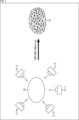
- FIG. 1 is a diagram for explaining an overview of photogrammetry.
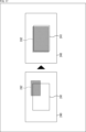
- FIG. 1 is a diagram for explaining an overview of real-time 3D modeling.
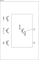
- FIG. 1 illustrates an example of a method for assisting imaging for 3D modeling.
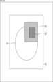
- 11A and 11B are diagrams illustrating an example of imaging control and imaging guidance.
- FIG. 13 is a diagram illustrating an example of overlap.
- 1A to 1C are diagrams illustrating examples of how imaging is performed depending on the distance from a subject.
- FIG. 13 is a diagram illustrating an example of parallel processing.
- FIG. 13 is a diagram illustrating an example of a scoring process.
- FIG. 13 is a diagram illustrating an example of a scoring process.
- FIG. 1 is a diagram illustrating an example of a scoring process.
- FIG. 13 is a diagram illustrating an example of a scoring process.
- FIG. 13 is a diagram illustrating an example of a scoring process.
- FIG. 13 is a diagram illustrating an example of a scoring process.
- FIG. 13 is a diagram showing an example of an output of a scoring result.
- FIG. 13 is a diagram showing an example of output of overlap information.
- FIG. 11 is a diagram showing an example of display of guidance information.
- FIG. 11 is a diagram showing an example of display of guidance information.
- FIG. 11 is a diagram showing an example of display of guidance information.
- FIG. 11 is a diagram showing an example of display of guidance information.
- FIG. 11 is a diagram showing an example of display of guidance information.
- FIG. 11 is a diagram showing an example of display of guidance information.
- FIG. 11 is a diagram showing an example of display of guidance information.
- FIG. 11 is a diagram showing an example of display of guidance information.
- FIG. 11 is a diagram showing an example of display of guidance
- FIG. 11 is a diagram showing an example of display of guidance information.
- FIG. 11 is a diagram showing an example of display of guidance information.
- FIG. 11 is a diagram showing an example of display of guidance information.
- FIG. 11 is a diagram showing an example of display of guidance information.
- FIG. 1 is a diagram showing an example of an outline of a work flow.
- FIG. 13 is a diagram illustrating an example of incremental processing.
- FIG. 13 is a diagram showing a display example.
- FIG. 13 is a diagram showing a display example.
- FIG. 13 is a diagram showing a display example.
- FIG. 13 is a diagram showing a display example.
- FIG. 13 is a diagram showing a display example.
- FIG. 11 is a diagram showing an example of a first 3D modeling state.
- FIG. 11 is a diagram showing an example of a first 3D modeling state.
- FIG. 11 is a diagram showing an example of a second 3D modeling state.
- FIG. 13 is a diagram illustrating an example of a correction process.
- FIG. 13 is a diagram showing an example of a state when imaging work is resumed.
- FIG. 13 is a diagram showing an example of an image capturing operation performed by a plurality of users.
- FIG. 13 is a diagram showing an example of an image capturing operation performed by a plurality of users.
- 1 is a block diagram showing an example of a main configuration of an imaging apparatus;
- 11 is a flowchart illustrating an example of the flow of a 3D modeling process.
- 11 is a flowchart illustrating an example of the flow of a real-time 3D modeling process.
- 11 is a flowchart illustrating an example of the flow of photogrammetry processing.
- FIG. 1 is a diagram illustrating an example of a main configuration of an information processing system.
- 1 is a block diagram showing an example of a main configuration of an imaging communication device;
- 1 is a block diagram showing an example of a main configuration of an imaging apparatus;
- FIG. 2 is a block diagram showing an example of a main configuration of a server.
- 11 is a flowchart illustrating an example of the flow of a 3D modeling process.
- 45 is a flowchart continuing from FIG. 44, illustrating an example of the flow of a 3D modeling process.
- 1 is a block diagram showing an example of a main configuration of an imaging communication device;
- FIG. 2 is a block diagram showing an example of a main configuration of a server.
- 11 is a flowchart illustrating an example of the flow of a 3D modeling process.
- 49 is a flowchart continuing from FIG. 48 illustrating an example of the flow of a 3D modeling process.
- 1 is a block diagram illustrating an example of a main configuration of an information processing system. 1 is a block diagram showing an example of a main configuration of an imaging communication device; FIG. 2 is a block diagram showing an example of a main configuration of a server. 1 is a block diagram showing an example of a main configuration of an information processing device;
- 11 is a flowchart illustrating an example of the flow of a 3D modeling process.
- 13 is a flowchart illustrating an example of the flow of an incremental 3D modeling process.
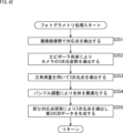
- 11 is a flowchart illustrating an example of the flow of a display control process. 11 is a flowchart illustrating an example of the flow of a coordinate correction process.
- 1 is a block diagram showing an example of a main configuration of an imaging communication device;
- FIG. 2 is a block diagram showing an example of a main configuration of a computer.
- 3D Modeling ⁇ Photogrammetry>
- a method for generating (reconstructing) a model of a three-dimensional shape of an object there has been a method called photogrammetry, in which the 3D object is photographed from multiple directions and 3D data is generated based on the multiple photographed images.
- photogrammetry a method for generating a model of the three-dimensional shape of a 3D object is also referred to as 3D modeling.
- Photogrammetry is a technique for reconstructing a highly accurate three-dimensional model using the principles of triangulation from multiple images taken from various viewpoints.
- "accuracy" in relation to 3D data (3D model) refers not only to the reproducibility (accuracy, definition, etc.) of the three-dimensional shape of the target 3D object, but also to the reproducibility (accuracy, definition, etc.) of the texture applied to the surface of the 3D model.
- cameras 11-1 to 11-5 capture images of a 3D object 10 from multiple viewpoints to obtain multiple captured images. These captured images are then used to perform processes called SfM (Structure from Motion) and MVS (Multi-view Stereo), and further meshing and texturing are performed as post-processing to generate 3D data 15.
- SfM Structure from Motion
- MVS Multi-view Stereo
- corresponding points are searched for between captured images, the position and orientation of the camera are derived using epipolar constraints, and the positions of each corresponding point in three-dimensional space are identified using triangulation based on the camera position and orientation.
- these points in three-dimensional space are also referred to as three-dimensional points.
- three-dimensional points that correspond to each corresponding point are identified. Then, the entire group of three-dimensional points identified in this way is optimized using bundle adjustment.
- the 3D point cloud derived as described above is used to perform a dense corresponding point search and add additional 3D points.
- photogrammetry uses a global optimization calculation called bundle adjustment to minimize error, which allows for very accurate results, but it also imposes a heavy computational load. Also, because it is based on geometric calculations rather than physical measurements, in principle the higher the resolution of the image, the more accurate the model that can be restored.
- ⁇ Real-time 3D modeling> As a 3D modeling method different from such photogrammetry, there is a method called real-time 3D modeling, which generates 3D data instantly (in real time) based on captured images, posture information, depth, and other information.
- a camera 21 captures an image of a 3D object 10 while moving around the periphery of the 3D object 10 as shown by a dotted line 22.
- the camera 21 is equipped with not only an image sensor but also a Lidar (Light Detection And Ranging) scanner (dToF (Direct Time of Flight) module), which obtains captured images and detects depth (distance to the subject).
- dToF Direct Time of Flight
- the camera 21 is equipped with an inertial sensor that detects the acceleration and angular velocity of the camera 21 (also referred to as inertial information in this specification).
- SLAM Simultaneous Localization and Mapping
- TSDF Transaction Signed Distance Function
- 3D data 25 mesh and texture
- MC Marching Cubes
- SLAM position and orientation of the camera are estimated based on the captured image and inertial information (self-localization).
- depth is associated with voxels to detect volume.
- MC an isosurface is calculated using adjacent voxels.
- real-time orientation information from SLAM the volume of a voxel can be detected (without going through a point cloud) by overlaying the depth (how far the light ray has reached) from multiple frames.
- Using a voxel representation makes it possible to estimate viewpoints that are in shadow and that need to be photographed (missing viewpoints). This makes it possible to detect the hole and protrusion structures of a 3D object.
- Neural Rendering e.g., NeRF (Neural Radiance Fields)
- NeRF Neral Radiance Fields
- Figure 3 compares the characteristics of photogrammetry and real-time 3D modeling. As shown in Figure 3, when comparing the methods, photogrammetry uses SfM (including self-localization) and MVS, while real-time 3D modeling uses self-localization (SLAM) and TSDF. When comparing the data used, photogrammetry uses only image data, while real-time 3D modeling uses depth and orientation data in addition to image data. When comparing the processing time, photogrammetry requires a long time, from several minutes to several tens of hours, while real-time 3D modeling allows for nearly instantaneous (real-time) processing at 30 fps (frame/sec).
- photogrammetry requires computing power at the level of a high-end CPU (Central Processing Unit) and GPU (Graphics Processing Unit), while real-time 3D modeling requires computing power at the level of a mobile AP (Application Processor).
- CPU Central Processing Unit
- GPU Graphics Processing Unit
- real-time 3D modeling requires computing power at the level of a mobile AP (Application Processor).
- photogrammetry is relatively high-resolution, depending on the resolution, number, and shooting method of the captured images
- real-time 3D modeling is relatively low-resolution, depending on the depth and self-location estimation accuracy, etc.
- the internal representation of the generated 3D data is point cloud-based in photogrammetry, whereas it is voxel-based in real-time 3D modeling.
- subject size or resolution there are no restrictions on subject size or resolution in photogrammetry, but real-time 3D modeling depends on the sensor.
- photogrammetry is relatively high since it is optimized by bundle adjustment, whereas real-time 3D modeling is relatively low, depending on the sensor and self-localization accuracy.
- photogrammetry is indefinite (size is unknown), whereas real-time 3D modeling is unique (absolute size is known).
- the differences in characteristics between photogrammetry and real-time 3D modeling are as shown below.
- applying real-time 3D modeling can reduce the amount of work and processing required for 3D modeling compared to applying photogrammetry or Neural Rendering.
- applying photogrammetry or Neural Rendering can generate more accurate 3D data than applying real-time 3D modeling.
- ⁇ Easy 3D modeling> For example, to obtain more accurate 3D data, photogrammetry or neural rendering can be applied as described above. However, even in that case, it is desirable to reduce the workload and processing volume of 3D modeling. In order to reduce the workload and processing volume of 3D modeling, it is necessary to generate 3D data with as few images as possible and as high accuracy as possible.
- Imaging control Image capture control based on scoring results> Therefore, 3D modeling is performed twice, and the results of the first 3D modeling are used to control the imaging for the second 3D modeling.
- a second imaging is performed to capture an image of a 3D object having a three-dimensional shape
- a second 3D modeling process is performed to generate second 3D data (second three-dimensional shape information) expressing the three-dimensional shape of the 3D object using the second captured image obtained by the second imaging (second 3D data generation process 104 in FIG. 4).
- the second imaging is controlled so that the second imaging for the second 3D modeling process can be performed at a more appropriate position and orientation (second 3D modeling imaging control process 103 in FIG. 4).
- the first 3D data generation process 101 and scoring process 102 in FIG. 4 are executed.
- the first 3D data generation process 101 is a process for generating first 3D data (first three-dimensional shape information) that represents the three-dimensional shape of a 3D object. That is, the first 3D data generation process 101 involves a first imaging process for imaging a 3D object, and a first 3D modeling process for generating first 3D data using the first captured image obtained by the first imaging process.
- the scoring process 102 is a process for evaluating (scoring) the accuracy of second 3D data that can be generated using the second captured images generated by the second imaging performed so far. This scoring is performed based on the first 3D data generated by the first 3D modeling process. In the second 3D modeling imaging control process 103, the second imaging is controlled based on the scoring result.
- the accuracy of the second 3D data that can be generated based on the second captured image obtained by the second imaging up to the present time is evaluated (scoring is performed). In this way, the scoring result can be generated more easily.
- the second imaging is controlled based on the scoring result. In this way, the second imaging can be controlled so that it is performed at a more appropriate position and orientation. In other words, the second 3D modeling process can be executed using the second captured image captured at a more appropriate position and orientation. Therefore, it is possible to generate 3D data with higher accuracy while suppressing an increase in the load (workload and processing volume) of 3D modeling. In other words, 3D modeling can be performed more easily.
- a captured image refers to a general image obtained by an image sensor or the like.
- an imaging device or the like generally obtains the following images.
- a still image is obtained by an image sensor or the like at the timing when a shutter button or the like is operated, and is stored in a storage medium or the like as an imaging result.
- acquisition of a moving image is started by an image sensor or the like from the timing when a shutter button or the like is operated, and the moving image is stored in a storage medium or the like as an imaging result.
- an image (sometimes called a captured image) is obtained by an image sensor or the like before a shutter button or the like is operated, and is not stored in a storage medium as an imaging result, but is used for display on a monitor or the like.
- a captured image refers to these images.
- a captured image may be a still image or a moving image.
- a captured image may or may not be stored in a storage medium or the like as an imaging result.
- a captured image may or may not be displayed on a monitor or the like.
- a captured image may be obtained before a shutter button or the like is operated, may be obtained at the timing of operation, or may be obtained after operation.
- the captured image may be the data itself (so-called RAW data) obtained by an image sensor or the like.
- the captured image may be an image that has been subjected to color separation processing or color conversion processing.
- the captured image may be an image that has been subjected to signal processing such as defect correction, noise reduction, AWB (Automatic White Balance), or gamma correction.
- the captured image may be an image that has been subjected to other image processing.
- an imaging section (image sensor) that performs the first imaging is also referred to as a first imaging section
- an imaging section (image sensor) that performs the second imaging is also referred to as a second imaging section.
- the first imaging is performed in the first 3D data generation process 101. That is, the first captured image is generated by the first imaging unit.
- the distance (depth) from the first imaging unit to the subject (3D object) included in the first captured image may be detected by a depth sensor. Any method may be used to detect the depth by the depth sensor.
- the depth sensor may be integrated with the first imaging unit, or may be a sensor different from the first imaging unit and provided at a different position from the first imaging unit. In the following, unless otherwise specified, it is assumed that the depth is appropriately calibrated for the first captured image.
- the inertial information (angular velocity and acceleration) of the first imaging unit may be detected by an inertial information sensor. Any method may be used to detect the inertial information by the inertial information sensor.
- the inertial information sensor may be integrated with the first imaging unit, or may be a sensor different from the first imaging unit and provided at a different position from the first imaging unit.
- the generated first captured image is used in the first 3D data generation process.
- depth and inertial information are also used in the first 3D data generation process.
- the number of first imaging units (image sensors), depth sensors, and inertial information sensors may be any number, and may be singular or plural. In other words, the number of first imaging units, depth sensors, and inertial information sensors may all be the same, or two of them may be the same, or they may be different from each other.
- first 3D modeling process is performed in the first 3D data generation process 101.
- first 3D data (first three-dimensional shape information) expressing the three-dimensional shape of a 3D object is generated based on a first captured image generated by a first capture of the 3D object.
- This first 3D data may have less information and lower accuracy than the second 3D data (second three-dimensional shape information) generated by the second 3D data generation process 104.
- any method may be used for this first 3D modeling process.
- orientation information corresponding to the angle of view of the first captured image may be derived, and the first 3D data may be generated based on the orientation information, the first captured image, and the depth of the subject (3D object) in the first captured image.
- the first 3D data may be generated by updating the TSDF and performing MC based on that information.
- this orientation information is information that indicates the position and orientation of the first imaging unit in three-dimensional space. Any method may be used to derive this orientation information.
- the orientation information may be derived based on inertial information (acceleration and angular velocity) of the first imaging unit. For example, SLAM may be applied.
- the above-mentioned real-time 3D modeling may be applied as the first 3D modeling process.
- the first 3D modeling process can be performed instantly (in real time), and the first 3D data can be obtained instantly (in real time). Therefore, the imaging control process for the second 3D modeling can be performed instantly (in real time). In other words, 3D modeling can be performed more easily.
- the attitude information of the first imaging unit and the first 3D data may be generated using a neural network that receives the first captured image, inertial information of the first imaging unit, and depth as inputs.
- the first 3D data may be any data that represents the three-dimensional shape of a 3D object, and may be, for example, a point cloud, or may include a mesh that represents the three-dimensional shape of the 3D object through vertices and connections, and a texture that is applied to the surface of the mesh. This first 3D data is supplied to the scoring process 102.
- the accuracy of the second 3D data that can be generated using the second captured image generated by the second imaging performed so far is evaluated.
- This scoring is performed based on the first 3D data generated by the first 3D modeling process and the position and orientation of the second imaging performed so far. That is, the first 3D data is regarded as a 3D object modeled in the second 3D modeling process, and a score is calculated for each local part of the first 3D data.
- the first 3D data includes a mesh that indicates the three-dimensional shape of the 3D object by vertices and connections, and a texture applied to the surface of the mesh
- a scoring result is generated for each polygon of the mesh. That is, a part of the first 3D data from which a higher accuracy of the second 3D data can be obtained is evaluated higher (set to a higher score).
- the scoring process 102 evaluates the upper side of the first 3D data 120 in the figure as having a relatively high score, and the lower side of the first 3D data 120 in the figure (gray part) as having a relatively low score. An example of the scoring method will be described later.
- the number of types of scores may be any number.
- the scores may be classified into three levels (e.g., low score, medium score, high score), 10 levels (e.g., 0 to 9 points), 100 levels (e.g., 0 to 99 points), or any other number of levels.
- the scoring results generated by the scoring process 102 are supplied to the second 3D modeling imaging control process 103.
- the second imaging is controlled based on the position and orientation of the second imaging unit and the scoring result obtained by the scoring process 102.
- the second imaging is controlled so as to be performed at a position and orientation that will improve the scoring result.
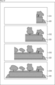
- the scoring process 102 produces a scoring result such as that shown in FIG. 5. From this scoring result, it is clear that there is insufficient imaging of the lower part of the 3D object corresponding to the first 3D data 120 (e.g., the gray part).
- the second imaging is controlled to capture an image from the lower side of the 3D object in the drawing, so that an image of the gray portion where imaging is lacking can be obtained.
- the position and orientation of camera 121-4 is determined to be more appropriate as the position and orientation for capturing the second image, and the second imaging is controlled to capture the image at the position and orientation of camera 121-4.
- the second 3D modeling imaging control process 103 may specify a position and orientation (range) that can improve the score of the portion (gray portion) where the second imaging is lacking based on the scoring result.
- the current orientation information (position and orientation) of the second imaging unit may be provided to the scoring process 102 as imaging viewpoint information, and a scoring result may be obtained when a second imaging image obtained at the current position and orientation is added. If the score is higher than the score before the second imaging image is added by a predetermined threshold or more, it may be determined that the current position and orientation are the position and orientation at which the second imaging should be performed.
- the orientation information of the first imaging unit may be provided to the scoring process 102 as imaging viewpoint information instead of the orientation information of the second imaging unit.
- the orientation information of the first imaging unit may be used to derive the orientation information of the second imaging unit, and the scoring result may be generated using the orientation information of the second imaging unit.
- the scoring result may be generated using a neural network that includes the orientation information of the first imaging unit as an input parameter.
- the second 3D modeling imaging control process 103 it may be determined whether or not the position and orientation at which the second imaging should be performed are appropriate, based on the overlap rate with the imaging range of the second imaging performed so far.
- the overlap rate indicates the degree (proportion) of the area where the imaging ranges overlap (overlap area). In other words, it may be determined whether or not the position and orientation of the second imaging are more appropriate, depending on the extent to which the imaging range of the second imaging to be performed overlaps with the area reflected in the second imaging images obtained so far.
- the position and orientation at which a second captured image is obtained that has an overlap rate that makes it easier to perform the second 3D modeling process (allows for more accurate 3D modeling) may be determined to be a more appropriate position and orientation (position and orientation at which the second image should be captured).
- the overlap rate at which the second 3D modeling process is easier to perform also depends on the three-dimensional shape of the 3D object.
- the subject in the case of shooting from a so-called drone, the subject can be considered as a plane 130 as shown on the left in FIG. 6.
- the imaging range when the plane 130 is imaged from the camera 131-1 is the range indicated by the double arrow 132-1.
- the imaging range when the plane 130 is imaged from the camera 131-2 is the range indicated by the double arrow 132-2. Therefore, the overlap area of these captured images is the range indicated by the double arrow 133.
- the way in which the captured images overlap is simple, if an overlap rate of a certain percentage or more is obtained, more accurate 3D modeling process can be performed.
- the subject is a 3D object (first 3D data 135)
- the overlap is three-dimensional, as shown in the second captured image 136-1 and the second captured image 136-2 in the example on the right of FIG. 6. Therefore, the overlap rate required to perform sufficiently accurate 3D modeling processing depends on the three-dimensional shape of the 3D object, etc. Therefore, when considering the overlap rate for the second captured images obtained so far when determining the position and orientation for the second imaging, it is desirable to also consider the three-dimensional shape of the 3D object (first 3D data), etc. (the position and orientation for the second imaging can be determined more accurately).
- the distance of the image capture position from the subject (3D object) may be controlled. In other words, not only the angle from which part of the 3D object is captured, but also the distance from which that part is captured may be controlled.
- the appropriate distance from the 3D object as the position for the second imaging depends on the three-dimensional shape of the 3D object. Therefore, in the second 3D modeling imaging control process 103, the distance from the 3D object (subject) of the position for the second imaging may be controlled according to the three-dimensional shape (complexity) of the 3D object. By doing so, as described above, it is possible to suppress an unnecessary increase in the number of times the second imaging is performed while suppressing a decrease in the accuracy of the second 3D modeling process (the accuracy of the second 3D data). In other words, it is possible to control so that the second imaging is performed at a more appropriate position and orientation.
- any method may be used to derive the complexity of the three-dimensional shape of the 3D object.
- this complexity may be derived based on the first 3D data.
- the first 3D data may be processed as a two-dimensional image, and the complexity of the three-dimensional shape of the 3D object may be derived from the pattern, etc. of the two-dimensional image. By doing so, it is possible to suppress an increase in the processing load related to the derivation of the complexity of the three-dimensional shape of the 3D object.
- a detection frame may be provided, and the complexity of the three-dimensional shape of the 3D object may be derived within the detection frame.
- This detection frame may be of any shape or size. For example, within this detection frame, the number of polygons of the first 3D data that face the imaging surface of the second image may be found, the degree of variation in the normal direction within the detection frame may be quantified, and the complexity of the three-dimensional shape of the 3D object within the detection frame may be derived based on the degree of variation. In general, the greater the variation, the more complex the shape, and if they face the same direction, they can be considered to be closer to a planar shape. Also, the average of the normal directions of each polygon within the detection frame may be used as a representative value of the degree of facing the imaging surface, and the complexity of the three-dimensional shape of the 3D object may be derived based on this representative value.
- the complexity of the three-dimensional shape of the 3D object may be determined to be low.
- the complexity of the three-dimensional shape of a 3D object may be any parameter (value based on it) as long as it is a quantitative value that can be used to estimate the direction, frequency, and distance at which imaging is required based on the general shape of a subject in a certain area.
- any method may be used to control the distance from the 3D object of the second imaging based on the complexity of the 3D object's three-dimensional shape. For example, the more complex the three-dimensional shape of the 3D object, the closer the second imaging may be to a position from the 3D object. Furthermore, the simpler the three-dimensional shape of the 3D object, the farther the second imaging may be to a position from the 3D object.
- the position and orientation (more appropriate position and orientation) at which the second imaging should be performed is determined, and control information (imaging control information) is generated to control the second imaging to be performed at that position and orientation. Then, that imaging control information is supplied to the second 3D data generation process 104. For example, when a user or the like moves the second imaging unit and the position and orientation of the second imaging unit match the determined "position and orientation at which the second imaging should be performed," imaging control information instructing the second imaging is generated and supplied to the second 3D data generation process 104 (i.e., the second imaging is performed at the "position and orientation at which the second imaging should be performed").
- the second imaging unit performs the second imaging according to the control of the second 3D modeling imaging control process 103 to generate a second captured image.
- the second imaging unit may perform the second imaging based on the imaging control information generated in the second 3D modeling imaging control process 103.
- the second imaging unit may perform the second imaging when imaging is instructed by the imaging control information (at the timing when imaging is instructed).
- the control unit that controls the position and attitude of the second imaging unit may move the second imaging unit to a position specified by the imaging control information, set the second imaging unit to the attitude specified by the imaging control information, and the second imaging unit may perform the second imaging at that position and attitude.
- the number of second imaging units may be any number, and may be either singular or plural. Furthermore, the first imaging unit and the second imaging unit may be a common imaging unit (the same imaging unit) or may be different imaging units provided at different positions.
- the specifications of the second imaging unit may be the same as or different from the specifications of the first imaging unit.
- the second captured image may have a higher image quality than the first captured image.
- the second captured image may have a higher resolution than the first captured image.
- the second captured image may have a higher dynamic range than the first captured image.
- the method of the second 3D modeling process executed in the second 3D data generation process 104 may be any method.
- the method of the second 3D modeling process may be the same as or different from the method of the first 3D modeling process.
- the above-mentioned photogrammetry may be applied as the second 3D modeling process. That is, in the second 3D modeling process, SfM and MVS may be applied, and a point cloud may be generated from a plurality of second captured images. Furthermore, second 3D data may be generated by performing meshing and texturing on the point cloud as post-processing. That is, the second 3D data may be any data that expresses the three-dimensional shape of a 3D object, and may be, for example, a point cloud, or may include a mesh that indicates the three-dimensional shape of a 3D object through vertices and connections, and a texture that is applied to the surface of the mesh. Furthermore, the above-mentioned Neural Rendering may be applied as the second 3D modeling process.
- the second 3D data may be generated using, in addition to the second captured image, orientation information of the second imaging unit that performs the second image capture (orientation information corresponding to the angle of view of the second captured image obtained so far).
- This orientation information is information that indicates the position and orientation of the second imaging unit in three-dimensional space.
- the second 3D data may be generated using orientation information (position and orientation in three-dimensional space) of the first imaging unit.
- the second 3D data may be generated using orientation information derived in the first 3D modeling process.
- the orientation information of the second imaging unit may be derived using the orientation information of the first imaging unit
- the second 3D data may be generated using the orientation information of the second imaging unit.
- the second 3D data may be generated using a neural network that receives the orientation information of the first imaging unit and the second captured image as input.
- the second 3D data may be encoded.
- This encoding method may be any method.
- the second imaging may be performed (for example, manually) without being based on the imaging control information.
- such an imaging method is also referred to as manual imaging.
- imaging timing information indicating the imaging timing is generated in (the second imaging of) the second 3D data generation process 104 and supplied to the second 3D modeling imaging control process 103.
- orientation information of the second imaging unit at the imaging timing is obtained, and the orientation information of the second imaging unit at the imaging timing is supplied to the scoring process 102 as imaging viewpoint information.
- the scoring process 102 a score is calculated based on the imaging viewpoint information.
- the second captured image obtained by manual imaging orientation information of the second imaging unit corresponding to the angle of view
- camera information regarding the second imaging unit may be generated and supplied to the scoring process 102. Then, in the scoring process 102, scoring may be performed based on this camera information, and a scoring result may be generated.
- This camera information may include any information.
- the camera information may include internal parameters of the imaging unit.
- the camera information may also include external parameters of the imaging unit.
- the camera information may also include a captured image.
- the camera information may also include angle of view information (focal length information) of the second captured image.
- the camera information may also include distortion correction information.
- the camera information may also include shading correction information.
- the camera information may also include breathing correction information.
- the camera information may also include focus position information.
- the camera information may also include image plane phase difference information. In other words, these pieces of information may be used for scoring (evaluation of the accuracy of the second three-dimensional shape information that can be generated).
- first 3D data generation process 101 first imaging and first 3D modeling process
- scoring process 102 scoring process
- second imaging control process for 3D modeling 103 in FIG. 4 may be executed in parallel with each other.
- the first 3D data of the part of the 3D object that is the subject where the first image was captured may be generated sequentially.
- 3D data can be generated instantly (in real time) based on the captured image and depth information, etc. That is, in this case, the first 3D modeling can be performed while the first image is being captured (while the first captured image is being obtained), and the first 3D data can be generated.
- the camera is moved around the 3D object that is the subject, and images of each part of the 3D object are captured, but before an image of the entire 3D object is obtained, 3D modeling can be performed based on the captured image and depth that have been obtained. That is, 3D data of the part where the image was captured can be generated sequentially.
- the scoring process 102 the first 3D data corresponding to a part of the 3D object may be scored (evaluation of the accuracy of the second three-dimensional shape information that can be generated using the second captured image generated by the second imaging performed so far).
- the scoring process 102 can be started before the first 3D data generation process 101 is completed (before the first 3D data of the entire 3D object is generated).
- the first 3D data generation process 101 and the scoring process 102 can be executed in parallel.
- the second imaging may be controlled based on the obtained scoring result (the scoring result for the first 3D data corresponding to a part of the 3D object).
- the second 3D modeling imaging control process 103 can be started before the scoring process 102 ends (before the scoring result for the entire 3D object is obtained).
- the scoring process 102 and the second 3D modeling imaging control process 103 can be executed in parallel.
- the first 3D data generation process 101, the scoring process 102, and the second 3D modeling imaging control process 103 can be executed in parallel with each other.
- the time axis runs from left to right as indicated by the arrow.
- first 3D data for the portion where the first imaging was performed, such as first 3D data 151-1, first 3D data 151-2, and first 3D data 151-3.
- first 3D data generation process first 3D modeling process
- scoring process 102 it is possible to sequentially derive scoring results for the portion where the first 3D data was generated, such as scoring result 152-1, scoring result 152-2, and scoring result 152-3.
- the scoring process 102 and the second 3D modeling imaging control process 103 in parallel, the second imaging can be controlled at each timing based on the scoring results obtained so far (scoring result 152-1, scoring result 152-2, scoring result 152-3).
- the first 3D data generation process 101, the scoring process 102, and the second 3D modeling imaging control process 103 in parallel with each other, it is possible to control the second imaging while performing the first imaging.
- the first imaging and the second imaging can be performed in parallel (instantaneously).
- Conditions for photogrammetry to work well include, for example, that SfM works well, that MVS works well, and that texturing (texture mapping) works well.
- Conditions for SfM to work well include, for example, that a baseline can be secured and that feature points can be matched.
- a condition for MVS to work well includes, for example, that a baseline can be secured.
- Conditions for texturing to work well include, for example, that a high-definition texture can be obtained in the captured image and that the surface to which the texture is applied is photographed as directly in front as possible.
- the baseline refers to the distance between the imaging viewpoint positions (the camera positions during imaging).
- Scoring polygons Conditions for whether a polygon surface can be restored using SfM or MVS include, for example, minimum visibility conditions (whether the polygon is visible from the imaging position), favorable accuracy conditions (conditions that improve accuracy), and favorable matching (detection of corresponding points) conditions (conditions that make matching easier).
- Minimum conditions for visibility include, for example, that the center of gravity of the target polygon is within the field of view (within the imaging angle) when viewed from the viewpoint (imaging position), that the dot product of the target polygon's normal and the line of sight (vector pointing from the line of sight to the center of gravity of the target polygon) is at least positive, that there are no other polygons blocking the line of sight, and that there are two or more lines of sight from which the target polygon can be seen (visible).
- line of sight 162 pointing from a certain viewpoint toward the center of gravity of the target polygon 160, so the target polygon 160 is located within that field of view.
- the dot product of the line of sight 162 and the normal 161 of the target polygon 160 is positive.
- line of sight 162 reaches the target polygon 160 without being blocked by other polygons, and is therefore a "line of sight through which the target polygon 160 is visible.” Therefore, line of sight 162 meets the minimum visibility conditions.
- line of sight 163 is blocked by polygon 164, so it is not a "line of sight through which target polygon 160 can be seen.”
- favorable conditions for accuracy include, for example, a sufficiently long baseline, a sufficiently large ratio of the baseline length to the distance to the subject (baseline length/distance to subject), and a sufficiently large number of visible viewpoints with a large variance in the angles they make with each other.
- conditions for improved accuracy include a sufficiently long baseline 173 between viewpoints 171 and 172 from which the target polygon 170 is visible (viewpoints 171 and 172 are sufficiently far apart), and a sufficiently large ratio of the length of baseline 173 to distance 174 to the subject (the value of "baseline length/distance to subject" is sufficiently large).
- the target polygon 180 is visible from two viewpoints, viewpoint 181 and viewpoint 182.
- the target polygon 180 is visible from six viewpoints, viewpoint 181 to viewpoint 186.
- the example on the right has more visible viewpoints and a greater variance in the angles they form than the example on the left. With more visible points, triangulation can be performed more robustly from multiple different pieces of information, which is expected to improve accuracy. Therefore, the example on the right meets the conditions for improved accuracy more than the example on the left.
- favorable conditions for matching include, for example, a sufficiently small angle between the normal of the target polygon and the line of sight from the viewpoint toward the center of gravity of the target polygon, a sufficiently small ratio of the distance between the paired viewpoint and the subject, and the existence of a texture that can be matched.
- the angle between the normal 191 of the target polygon 190 and the viewpoint 192 is smaller than the angle between the normal 191 and the viewpoint 193. Therefore, it is easier to correctly detect the feature points of the surface of the target polygon 190 from the viewpoint 192 than from the viewpoint 193. Also, in the example on the right side of FIG. 12, the distance from the viewpoint 194 to the subject (target polygon 190) is significantly farther than the distance from the viewpoint 195 to the subject (target polygon 190). In other words, the ratio of the distance to the subject is large between the viewpoints 194 and 195.
- Conditions for determining whether a certain polygon surface has a sufficient viewpoint for texturing include, for example, a minimum condition (whether it is visible or not) and a favorable condition for texturing (a condition that allows for more beautiful texturing).
- Minimum conditions include, for example, the existence of a viewpoint that satisfies the minimum visibility conditions mentioned above.
- favorable conditions for texturing include, for example, a small angle between the normal of the target polygon and the line of sight from the viewpoint toward the center of gravity of the target polygon, and sufficient resolution being obtained when the distance from the viewpoint to the subject is below a certain level.
- any conditions may be applied in scoring.
- the contents of the conditions may be of any nature.
- the above conditions may be omitted, or conditions other than the above conditions may be added.
- Scoring of the second captured image obtained by the second imaging may be performed.
- the second captured image may be scored based on camera information.
- the second captured image may be evaluated as to whether or not it is focused at a desired position. It may also be evaluated as to whether or not there is camera shake. It may also be evaluated as to whether or not the exposure is appropriate. It may also be evaluated as to whether or not it is easy to capture feature points.
- ⁇ Example of scoring calculation> For example, as shown in Fig. 13, the distance between the target captured image 201 and the target polygon 202 is d. The ideal distance to the subject is d opt . Furthermore, c d is a predetermined coefficient. In this case, the score s d may be derived as shown in the following formula (1).
- the center of the target polygon 202 is defined as c p .
- the line of sight from the target captured image 201 to the center c p is defined as v p .
- the normal of the target polygon 202 is defined as n p .
- the angle between the line of sight v p and the normal n p is defined as ⁇ .
- the angle ⁇ can be derived as shown in the following formula (2).
- a score s ⁇ based on the angle ⁇ may be derived as shown in the following formula (3).
- c ⁇ is a predetermined coefficient.
- the optical axis of the camera (the normal vector of the target captured image 201 starting from the center of the target captured image 201) is denoted by vc .
- the angle between this optical axis vc and the line of sight vp is denoted by ⁇ .
- the angle ⁇ can be derived as shown in the following formula (4).
- a score s ⁇ based on the angle ⁇ may be derived as shown in the following formula (5).
- c ⁇ is a predetermined coefficient.
- a total score s total may be derived as shown in the following formula (6).
- the weighted sum of the total scores of the top two viewpoints may be used as the final score.
- calculation method is just one example. Any calculation method may be used in the scoring process 102 and is not limited to this example.
- Example of configuration for executing processing> 4 may be executed by any device.
- the first 3D modeling process of the first 3D data generation process 101, the scoring process 102, and the second 3D modeling imaging control process 103 may be executed in an information processing device.
- the information processing device may include a first 3D modeling processing unit that generates first three-dimensional shape information expressing the three-dimensional shape of a 3D object based on a first captured image generated by a first imaging of the 3D object, a scoring processing unit that uses the first three-dimensional shape information to evaluate the accuracy of second three-dimensional shape information that can be generated using a second captured image generated by a second imaging performed so far, and generates a scoring result, and an imaging control unit that controls the second imaging of the 3D object based on the scoring result.
- this information processing device is also referred to as a first information processing device.
- first three-dimensional shape information expressing the three-dimensional shape of a 3D object is generated based on a first captured image generated by a first capture of the 3D object, the first three-dimensional shape information is used to evaluate the accuracy of second three-dimensional shape information that can be generated using a second captured image generated by a second capture performed so far, a scoring result is generated, and a second capture of the 3D object is controlled based on the scoring result.
- the first 3D modeling processing unit may also include an orientation information generation unit that generates orientation information indicating the position and orientation of the first imaging unit based on the first captured image and the acceleration and angular velocity of the first imaging unit, and a three-dimensional shape generation unit that generates first three-dimensional shape information of the 3D object based on the orientation information and the depth of the 3D object.
- an orientation information generation unit that generates orientation information indicating the position and orientation of the first imaging unit based on the first captured image and the acceleration and angular velocity of the first imaging unit
- a three-dimensional shape generation unit that generates first three-dimensional shape information of the 3D object based on the orientation information and the depth of the 3D object.
- the first imaging of the first 3D data generation process 101 described above may be performed.
- the first information processing device may further include a first imaging unit.
- the first information processing device including the first imaging unit may include a depth detection unit that detects depth, or an inertial measurement unit that detects the acceleration and angular velocity of the first imaging unit, or may include both.
- the second imaging of the second 3D data generation process 104 described above may be performed.
- the first information processing device may further include a second imaging unit.
- the second captured image generated by this second imaging may be encoded.
- a first information processing device including a second imaging unit may include an encoding unit that encodes the second captured image generated by the second imaging unit.
- This encoded second captured image may be supplied to another information processing device via communication, or may be stored in a storage medium.
- the second 3D modeling process of the second 3D data generation process 104 described above may be further performed.
- the first information processing device having a second imaging unit may further include a second 3D modeling processing unit that generates second three-dimensional shape information based on the second captured image generated by the second imaging unit.
- the second 3D modeling processing unit may include a corresponding point position derivation unit that derives three-dimensional positions of corresponding points between a plurality of second captured images, and a three-dimensional point addition unit that adds three-dimensional points based on the three-dimensional positions of the corresponding points.
- meshing and texturing may be further performed as post-processing.
- the second three-dimensional shape information may include a mesh that indicates the three-dimensional shape of the 3D object by vertices and connections, and a texture that is applied to the surface of the mesh.
- the second 3D data generated by this second 3D modeling process may be encoded.
- a first information processing device including a second imaging unit and a second 3D modeling processing unit may further include an encoding unit that encodes the second three-dimensional shape information generated by the second 3D modeling processing unit.
- This encoded second three-dimensional shape information (second 3D data) may be supplied to another information processing device via communication, or may be stored in a storage medium.
- the second imaging of the second 3D data generation process 104 described above may be performed in a second information processing device different from the first information processing device.
- the first information processing device may include a communication unit that communicates with a second information processing device (imaging device) that includes a second imaging unit, the imaging control unit may generate imaging control information that controls the second imaging, and the communication unit may supply the imaging control information to the second information processing device.
- imaging device imaging device
- the imaging control unit may generate imaging control information that controls the second imaging
- the communication unit may supply the imaging control information to the second information processing device.
- the first information processing device may acquire the second captured image generated in the second information processing device.
- the first information processing device having a communication unit may acquire the second captured image supplied from the second information processing device.
- This second captured image may be encoded.
- the first information processing device having a communication unit may have an encoding unit that encodes the second captured image acquired by the communication unit. This encoded second captured image may be supplied to another information processing device by communication, or may be stored in a storage medium.
- the first information processing device may further perform the second 3D modeling process of the second 3D data generation process 104 described above.
- the first information processing device having a communication unit may further include a second 3D modeling processing unit that generates second three-dimensional shape information based on the second captured image acquired by the communication unit.
- the second 3D modeling processing unit may include a corresponding point position derivation unit that derives three-dimensional positions of corresponding points between a plurality of second captured images, and a three-dimensional point addition unit that adds three-dimensional points based on the three-dimensional positions of the corresponding points.
- meshing and texturing may further be performed as post-processing.
- the second three-dimensional shape information may include a mesh that indicates the three-dimensional shape of the 3D object by vertices and connections, and a texture that is applied to the surface of the mesh.
- the second 3D data generated by this second 3D modeling process may be supplied to another information processing device via communication, or may be stored in a storage medium. Furthermore, this second 3D data may be encoded.
- a first information processing device having a communication unit and a second 3D modeling processing unit may further have an encoding unit that encodes the second three-dimensional shape information generated by the second 3D modeling processing unit. Then, the encoded data of the generated second three-dimensional shape information (second 3D data) may be supplied to another information processing device via communication, or may be stored in a storage medium.
- the second image can be captured manually.
- the second captured image obtained by the manual image capture may be used in the second 3D modeling process.
- the scoring process 102 as described above, the accuracy of the second three-dimensional shape information that can be generated using the second captured image obtained so far is evaluated.
- the second captured image obtained by manual image capture may be included in the second captured image.
- the orientation information of the manual image capture may be reflected in the scoring process 102.
- the scoring processing unit of the first information processing device may generate a scoring result based on the position and orientation of the second information processing device corresponding to the timing of the second image capture indicated by the imaging timing information indicating the timing of the second image capture not based on the imaging control information.
- the imaging control unit may obtain the orientation information of the second imaging unit at the imaging timing based on the imaging timing information, and the scoring processing unit may calculate the score based on the orientation information. In this way, the orientation information of the manual image capture is reflected in the scoring result.
- the second imaging may be performed in the first information processing device, or in the second information processing device.
- the first information processing device has a second imaging unit, for example, the second imaging unit may generate imaging timing information indicating the timing when manual imaging is performed and supply it to the imaging control unit.
- the communication unit may obtain imaging timing information supplied from the second information processing device and supply it to the imaging control unit.
- camera information related to the second imaging unit may be reflected in the scoring process 102.
- the scoring processing unit of the first information processing device may generate a scoring result based on the camera information.
- the second imaging may be performed in the first information processing device or in the second information processing device. If the first information processing device has a second imaging unit, for example, the second imaging unit may generate camera information and supply it to the scoring processing unit. Also, if the first information processing device has a communication unit, for example, the communication unit may obtain camera information supplied from the second information processing device and supply it to the scoring processing unit.
- the second information processing device may perform the second imaging of the second 3D data generation process 104 described above.
- the second information processing device may include a second imaging unit and a communication unit that communicates with the first information processing device, the communication unit may acquire imaging control information supplied from the first information processing device, and the second imaging unit may capture a 3D object based on the imaging control information to generate a second captured image.
- This imaging control information is information that controls the second imaging, which is generated based on a scoring result derived based on the first 3D data.
- imaging control information supplied from a first information processing device may be acquired, a second imaging operation may be performed based on the imaging control information, and a second captured image may be generated for generating second 3D data.
- the generated second captured image may be supplied to the first information processing device.
- the communication unit may supply the second captured image generated by the second imaging unit to the first information processing device.
- This second captured image is an image for generating three-dimensional shape information expressing the three-dimensional shape of a 3D object.
- the second captured image may be encoded.
- the second information processing device may include an encoding unit that encodes the second captured image generated by the second imaging unit.
- the communication unit may supply encoded data of the second captured image generated by the encoding unit to the first information processing device. Note that the second captured image (or the encoded data of the second captured image) may be supplied to an information processing device other than the first information processing device.
- the communication unit may supply the second captured image (or the encoded data of the second captured image) to another information processing device.
- this second captured image (or the encoded data of the second captured image) may be stored in a storage medium.
- the second information processing device may include a storage unit that stores the encoded data of the second captured image generated by the encoding unit.
- the second information processing device may also perform the second 3D modeling process described above. That is, in the second information processing device, the second 3D modeling process may be performed using the second captured image generated by the second imaging, and the second 3D data may be generated.
- the second information processing device may further include a second 3D modeling processing unit that generates second three-dimensional shape information (second 3D data) expressing the three-dimensional shape of the 3D object based on the second captured image generated by the second imaging unit.
- the second 3D modeling processing unit may include a corresponding point position derivation unit that derives the three-dimensional positions of corresponding points between the multiple second captured images, and a three-dimensional point addition unit that adds three-dimensional points based on the three-dimensional positions of the corresponding points.
- the second three-dimensional shape information may include a mesh that indicates the three-dimensional shape of the 3D object by vertices and connections, and a texture that is applied to the surface of the mesh.
- the second 3D data generated by this second 3D modeling process may be supplied to another information processing device via communication, or may be stored in a storage medium. Furthermore, this second 3D data may be encoded.
- a second information processing device including a second 3D modeling processing unit may further include an encoding unit that encodes the second three-dimensional shape information generated by the second 3D modeling processing unit. Then, the encoded data of the generated second three-dimensional shape information (second 3D data) may be supplied to another information processing device via communication, or may be stored in a storage medium.
- the second image can be captured manually.
- the second captured image obtained by the manual capture may be used in the second 3D modeling process.
- the scoring process 102 as described above, the accuracy of the second three-dimensional shape information that can be generated using the second captured images obtained so far is evaluated.
- the second captured images may include the second captured images obtained by manual capture. In other words, the posture information of the manual capture may be reflected in the scoring process 102.
- imaging timing information indicating the timing of manual imaging may be generated in the second information processing device and supplied to the first information processing device.
- the second imaging unit of the second information processing device may generate imaging timing information indicating the timing
- the communication unit may supply the imaging timing information to the first information processing device.
- camera information related to the second imaging unit may be reflected in the scoring process 102.
- the second imaging unit of the second information processing device may generate camera information, and the communication unit may supply the camera information to the first information processing device.
- the communication unit may acquire imaging control information generated based on the camera information, and the second imaging unit may perform the second imaging based on the imaging control information.
- camera information related to the second imaging unit may be generated, and the camera information may be supplied to the first information processing device.
- imaging control information generated based on the camera information may be acquired, and the second imaging may be performed based on the imaging control information.
- the 3D object can be imaged at a more appropriate position and orientation based on the camera information (a second image can be captured).
- Imaging guide output> ⁇ Second imaging guide output process for 3D modeling>
- guidance information for assisting the imaging for the second 3D modeling may be output.
- the first 3D data generation process 101 and the scoring process 102 may be executed, and further, the imaging guide output process 105 for the second 3D modeling may be executed.
- the first 3D data generation process 101 and the scoring process 102 are executed in the same manner as described above in ⁇ 2. Imaging control>.
- the scoring process 102 supplies the scoring result to the imaging guide output process 105 for the second 3D modeling.
- guidance information for the second imaging is generated based on the scoring results obtained by the scoring process 102, and the output of the guidance information is controlled and output from the output device.
- the user or the like manually performs the second imaging by referring to such guidance information. That is, in this case, the second imaging is manual imaging (imaging not based on imaging control information). By performing the second imaging in this manner, a second captured image captured at a more appropriate position and orientation can be generated. Then, the second 3D data generation process 104 (second imaging and second 3D modeling process) is executed using the second captured image, and the desired second 3D data is generated. In other words, the second 3D modeling process can be executed using the second captured image captured at a more appropriate position and orientation. Therefore, it is possible to generate more accurate 3D data while suppressing an increase in the load (workload and processing volume) of 3D modeling. In other words, 3D modeling can be performed more easily.
- the second imaging is manual imaging (imaging not based on imaging control information).
- the current position and orientation are the position and orientation at which the second imaging should be performed, based on the variation in the scoring result due to the current orientation information (position and orientation) of the second imaging unit. For example, when the second imaging unit performs the second imaging at the current position and orientation and the result of reflecting the second imaging image (orientation information) obtained when the second imaging unit performs the second imaging at the current position and orientation in the scoring, the current position and orientation may be determined to be the position and orientation at which the second imaging should be performed, if the score is higher than the score before the second imaging image is added by a predetermined threshold or more.
- the scoring process 102 the scoring results are derived and compared with each other for the cases where the second imaging performed by the second imaging unit at the current position and orientation is included in the "second imaging performed so far" and the case where it is not included. Therefore, in this case, in the scoring process 102, scoring is performed based on the current orientation information (imaging viewpoint information) of the second imaging unit.
- This imaging viewpoint information may be supplied by the second 3D modeling imaging guide output process 105.
- the second 3D modeling imaging guide output process 105 is executed, and the second imaging is performed manually. Therefore, similar to the case described above in ⁇ 2.
- Imaging control> imaging timing information indicating the imaging timing may be generated in the second 3D data generation process 104 (the second imaging) and supplied to the second 3D modeling imaging guide output process 105. Then, in the second 3D modeling imaging guide output process 105, based on the imaging timing information, orientation information of the second imaging unit at the imaging timing may be obtained, and the orientation information of the second imaging unit at the imaging timing may be supplied to the scoring process 102 as imaging viewpoint information.
- the orientation information of the first imaging unit may be supplied to the scoring process 102 as imaging viewpoint information instead of the orientation information of the second imaging unit.
- the second 3D modeling imaging guide output process 105 it may be determined whether or not the position and orientation are appropriate for performing the second imaging based on the overlap rate with the imaging range of the second imaging performed so far.
- the overlap rate at which the second 3D modeling process is easier to perform also depends on the three-dimensional shape of the 3D object, etc. Therefore, when determining the position and orientation at which the second imaging should be performed, if the overlap rate for the second captured images obtained so far is taken into consideration, it is desirable to also take into consideration the three-dimensional shape of the 3D object (first 3D data), etc. (the position and orientation at which the second imaging should be performed can be more accurately determined).
- the distance of the imaging position from the subject (3D object) may be controlled.
- the distance may be controlled according to the three-dimensional shape (complexity) of the 3D object.
- the accuracy of the second 3D modeling process the accuracy of the second 3D data
- guidance information is generated based on the position and orientation for the second imaging determined as described above.
- This guidance information may be any type of information, and may include, for example, image information or audio information.
- this guidance information is output so as to present the contents of the guidance information to, for example, a user performing the second imaging.
- the output device may be of any type, and may include, for example, a monitor that displays image information, or a speaker that outputs audio information.
- the content of the guidance information may be anything.
- the guidance information may include information that indicates to the user a more appropriate position and posture for the second image capture.
- the scoring process 102 evaluates the upper side of the first 3D data 120 in the figure as having a relatively high score, and the lower side of the first 3D data 120 in the figure (gray portion) as having a relatively low score. From this scoring result, it is clear that there is insufficient imaging of the lower side of the 3D object corresponding to the first 3D data 120 in the figure (e.g., gray portion).
- guidance information is generated and output to guide the second imaging so as to obtain an image of the gray area where imaging is lacking.
- this guidance information guides the second imaging so as to capture an image from the lower side of the 3D object in the drawing. For example, it is determined that the position and orientation of camera 121-4 are more appropriate as the position and orientation for capturing the second imaging, and the user, etc. is notified of this fact.
- the user can capture the 3D object in a more appropriate position and orientation by performing a second image capture according to the guidance information.
- the captured image can be used to perform 3D modeling (second 3D data generation process 104). Therefore, it is possible to generate 3D data with higher accuracy while suppressing an increase in the load of 3D modeling. In other words, 3D modeling can be performed more easily.
- the guidance information may include information indicating the scoring result. That is, in the second 3D modeling imaging guide output process 105, guidance information including information indicating the scoring result may be generated, and an image indicating the scoring result may be displayed on the monitor as the guidance information. Also, information indicating the scoring result for the current angle of view of the second imaging unit may be included in the guidance information. That is, in the second 3D modeling imaging guide output process 105, guidance information including information indicating the scoring result for the angle of view of the second imaging unit based on the current position and orientation of the second imaging unit may be generated, and an image indicating the scoring result may be displayed on the monitor as the guidance information.
- the second imaging unit is located at the position of camera 211, and is oriented to capture an image of the inside of dotted frame 212 for scored first 3D data 210.
- an image showing the scoring result for the current angle of view (imaging range) of the second imaging unit such as image 213, i.e., an image showing the portion of the first 3D data 210 within dotted frame 212, may be displayed on the monitor as guide information.
- the scoring result can be displayed in a state according to the current position and orientation of the second imaging unit. Therefore, the user can more easily grasp the appropriate position and orientation for the second imaging.
- this guidance information may be displayed superimposed on the captured image generated by the second imaging unit.
- image 213 an image showing the scoring result within the current angle of view of the second imaging unit shown in FIG. 14 may be displayed superimposed on the captured image generated by the second imaging unit at the current angle of view.
- the captured image and the guidance information (an image showing the scoring result) having the same angle of view can be displayed superimposed on the monitor.
- an overhead image showing the scoring result of the entire 3D object may be displayed. By displaying such an overhead image, the user can more easily grasp which part of the entire 3D object is included in the currently displayed captured image of the 3D object.
- information indicating an overlap area where the imaging ranges of the second captured images overlap may be included in the guidance information.
- guidance information including information indicating an overlap area where the imaging ranges of the second captured images overlap may be generated, and an image indicating the overlap area may be displayed as the guidance information.
- the imaging range is assumed to be the imaging range 222-1.
- the imaging range is assumed to be the imaging range 222-2. In this case, the imaging ranges 222-1 and 222-2 are partially overlapped with each other.
- the existence of an overlap area between the imaging ranges of the second captured images makes it possible to detect corresponding points between the two images.
- it is possible to generate highly accurate second 3D data in the second 3D modeling process it is possible to suppress a reduction in the accuracy of the second 3D data.
- the second captured images perform the second capturing
- an image showing such an overlap area is displayed on the monitor as guidance information
- the user operating the second imaging unit can determine the position and orientation of the second capturing while taking the overlap area into consideration based on the guidance information.
- the user can more easily capture the second capturing in a position and orientation where there is an appropriate overlap area between the multiple second captured images.
- the user can more easily capture the second capturing in an appropriate position and orientation.
- the image showing the overlap area may show the overlap area in any way.
- the overlap area may be shown by color, density, pattern, design, letters, symbols, figures, etc.
- the overlap area may be highlighted relative to other areas (subjectively displayed as more noticeable than other areas).
- this overlap area may be an overlap area between the current angle of view of the second imaging unit and the imaging range of the second imaging image obtained so far.
- an image showing the overlap area between the second imaging image obtained so far and the second imaging image to be generated from now on may be displayed as guidance information.
- guidance information including information showing the overlap area between the angle of view of the second imaging unit and the imaging range of the second imaging image obtained so far may be generated based on the current position and attitude of the second imaging unit, and an image showing the overlap area may be displayed on the monitor as guidance information.
- the second imaging unit is at the position of camera 221-2 and is in an attitude to capture imaging range 222-2.
- an image 223 showing the overlap area 224 within imaging range 222-2 may be generated and displayed as guidance information.
- the overlap area can be displayed in a state according to the current position and attitude of the second imaging unit. Therefore, based on this guidance information, a user operating the second imaging unit can more easily understand how the imaging range of the second captured image obtained so far overlaps with the imaging range of the second captured image obtained by performing the second imaging at the current position and attitude. In other words, the user can more easily perform the second imaging so that it appropriately overlaps with the imaging range of the second captured image obtained so far. In other words, the user can more easily perform the second imaging in an appropriate position and attitude.
- this guidance information (an image showing an overlap area where the imaging ranges of the second captured images overlap, or an overlap area between the current angle of view of the second imaging unit and the imaging range of the second captured image obtained so far) may be displayed superimposed on the captured image generated by the second imaging unit.
- image 223 shown in FIG. 15 (an image showing an overlap area between the current angle of view of the second imaging unit and the imaging range of the second captured image obtained so far) may be displayed superimposed on the captured image generated by the second imaging unit with the current angle of view.
- captured images with the same angle of view and guidance information an image showing the overlap area between the current angle of view of the second imaging unit and the imaging range of the second captured image obtained so far
- the user can more easily match the overlap area with a 3D object in real space. Therefore, the user can more easily grasp the appropriate position and posture for the second capture.
- an image may be displayed showing an overlap rate, which indicates the proportion of the overlap area within the angle of view.
- This overlap rate may be expressed, for example, as a numerical value, or may be expressed, for example, as a color, density, or pattern. This type of display allows the user to more intuitively grasp the degree of overlap.
- an auxiliary imaging image for assisting the second imaging may be included in the guidance information.
- guidance information including an auxiliary imaging image for assisting the second imaging may be generated, and the auxiliary imaging image may be displayed as the guidance information.
- the content of the auxiliary imaging image may be any type.
- the auxiliary imaging image may include a recommended imaging position and posture guide indicating the recommended imaging position and posture, which is the recommended position and posture for the second imaging.
- the recommended imaging position and posture which is the recommended position and posture for the second imaging
- the recommended imaging position and posture guide indicating the recommended imaging position and posture may be displayed as the guidance information (auxiliary imaging image).
- an image indicating this may be displayed as the recommended imaging position and orientation guide.
- the user, etc. may be notified of this. Any method of notification may be used.
- a completely different image from the previous one such as a white image, may be displayed.
- the current position and orientation of the second imaging unit may be indicated as the recommended imaging position and orientation by characters, pictures, symbols, etc.
- the user, etc. operating the second imaging unit can easily understand that the current position and orientation of the second imaging unit are the recommended imaging position and orientation based on such a display (recommended imaging position and orientation guide). This allows the user, etc. to more easily perform the second imaging in an appropriate position and orientation.
- an image showing the relative position and orientation of the recommended imaging position and orientation with respect to the second imaging unit may be displayed as the recommended imaging position and orientation guide. That is, the direction of the recommended imaging position and orientation with respect to the current position and orientation of the second imaging unit, and how far away it is, may be shown by, for example, letters, pictures, symbols, etc. Based on such a display, a user operating the second imaging unit can more easily move the second imaging unit so as to approach the recommended imaging position and orientation even if the current position and orientation of the second imaging unit are not the recommended imaging position and orientation. This allows the user to more easily perform the second imaging in an appropriate position and orientation.
- this recommended imaging position and posture guide may be displayed superimposed on the captured image generated by the second imaging unit. Such a display allows the user to more easily associate a 3D object in real space with the recommended imaging position and posture guide. Therefore, the user can more easily grasp the appropriate position and posture for the second imaging.
- the recommended imaging position and orientation for the second imaging derived in the second 3D modeling imaging guide output process 105 may include a distance from the 3D object (subject).
- the distance from the 3D object may be derived according to the complexity of the three-dimensional shape of the 3D object.
- Any method may be used to derive the complexity of the three-dimensional shape of the 3D object, for example, the method described above in ⁇ 2.
- Imaging control> Any method may be used to derive the distance from the 3D object (recommended imaging position and orientation) based on the complexity of the three-dimensional shape of the 3D object. For example, the more complex the three-dimensional shape of the 3D object, the closer a position from the 3D object may be set as the recommended imaging position and orientation. Also, the simpler the three-dimensional shape of the 3D object, the farther a position from the 3D object may be set as the recommended imaging position and orientation.
- a detection frame may also be displayed as shown in FIG. 16.
- a display image 230 is the guidance information displayed on the monitor by the second 3D modeling imaging guidance output process 105.
- This display image 230 displays the scored first 3D data 231 and a detection frame 232.
- the detection frame 232 By displaying the detection frame 232 in this way, it is possible for the user to easily operate the second imaging unit to move closer to or away from the 3D object (subject) in relation to the portion of interest of the subject, depending on the complexity of the three-dimensional shape of the 3D object.
- the detection frame may not be displayed.
- an image generated by the second imaging unit may be displayed on a monitor, and a detection frame and first 3D data corresponding to a 3D object (subject) may be displayed superimposed on the image as guidance information, and the portion of the first 3D data (3D object) to be imaged may be indicated.
- the user may then move the second imaging unit so that the portion of the first 3D data to be imaged on the display is aligned with the detection frame, thereby placing the second imaging unit in an appropriate position and orientation for performing the second image capture.
- a display image 240 may be displayed on a monitor, and a detection frame 241 and a portion 242 of a 3D object to be imaged that is derived based on the first 3D data may be displayed in the display image 240. Then, the user may move the second imaging unit so that the portion 242 to be imaged in the display image 240 approaches (ideally coincides with) the detection frame 241, thereby placing the second imaging unit in a position and orientation more suitable for performing the second imaging.
- the portion 242 to be imaged is displayed smaller than the detection frame 241.
- the user moves the second imaging unit closer to the 3D object so that the portion 242 to be imaged is displayed larger, thereby causing the display of the portion 242 to match (or approximate) the detection frame 241, as shown on the right side of FIG. 17.
- the second imaging unit is placed in a position and orientation that is more appropriate for performing the second imaging.
- the imaging direction is misaligned with the normal direction of the portion 242 to be imaged (the portion 242 to be imaged and the detection frame 241 (imaging surface) are not directly facing each other).
- the user changes the orientation (i.e., imaging direction) of the second imaging unit, etc., so that the portion 242 to be imaged faces the detection frame 241 directly (more directly), as shown on the right of FIG. 18.
- the second imaging unit By moving the second imaging unit in this way, the second imaging unit is placed in a position and orientation that is more appropriate for performing the second imaging.
- the height of the portion 242 to be imaged is different from the detection frame 241.
- the user changes the distance between the second imaging unit and the 3D object, etc., to make the height of the portion 242 to be imaged match (or approximate) the height of the detection frame 241, as shown on the right in FIG. 19.
- the second imaging unit is placed in a position and orientation that is more appropriate for performing the second imaging.
- an arrow indicating a recommended moving direction of the second imaging unit may be displayed as a guidance display.
- a display image 250 displaying a guidance display is displayed on the monitor, and an arrow 251 is displayed as a guidance display in the display image 250.
- the arrow 251 is an arrow pointing toward the depth side (forward) in the figure, and guides the user to move the second imaging unit forward (closer to the 3D object (subject)).
- an arrow 252 is displayed as a guidance display in the display image 250 displayed on the monitor.
- the arrow 252 is an arrow pointing toward the front side (rear) in the figure, and guides the user to move the second imaging unit backward (away from the 3D object (subject)). The user can move the second imaging unit according to these arrows to bring the second imaging unit closer to the recommended imaging position and orientation.
- an indicator may be displayed that indicates the positional relationship in the depth direction between the current position of the second imaging unit and the recommended imaging position and orientation.
- a display image 260 that displays a guide display is displayed on the monitor, and an indicator 261 is displayed as a guide display in the display image 260.
- the indicator 261 indicates the positional relationship in the depth direction between the current position of the second imaging unit and the recommended imaging position and orientation.
- the indicator 261 indicates that the position of the recommended imaging position and orientation is shifted (forward) from the current position of the second imaging unit, and provides guidance to move the second imaging unit forward (closer to the 3D object (subject)).
- the indicator 261 indicates that the current position of the second imaging unit and the position of the recommended imaging position and orientation are approximately the same (approximate). In other words, in this case, the indicator 261 provides guidance that there is no need to move the second imaging unit. By moving the second imaging unit according to this indicator 261, the user can bring the second imaging unit closer to the recommended imaging position and orientation.
- the indicator 261 may have any design and is not limited to the example in FIG. 21.
- it may have a design as shown in FIG. 22.
- the display changes as shown in the upper part of the figure depending on the positional relationship in the depth direction between the current position of the second imaging unit and the recommended imaging position and orientation.
- the distance and the facing degree (relationship in orientation) between the portion of the first 3D data (3D object) to be imaged and the second imaging unit may be displayed as guidance information.
- a display image 270 that displays a guidance display is displayed on the monitor, and the scored first 3D data 271 is displayed in the display image 270.
- a line (or a line equivalent thereto) 272 that connects the optical axis of the second imaging unit (the center of the pixel area of the second imaging unit) and the center of the portion of the first 3D data (3D object) 271 to be imaged is displayed in the display image 270 as a guidance display.
- an arrow 273 indicating the direction of the subject surface in the central area of the portion of the first 3D data (3D object) 271 to be imaged is displayed in the display image 270 as a guidance display.
- the line 272 and the arrow 273 indicate the positional relationship between the current position of the second imaging unit and the recommended imaging position and orientation, as well as the distance and degree of facing (orientation) between the part of the first 3D data (3D object) to be imaged and the second imaging unit.
- this difference indicates that the surface (its normal direction) of the part to be imaged of the first 3D data (3D object) is misaligned (not directly facing) with respect to the imaging surface (the orientation of the second imaging unit).
- the user can more easily bring the second imaging unit closer to the recommended imaging position and orientation.
- the orientation information of the second imaging unit (first imaging unit) is derived by SLAM or the like, the distance between the second imaging unit and the subject can be easily derived. Therefore, the display example described above can be updated in real time (instantaneously).
- the first 3D data generation process 101 (first imaging and first 3D modeling process), the scoring process 102, and the second 3D modeling imaging guide output process 105 in Fig. 4 may be executed in parallel with each other.
- the first 3D modeling process can sequentially generate 3D data of the part of the 3D object where the first imaging was performed.
- the first 3D data generation process 101 and the scoring process 102 can be executed in parallel.
- the second 3D modeling imaging guide output process 105 each time a scoring result is obtained by the scoring process 102 (before the scoring result for the entire 3D object is obtained), guidance information for the second imaging may be generated and output based on the obtained scoring result (the scoring result for the first 3D data corresponding to a part of the 3D object).
- the second 3D modeling imaging guide output process 105 can be started before the scoring process 102 ends (before the scoring result for the entire 3D object is obtained).
- the scoring process 102 and the second 3D modeling imaging guide output process 105 can be executed in parallel.
- the first 3D data generation process 101, the scoring process 102, and the second 3D modeling imaging guide output process 105 can be executed in parallel with each other.
- a display image 280 is displayed on a monitor, and an image captured by the second imaging unit is displayed in the display image 280.
- a 3D object 281 is captured as a subject in the captured image.
- the first 3D data generation process 101, the scoring process 102, and the second 3D modeling imaging guide output process 105 are executed in parallel with each other, so that guidance information can be displayed in the display image 280 before the first 3D data and its scoring are completed for the entire 3D object 281.
- the hatched display 282 indicates a portion of the 3D object 281 where the first 3D data has already been generated.
- the gray display 283 indicates a portion where the second captured image is lacking as a result of scoring.
- the user can perform the second imaging in parallel (instantaneously) with the first imaging.
- ⁇ Camera information> when the second 3D modeling imaging guide output process 105 is executed, as in the case described above in ⁇ 2.
- Imaging control> camera information regarding the second imaging unit may be generated in the second 3D data generation process 104 (second imaging) and supplied to the scoring process 102. Then, in the scoring process 102, scoring may be performed based on this camera information, and a scoring result may be generated.
- this camera information may include any information.
- Example of configuration for executing processing> 4 may be executed by any device.
- the first 3D modeling process of the first 3D data generation process 101, the scoring process 102, and the second 3D modeling imaging guide output process 105 may be executed in an information processing device.
- the information processing device may include a first 3D modeling processing unit that generates first three-dimensional shape information expressing the three-dimensional shape of a 3D object based on a first captured image generated by a first imaging of the 3D object, a scoring processing unit that uses the first three-dimensional shape information to evaluate the accuracy of second three-dimensional shape information that can be generated using a second captured image generated by a second imaging performed so far, and generates a scoring result, and a guidance information output control unit that generates guidance information for the second imaging of the 3D object based on the scoring result and controls the output of the guidance information.
- this information processing device is also referred to as a first information processing device.
- first three-dimensional shape information expressing the three-dimensional shape of a 3D object is generated based on a first captured image generated by a first capture of the 3D object, the first three-dimensional shape information is used to evaluate the accuracy of second three-dimensional shape information that can be generated using a second captured image generated by a second capture performed so far, a scoring result is generated, and guidance information for a second capture of the 3D object is generated based on the scoring result, and output of the guidance information is controlled.
- the user can capture the 3D object in a more appropriate position and orientation by performing a second image capture according to the guidance information.
- the captured image can be used to perform 3D modeling (second 3D modeling process). Therefore, it is possible to generate higher-resolution 3D data while suppressing an increase in the load of 3D modeling. In other words, 3D modeling can be performed more easily.
- the guidance information output control unit may generate an image showing the scoring result as the guidance information and display the image.
- the guidance information output control unit may also generate an image showing the scoring result within the angle of view of the second imaging unit based on the position and orientation of the second imaging unit and display the image.
- the guidance information output control unit may also display the captured image generated by the second imaging unit superimposed on an image showing the scoring result within the angle of view of the second imaging unit.
- the guidance information output control unit may also display an overhead image showing the scoring result of the entire 3D object.
- the guidance information output control unit may also generate, as guidance information, an image showing an overlap area where the imaging ranges of the multiple second captured images overlap, and display the image.
- the guidance information output control unit may also generate, based on the position and orientation of the second imaging unit, an image showing an overlap area between the current angle of view of the second imaging unit and the imaging ranges of the second captured images obtained so far, and display the image.
- the guidance information output control unit may also display the captured images generated by the second imaging unit superimposed on the image.
- the guidance information output control unit may also display an image showing an overlap rate that indicates the proportion of the overlap area within the current angle of view of the second imaging unit.
- the guidance information output control unit may generate an auxiliary imaging image for assisting the second imaging as the guidance information, and display the auxiliary imaging image.
- the guidance information output control unit may derive a recommended imaging position and orientation, which is a recommended position and orientation for the second imaging, based on the scoring result, and display a recommended imaging position and orientation guide indicating the recommended imaging position and orientation as the guidance information.
- the guidance information output control unit may display, as the recommended imaging position and orientation guide, an image indicating that the current position and orientation of the second imaging unit are the recommended imaging position and orientation when the position and orientation of the second imaging unit are the same as the recommended imaging position and orientation.
- the guidance information output control unit may display, as the recommended imaging position and orientation guide, an image indicating the relative position and relative orientation of the recommended imaging position and orientation with respect to the second imaging unit.
- the guidance information output control unit may display an imaging image generated by the imaging unit performing the second imaging, superimposed on the recommended imaging position and orientation guide.
- the first three-dimensional shape information may have less information volume and lower resolution than the second three-dimensional shape information.
- the first 3D modeling processing unit of the first information processing device may also include an orientation information generation unit that generates orientation information indicating the position and orientation of the first imaging unit based on the first captured image and the acceleration and angular velocity of the first imaging unit, and a three-dimensional shape generation unit that generates the first three-dimensional shape information based on the orientation information and the depth of the 3D object.
- the first three-dimensional shape information may include a mesh that indicates the three-dimensional shape of the 3D object by vertices and connections, and a texture that is applied to the surface of the mesh.
- the scoring processing unit may generate a scoring result for each local area of the first three-dimensional shape information based on the first three-dimensional shape information and the position and orientation of the second image capture performed so far.
- the first three-dimensional shape information may include a mesh that indicates the three-dimensional shape of the 3D object by vertices and connections, and a texture that is applied to the surface of the mesh, and the scoring processing unit may generate a scoring result for each polygon of the mesh.
- the second imaging of the second 3D data generation process 104 described above may be performed.
- the configuration of the first information processing device is the same as that described above in ⁇ 2. Imaging control>.
- the second 3D modeling process of the second 3D data generation process 104 described above may be performed.
- the configuration of the first information processing device is the same as that described above in ⁇ 2. Imaging control>.
- the scoring processing unit of the first information processing device may generate a scoring result based on the position and posture of the second information processing device corresponding to the timing of the second imaging indicated by the imaging timing information indicating the timing of the second imaging.
- the guidance information output control unit may obtain posture information of the second imaging unit at the imaging timing based on the imaging timing information, and the scoring processing unit may calculate a score based on the posture information. In this way, the posture information of the manual imaging is reflected in the scoring result.
- the configuration of the first information processing device in this case is also the same as that described above in ⁇ 2. Imaging control>.
- the imaging timing information generated in the second imaging unit or the imaging timing information acquired by the communication unit is supplied to the guidance information output control unit. In this way, it is possible to control so that the second imaging is performed at a more appropriate position and posture based on the imaging timing information.
- camera information regarding the second imaging unit may be reflected in the scoring process 102.
- the scoring processing unit of the first information processing device may generate a scoring result based on the camera information.
- the configuration of the first information processing device in this case is also similar to that described above in ⁇ 2. Imaging control>. In this way, it is possible to control so that the second imaging is performed at a more appropriate position and posture based on the camera information.
- the second information processing device may perform the second imaging of the second 3D data generation process 104 described above.
- the configuration of the second information processing device in this case is also similar to the case described above in ⁇ 2. Imaging control>.
- the second information processing device may further perform the second 3D modeling process described above.
- the configuration of the second information processing device in this case is also similar to the case described above in ⁇ 2. Imaging control>.
- imaging timing information indicating the timing of manual imaging may be generated in the second information processing device and supplied to the first information processing device.
- the configuration of the second information processing device is the same as that described above in ⁇ 2. Imaging control>.
- camera information regarding the second imaging unit may be reflected in the scoring process 102.
- the configuration of the second information processing device is the same as that described above in ⁇ 2. Imaging control>.
- Combination> ⁇ Combination of imaging control and guidance information output> 4, both the imaging control process for second 3D modeling 103 and the imaging guide output process for second 3D modeling 105 may be executed. By performing both imaging control and output of guide information, the user can more easily perform the second imaging in an appropriate position and posture.
- Imaging control> may further include a guidance information output control unit that generates guidance information for the second imaging of an image of a 3D object based on the scoring result.
- the guidance information output control unit performs the same processing as described above in ⁇ 3. Imaging guidance output>.
- Imaging guide output> may further include an imaging control unit that controls a second imaging for imaging a 3D object based on the scoring result.
- the imaging control unit performs the same processing as described above in ⁇ 2. Imaging control>.
- imaging and 3D modeling were performed multiple times, and imaging for the second 3D modeling was controlled and guidance was provided based on the 3D data obtained from the first 3D modeling.
- navigation imaging control, imaging guidance, etc. was performed to perform high-quality 3D modeling based on a simple 3D model.
- 3D modeling to obtain higher-resolution 3D data generally places a heavy load on the system and requires long processing times.
- photogrammetry processing as shown in Figure 3, can obtain more accurate 3D data than real-time modeling processing, but it requires long processing times. For this reason, even when applying the above-mentioned navigation, it is difficult for users to check the results of 3D modeling while capturing images.
- 3D modeling for feedback may be performed separately from the final 3D modeling (such as 3D model synthesis in flow 301). That is, as shown in flow 302 in FIG. 26, 3D modeling (3D model synthesis) may be performed in parallel with the imaging work. Naturally, since the imaging work is in progress, not all captured images have been obtained. Even if the captured images necessary to construct the entire 3D model have not been obtained sufficiently, 3D modeling is performed sequentially using the captured images obtained up to that point. In this way, 3D modeling results (3D model) are obtained during the imaging work, and the 3D model can be used for navigation of the imaging work, etc. Therefore, the user can more easily perform imaging for 3D modeling.
- this 3D modeling can be performed multiple times during the imaging process. As the imaging process progresses and the number of captured images increases, a 3D model with a wider range or higher resolution can be obtained. For example, as shown in FIG. 27, in the first processing step, 3D model 321 was obtained only for the range shown in square 311, but each time the processing is repeated the second, third, and fourth times, the number of captured images used increases, and a larger 3D model 321 is generated, as shown in squares 312, 313, and 314, respectively. This type of 3D modeling is also called incremental processing.
- the user can check the 3D modeling result of this displayed part. For example, the user can check whether there is any missing image for this part. In other words, an incomplete 3D model is fed back, but the 3D model can be used even if it is incomplete.
- the user can check the 3D modeling result before the 3D model is completed. Therefore, typically, the user can check the 3D modeling result (sequentially) at the site where the imaging work is being performed before the imaging work is finished. Therefore, the user can perform imaging for 3D modeling more easily than when the 3D modeling result cannot be referred to at all during the imaging work as in flow 301 (i.e., when the 3D modeling result is checked after returning to home or the office).
- This 3D modeling method may be the same as that used for the final 3D modeling (such as 3D model synthesis in flow 301). For example, photogrammetry processing may be applied. By applying a technique similar to that used for the final 3D modeling, a 3D model that is almost the same as the processing result of the final 3D modeling can be fed back. Note that the same processing as that used for the final 3D modeling may be performed, or some processing may be omitted or simplified in order to reduce processing time.
- the captured images used for this 3D modeling may be of any size, format, etc.
- the size, format, etc. may be the same as those of the captured images used for the final 3D modeling, or may be different.
- a reduced image obtained by reducing the image size of the captured image used for the final 3D modeling may be used for this feedback 3D modeling.
- uncompressed captured images e.g., RAW data or YUV data
- compressed captured images e.g., JPEG (Joint Photographic Experts Group) data
- JPEG Joint Photographic Experts Group
- a compressed reduced image may be used for the feedback 3D modeling.
- this 3D modeling may be performed by any device.
- a captured image may be provided to a server from a terminal device such as a camera or smartphone, and the server may perform this 3D modeling and return the resulting 3D model to the terminal device.
- This 3D modeling may also be performed in a terminal device such as a camera or smartphone.
- 3D modeling is performed multiple times. That is, in addition to 3D modeling for feedback (e.g., photogrammetry processing), a first 3D modeling for navigation (e.g., real-time 3D modeling) is performed in a terminal device or the like. These 3D modelings are performed independently of each other. That is, these 3D modelings obtain 3D models in coordinate systems independent of each other. In other words, the 3D model obtained by the 3D modeling for feedback (second 3D modeling) is generated in a coordinate system independent of the first 3D modeling and the attitude information (imaging unit) of the terminal device.
- 3D modeling for feedback e.g., photogrammetry processing
- the positional relationship between the 3D model obtained by the 3D modeling for feedback and the 3D model generated by the first 3D modeling and the terminal device was unclear. Therefore, in order to use the 3D model obtained by the 3D modeling for feedback for navigation, the user must intuitively construct a correspondence between the 3D model generated by the first 3D modeling and the terminal device, which not only requires cumbersome work but also may result in an inaccurate correspondence, reducing the accuracy of navigation.
- an information processing device may include a first 3D modeling processing unit that performs a first 3D modeling process, and a coordinate control unit that controls the first 3D modeling process and causes the coordinate system of the first 3D modeling process to correspond to the coordinate system of the second 3D modeling process.
- a first 3D modeling process may be performed, the first 3D modeling process may be controlled, and the coordinate system of the first 3D modeling process may correspond to the coordinate system of the second 3D modeling process.
- the information processing device may also include a second 3D modeling processing unit that performs a second 3D modeling process different from the first 3D modeling process, and a coordinate control unit that controls the second 3D modeling process and makes the coordinate system of the second 3D modeling process correspond to the coordinate system of the first 3D modeling process.
- the information processing method may also include performing a second 3D modeling process different from the first 3D modeling process, controlling the second 3D modeling process, and making the coordinate system of the second 3D modeling process correspond to the coordinate system of the first 3D modeling process.
- the first 3D modeling process may generate first three-dimensional shape information expressing the three-dimensional shape of the 3D object based on the first captured image.
- the first captured image may be generated by a first imaging in which the first imaging unit captures an image of the 3D object.
- the second 3D modeling process may generate second three-dimensional shape information expressing the three-dimensional shape of the 3D object based on the second captured image.
- the second captured image may be generated by a second imaging in which the second imaging unit captures an image of the 3D object based on the first three-dimensional shape information.
- the first 3D modeling process is a 3D modeling process for generating a 3D model to be used for imaging navigation.
- the second 3D modeling process includes the above-mentioned final 3D modeling, as well as 3D modeling for feedback.
- the positional relationship between the 3D model obtained by the feedback 3D modeling and the 3D model generated by the first 3D modeling and the terminal device becomes clear. Therefore, the 3D model obtained by the feedback 3D modeling can be more easily used for navigation. In addition, in this case, a decrease in the accuracy of navigation can be suppressed.
- the coordinate control unit may adjust the coordinate system when the first 3D modeling processing unit starts the first 3D modeling process.
- the coordinate control unit may adjust the coordinate system when the second 3D modeling processing unit starts the second 3D modeling process.
- the timing for adjusting the coordinate system may be any timing.
- the number of times the adjustment is made may also be arbitrary.
- the adjustment may be made not only when the 3D modeling starts, but also during the 3D modeling.
- coordinates can be converted between the coordinate system of the first 3D modeling process and the coordinate system of the second 3D modeling process.
- the same coordinate system may be applied to the first 3D modeling process and the second 3D modeling process, or different coordinate systems may be applied as long as the correspondence between the two coordinate systems is clear.
- ⁇ Display Control> The use of such 3D modeling for feedback will now be described.
- a 3D model obtained in the 3D modeling for feedback may be displayed on a display unit as information that pseudo-indicates the final result of 3D modeling.
- the above-mentioned information processing device may further include a display control unit that causes the display unit to display second three-dimensional shape information in a coordinate system corresponding to the first three-dimensional shape information, which is generated by the second 3D modeling process.
- the user can virtually check the final 3D modeling result by looking at the image of the 3D model obtained in this feedback 3D modeling displayed on the display unit. This allows the user to discover, for example, missed or failed images during the imaging process, and easily take retakes or additional images.
- the display control unit may display the second three-dimensional shape information from any viewpoint.
- a 3D model 321 obtained in 3D modeling for feedback may be displayed on the display unit 332 of the terminal device 331, and the user may operate the 3D model 321 to rotate, translate, enlarge, or reduce the 3D model 321 as shown by the arrows.
- the display control unit may also display the second three-dimensional shape information from a viewpoint that corresponds to the current position and orientation of the first imaging unit.
- the viewpoint of the 3D model 321 may be linked to the current position and orientation of the terminal device 331 (the first imaging unit (which may be the second imaging unit) possessed by the terminal device); in other words, in this case, when the user moves or changes the orientation of the terminal device 331, the position and orientation of the displayed 3D model 321 also change in response.
- such display can be easily achieved by making the coordinate system of the 3D model 321 correspond to the coordinate system of the 3D model generated by the first 3D modeling or the terminal device.
- the display control unit may also divide the display area of the display unit, and display the second three-dimensional shape information from a viewpoint corresponding to the current position and orientation of the first imaging unit and the second three-dimensional shape information from an arbitrary viewpoint in different display areas.
- the display area of the display unit 332 is divided to form display area 333 and display area 334.
- display area 333 3D model 321 is displayed from an arbitrary viewpoint, as in the upper example of FIG. 28.
- display area 334 3D model 321 is displayed from a viewpoint corresponding to the current position and orientation of the first imaging unit, as in the lower example of FIG. 28. In this manner, 3D models 321 from multiple viewpoints may be displayed side by side.
- the display control unit may further display the first three-dimensional shape information superimposed on the second three-dimensional shape information.
- 3D model 341 generated by the first 3D modeling is displayed superimposed on 3D model 321.
- the user can check not only 3D model 321 but also 3D model 341.
- the user can easily check which part of 3D model 341 was generated.
- such a display can be easily achieved by making the coordinate system of 3D model 321 correspond to the coordinate system of the 3D model generated by the first 3D modeling or the terminal device.
- the display control unit may also divide the display area of the display unit and display the first three-dimensional shape information and the second three-dimensional shape information in different display areas. For example, in FIG. 31, 3D model 341 is displayed in display area 333, and 3D model 321 is displayed in display area 334. In this manner, 3D model 321 and 3D model 341 may be displayed side-by-side without overlapping.
- the viewpoint of each model may be any viewpoint, or may be a viewpoint corresponding to the current position and orientation of the first imaging unit.
- the display control unit may also display the first three-dimensional shape information and the second three-dimensional shape information from the same viewpoint.
- 3D model 321 and 3D model 341 displayed as shown in FIG. 31 may be displayed from the same viewpoint.
- such display is easily possible by making the coordinate system of 3D model 321 correspond to the coordinate system of the 3D model generated by the first 3D modeling or the terminal device.
- the display control unit may further superimpose an image showing the viewpoint of the second captured image obtained so far on the second three-dimensional shape information and display it. For example, as shown in FIG. 32, an image 351 showing the viewpoint of the second captured image obtained so far may be displayed. As described above, such a display can be easily achieved by making the coordinate system of the 3D model 321 correspond to the coordinate system of the 3D model generated by the first 3D modeling or the terminal device.
- the display control unit may further display a second captured image corresponding to the viewpoint of the second captured image by superimposing it on the second three-dimensional shape information. For example, as shown in the upper part of FIG. 32, a second captured image 352 (a captured image captured at that viewpoint) corresponding to image 351 (viewpoint) may be displayed.
- the display control unit may further display an image showing the imaging range from the viewpoint of the second captured image by superimposing it on the second three-dimensional shape information. For example, as shown in the lower part of FIG. 32, imaging range 353 corresponding to image 351 (viewpoint) may be displayed (for example, by changing the color, etc.).
- the display control unit may further superimpose a score derived based on the second three-dimensional shape information on the second three-dimensional shape information and display it.
- This score is an evaluation value of the accuracy of the second three-dimensional shape information that can be generated using the second captured images generated so far. Note that the superimposed display of this score may be applied to any of the display examples described above.
- the captured images obtained by the first and second imaging units may be displayed superimposed on the 3D model 321, etc.
- a mark when a mark is added to a defect or the like in 3D model 321 obtained in 3D modeling for feedback, a mark may also be added to 3D model 341 generated by the first 3D modeling. In this way, during imaging work, the user can grasp the location of the defect by referring to 3D model 341, which is also used for imaging control and imaging guidance (without referring to 3D model 321).
- Such display control may be performed anywhere. For example, it may be performed in a terminal device 331 having a display unit 332.
- the above-mentioned information processing device may be equipped with a display unit on which the second three-dimensional shape information is displayed under the control of a display control unit.
- ⁇ Coordinate correction> In the case of real-time 3D modeling, for example, when images are captured while moving as indicated by an arrow 361 as shown in Fig. 33, feature points are extracted based on each captured image, matching is performed based on the feature points to identify landmark points 362, and the position and orientation of the viewpoint of the captured image are identified based on the landmark points and orientation information, etc.
- a key frame 363 is a frame of the captured image that is involved in the generation of landmark points in SLAM.
- a 3D model is constructed based on this key frame 363, and an imaging viewpoint 364 for photogrammetry is set.
- the position and orientation of a landmark point 371 and the viewpoint 372 of the captured image are derived by SfM based on the captured image.
- viewpoint 364 and viewpoint 372 will coincide with each other.
- SfM has higher accuracy than SLAM. Therefore, as shown in FIG. 35, viewpoint 364 and viewpoint 372 may be misaligned with each other. If such a position or orientation misalignment occurs, there is a risk that the accuracy of navigation will decrease.
- the coordinate control unit may therefore correct the position and orientation of the viewpoint of the first captured image using the position and orientation of the viewpoint of the second captured image obtained by the second 3D modeling process.
- the position and orientation of key frame 363 may be corrected using the position and orientation of viewpoint 372 to derive key frame 363'.
- the first three-dimensional shape information (first 3D data) is corrected.
- the scoring result derived using the first 3D data is corrected. In this way, the first 3D data and the scoring result are corrected, so that the reduction in accuracy of processing such as imaging control and imaging guidance can be suppressed. In other words, the reduction in accuracy of navigation can be suppressed.
- ⁇ Resuming imaging work> For example, as shown in flow 381 in FIG. 36, a case may be considered in which a user interrupts an imaging operation and resumes the imaging operation after a while.
- 3D modeling before the interruption and 3D modeling after the restart are performed independently of each other, and the coordinate systems are independent of each other.
- the accuracy of the attitude information after the restart i.e., the accuracy of the navigation
- the coordinate control unit corresponds the coordinate system of the first 3D modeling process to the coordinate system of the second 3D modeling process, so that the coordinate system can be shared before and after interruption via the second 3D modeling (3D modeling for feedback) as in flow 382 shown in FIG. 36.
- the coordinate system can be carried over even after work is resumed. Therefore, it is possible to suppress a decrease in the accuracy of the attitude information (i.e., the accuracy of navigation) after resumption.
- a case may be considered in which multiple users (e.g., user A and user B) perform imaging work together.
- a case may be considered in which multiple users generate a 3D model of one large 3D object.
- the 3D modeling of each user is performed in a coordinate system independent of each other. Therefore, a complicated task of integrating the 3D models generated by each user was required.
- the coordinate control unit makes the coordinate system of the first 3D modeling process correspond to the coordinate system of the second 3D modeling process, so that multiple users can share the coordinate system through the second 3D modeling (3D modeling for feedback) as in flow 392 shown in FIG. 37. Therefore, the 3D models generated by each user can be easily integrated. For example, if 3D models of the same location are generated, the 3D models can be integrated based on that location. Therefore, for example, by making the image capture start point and image capture end point common, or by having each user perform image capture work so as to pass through a common checkpoint, it is possible to easily realize collaborative work by multiple users. For example, as shown in FIG.
- user A can capture and generate the part of the 3D model 321 surrounded by the dotted line 401
- user B can capture and generate the part of the 3D model 321 surrounded by the dotted line 402. Therefore, even for a huge 3D object, the 3D model can be generated in a shorter time.
- the 3D model for feedback may be provided from another device, or may be generated by performing 3D modeling for feedback. That is, the above-mentioned information processing device may further include a second 3D modeling processing unit that performs a second 3D modeling process. Also, the above-mentioned information processing device may further include a second imaging unit that generates a second captured image to be applied to the second 3D modeling process.
- Fig. 39 is a block diagram showing an example of the configuration of an imaging device, which is one aspect of an information processing device to which the present technology is applied.
- the imaging device 1300 shown in Fig. 39 is a device that captures a 3D object and performs 3D modeling using the captured image.
- Fig. 39 shows main processing units, data flows, etc., and is not limited to all of the units shown in Fig. 39. That is, the imaging device 1300 may have devices and processing units that are not shown as blocks in Fig. 39.
- the imaging device 1300 has a first 3D data generation unit 1301, a scoring processing unit 1302, an imaging control unit 1303, a second 3D data generation unit 1304, an encoding unit 1305, a memory unit 1306, a communication unit 1307, an imaging guide output control unit 1308, and an output unit 1309.
- the first 3D data generation unit 1301 also has a depth sensor 1311, an imaging unit 1312, an IMU (Inertial Measurement Unit) 1313, and a real-time 3D modeling processing unit 1314.
- the real-time 3D modeling processing unit 1314 also has a SLAM (Simultaneous Localization and Mapping) 1321, a TSDF (Truncated Signed Distance Function) update unit 1322, and a mesh generation unit 1323.
- SLAM Simultaneous Localization and Mapping
- TSDF Trusted Distance Function
- the second 3D data generation unit 1304 also has an operation unit 1331, an imaging unit 1332, an image processing unit 1333, and a photogrammetry processing unit 1334.
- the photogrammetry processing unit 1334 also has an SfM (Structure From Motion) 1341 and an MVS (Multi View Stereo) 1342.
- the first 3D data generation unit 1301 performs processing related to the generation of the first 3D data.
- the depth sensor 1311 has a Lidar sensor (dToF module) or the like, detects the depth to the subject, and supplies it to the TSDF update unit 1322.
- the imaging unit 1312 has an image sensor, captures the subject, and generates a captured image.
- the imaging unit 1312 performs the first imaging of the first 3D data generation process 101 in FIG. 4 (i.e., imaging for the first 3D modeling (real-time 3D modeling)).
- the imaging unit 1312 supplies the generated captured image to the SLAM 1321.
- the IMU 1313 detects inertial information (acceleration and angular velocity) of the imaging device, and supplies it to the SLAM 1321.
- the real-time 3D modeling processing unit 1314 performs processing related to real-time 3D modeling. For example, the real-time 3D modeling processing unit 1314 executes the first 3D modeling processing (real-time 3D modeling) of the first 3D data generation processing 101 in FIG. 4. In other words, the real-time 3D modeling processing unit 1314 generates first three-dimensional shape information that represents the three-dimensional shape of a 3D object based on a first captured image generated by a first capture of the 3D object.
- the SLAM 1321 performs self-location estimation based on the supplied first captured image and inertial information, and generates orientation information indicating the position and orientation of the imaging device 1300.
- the SLAM 1321 supplies the generated orientation information to the TSDF update unit 1322, the imaging control unit 1303, and the imaging guide output control unit 1308.
- the TSDF update unit 1322 updates the TSDF based on the orientation information and depth, and supplies the updated TSDF to the mesh generation unit 1323.
- the mesh generation unit 1323 generates a mesh (and texture) using the updated TSDF.
- the mesh generation unit 1323 supplies the mesh and texture to the scoring processing unit 1302 as first 3D data (first three-dimensional shape information).
- the scoring processing unit 1302 performs processing related to scoring. For example, the scoring processing unit 1302 performs the scoring processing 102 in FIG. 4 based on the first 3D data provided and the imaging viewpoint information (information indicating the position and orientation at which the second imaging was performed) provided from the imaging control unit 1303. That is, the scoring processing unit 1302 uses the first three-dimensional shape information to evaluate the accuracy of the second three-dimensional shape information that can be generated using the second captured image generated by the second imaging performed so far, and generates a scoring result. For example, the scoring processing unit 1302 may generate a scoring result for each local part of the first three-dimensional shape information based on the first three-dimensional shape information and the position and orientation of the second imaging performed so far. For example, the scoring processing unit 1302 may generate a scoring result for each polygon of the mesh. The scoring processing unit 1302 supplies the scoring result to the imaging control unit 1303 and the imaging guide output control unit 1308.
- the scoring processing unit 1302 may acquire camera information related to the imaging unit 1332 and generate a scoring result based on the camera information.
- the scoring processing unit 1302 may also generate a scoring result based on the position and orientation of the imaging device 1300 corresponding to the timing of the second imaging that is not based on imaging control information by the imaging unit 1332.
- the imaging control unit 1303 performs processing related to the control of the second imaging.
- the imaging control unit 1303 executes the second 3D modeling imaging control processing 103 in FIG. 4. That is, the imaging control unit 1303 generates imaging control information for controlling the second imaging based on the supplied scoring result and orientation information, and supplies it to the imaging unit 1332.
- This imaging control information is, for example, control information for causing the imaging unit 1332 to perform the second imaging (to generate a second captured image). That is, the imaging control unit 1303 determines an appropriate position and orientation for the second imaging based on the scoring result, and causes the imaging unit 1332 to perform the second imaging at that position and orientation.
- the imaging control unit 1303 also supplies imaging viewpoint information indicating the position and orientation of the second imaging that has been performed to the scoring processing unit 1302.
- the imaging control unit 1303 may also obtain imaging timing information indicating the timing of a second imaging operation not based on imaging control information by the imaging unit 1332, and supply the posture information of the imaging device 1300 corresponding to that imaging timing to the scoring processing unit 1302 as imaging viewpoint information.
- the second 3D data generation unit 1304 performs processing related to the generation of second 3D data. For example, the second 3D data generation unit 1304 executes the second 3D data generation process 104 in FIG. 4.
- the operation unit 1331 accepts instructions to the imaging unit 1332 from a user or the like, and supplies the instructions to the imaging unit 1332.
- the imaging unit 1332 has an image sensor and captures an image of a subject to generate a captured image.
- the imaging unit 1332 performs the second imaging of the second 3D data generation process 104 in FIG. 4 (i.e., imaging for the second 3D modeling (photogrammetry)).
- the imaging unit 1332 supplies the generated captured image to the image processing unit 1333.
- the imaging unit 1332 may, for example, perform a second imaging operation under the control of the imaging control unit 1303 (based on imaging control information supplied from the imaging control unit 1303) and generate a second captured image.
- the imaging unit 1332 may also perform a second imaging operation under instructions supplied from the operation unit 1331 and generate a second captured image.
- the imaging unit 1332 may also supply camera information (internal parameters, external parameters, angle of view information, etc. of the imaging unit 1332) to the scoring processing unit 1302.
- the imaging unit 1332 may also supply imaging timing information indicating the timing of the second imaging operation not based on imaging control information to the imaging control unit 1303 and the imaging guidance output control unit 1308.
- the image processing unit 1333 performs a predetermined image processing on the captured image (second captured image) generated by the imaging unit 1332.
- the content of this image processing is arbitrary.
- the image processing unit 1333 supplies the captured image to the SfM 1341.
- the image processing unit 1333 may also supply the captured image to the encoding unit 1305 and the imaging guide output control unit 1308.
- the photogrammetry processing unit 1334 performs photogrammetry processing on the second captured image. For example, the photogrammetry processing unit 1334 executes the second 3D modeling process of the second 3D data generation process 104 in FIG. 4. In other words, the photogrammetry processing unit 1334 generates second three-dimensional shape information based on the second captured image generated by the imaging unit 1332.
- the SfM 1341 searches for corresponding points between the second captured images, derives the position and orientation of the camera using epipolar constraints, identifies the position of each corresponding point in three-dimensional space using triangulation based on the camera position and orientation, optimizes the entire identified three-dimensional point cloud using bundle adjustment, and supplies it to the MVS 1342.
- the MVS 1342 uses the three-dimensional point cloud to further perform a dense search for corresponding points, add three-dimensional points, and further perform meshing and texturing as post-processing to generate second 3D data.
- the MVS 1342 supplies the generated second 3D data to the encoding unit 1305.
- the encoding unit 1305 encodes the supplied second 3D data and supplies the encoded data to the storage unit 1306 and the communication unit 1307.
- the encoding unit 1305 may also encode the supplied second captured image and supply the encoded data to the storage unit 1306 and the communication unit 1307.
- the storage unit 1306 stores the supplied encoded data.
- the communication unit 1307 transmits the supplied encoded data to another information processing device (e.g., a server, etc.).
- the imaging guidance output control unit 1308 performs processing related to guidance for the second imaging. For example, the imaging guidance output control unit 1308 executes the imaging guidance output processing 105 for the second 3D modeling in FIG. 4. That is, the imaging guidance output control unit 1308 generates guidance information for the second imaging and controls the output of the guidance information. For example, the imaging guidance output control unit 1308 generates the above-mentioned guidance information based on the supplied scoring result and the posture information of the imaging device 1300. The imaging guidance output control unit 1308 may also generate guidance information based on the supplied imaging timing information. The imaging guidance output control unit 1308 supplies the generated guidance information to the output unit 1309, and causes it to be output as, for example, an image or sound. The imaging guidance output control unit 1308 may also superimpose the supplied imaging image on the guidance information (image) and display it.
- the output unit 1309 outputs the guidance information as images, audio, etc., according to the control of the imaging guidance output control unit 1308.
- the imaging device 1300 can capture a 3D object in a more appropriate position and orientation, and perform 3D modeling (second 3D modeling processing) using the captured image. Therefore, the imaging device 1300 can generate more accurate 3D data while suppressing an increase in the load of 3D modeling. Furthermore, the imaging device 1300 can output guidance information so that the user can perform the second imaging in a more appropriate position and orientation. In other words, the imaging device 1300 can perform 3D modeling (second 3D modeling processing) using the captured image. Therefore, the imaging device 1300 can generate more accurate 3D data while suppressing an increase in the load of 3D modeling. In other words, the user can perform 3D modeling more easily.
- step S301 the depth sensor 1311, the imaging unit 1312, and the IMU 1313 acquire depth, captured images, and inertial information.
- step S302 the real-time 3D modeling processing unit 1314 executes real-time 3D modeling processing and generates first 3D data.
- step S303 the scoring processing unit 1302 scores the first 3D data based on the second imaging performed so far.
- step S304 the imaging guide output control unit 1308 generates imaging guide (guidance information) for the second imaging based on the scoring result, posture information, etc.
- the output unit 1309 outputs the imaging guide (guidance information).
- step S305 the imaging control unit 1303 controls the imaging for photogrammetry (second imaging) based on the scoring results, posture information, etc.
- step S306 the imaging unit 1332 captures an image according to that control (performs a second image capture).
- step S307 the imaging control unit 1303 and the imaging guidance output control unit 1308 acquire camera information from the imaging unit 1332.
- the scoring processing unit 1302 acquires imaging timing information from the imaging unit 1332.
- step S308 the imaging control unit 1303 determines whether or not to end imaging for photogrammetry (second imaging). If it is determined that imaging for photogrammetry should not be ended, the process returns to step S303. If it is determined in step S308 that imaging for photogrammetry should be ended, the process proceeds to step S309.
- step S309 the photogrammetry processing unit 1334 performs photogrammetry processing and generates second 3D data.
- step S310 the encoding unit 1305 encodes the second 3D data.
- step S311 the storage unit 1306 stores the encoded data.
- the communication unit 1307 transmits the encoded data to another device (e.g., a server, etc.).
- step S311 When the processing of step S311 is completed, the 3D modeling process is completed.
- step S331 the SLAM 1321 derives posture information indicating the three-dimensional posture of the imaging device 1300 based on the captured image and inertial information.
- step S332 the TSDF update unit 1322 updates the TSDF based on the captured image, orientation information, and depth.
- step S333 the mesh generation unit 1323 generates the first 3D data based on the updated TSDF.
- step S333 When the processing of step S333 is completed, the real-time 3D modeling process ends and the process returns to FIG. 40.
- SfM1341 detects corresponding points between captured images in step S351.
- step S352 SfM1341 derives the three-dimensional pose of the camera using epipolar constraints.
- step S353 SfM1341 derives three-dimensional points using triangulation.
- step S354 SfM1341 optimizes the whole using bundle adjustment.
- step S355 MVS1342 derives three-dimensional points by dense corresponding point search and generates second 3D data.
- step S355 When the processing of step S355 is completed, the photogrammetry processing ends and the process returns to FIG. 40.
- the imaging device 1300 can capture a 3D object in a more appropriate position and orientation, and perform 3D modeling (second 3D modeling process) using the captured image. Therefore, the imaging device 1300 can generate more accurate 3D data while suppressing an increase in the load of 3D modeling. Furthermore, the imaging device 1300 can output guidance information so that the user can perform the second imaging in a more appropriate position and orientation. That is, the imaging device 1300 can perform 3D modeling (second 3D modeling process) using the captured image. Therefore, the imaging device 1300 can generate more accurate 3D data while suppressing an increase in the load of 3D modeling. That is, the user can perform 3D modeling more easily.
- Second embodiment ⁇ Information Processing System 1>
- the present technology is not limited to the above-mentioned examples, and may be applied to any configuration.
- the technology may be applied to an information processing system that performs 3D modeling.
- the information processing device may include a first 3D modeling processing unit that generates first three-dimensional shape information expressing the three-dimensional shape of a 3D object based on a first captured image generated by a first imaging of the 3D object, a scoring processing unit that uses the first three-dimensional shape information to evaluate the accuracy of second three-dimensional shape information that can be generated using a second captured image generated by a second imaging performed so far, and generates a scoring result, an imaging control unit that generates imaging control information that controls second imaging of the 3D object based on the position and orientation of the imaging device and the scoring result, and a first communication unit that supplies the imaging control information to the imaging device.
- the imaging device may include a second communication unit that acquires the imaging control information supplied from the information processing device, and an imaging unit that captures the 3D object based on the imaging control information and generates a second captured image.
- FIG. 43 is a diagram showing an example of the configuration of one aspect of an information processing system to which the present technology is applied.
- the information processing system 1400 shown in FIG. 43 is a system that captures an image of a 3D object and performs 3D modeling using the captured image.
- the information processing system 1400 has an imaging and communication device 1401, an imaging device 1402, and a server 1403.
- the imaging and communication device 1401 and the server 1403 are communicatively connected via a network 1404.
- the network 1404 is a communication path formed by any communication medium, such as the Internet, a LAN (Local Area Network), a wireless LAN, etc.
- the imaging and communication device 1401 is an information processing device having an imaging function and a communication function capable of communicating with any device via a network 1404, such as a smartphone.
- the imaging device 1402 is an information processing device having an imaging function, such as a digital camera.
- the imaging device 1402 can communicate only with the imaging and communication device 1401.
- the imaging and communication device 1401 and the imaging device 1402 are fixedly connected to each other and are used by a user as a terminal device 1410.
- the server 1403 acquires a second captured image generated in the terminal device 1410 (imaging device 1402), performs second 3D modeling (photogrammetry processing) using the second captured image, generates second 3D data, and stores (manages) it.
- FIG. 44 is a block diagram showing an example of the main configuration of the imaging and communication device 1401. Note that FIG. 44 shows the main processing units, data flows, etc., and is not limited to everything shown in FIG. 44. In other words, the imaging and communication device 1401 may have devices and processing units that are not shown as blocks in FIG. 44. Also, there may be data flows and processes that are not shown as arrows, etc. in FIG. 44.
- the imaging and communication device 1401 has a communication unit 1421 instead of the second 3D data generation unit 1304 of the imaging device 1300 (FIG. 39).
- the rest of the configuration is the same as that of the imaging device 1300.
- the communication unit 1421 is connected to the imaging device 1402 so as to be able to communicate with it, and communicates with the imaging device 1402 to exchange information.
- the communication unit 1421 may supply imaging control information supplied from the imaging control unit 1303 to the imaging device 1402.
- the communication unit 1421 may also acquire a second captured image generated by the imaging device 1402 and supply it to the encoding unit 1305 and the imaging guide output control unit 1308.
- the communication unit 1421 may also acquire camera information supplied from the imaging device 1402 and supply it to the scoring processing unit 1302. This camera information may include internal parameters, external parameters, and angle of view information of the imaging device 1402 (the imaging unit 1332).
- the communication unit 1421 may also acquire imaging timing information supplied from the imaging device 1402 and supply it to the imaging control unit 1303 and the imaging guide output control unit 1308.
- This imaging timing information indicates the timing of imaging performed by the imaging device 1402 (the imaging unit 1332) without reference to imaging control information.
- the communication unit 1307 is connected to the server 1403 via the network 1404 so as to be able to communicate with the server 1403, and communicates with the server 1403 to send and receive information.
- the encoding unit 1305 encodes the second captured image supplied from the communication unit 1421, and supplies the encoded data to the storage unit 1306 and the communication unit 1307.
- the storage unit 1306 stores the encoded data of the second captured image.
- the communication unit 1307 supplies the encoded data of the second captured image to the server 1403 via the network 1404.
- FIG. 45 is a block diagram showing an example of the main configuration of the imaging device 1402. Note that FIG. 45 shows the main processing units, data flows, etc., and does not necessarily include everything shown in FIG. 37. In other words, the imaging device 1402 may have devices and processing units that are not shown as blocks in FIG. 45. Also, there may be data flows and processes that are not shown as arrows, etc. in FIG. 45.
- the imaging device 1402 has an operation unit 1331, an imaging unit 1332, an image processing unit 1333, a communication unit 1431, an encoding unit 1432, and a storage unit 1433.
- the operation unit 1331, the imaging unit 1332, and the image processing unit 1333 perform the same processing as in the imaging device 1300 of FIG. 39.
- the communication unit 1431 is communicably connected to the imaging and communication device 1401, and communicates with the imaging and communication device 1401 to exchange information.
- the communication unit 1431 may acquire imaging control information supplied from the imaging and communication device 1401 and supply it to the imaging unit 1332.
- the communication unit 1431 may also acquire camera information supplied from the imaging unit 1332 and supply it to the imaging and communication device 1401. This camera information may include internal parameters, external parameters, and angle of view information of the imaging unit 1332.
- the communication unit 1431 may also acquire imaging timing information supplied from the imaging unit 1332 and supply it to the imaging and communication device 1401. This imaging timing information indicates the timing of imaging performed by the imaging unit 1332 without being based on the imaging control information.
- the communication unit 1431 may also acquire a second captured image supplied from the image processing unit 1333 and supply it to the imaging and communication device 1401.
- the encoding unit 1432 encodes the second captured image supplied from the image processing unit 1333, and supplies the encoded data to the storage unit 1433.
- the storage unit 1433 stores the encoded data.
- FIG. 46 is a block diagram showing an example of the main configuration of server 1403. Note that FIG. 46 shows the main processing units, data flows, etc., and is not limited to everything shown in FIG. 46. In other words, server 1403 may have devices and processing units that are not shown as blocks in FIG. 46. Also, there may be data flows and processes that are not shown as arrows, etc. in FIG. 46.
- the server 1403 has a communication unit 1441, a decoding unit 1442, a photogrammetry processing unit 1334, an encoding unit 1444, and a storage unit 1445.
- the photogrammetry processing unit 1334 has the same configuration as in the case of the imaging device 1300 in FIG. 39, and performs the same processing.
- the communication unit 1441 is communicatively connected to the imaging and communication device 1401 via the network 1404, and communicates with other devices such as the imaging and communication device 1401 to send and receive information.
- the communication unit 1441 acquires coded data of the second captured image supplied from the imaging and communication device 1401, and supplies it to the decoding unit 1442.
- the communication unit 1441 may also supply coded data of the second 3D data supplied from the encoding unit 1444 to other devices (for example, the imaging and communication device 1401) via the network 1404.
- the decoding unit 1442 decodes the encoded data of the second captured image supplied from the communication unit 1441, and generates (reconstructs) the second captured image.
- the decoding unit 1442 supplies the second captured image to the photogrammetry processing unit 1334 (SfM1341).
- the photogrammetry processing unit 1334 executes second 3D modeling (photogrammetry processing) using the second captured image, and generates second 3D data.
- the photogrammetry processing unit 1334 (MVS1342) supplies the generated second 3D data to the encoding unit 1444.
- the encoding unit 1444 encodes the supplied second 3D data and supplies the encoded data to the storage unit 1445.
- the encoding unit 1444 may also supply the encoded data of the second 3D data to the communication unit 1441.
- the storage unit 1445 stores the encoded data of the supplied second 3D data.
- the information processing system 1400 can capture an image of a 3D object in a more appropriate position and orientation, and perform 3D modeling (second 3D modeling processing) using the captured image. Therefore, the information processing system 1400 can generate more accurate 3D data while suppressing an increase in the load of 3D modeling. Furthermore, the information processing system 1400 can output guidance information so that the user can perform the second imaging in a more appropriate position and orientation. In other words, the information processing system 1400 can perform 3D modeling (second 3D modeling processing) using the captured image. Therefore, the information processing system 1400 can generate more accurate 3D data while suppressing an increase in the load of 3D modeling. In other words, the user can perform 3D modeling more easily.
- the depth sensor 1311, imaging unit 1312, and IMU 1313 of the imaging and communication device 1401 acquire depth, captured images, and inertial information.
- step S402 the real-time 3D modeling processing unit 1314 of the imaging and communication device 1401 executes real-time 3D modeling processing to generate first 3D data.
- This real-time 3D modeling processing is executed in the same manner as in the example of FIG. 41.
- step S403 the scoring processing unit 1302 of the imaging and communication device 1401 scores the first 3D data based on the second imaging performed so far.
- step S404 the imaging guidance output control unit 1308 of the imaging and communication device 1401 generates imaging guidance (guidance information) for the second imaging based on the scoring result, posture information, etc.
- the output unit 1309 outputs the imaging guidance (guidance information).
- step S405 the imaging control unit 1303 of the imaging and communication device 1401 generates imaging control information for controlling imaging for photogrammetry (second imaging) based on the scoring result, posture information, etc.
- the communication unit 1421 supplies the imaging control information to the imaging device 1402.
- the communication unit 1431 of the imaging device 1402 acquires the imaging control information in step S411.
- step S412 the imaging unit 1332 of the imaging device 1402 captures an image (performs a second image capture) according to the control, and generates a second captured image.
- the image processing unit 1333 performs a predetermined image processing on the second captured image.
- step S413 the communication unit 1431 of the imaging device 1402 supplies the second captured image to the imaging and communication device 1401.
- the communication unit 1421 of the imaging and communication device 1401 acquires the second captured image in step S406.
- step S414 the communication unit 1431 of the imaging device 1402 supplies the camera information and imaging timing information of the imaging unit 1332 to the imaging and communication device 1401.
- the communication unit 1421 of the imaging and communication device 1401 acquires the camera information and imaging timing information in step S407.
- step S441 of FIG. 48 the encoding unit 1432 of the imaging device 1402 encodes the second captured image.
- the storage unit 1433 stores the encoded data of the second captured image.
- step S431 the encoding unit 1305 of the imaging and communication device 1401 encodes the second captured image.
- the communication unit 1307 supplies the encoded data of the second captured image to the server 1403.
- step S451 the communication unit 1441 of the server 1403 acquires the encoded data of the second captured image.
- the decoding unit 1442 decodes the encoded data to generate (restore) the second captured image.
- step S452 the photogrammetry processing unit 1334 of the server 1403 executes photogrammetry processing to generate second 3D data. This photogrammetry processing is executed in the same manner as in the example of FIG. 42.
- step S453 the encoding unit 1444 of the server 1403 encodes the second 3D data.
- step S454 the storage unit 1445 of the server 1403 stores the encoded data.
- the communication unit 1441 transmits the encoded data to another device (e.g., the imaging and communication device 1401, etc.).
- step S432 the imaging control unit 1303 of the imaging and communication device 1401 determines whether or not to end imaging for photogrammetry (second imaging). If it is determined that imaging for photogrammetry should not be ended, the process returns to step S403 in FIG. 47. In addition, if it is determined in step S432 in FIG. 48 that imaging for photogrammetry should be ended, the 3D modeling process ends.
- the information processing system 1400 can capture an image of a 3D object in a more appropriate position and orientation, and perform 3D modeling (second 3D modeling process) using the captured image. Therefore, the information processing system 1400 can generate more accurate 3D data while suppressing an increase in the load of 3D modeling. Furthermore, the information processing system 1400 can output guidance information so that the user can perform the second imaging in a more appropriate position and orientation. In other words, the information processing system 1400 can perform 3D modeling (second 3D modeling process) using the captured image. Therefore, the information processing system 1400 can generate more accurate 3D data while suppressing an increase in the load of 3D modeling. In other words, the user can perform 3D modeling more easily.
- the scoring process may be performed by the server 1403.
- FIG. 49 shows the main processing units, data flows, etc., and is not limited to everything shown in FIG. 49.
- the imaging and communication device 1401 may have devices and processing units that are not shown as blocks in FIG. 49.
- the imaging and communication device 1401 in this case has the scoring processing unit 1302 omitted from the configuration in FIG. 44.
- the communication unit 1307 supplies the imaging viewpoint information supplied from the imaging control unit 1303 to the server 1403.
- the real-time 3D modeling processing unit 1314 (mesh generation unit 1323) supplies the generated first 3D data to the encoding unit 1305.
- the encoding unit 1305 encodes the first 3D data and supplies the encoded data to the communication unit 1307.
- the communication unit 1307 supplies the encoded data of the first 3D data supplied from the encoding unit 1305 to the server 1403.
- the communication unit 1307 also acquires the scoring results derived by the server 1403 (the scoring processing unit 1302) and supplies them to the imaging control unit 1303 and the imaging guide output control unit 1308.
- the communication unit 1307 supplies the encoded data of the second captured image supplied from the encoding unit 1305 to the server 1403, as in the case of FIG. 45.
- the communication unit 1421 also acquires camera information (of the imaging unit 1332) supplied from the imaging device 1402 and supplies it to the encoding unit 1305.
- the encoding unit 1305 encodes the camera information and supplies it to the communication unit 1307.
- the communication unit 1307 supplies the encoded data of the camera information to the server 1403.
- FIG. 50 is a block diagram showing an example of the main configuration of server 1403 in this case.
- FIG. 50 shows the main processing units, data flows, etc., and is not limited to everything shown in FIG. 50.
- server 1403 may have devices and processing units that are not shown as blocks in FIG. 50.
- the server 1403 has a scoring processing unit 1302 in addition to the configuration in FIG. 46.
- the communication unit 1441 acquires the encoded data of the first 3D data supplied from the imaging and communication device 1401, and supplies it to the decoding unit 1442.
- the decoding unit 1442 decodes the encoded data and generates (reconstructs) the first 3D data.
- the decoding unit 1442 supplies the first 3D data to the scoring processing unit 1302.
- the communication unit 1441 also acquires imaging viewpoint information supplied from the imaging and communication device 1401 and supplies it to the decoding unit 1442.
- the decoding unit 1442 supplies the imaging control information to the scoring processing unit 1302.
- the communication unit 1441 also acquires the encoded data of the camera information supplied from the imaging and communication device 1401, and supplies it to the decoding unit 1442.
- the decoding unit 1442 decodes the encoded data and generates (restores) the camera information.
- the decoding unit 1442 supplies the camera information to the scoring processing unit 1302.
- the communication unit 1441 acquires the encoded data of the second captured image supplied from the imaging and communication device 1401, and supplies it to the decoding unit 1442.
- the decoding unit 1442 decodes the encoded data and generates (reconstructs) the second captured image.
- the decoding unit 1442 supplies the second captured image to the photogrammetry processing unit 1334.
- the scoring processing unit 1302 also performs the scoring process 102 in FIG. 4 based on the supplied first 3D data and imaging viewpoint information, and derives a scoring result.
- the scoring processing unit 1302 may also perform the scoring process 102 based on camera information.
- the scoring processing unit 1302 supplies the scoring result to the encoding unit 1444.
- the encoding unit 1444 supplies the scoring result to the communication unit 1441.
- the communication unit 1441 supplies the scoring result to the imaging and communication device 1401.
- the information processing system 1400 can also capture an image of a 3D object at a more appropriate position and posture, and perform 3D modeling (second 3D modeling processing) using the captured image. Therefore, the information processing system 1400 can generate more accurate 3D data while suppressing an increase in the load of 3D modeling. Furthermore, the information processing system 1400 can output guidance information so that the user can perform the second imaging at a more appropriate position and posture. In other words, the information processing system 1400 can perform 3D modeling (second 3D modeling processing) using the captured image. Therefore, the information processing system 1400 can generate more accurate 3D data while suppressing an increase in the load of 3D modeling. In other words, the user can perform 3D modeling more easily.
- the depth sensor 1311, imaging unit 1312, and IMU 1313 of the imaging and communication device 1401 acquire depth, captured images, and inertial information.
- step S502 the real-time 3D modeling processing unit 1314 of the imaging and communication device 1401 executes real-time 3D modeling processing to generate first 3D data.
- This real-time 3D modeling processing is executed in the same manner as in the example of FIG. 41.
- step S503 the communication unit 1307 of the imaging and communication device 1401 supplies the generated first 3D data to the server 1403.
- the communication unit 1441 of the server 1403 acquires the first 3D data in step S521.
- step S522 the scoring processing unit 1302 of the server 1403 scores the first 3D data based on the second imaging performed so far.
- step S523 the communication unit 1441 of the server 1403 supplies the scoring result to the imaging and communication device 1401.
- the communication unit 1307 of the imaging and communication device 1401 acquires the scoring result in step S504.
- step S505 the imaging guidance output control unit 1308 of the imaging and communication device 1401 generates imaging guidance (guidance information) for the second imaging based on the scoring result, posture information, etc.
- the output unit 1309 outputs the imaging guidance (guidance information).
- step S506 the imaging control unit 1303 of the imaging and communication device 1401 generates imaging control information for controlling imaging for photogrammetry (second imaging) based on the scoring result, posture information, etc.
- the communication unit 1421 supplies the imaging control information to the imaging device 1402.
- the communication unit 1431 of the imaging device 1402 acquires the imaging control information in step S511.
- step S507 the communication unit 1307 of the imaging communication device 1401 supplies the imaging viewpoint information to the server 1403.
- step S524 the communication unit 1441 of the server 1403 acquires the imaging viewpoint information.
- step S541 in FIG. 52 the imaging unit 1332 of the imaging device 1402 captures an image (performs a second image capture) in accordance with the imaging control information, and generates a second captured image.
- the image processing unit 1333 performs a predetermined image processing on the second captured image.
- step S542 the communication unit 1431 of the imaging device 1402 supplies the second captured image to the imaging and communication device 1401.
- the communication unit 1421 of the imaging and communication device 1401 acquires the second captured image in step S531.
- step S543 the communication unit 1431 of the imaging device 1402 supplies the camera information and imaging timing information of the imaging unit 1332 to the imaging and communication device 1401.
- the communication unit 1421 of the imaging and communication device 1401 acquires the camera information and imaging timing information in step S532.
- step S544 the encoding unit 1432 of the imaging device 1402 encodes the second captured image.
- the storage unit 1433 stores the encoded data of the second captured image.
- step S533 the encoding unit 1305 of the imaging and communication device 1401 encodes the second captured image.
- the communication unit 1307 supplies the encoded data of the second captured image to the server 1403.
- the communication unit 1441 of the server 1403 acquires the encoded data of the second captured image in step S551.
- the decoding unit 1442 decodes the encoded data to generate (reconstruct) the second captured image.
- step S552 the photogrammetry processing unit 1334 of the server 1403 executes photogrammetry processing to generate second 3D data. This photogrammetry processing is executed in the same manner as in the example of FIG. 42.
- step S553 the encoding unit 1444 of the server 1403 encodes the second 3D data.
- step S554 the storage unit 1445 of the server 1403 stores the encoded data.
- the communication unit 1441 transmits the encoded data to another device (e.g., the imaging and communication device 1401, etc.).
- step S534 the imaging control unit 1303 of the imaging and communication device 1401 determines whether or not to end imaging for photogrammetry (second imaging). If it is determined that imaging for photogrammetry should not be ended, the process returns to step S522 in FIG. 51. In addition, if it is determined in step S534 in FIG. 52 that imaging for photogrammetry should be ended, the 3D modeling process ends.
- the information processing system 1400 can also capture an image of a 3D object at a more appropriate position and posture, and perform 3D modeling (second 3D modeling process) using the captured image. Therefore, the information processing system 1400 can generate more accurate 3D data while suppressing an increase in the load of 3D modeling. Furthermore, the information processing system 1400 can output guidance information so that the user can perform the second imaging at a more appropriate position and posture. In other words, the information processing system 1400 can perform 3D modeling (second 3D modeling process) using the captured image. Therefore, the information processing system 1400 can generate more accurate 3D data while suppressing an increase in the load of 3D modeling. In other words, the user can perform 3D modeling more easily.
- Feedback Processing> can be applied to any information processing device.
- the present technology can be applied to any of the systems and devices described in the first and second embodiments.
- the present technology can be applied to devices and systems other than those described above.
- ⁇ Information Processing System> For example, the present technology described above in ⁇ 5. Feedback processing> may be applied to the information processing system 1600 in Fig. 53. This case will be described below.
- the information processing system 1600 shown in FIG. 53 includes an imaging and communication device 1601, a server 1602, and an information processing device 1603.
- the imaging and communication device 1601, the server 1602, and the information processing device 1603 are communicatively connected via a network 1404.
- the imaging and communication device 1601 is an information processing device having an imaging function and a communication function capable of communicating with any device via the network 1404, such as a smartphone.
- the imaging and communication device 1601 can execute, for example, the feedback processing 106 in FIG. 4.
- the imaging and communication device 1601 can perform processing such as imaging assistance, such as displaying second 3D data generated by 3D modeling for feedback, and coordinate setting, such as matching coordinate systems.
- the imaging and communication device 1601 can also perform processing such as the first imaging, first 3D modeling, scoring, imaging control, imaging guidance, and second imaging described above.
- the server 1602 can execute, for example, the feedback process 106 in FIG. 4.
- the server 1602 can execute, as the feedback process 106, a process such as 3D modeling for feedback (second 3D modeling). That is, the server 1602 can, for example, acquire a second captured image from the imaging and communication device 1601, perform second 3D modeling using the second captured image, and supply the second 3D data or the like as a result to the imaging and communication device 1601.
- a process such as 3D modeling for feedback (second 3D modeling). That is, the server 1602 can, for example, acquire a second captured image from the imaging and communication device 1601, perform second 3D modeling using the second captured image, and supply the second 3D data or the like as a result to the imaging and communication device 1601.
- the imaging and communication device 1601 and the server 1602 can exchange coordinate setting information and associate the coordinate systems of the 3D modeling they perform with each other.
- the information processing device 1603 performs the final 3D modeling (second 3D modeling).
- the information processing device 1603 may obtain the captured image (second captured image) used for the 3D modeling from the server 1602 or from the imaging and communication device 1601.
- Fig. 54 is a block diagram showing a main configuration example of the imaging and communication device 1601. Note that Fig. 54 shows main processing units, data flows, etc., and is not limited to all that are shown in Fig. 54. In other words, the imaging and communication device 1601 may have devices and processing units that are not shown as blocks in Fig. 54. Also, there may be data flows and processes that are not shown as arrows in Fig. 54.
- the imaging and communication device 1601 has a configuration basically similar to that of the imaging and communication device 1401 (FIG. 44).
- the imaging and communication device 1601 further has a display control unit 1611 and a coordinate setting unit 1612.
- the display control unit 1611 executes each process described in ⁇ Display control> of ⁇ 5. Feedback processing> in the feedback processing 106 in FIG. 4. That is, the display control unit 1611 applies the method described above in ⁇ 5. Feedback processing> to display the second 3D data supplied from the server 1602 on the display unit of the output unit 1309. At that time, the display control unit 1611 may obtain orientation information from the SLAM 1321 and use it for display control of the second 3D data. For example, the display control unit 1611 may use the orientation information to display the second 3D data at a viewpoint corresponding to the current position and orientation of the imaging unit 1312. The display control unit 1611 may also obtain the first 3D data from the mesh generation unit 1323 and display it on the display unit of the output unit 1309 together with the second 3D data, etc.
- the coordinate setting unit 1612 executes each process described in ⁇ Coordinate system correspondence> and ⁇ Coordinate correction> of ⁇ 5. Feedback processing> in the feedback processing 106 of FIG. 4. That is, the coordinate setting unit 1612 may exchange coordinate setting information with the server 1602 and control the SLAM 1321 based on the information. For example, the coordinate setting unit 1612 may associate the coordinate system of the SLAM 1321 with the coordinate system of the second 3D modeling performed by the server 1602. The coordinate setting unit 1612 may also control the SLAM 1321 and correct the position and orientation of the viewpoint of the first captured image using the position and orientation of the viewpoint of the second captured image obtained by the second 3D modeling processing.
- Fig. 55 is a block diagram showing an example of the main configuration of the server 1602.
- the server 1602 has, for example, a communication unit 1621, a storage unit 1622, and a photogrammetry processing unit 1623.
- the communication unit 1621 communicates with the imaging communication device 1601, the information processing device 1603, etc., and transmits and receives information.
- the storage unit 1622 stores various information such as the second captured image and the second 3D data.
- the photogrammetry processing unit 1623 has an SfM 1341 and an MVS 1342. In other words, the photogrammetry processing unit 1623 performs photogrammetry processing similar to that of the photogrammetry processing unit 1334.
- the photogrammetry processing unit 1623 also has a coordinate setting unit 1631 and a mesh generation unit 1632.
- the coordinate setting unit 1631 executes each process described in ⁇ Coordinate system correspondence> of ⁇ 5. Feedback processing> in the feedback processing 106 in FIG. 4. That is, the coordinate setting unit 1631 may exchange coordinate setting information with the imaging and communication device 1601 and control the SfM 1341 based on the information.
- the coordinate setting unit 1631 may correspond the coordinate system of the SfM 1341 to the coordinate system of the first 3D modeling performed by the imaging and communication device 1601.
- the mesh generation unit 1632 generates a mesh using the point cloud supplied from the MVS 1342.
- Fig. 56 is a block diagram showing an example of the main configuration of the information processing device 1603. As shown in Fig. 56, the information processing device 1603 has a communication unit 1641, a photogrammetry processing unit 1334, a display control unit 1643, and a display unit 1644.
- the communication unit 1641 acquires a second captured image from the imaging and communication device 1601 or the server 1602.
- the photogrammetry processing unit 1334 performs photogrammetry processing (final 3D modeling) using the second captured image to generate second 3D data.
- the display control unit 1643 generates a display image of the second 3D data, supplies it to the display unit 1644, and causes it to be displayed.
- the 3D model obtained by 3D modeling for feedback can be more easily used for navigation. In this case, it is also possible to suppress a decrease in the accuracy of navigation. Therefore, imaging for 3D modeling can be more easily performed.
- the coordinate setting unit 1612 receives and transmits coordinate setting information in step S1601, and sets the coordinate system for 3D modeling.
- the coordinate setting unit 1612 controls the first 3D modeling process, and makes the coordinate system of the first 3D modeling process correspond to the coordinate system of the second 3D modeling process.
- steps S1602 to S1607 are executed in the same manner as in FIG. 40.
- the communication unit 1307 transmits the generated captured image (second captured image) to the server 1602.
- step S1609 it is determined whether or not the 3D modeling process is to be terminated, and if it is not to be terminated, the process returns to step S1602. If it is determined that it is to be terminated, the 3D modeling process is terminated.
- step S1631 the coordinate setting unit 1631 receives and transmits coordinate setting information and sets the coordinate system for 3D modeling.
- the coordinate setting unit 1631 controls the second 3D modeling process and makes the coordinate system of the second 3D modeling process correspond to the coordinate system of the first 3D modeling process.
- step S1632 the communication unit 1621 acquires the captured image (second captured image).
- step S1633 the storage unit 1622 stores the captured image.
- step S1634 it is determined whether or not photogrammetry is to be performed. If it is determined that photogrammetry is to be performed, the processes of steps S1635 through S1638 are executed. If it is determined that photogrammetry is not to be performed, these processes are omitted.
- step S1635 the coordinate setting unit 1631 corrects the position and orientation of the viewpoint of the captured images so far.
- step S1636 the photogrammetry processing unit 1623 performs photogrammetry using the captured images so far.
- step S1637 the storage unit 1622 stores the generated second 3D data.
- step S1638 the communication unit 1621 transmits the second 3D data to the imaging and communication device 1601, etc. at a predetermined timing.
- step S1639 it is determined whether or not to end the incremental 3D modeling process. If not, the process returns to step S1632. If it is determined to end, the incremental 3D modeling process ends.
- step S1651 the communication unit 1307 acquires the second 3D data supplied from the server 1602.
- step S1652 the display control unit 1611 generates a display image of the second 3D data in accordance with an instruction from a user or the like, and in step S1653 causes the display image to be displayed on the output unit 1309.
- step S1654 it is determined whether or not to end the display control process. If it is determined not to end, the process returns to step S1652. If it is determined to end, the display control process ends.
- step S1671 the communication unit 1307 acquires the second 3D data and coordinate setting information supplied from the server 1602.
- the coordinate setting unit 1612 controls the SLAM 1321, corrects the orientation information in step S1672, corrects the position and orientation of the viewpoint of the first captured image in step S1673, and corrects the first 3D data based on the viewpoint in step S1674.
- step S1675 the scoring processing unit 1302 corrects the scoring result using the first 3D data.
- the coordinate correction processing ends.
- the 3D model obtained by 3D modeling for feedback can be used more easily for navigation. In this case, it is also possible to suppress a decrease in navigation accuracy. Therefore, imaging for 3D modeling can be performed more easily.
- the 3D modeling for feedback may be performed in the imaging and communication device 1601.
- the imaging and communication device 1601 may have not only the configuration of FIG. 54 but also the configuration of the server 1602 of FIG. 55, as shown in FIG. 61. That is, in this case, the imaging and communication device 1601 has a photogrammetry processing unit 1623 in addition to the configuration shown in FIG. 54.
- the photogrammetry processing unit 1623 performs the same processing as that described with reference to FIG. 55. That is, in this case, the imaging and communication device 1601 may perform each processing described above in ⁇ 5. Feedback processing>. Therefore, the imaging and communication device 1601 can more easily use the 3D model obtained by the 3D modeling for feedback for navigation. Also, in that case, the imaging and communication device 1601 can suppress a decrease in the accuracy of navigation. Therefore, the imaging and communication device 1601 can more easily perform imaging for 3D modeling.
- the above-mentioned series of processes can be executed by hardware or software.
- the programs constituting the software are installed in a computer.
- the computer includes a computer built into dedicated hardware, and a general-purpose personal computer, etc., capable of executing various functions by installing various programs.
- FIG. 62 is a block diagram showing an example of the hardware configuration of a computer that executes the above-mentioned series of processes using a program.
- a CPU Central Processing Unit
- ROM Read Only Memory
- RAM Random Access Memory
- an input/output interface 1910 Also connected to the bus 1904 is an input/output interface 1910.
- An input unit 1911, an output unit 1912, a memory unit 1913, a communication unit 1914, and a drive 1915 are connected to the input/output interface 1910.
- the input unit 1911 includes, for example, a keyboard, a mouse, a microphone, a touch panel, an input terminal, etc.
- the output unit 1912 includes, for example, a display, a speaker, an output terminal, etc.
- the storage unit 1913 includes, for example, a hard disk, a RAM disk, a non-volatile memory, etc.
- the communication unit 1914 includes, for example, a network interface.
- the drive 1915 drives a removable recording medium 1921 such as a magnetic disk, an optical disk, a magneto-optical disk, or a semiconductor memory.
- the CPU 1901 for example, loads a program stored in the storage unit 1913 into the RAM 1903 via the input/output interface 1910 and the bus 1904, and executes the program. This performs the series of processes described above.
- the RAM 1903 may store data and the like necessary for the CPU 1901 to execute various processes, as appropriate.
- the program executed by the computer may be recorded on a removable recording medium 1921 such as a package medium and applied.
- the program may be read from the removable recording medium 1921 attached to the drive 1915 and installed in the storage unit 1913 via the input/output interface 1910.
- the program may also be provided via any wired or wireless transmission medium, such as a local area network, the Internet, digital satellite broadcasting, etc.
- the program may be received by the communication unit 1914 and installed in the storage unit 1913 via the input/output interface 1910.
- this program may be pre-installed in ROM 1902, memory unit 1913, or both.
- the present technology may be applied to any configuration, for example, to various electronic devices.
- the present technology can be implemented as part of an apparatus, such as a processor (e.g., a video processor) as a system LSI (Large Scale Integration), a module using multiple processors (e.g., a video module), a unit using multiple modules (e.g., a video unit), or a set in which other functions are added to a unit (e.g., a video set).
- a processor e.g., a video processor
- system LSI Large Scale Integration
- modules using multiple processors e.g., a video module
- a unit using multiple modules e.g., a video unit
- a set in which other functions are added to a unit e.g., a video set.
- the present technology can also be applied to a network system consisting of multiple devices.
- the present technology may be implemented as cloud computing in which multiple devices share and collaborate on processing via a network.
- the present technology may be implemented in a cloud service that provides image (video) related services to any terminal, such as a computer, AV (Audio Visual) equipment, portable information processing terminal, IoT (Internet of Things) device, etc.
- a system refers to a collection of multiple components (devices, modules (parts), etc.), regardless of whether all the components are in the same housing. Therefore, multiple devices housed in separate housings and connected via a network, and a single device in which multiple modules are housed in a single housing, are both systems.
- the term "associate" means, for example, that one piece of data can be used (linked) when processing the other piece of data. That is, data associated with each other may be combined into one piece of data, or each piece of data may be made into separate data. For example, information associated with a certain piece of data may be transmitted on a transmission path different from that of the data. Also, for example, information associated with a certain piece of data may be recorded on a recording medium different from that of the data (or on a different recording area of the same recording medium). This "association" may be a part of the data, not the entire data. For example, dynamic 3D data and information corresponding to the dynamic 3D data may be associated with each other in any unit, such as multiple frames, one frame, or a part of a frame.
- the configuration described above as one device (or processing unit) may be divided and configured as multiple devices (or processing units).
- the configurations described above as multiple devices (or processing units) may be combined and configured as one device (or processing unit).
- configurations other than those described above may be added to the configuration of each device (or processing unit).
- part of the configuration of one device (or processing unit) may be included in the configuration of another device (or other processing unit).
- the above-mentioned program may be executed in any device.
- the device has the necessary functions (functional blocks, etc.) and is capable of obtaining the necessary information.
- each step of a single flowchart may be executed by a single device, or may be shared among multiple devices.
- the multiple processes may be executed by a single device, or may be shared among multiple devices.
- multiple processes included in a single step may be executed as multiple step processes.
- processes described as multiple steps may be executed collectively as a single step.
- the processing of the steps describing a program executed by a computer may be executed chronologically in the order described in this specification, or may be executed in parallel, or individually at the required timing, such as when a call is made. In other words, as long as no contradiction arises, the processing of each step may be executed in an order different from the order described above. Furthermore, the processing of the steps describing this program may be executed in parallel with the processing of other programs, or may be executed in combination with the processing of other programs.
- the multiple technologies related to the present technology can be implemented independently and individually, so long as no contradictions arise.
- any multiple of the present technologies can also be implemented in combination.
- part or all of the present technology described in any embodiment can be implemented in combination with part or all of the present technology described in another embodiment.
- part or all of any of the present technologies described above can be implemented in combination with other technologies not described above.
- the present technology can also be configured as follows. (1) a first 3D modeling processing unit that performs a first 3D modeling process; a coordinate control unit that controls the first 3D modeling process and makes a coordinate system of the first 3D modeling process correspond to a coordinate system of a second 3D modeling process; the first 3D modeling process is a process of generating first three-dimensional shape information expressing a three-dimensional shape of a 3D object based on a first captured image; The first captured image is generated by a first imaging unit capturing an image of the 3D object, the second 3D modeling process is a process of generating second three-dimensional shape information expressing a three-dimensional shape of the 3D object based on a second captured image; The second captured image is generated by a second imaging operation in which a second imaging unit captures an image of the 3D object based on the first three-dimensional shape information.
- the information processing device (4), wherein the display control unit displays the second three-dimensional shape information at a viewpoint corresponding to a current position and orientation of the first imaging unit.
- the display control unit causes the second three-dimensional shape information to be displayed from an arbitrary viewpoint.
- the display control unit divides a display area of the display unit and displays the second three-dimensional shape information of a viewpoint corresponding to a current position and orientation of the first imaging unit and the second three-dimensional shape information of an arbitrary viewpoint in different display areas.
- the information processing device according to any one of (4) to (10), wherein the display control unit further causes an image indicating a viewpoint of the second captured image obtained so far to be superimposed on the second three-dimensional shape information and displayed. (12) The information processing device according to (11), wherein the display control unit further causes the second captured image corresponding to the viewpoint to be superimposed on the second three-dimensional shape information and displayed. (13) The information processing device according to (11) or (12), wherein the display control unit further causes an image indicating an imaging range from the viewpoint to be superimposed on the second three-dimensional shape information and displayed. (14) The display control unit further causes a score derived based on the second three-dimensional shape information to be superimposed on the second three-dimensional shape information and displayed.
- the information processing device according to any one of (4) to (13), wherein the score is an evaluation value of accuracy of the second three-dimensional shape information that can be generated using the second captured image generated so far.
- the information processing device according to any one of (4) to (14), further comprising the display unit.
- the information processing device according to any one of (1) to (15), further comprising a second 3D modeling processing unit that performs the second 3D modeling processing.
- the information processing device according to any one of (1) to (16), further comprising the second imaging unit.
- the first 3D modeling process generates first three-dimensional shape information expressing a three-dimensional shape of a 3D object based on a first captured image;
- the first captured image is generated by a first imaging unit capturing an image of the 3D object,
- the second 3D modeling process generates second three-dimensional shape information expressing a three-dimensional shape of the 3D object based on a second captured image;
- the information processing method wherein the second captured image is generated by a second imaging unit capturing an image of the 3D object based on the first three-dimensional shape information.
- a second 3D modeling processing unit that performs a second 3D modeling process different from the first 3D modeling process; a coordinate control unit that controls the second 3D modeling process and makes a coordinate system of the second 3D modeling process correspond to a coordinate system of the first 3D modeling process;
- the first 3D modeling process is a process of generating first three-dimensional shape information expressing a three-dimensional shape of a 3D object based on a first captured image;
- the first captured image is generated by a first imaging unit capturing an image of the 3D object
- the second 3D modeling process is a process of generating second three-dimensional shape information expressing a three-dimensional shape of the 3D object based on a second captured image;
- the second captured image is generated by a second imaging operation in which a second imaging unit captures an image of the 3D object based on the first three-dimensional shape information.
- the first 3D modeling process generates first three-dimensional shape information representing a three-dimensional shape of a 3D object based on a first captured image;
- the first captured image is generated by a first imaging unit capturing an image of the 3D object,
- the second 3D modeling process generates second three-dimensional shape information expressing a three-dimensional shape of the 3D object based on a second captured image;
- the information processing method wherein the second captured image is generated by a second imaging unit capturing an image of the 3D object based on the first three-dimensional shape information.
Landscapes
- Engineering & Computer Science (AREA)
- Theoretical Computer Science (AREA)
- Physics & Mathematics (AREA)
- General Physics & Mathematics (AREA)
- General Engineering & Computer Science (AREA)
- Human Computer Interaction (AREA)
- Computer Vision & Pattern Recognition (AREA)
- Computer Graphics (AREA)
- Geometry (AREA)
- Software Systems (AREA)
- Image Processing (AREA)
- Image Analysis (AREA)
Abstract
Description
1.3Dモデリング
2.撮像制御
3.撮像案内出力
4.組み合わせ
5.フィードバック処理
6.第1の実施の形態(撮像装置)
7.第2の実施の形態(情報処理システム)
8.第3の実施の形態(フィードバック処理の適用)
9.付記
<フォトグラメトリ>
従来、3次元形状を有するオブジェクト(本明細書において、3Dオブジェクトとも称する)について、その3次元形状のモデルを生成(再構成)する手法として、その3Dオブジェクトを多方向から撮像し、得られた複数の撮像画像に基づいて3Dデータを生成するフォトグラメトリと称する手法があった。なお、本明細書において、3Dオブジェクトの3次元形状のモデルを生成することを3Dモデリングとも称する。
このようなフォトグラメトリとは異なる3Dモデリングの手法として、撮像画像、姿勢情報、深度等の情報に基づいて即時的(リアルタイム)に3Dデータを生成するリアルタイム3Dモデリングと称する手法があった。この手法の場合、例えば図2に示されるように、カメラ21を、3Dオブジェクト10の周辺を点線22のように移動させながら3Dオブジェクト10を撮像する。カメラ21は、イメージセンサだけでなくLidar(Light Detection And Ranging)スキャナ(dToF(Direct Time of Flight)モジュール)を備えており、撮像画像を得るとともに深度(被写体までの距離)を検出する。
さらに、近年、撮影画像の姿勢と撮影画像とに基づいてNeural Fieldsを構成し、任意視点での画像や3次元モデルを生成する、Neural Renderingと総称される手法(例えば、NeRF(Neural Radiance Fields)等)が提案された。
このような3Dモデリングの各手法は、その特徴が互いに異なり、いずれかの手法が全てにおいて優れているということはない。図3は、フォトグラメトリとリアルタイム3Dモデリングの特徴を比較したものである。図3に示されるように、手法を比較すると、フォトグラメトリではSfM(自己位置推定を含む)とMVSが用いられるのに対し、リアルタイム3Dモデリングでは自己位置推定(SLAM)とTSDFが用いられる。また、使用されるデータを比較すると、フォトグラメトリの場合は画像データのみが用いられるのに対し、リアルタイム3Dモデリングの場合は画像データに加えて深度と姿勢データが用いられる。また、処理時間を比較すると、フォトグラメトリの場合は数分乃至数十時間の長時間を必要とするが、リアルタイム3Dモデリングの場合は30fps(frame/sec)のように略即時的な(リアルタイムの)処理が可能である。
例えば、より高精度な3Dデータが得られるようにするためには、上述のように、フォトグラメトリやNeural Renderingを適用すればよい。しかしながら、その場合も、3Dモデリングの作業量や処理量は少ないほど望ましい。3Dモデリングの作業量や処理量を低減させるためには、できるだけ少ない撮像回数でできるだけ高精度な3Dデータを生成することが求められる。
<スコアリング結果に基づく撮像制御>
そこで、3Dモデリングを2回行うようにし、1回目の3Dモデリング結果を用いて2回目の3Dモデリングのための撮像を制御するようにする。
本明細書において、第1の撮像を行う撮像部(イメージセンサ)を第1の撮像部とも称する。また、第2の撮像を行う撮像部(イメージセンサ)を第2の撮像部とも称する。
上述したように、第1の3Dデータ生成処理101において、第1の3Dモデリング処理が行われる。第1の3Dモデリング処理においては、3Dオブジェクトを撮像した第1の撮像により生成された第1の撮像画像に基づいて、その3Dオブジェクトの3次元形状を表現する第1の3Dデータ(第1の3次元形状情報)が生成される。
スコアリング処理102においては、上述したように、これまでに行われた第2の撮像により生成された第2の撮像画像を用いて生成可能な第2の3Dデータの精度が評価される。このスコアリングは、第1の3Dモデリング処理により生成された第1の3Dデータと、これまでに行われた前記第2の撮像の位置および姿勢とに基づいて行われる。つまり、第1の3Dデータを第2の3Dモデリング処理においてモデリングされる3Dオブジェクトに見立て、その第1の3Dデータの局所毎にスコアが算出される。例えば、第1の3Dデータが、頂点と接続により3Dオブジェクトの3次元形状を示すメッシュと、そのメッシュの表面に適用されるテクスチャとを含む場合、そのメッシュのポリゴン毎にスコアリング結果が生成される。つまり、第1の3Dデータの、より高精度な第2の3Dデータが得られる部分が、より高く評価される(より高スコアに設定される)。
第2の3Dモデリング用撮像制御処理103においては、第2の撮像部の位置および姿勢と、スコアリング処理102により得られるスコアリング結果とに基づいて、第2の撮像が制御される。例えば、スコアリング結果がより良くなるような位置および姿勢で第2の撮像が行われるように制御される。
第2の撮像部は、第2の3Dデータ生成処理104において、第2の3Dモデリング用撮像制御処理103の制御に従って第2の撮像を行い、第2の撮像画像を生成する。例えば、第2の撮像部は、第2の3Dモデリング用撮像制御処理103において生成された撮像制御情報に基づいて第2の撮像を行ってもよい。例えば、第2の撮像部は、撮像制御情報により撮像が指示された場合(撮像が指示されたタイミングで)、第2の撮像を行ってもよい。また、第2の撮像部の位置および姿勢を制御する制御部が、第2の撮像部を、その撮像制御情報により指定される位置に移動させ、その撮像制御情報により指定される姿勢にし、第2の撮像部が、その位置および姿勢で第2の撮像を行ってもよい。
また、第2の3Dデータ生成処理104において実行される第2の3Dモデリング処理の手法はどのような手法であってもよい。例えば、第2の3Dモデリング処理の手法が、第1の3Dモデリング処理と同一であってもよいし、異なっていてもよい。
また、図4に示されるように、第2の3Dデータ生成処理104において、撮像制御情報に基づかずに(例えば手動により)第2の撮像が行われてもよい。本明細書においてこのような撮像方法を手動撮像とも称する。その手動撮像が行われた場合、その撮像タイミングを示す撮像タイミング情報が第2の3Dデータ生成処理104(の第2の撮像)において生成され、第2の3Dモデリング用撮像制御処理103へ供給される。そして、第2の3Dモデリング用撮像制御処理103において、その撮像タイミング情報に基づいて、その撮像タイミングにおける第2の撮像部の姿勢情報が求められ、その撮像タイミングにおける第2の撮像部の姿勢情報が、撮像視点情報としてスコアリング処理102へ供給される。そして、スコアリング処理102において、その撮像視点情報に基づいてスコアが算出される。このように、手動撮像により得られた第2の撮像画像(の画角に対応する第2の撮像部の姿勢情報)がスコアリング処理102(により導出されるスコアリング結果)に反映されてもよい。
また、図4に示されるように、第2の3Dデータ生成処理104(の第2の撮像)において、第2の撮像部に関するカメラ情報が生成され、スコアリング処理102へ供給されてもよい。そして、スコアリング処理102において、このカメラ情報に基づいてスコアリングが行われ、スコアリング結果が生成されてもよい。このカメラ情報はどのような情報を含んでもよい。例えば、カメラ情報が、撮像部の内部パラメータを含んでもよい。またカメラ情報が、撮像部の外部パラメータを含んでもよい。またカメラ情報が、撮像画像を含んでもよい。またカメラ情報が、第2の撮像画像の画角情報(焦点距離情報)を含んでもよい。またカメラ情報が、歪み補正情報を含んでもよい。またカメラ情報が、シェーディング補正情報を含んでもよい。またカメラ情報が、ブリージング補正情報を含んでもよい。またカメラ情報が、フォーカス位置情報を含んでもよい。またカメラ情報が、像面位相差情報を含んでもよい。つまり、これらの情報がスコアリング(生成可能な第2の3次元形状情報の精度の評価)に用いられてもよい。
なお、図4の第1の3Dデータ生成処理101(第1の撮像および第1の3Dモデリング処理)、スコアリング処理102、および第2の3Dモデリング用撮像制御処理103は、互いに並行して実行されてもよい。
このスコアリングの方法について説明する。フォトグラメトリがうまくいくための条件として、例えば、SfMがうまくいくこと、MVSがうまくいくこと、テクスチャリング(テクスチャのマッピング)がうまくいくこと等がある。SfMがうまくいく条件として、例えば、ベースラインが確保できること、特徴点がマッチングできること等がある。また、MVSがうまくいく条件として、ベースラインが確保できること等がある。テクスチャリングが旨く行く条件として、例えば、撮像画像において高精細なテクスチャが得られること、テクスチャを貼る面に対して、できるだけ正面から撮影されていること等がある。ベースラインとは、撮像視点位置(撮像時のカメラの位置)同士の間の距離を示す。
あるポリゴン面がSfMやMVSで復元できるかの条件としては、例えば、可視最低条件(ポリゴンが撮像位置から見えているか否か)と、精度の好条件(より精度が向上する条件)と、マッチング(対応点の検出)の好条件(マッチングがより容易になる条件)とがある。
あるポリゴン面がテクスチャリングに十分な視点が存在するかの条件としては、例えば、最低条件(見えているか否か)と、テクスチャリングの好条件(テクスチャリングがよりきれいにできる条件)がある。
第2の撮像により得られる第2の撮像画像のスコアリングが行われてもよい。例えば、カメラ情報に基づいて第2の撮像画像のスコアリングが行われてもよい。例えば、第2の撮像画像について、所望の位置にピントがあっているか否かが評価されてもよい。また、手振れしているか否かが評価されてもよい。また、露出が適切であるか否かが評価されてもよい。また、特徴点が取りやすいか否かが評価されてもよい。
例えば、図13に示されるように、対象撮像画像201と対象ポリゴン202との距離をdとする。また、被写体までの理想距離をdoptとする。また、cdを所定の係数とする。その場合のスコアsdを以下の式(1)のように導出してもよい。


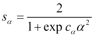

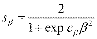
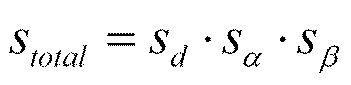
上述した図4の各処理は、どのような装置により実行されてもよい。例えば、情報処理装置において、上述した第1の3Dデータ生成処理101の第1の3Dモデリング処理と、スコアリング処理102と、第2の3Dモデリング用撮像制御処理103とが実行されてもよい。
<第2の3Dモデリング用撮像案内出力処理>
また、2回目の3Dモデリングのための撮像を制御する代わりに、2回目の3Dモデリングのための撮像を補助するための案内情報を出力してもよい。例えば、図4において、第1の3Dデータ生成処理101およびスコアリング処理102を実行し、さらに、第2の3Dモデリング用撮像案内出力処理105を実行してもよい。この場合も、第1の3Dデータ生成処理101およびスコアリング処理102は、<2.撮像制御>において上述した場合と同様に実行される。ただし、スコアリング処理102は、スコアリング結果を第2の3Dモデリング用撮像案内出力処理105へ供給する。
この案内情報を生成するために、第2の3Dモデリング用撮像案内出力処理105においては、スコアリング結果に基づいて第2の撮像を行うべき位置および姿勢(第2の撮像を行う位置および姿勢としてより適切な位置および姿勢)が求められる。この第2の撮像を行うべき位置および姿勢を求める方法はどのような方法であってもよい。例えば、上述した第2の3Dモデリング用撮像制御処理103の場合と同様の方法であってもよい。例えば、スコアリング結果に基づいて、第2の撮像が不足している部分(グレー部分)のスコアを向上させることが可能な位置および姿勢(の範囲)が特定されるようにしてもよい。
次に、案内情報の内容について説明する。この案内情報の内容は、どのようなものであってもよい。例えば、第2の撮像としてより適切な位置および姿勢をユーザに示す情報がこの案内情報に含まれていてもよい。
なお、案内情報にスコアリング結果を示す情報が含まれていてもよい。つまり、第2の3Dモデリング用撮像案内出力処理105において、スコアリング結果を示す情報を含む案内情報が生成され、そのスコアリング結果を示す画像が案内情報としてモニタに表示されてもよい。また、第2の撮像部の現在の画角内についてのスコアリング結果を示す情報が案内情報に含まれてもよい。つまり、第2の3Dモデリング用撮像案内出力処理105において、第2の撮像部の現在の位置および姿勢に基づいてその第2の撮像部の画角内についてのスコアリング結果を示す情報を含む案内情報が生成され、そのスコアリング結果を示す画像が案内情報としてモニタに表示されてもよい。
また、複数の第2の撮像画像間でその撮像範囲がオーバーラップするオーバーラップ領域を示す情報が案内情報に含まれてもよい。例えば、第2の3Dモデリング用撮像案内出力処理105において、複数の第2の撮像間でその撮像範囲がオーバーラップするオーバーラップ領域を示す情報を含む案内情報が生成され、そのオーバーラップ領域を示す画像が案内情報として表示されてもよい。例えば、図15の左において、第2の撮像部がカメラ221-1の位置および姿勢である場合、その撮像範囲が撮像範囲222-1となるとする。また、第2の撮像部がカメラ221-2の位置および姿勢である場合、その撮像範囲が撮像範囲222-2であるとする。この場合、撮像範囲222-1および撮像範囲222-2は、その一部が互いに重畳(オーバーラップ)している。このように複数の第2の撮像画像の間でその撮像範囲がオーバーラップする領域が存在することにより、両画像間の対応点の検出が可能になる。つまり、複数の第2の撮像画像の間で適切なオーバーラップ領域が存在することにより、第2の3Dモデリング処理において、高精度な第2の3Dデータを生成することができる(第2の3Dデータの精度の低減を抑制することができる)。
また、第2の撮像を補助するための撮像補助画像が案内情報に含まれてもよい。例えば、第2の3Dモデリング用撮像案内出力処理105において、第2の撮像を補助するための撮像補助画像を含む案内情報が生成され、その撮像補助画像が案内情報として表示されてもよい。この撮像補助画像の内容はどのようなものであってもよい。
図7を参照して上述したように、第2の撮像の位置として、3Dオブジェクトからの適切な距離は、その3Dオブジェクトの3次元形状に依存する。そこで、第2の3Dモデリング用撮像案内出力処理105において導出される第2の撮像の推奨撮像位置姿勢に、3Dオブジェクト(被写体)からの距離が含まれるようにしてもよい。そして、第2の3Dモデリング用撮像案内出力処理105において第2の撮像の推奨撮像位置姿勢を導出する際に、その3Dオブジェクトからの距離が、3Dオブジェクトの3次元形状の複雑度に応じて導出されてもよい。
なお、図4の第1の3Dデータ生成処理101(第1の撮像および第1の3Dモデリング処理)、スコアリング処理102、および第2の3Dモデリング用撮像案内出力処理105は、互いに並行して実行されてもよい。<2.撮像制御>において上述したように、第1の3Dモデリング処理により、3Dオブジェクトの第1の撮像が行われた部分の3Dデータを順次生成することができる。また、第1の3Dデータ生成処理101とスコアリング処理102を並行して実行することができる。
なお、この第2の3Dモデリング用撮像案内出力処理105が実行される場合も、<2.撮像制御>において上述した場合と同様に、第2の3Dデータ生成処理104(の第2の撮像)において、第2の撮像部に関するカメラ情報が生成され、スコアリング処理102へ供給されてもよい。そして、スコアリング処理102において、このカメラ情報に基づいてスコアリングが行われ、スコアリング結果が生成されてもよい。<2.撮像制御>において上述した場合と同様に、このカメラ情報はどのような情報を含んでもよい。
上述した図4の各処理は、どのような装置により実行されてもよい。例えば、情報処理装置において、上述した第1の3Dデータ生成処理101の第1の3Dモデリング処理と、スコアリング処理102と、第2の3Dモデリング用撮像案内出力処理105とが実行されてもよい。
<撮像制御と案内情報出力の組み合わせ>
なお、図4において、第2の3Dモデリング用撮像制御処理103と第2の3Dモデリング用撮像案内出力処理105の両方が実行されてもよい。撮像制御と案内情報の出力の両方を行うことにより、ユーザは、より容易に、適切な位置および姿勢で第2の撮像を行うことができる。
<3Dモデリングのための撮像作業>
ところで、上述のように、撮像画像に基づいて3Dモデリングを行う場合、より高精細な3Dデータを得るためには3Dモデリングへの貢献度が高い撮像画像が求められる。無計画に撮像作業を行うと、3Dモデリングへの貢献度が低い無駄な撮像を繰り返し、作業の負荷が不要に増大してしまうおそれがあった。撮像作業の負荷を低減させるためには、3Dモデリングへの貢献度がより高い撮像画像をより効率よく得ることが求められた。
そこで、図4に示されるように、3Dモデリング結果をフィードバックするためのフィードバック処理106を実行する。この処理を行うことで撮像作業中に3Dモデリング結果(3Dモデル)をナビゲーション等に利用することができ、ユーザは3Dモデリングのための撮像をより容易に行うことができる。
このフィードバック処理106として、例えば、最終的な3Dモデリング(フロー301の3Dモデル合成等)とは別に、フィードバックするための3Dモデリングを行ってもよい。つまり、図26のフロー302に示されるように、撮像作業と並行して3Dモデリング(3Dモデル合成)を行うようにしてもよい。当然、撮像作業中であるので、全ての撮像画像が得られた状態ではない。3Dモデル全体を構築するために必要な撮像画像が十分に得られていなくても、その時点までに得られた撮像画像を用いて、逐次的に3Dモデリングを行うようにする。このようにすることにより、撮像作業中に3Dモデリング結果(3Dモデル)が得られるので、その3Dモデルを撮像作業のナビゲーション等に利用することができる。したがって、ユーザは3Dモデリングのための撮像をより容易に行うことができる。
ところで、上述のように3Dモデリング結果を利用して撮像のナビゲーションを行う場合、複数回3Dモデリングが行われることになる。つまり、フィードバック用の3Dモデリング(例えばフォトグラメトリ処理)とは別に、端末装置等においてナビゲーション用の1回目の3Dモデリング(例えばリアルタイム3Dモデリング)が行われる。これらの3Dモデリングは互いに独立に行われる。つまり、これらの3Dモデリングにより互いに独立した座標系の3Dモデルが得られる。換言するに、フィードバック用の3Dモデリング(2回目の3Dモデリング)により得られる3Dモデルは、1回目の3Dモデリングや端末装置の姿勢情報(撮像部)とは独立した座標系で生成される。したがって、フィードバック用の3Dモデリングにより得られる3Dモデルは、1回目の3Dモデリングにより生成される3Dモデルや端末装置との位置関係が不明であった。そのため、フィードバック用の3Dモデリングにより得られる3Dモデルをナビゲーションに利用するためには、1回目の3Dモデリングにより生成される3Dモデルや端末装置との対応をユーザが感覚で構築しなければならず、煩雑な作業が必要なだけでなく、不正確な対応関係を構築し、ナビゲーションの精度が低減するおそれがあった。
このようなフィードバック用の3Dモデリングの利用について説明する。例えば、フィードバック用の3Dモデリングにおいて得られる3Dモデルを、最終的な3Dモデリングの結果を疑似的に示す情報として、表示部に表示させてもよい。
リアルタイム3Dモデリングの場合、例えば図33に示されるように矢印361のように移動しながら撮像が行われると、各撮像画像に基づいて特徴点が抽出され、その特徴点に基づいてマッチングが行われてランドマーク点362が特定され、そのランドマーク点や姿勢情報等に基づいて撮像画像の視点の位置や姿勢が特定される。キーフレーム363は、撮像画像の内、SLAMにおいてランドマーク点の生成に関与するフレームである。このキーフレーム363に基づいて3Dモデルが構築され、フォトグラメトリ用の撮像の視点364が設定される。
例えば、図36に示されるフロー381のように、ユーザが撮像作業を中断し、しばらくしてから撮像作業を再開するケースが考えられる。このような場合、従来のような方法では、中断前の3Dモデリングと再開後の3Dモデリングは互いに独立に行われ、座標系が互いに独立する。つまり、ユーザが撮像作業を中断することにより、第1の3Dモデリングがいったん終了すると、中断前の座標系を引き継ぐことができない。そのため、再開後の姿勢情報の精度(つまりナビゲーションの精度)が低減するおそれがあった。
また、例えば、図37に示されるフロー391のように、複数のユーザ(例えばユーザAとユーザB)が共同で撮像作業を行うケースが考えられる。例えば、複数ユーザが大きな1つの3Dオブジェクトの3Dモデルを生成するケースが考えられる。このような場合に、従来の方法では、各ユーザの3Dモデリングは、互いに独立の座標系で行われることになる。そのため、各ユーザが生成した3Dモデルを統合する煩雑な作業が必要であった。
なお、フィードバック用の3Dモデルは、他の装置から供給されてもよいし、フィードバック用の3Dモデリングを行って生成してもよい。つまり、上述した情報処理装置が、第2の3Dモデリング処理を行う第2の3Dモデリング処理部をさらに備えてもよい。また、上述した情報処理装置が、その第2の3Dモデリング処理に適用される第2の撮像画像を生成する第2の撮像部をさらに備えてもよい。
<撮像装置>
図39は、本技術を適用した情報処理装置の一態様である撮像装置の構成の一例を示すブロック図である。図39に示される撮像装置1300は、3Dオブジェクトを撮像し、その撮像画像を用いて3Dモデリングを行う装置である。なお、図39においては、処理部やデータの流れ等の主なものを示しており、図39に示されるものが全てとは限らない。つまり、撮像装置1300が、図39においてブロックとして示されていない装置や処理部を有してもよい。また、図39において矢印等として示されていないデータの流れや処理が存在してもよい。
この撮像装置1300により実行される3Dモデリング処理の流れの例を図40のフローチャートを参照して説明する。
図40のステップS302において実行されるリアルタイム3Dモデリング処理の流れの例を、図41のフローチャートを参照して説明する。
図40のステップS309において実行されるフォトグラメトリ処理の流れの例を、図42のフローチャートを参照して説明する。
<情報処理システム1>
本技術は、上述の例に限定されず、任意の構成に適用し得る。例えば、3Dモデリングを行う情報処理システムに適用してもよい。
この情報処理システム1400により実行される3Dモデリング処理の流れの例を図47および図48のフローチャートを参照して説明する。
なお、情報処理システム1400において、スコアリング処理をサーバ1403で行ってもよい。
この場合の情報処理システム1400により実行される3Dモデリング処理の流れの例を図51および図52のフローチャートを参照して説明する。
<フィードバック処理の適用>
<5.フィードバック処理>において上述した本技術は、任意の情報処理装置に適用することができる。例えば、その本技術は、第1の実施の形態および第2の実施の形態において説明したいずれかのシステムや装置に適用することができる。また、本技術は、上述した以外の装置やシステムにも適用し得る。
例えば、<5.フィードバック処理>において上述した本技術は、図53の情報処理システム1600に適用されてもよい。以下においては、その場合について説明する。
図54は、その撮像通信装置1601の主な構成例を示すブロック図である。なお、図54においては、処理部やデータの流れ等の主なものを示しており、図54に示されるものが全てとは限らない。つまり、撮像通信装置1601が、図54においてブロックとして示されていない装置や処理部を有してもよい。また、図54において矢印等として示されていないデータの流れや処理が存在してもよい。
図55は、サーバ1602の主な構成例を示すブロック図である。図55に示されるように、サーバ1602は、例えば、通信部1621、記憶部1622、およびフォトグラメトリ処理部1623を有する。通信部1621は、撮像通信装置1601や情報処理装置1603等と通信を行い、情報を授受する。記憶部1622は、第2の撮像画像や第2の3Dデータ等、各種情報を記憶する。フォトグラメトリ処理部1623は、SfM1341およびMVS1342を有する。つまり、フォトグラメトリ処理部1623は、フォトグラメトリ処理部1334と同様のフォトグラメトリ処理を行う。
図56は、情報処理装置1603の主な構成例を示すブロック図である。図56に示されるように、情報処理装置1603は、通信部1641、フォトグラメトリ処理部1334、表示制御部1643、および表示部1644を有する。
撮像通信装置1601により実行される3Dモデリング処理の流れの例を図57のフローチャートを参照して説明する。
次に、図58のフローチャートを参照して、サーバ1602において実行されるインクリメント3Dモデリング処理の流れの例を説明する。
図59のフローチャートを参照して、撮像通信装置1601により実行される表示制御処理の流れの例を説明する。
図60のフローチャートを参照して、撮像通信装置1601により実行される座標補正処理の流れの例を説明する。
なお、フィードバック用の3Dモデリング(第2の3Dモデリング)は、撮像通信装置1601において行われてもよい。その場合、撮像通信装置1601は、図61に示されるように、図54の構成だけでなく、図55のサーバ1602の構成も有するようにすればよい。つまり、この場合、撮像通信装置1601は、図54に示される構成に加え、フォトグラメトリ処理部1623を有する。このフォトグラメトリ処理部1623は、図55を参照して説明した場合と同様の処理を行う。つまり、この場合、撮像通信装置1601は、<5.フィードバック処理>において上述した各処理を実行し得る。したがって、撮像通信装置1601は、フィードバック用の3Dモデリングにより得られる3Dモデルをより容易にナビゲーションに利用することができる。また、その場合、撮像通信装置1601は、ナビゲーションの精度の低減を抑制することができる。したがって、撮像通信装置1601は、3Dモデリングのための撮像をより容易に行うことができる。
<コンピュータ>
上述した一連の処理は、ハードウエアにより実行させることもできるし、ソフトウエアにより実行させることもできる。一連の処理をソフトウエアにより実行する場合には、そのソフトウエアを構成するプログラムが、コンピュータにインストールされる。ここでコンピュータには、専用のハードウエアに組み込まれているコンピュータや、各種のプログラムをインストールすることで、各種の機能を実行することが可能な、例えば汎用のパーソナルコンピュータ等が含まれる。
本技術は、任意の構成に適用することができる。例えば、本技術は、様々な電子機器に適用され得る。
なお、本明細書において、「関連付ける」という用語は、例えば、一方のデータを処理する際に他方のデータを利用し得る(リンクさせ得る)ようにすることを意味する。つまり、互いに関連付けられたデータは、1つのデータとしてまとめられてもよいし、それぞれ個別のデータとしてもよい。例えば、あるデータに関連付けられた情報は、そのデータとは別の伝送路上で伝送されるようにしてもよい。また、例えば、あるデータに関連付けられた情報は、そのデータとは別の記録媒体(または同一の記録媒体の別の記録エリア)に記録されるようにしてもよい。なお、この「関連付け」は、データ全体でなく、データの一部であってもよい。例えば、動的な3Dデータとその動的な3Dデータに対応する情報とが、複数フレーム、1フレーム、またはフレーム内の一部分などの任意の単位で互いに関連付けられるようにしてもよい。
(1) 第1の3Dモデリング処理を行う第1の3Dモデリング処理部と、
前記第1の3Dモデリング処理を制御し、前記第1の3Dモデリング処理の座標系を第2の3Dモデリング処理の座標系と対応させる座標制御部と
を備え、
前記第1の3Dモデリング処理は、第1の撮像画像に基づいて3Dオブジェクトの3次元形状を表現する第1の3次元形状情報を生成する処理であり、
前記第1の撮像画像は、第1の撮像部が前記3Dオブジェクトを撮像する第1の撮像により生成され、
前記第2の3Dモデリング処理は、第2の撮像画像に基づいて前記3Dオブジェクトの3次元形状を表現する第2の3次元形状情報を生成する処理であり、
前記第2の撮像画像は、第2の撮像部が前記第1の3次元形状情報に基づいて前記3Dオブジェクトを撮像する第2の撮像により生成される
情報処理装置。
(2) 前記座標制御部は、前記第1の3Dモデリング処理部が前記第1の3Dモデリング処理を開始する際に前記座標系を対応させる
(1)に記載の情報処理装置。
(3) 前記座標制御部は、前記第2の3Dモデリング処理により得られる前記第2の撮像画像の視点の位置および姿勢を用いて、前記第1の撮像画像の視点の位置および姿勢を補正する
(1)または(2)に記載の情報処理装置。
(4) 前記第2の3Dモデリング処理により生成される、前記第1の3次元形状情報と対応する座標系の前記第2の3次元形状情報を表示部に表示させる表示制御部をさらに備える
(1)乃至(3)のいずれかに記載の情報処理装置。
(5) 前記表示制御部は、前記第2の3次元形状情報を、前記第1の撮像部の現在の位置および姿勢に対応する視点で表示させる
(4)に記載の情報処理装置。
(6) 前記表示制御部は、前記第2の3次元形状情報を、任意の視点で表示させる
(4)または(5)に記載の情報処理装置。
(7) 前記表示制御部は、前記表示部の表示領域を分割し、前記第1の撮像部の現在の位置および姿勢に対応する視点の前記第2の3次元形状情報と、任意の視点の前記第2の3次元形状情報とを、互いに異なる表示領域に表示させる
(4)乃至(6)のいずれかに記載の情報処理装置。
(8) 前記表示制御部は、さらに、前記第1の3次元形状情報を前記第2の3次元形状情報に重畳させて表示させる
(4)乃至(7)のいずれかに記載の情報処理装置。
(9) 前記表示制御部は、前記表示部の表示領域を分割し、前記第1の3次元形状情報および前記第2の3次元形状情報を、互いに異なる表示領域に表示させる
(4)乃至(7)のいずれかに記載の情報処理装置。
(10) 前記表示制御部は、前記第1の3次元形状情報および前記第2の3次元形状情報を、互いに同一の視点で表示させる
(9)に記載の情報処理装置。
(11) 前記表示制御部は、さらに、これまでに得られた前記第2の撮像画像の視点を示す画像を前記第2の3次元形状情報に重畳させて表示させる
(4)乃至(10)のいずれかに記載の情報処理装置。
(12) 前記表示制御部は、さらに、前記視点に対応する前記第2の撮像画像を前記第2の3次元形状情報に重畳させて表示させる
(11)に記載の情報処理装置。
(13) 前記表示制御部は、さらに、前記視点からの撮像範囲を示す画像を前記第2の3次元形状情報に重畳させて表示させる
(11)または(12)に記載の情報処理装置。
(14) 前記表示制御部は、さらに、前記第2の3次元形状情報に基づいて導出されるスコアを前記第2の3次元形状情報に重畳させて表示させ、
前記スコアは、これまでに生成された前記第2の撮像画像を用いて生成可能な前記第2の3次元形状情報の精度の評価値である
(4)乃至(13)のいずれかに記載の情報処理装置。
(15) 前記表示部をさらに備える
(4)乃至(14)のいずれかに記載の情報処理装置。
(16) 前記第2の3Dモデリング処理を行う第2の3Dモデリング処理部をさらに備える
(1)乃至(15)のいずれかに記載の情報処理装置。
(17) 前記第2の撮像部をさらに備える
(1)乃至(16)のいずれかに記載の情報処理装置。
(18) 第1の3Dモデリング処理を行い、
前記第1の3Dモデリング処理を制御し、前記第1の3Dモデリング処理の座標系を第2の3Dモデリング処理の座標系と対応させ、
前記第1の3Dモデリング処理は、第1の撮像画像に基づいて3Dオブジェクトの3次元形状を表現する第1の3次元形状情報を生成し、
前記第1の撮像画像は、第1の撮像部が前記3Dオブジェクトを撮像する第1の撮像により生成され、
前記第2の3Dモデリング処理は、第2の撮像画像に基づいて前記3Dオブジェクトの3次元形状を表現する第2の3次元形状情報を生成し、
前記第2の撮像画像は、第2の撮像部が前記第1の3次元形状情報に基づいて前記3Dオブジェクトを撮像する第2の撮像により生成される
情報処理方法。
前記第2の3Dモデリング処理を制御し、前記第2の3Dモデリング処理の座標系を前記第1の3Dモデリング処理の座標系と対応させる座標制御部と
を備え、
前記第1の3Dモデリング処理は、第1の撮像画像に基づいて3Dオブジェクトの3次元形状を表現する第1の3次元形状情報を生成する処理であり、
前記第1の撮像画像は、第1の撮像部が前記3Dオブジェクトを撮像する第1の撮像により生成され、
前記第2の3Dモデリング処理は、第2の撮像画像に基づいて前記3Dオブジェクトの3次元形状を表現する第2の3次元形状情報を生成する処理であり、
前記第2の撮像画像は、第2の撮像部が前記第1の3次元形状情報に基づいて前記3Dオブジェクトを撮像する第2の撮像により生成される
情報処理装置。
(20) 第1の3Dモデリング処理とは異なる第2の3Dモデリング処理を行い、
前記第2の3Dモデリング処理を制御し、前記第2の3Dモデリング処理の座標系を前記第1の3Dモデリング処理の座標系と対応させ、
前記第1の3Dモデリング処理は、第1の撮像画像に基づいて3Dオブジェクトの3次元形状を表現する第1の3次元形状情報を生成し、
前記第1の撮像画像は、第1の撮像部が前記3Dオブジェクトを撮像する第1の撮像により生成され、
前記第2の3Dモデリング処理は、第2の撮像画像に基づいて前記3Dオブジェクトの3次元形状を表現する第2の3次元形状情報を生成し、
前記第2の撮像画像は、第2の撮像部が前記第1の3次元形状情報に基づいて前記3Dオブジェクトを撮像する第2の撮像により生成される
情報処理方法。
Claims (20)
- 第1の3Dモデリング処理を行う第1の3Dモデリング処理部と、
前記第1の3Dモデリング処理を制御し、前記第1の3Dモデリング処理の座標系を第2の3Dモデリング処理の座標系と対応させる座標制御部と
を備え、
前記第1の3Dモデリング処理は、第1の撮像画像に基づいて3Dオブジェクトの3次元形状を表現する第1の3次元形状情報を生成する処理であり、
前記第1の撮像画像は、第1の撮像部が前記3Dオブジェクトを撮像する第1の撮像により生成され、
前記第2の3Dモデリング処理は、第2の撮像画像に基づいて前記3Dオブジェクトの3次元形状を表現する第2の3次元形状情報を生成する処理であり、
前記第2の撮像画像は、第2の撮像部が前記第1の3次元形状情報に基づいて前記3Dオブジェクトを撮像する第2の撮像により生成される
情報処理装置。 - 前記座標制御部は、前記第1の3Dモデリング処理部が前記第1の3Dモデリング処理を開始する際に前記座標系を対応させる
請求項1に記載の情報処理装置。 - 前記座標制御部は、前記第2の3Dモデリング処理により得られる前記第2の撮像画像の視点の位置および姿勢を用いて、前記第1の撮像画像の視点の位置および姿勢を補正する 請求項1に記載の情報処理装置。
- 前記第2の3Dモデリング処理により生成される、前記第1の3次元形状情報と対応する座標系の前記第2の3次元形状情報を表示部に表示させる表示制御部をさらに備える
請求項1に記載の情報処理装置。 - 前記表示制御部は、前記第2の3次元形状情報を、前記第1の撮像部の現在の位置および姿勢に対応する視点で表示させる
請求項4に記載の情報処理装置。 - 前記表示制御部は、前記第2の3次元形状情報を、任意の視点で表示させる
請求項4に記載の情報処理装置。 - 前記表示制御部は、前記表示部の表示領域を分割し、前記第1の撮像部の現在の位置および姿勢に対応する視点の前記第2の3次元形状情報と、任意の視点の前記第2の3次元形状情報とを、互いに異なる表示領域に表示させる
請求項4に記載の情報処理装置。 - 前記表示制御部は、さらに、前記第1の3次元形状情報を前記第2の3次元形状情報に重畳させて表示させる
請求項4に記載の情報処理装置。 - 前記表示制御部は、前記表示部の表示領域を分割し、前記第1の3次元形状情報および前記第2の3次元形状情報を、互いに異なる表示領域に表示させる
請求項4に記載の情報処理装置。 - 前記表示制御部は、前記第1の3次元形状情報および前記第2の3次元形状情報を、互いに同一の視点で表示させる
請求項9に記載の情報処理装置。 - 前記表示制御部は、さらに、これまでに得られた前記第2の撮像画像の視点を示す画像を前記第2の3次元形状情報に重畳させて表示させる
請求項4に記載の情報処理装置。 - 前記表示制御部は、さらに、前記視点に対応する前記第2の撮像画像を前記第2の3次元形状情報に重畳させて表示させる
請求項11に記載の情報処理装置。 - 前記表示制御部は、さらに、前記視点からの撮像範囲を示す画像を前記第2の3次元形状情報に重畳させて表示させる
請求項11に記載の情報処理装置。 - 前記表示制御部は、さらに、前記第2の3次元形状情報に基づいて導出されるスコアを前記第2の3次元形状情報に重畳させて表示させ、
前記スコアは、これまでに生成された前記第2の撮像画像を用いて生成可能な前記第2の3次元形状情報の精度の評価値である
請求項4に記載の情報処理装置。 - 前記表示部をさらに備える
請求項4に記載の情報処理装置。 - 前記第2の3Dモデリング処理を行う第2の3Dモデリング処理部をさらに備える
請求項1に記載の情報処理装置。 - 前記第2の撮像部をさらに備える
請求項1に記載の情報処理装置。 - 第1の3Dモデリング処理を行い、
前記第1の3Dモデリング処理を制御し、前記第1の3Dモデリング処理の座標系を第2の3Dモデリング処理の座標系と対応させ、
前記第1の3Dモデリング処理は、第1の撮像画像に基づいて3Dオブジェクトの3次元形状を表現する第1の3次元形状情報を生成し、
前記第1の撮像画像は、第1の撮像部が前記3Dオブジェクトを撮像する第1の撮像により生成され、
前記第2の3Dモデリング処理は、第2の撮像画像に基づいて前記3Dオブジェクトの3次元形状を表現する第2の3次元形状情報を生成し、
前記第2の撮像画像は、第2の撮像部が前記第1の3次元形状情報に基づいて前記3Dオブジェクトを撮像する第2の撮像により生成される
情報処理方法。 - 第1の3Dモデリング処理とは異なる第2の3Dモデリング処理を行う第2の3Dモデリング処理部と、
前記第2の3Dモデリング処理を制御し、前記第2の3Dモデリング処理の座標系を前記第1の3Dモデリング処理の座標系と対応させる座標制御部と
を備え、
前記第1の3Dモデリング処理は、第1の撮像画像に基づいて3Dオブジェクトの3次元形状を表現する第1の3次元形状情報を生成する処理であり、
前記第1の撮像画像は、第1の撮像部が前記3Dオブジェクトを撮像する第1の撮像により生成され、
前記第2の3Dモデリング処理は、第2の撮像画像に基づいて前記3Dオブジェクトの3次元形状を表現する第2の3次元形状情報を生成する処理であり、
前記第2の撮像画像は、第2の撮像部が前記第1の3次元形状情報に基づいて前記3Dオブジェクトを撮像する第2の撮像により生成される
情報処理装置。 - 第1の3Dモデリング処理とは異なる第2の3Dモデリング処理を行い、
前記第2の3Dモデリング処理を制御し、前記第2の3Dモデリング処理の座標系を前記第1の3Dモデリング処理の座標系と対応させ、
前記第1の3Dモデリング処理は、第1の撮像画像に基づいて3Dオブジェクトの3次元形状を表現する第1の3次元形状情報を生成し、
前記第1の撮像画像は、第1の撮像部が前記3Dオブジェクトを撮像する第1の撮像により生成され、
前記第2の3Dモデリング処理は、第2の撮像画像に基づいて前記3Dオブジェクトの3次元形状を表現する第2の3次元形状情報を生成し、
前記第2の撮像画像は、第2の撮像部が前記第1の3次元形状情報に基づいて前記3Dオブジェクトを撮像する第2の撮像により生成される
情報処理方法。
Priority Applications (2)
| Application Number | Priority Date | Filing Date | Title |
|---|---|---|---|
| EP23906701.0A EP4641501A4 (en) | 2022-12-23 | 2023-12-05 | INFORMATION PROCESSING DEVICE AND METHOD |
| JP2024565760A JPWO2024135335A1 (ja) | 2022-12-23 | 2023-12-05 |
Applications Claiming Priority (2)
| Application Number | Priority Date | Filing Date | Title |
|---|---|---|---|
| JP2022-206610 | 2022-12-23 | ||
| JP2022206610 | 2022-12-23 |
Publications (1)
| Publication Number | Publication Date |
|---|---|
| WO2024135335A1 true WO2024135335A1 (ja) | 2024-06-27 |
Family
ID=91588466
Family Applications (1)
| Application Number | Title | Priority Date | Filing Date |
|---|---|---|---|
| PCT/JP2023/043392 Ceased WO2024135335A1 (ja) | 2022-12-23 | 2023-12-05 | 情報処理装置および方法 |
Country Status (3)
| Country | Link |
|---|---|
| EP (1) | EP4641501A4 (ja) |
| JP (1) | JPWO2024135335A1 (ja) |
| WO (1) | WO2024135335A1 (ja) |
Cited By (2)
| Publication number | Priority date | Publication date | Assignee | Title |
|---|---|---|---|---|
| CN119152110A (zh) * | 2024-08-13 | 2024-12-17 | 同济大学 | 一种箭头优化建模方法及装置 |
| WO2026070326A1 (ja) * | 2024-09-27 | 2026-04-02 | 富士フイルム株式会社 | コンテンツ生成装置、コンテンツ生成方法、プログラム、及び記録媒体 |
Citations (5)
| Publication number | Priority date | Publication date | Assignee | Title |
|---|---|---|---|---|
| JP2011192228A (ja) * | 2010-03-17 | 2011-09-29 | Casio Computer Co Ltd | 三次元モデリング装置、三次元モデリング方法、ならびに、プログラム |
| JP2011209815A (ja) * | 2010-03-29 | 2011-10-20 | Casio Computer Co Ltd | 三次元モデリング装置、三次元モデリング方法、ならびに、プログラム |
| JP2012221128A (ja) * | 2011-04-06 | 2012-11-12 | Casio Comput Co Ltd | 三次元モデリング装置、三次元モデリング方法、ならびに、プログラム |
| US20200051277A1 (en) * | 2017-04-26 | 2020-02-13 | Hewlett-Packard Development Company, L.P. | Locating a region of interest on an object |
| WO2022075073A1 (ja) * | 2020-10-07 | 2022-04-14 | ソニーグループ株式会社 | 撮影デバイス、サーバ装置、および、3dデータ生成方法 |
Family Cites Families (3)
| Publication number | Priority date | Publication date | Assignee | Title |
|---|---|---|---|---|
| US10574974B2 (en) * | 2014-06-27 | 2020-02-25 | A9.Com, Inc. | 3-D model generation using multiple cameras |
| JP7013144B2 (ja) | 2016-10-12 | 2022-01-31 | キヤノン株式会社 | 画像処理装置、画像処理方法およびプログラム |
| WO2022150904A1 (en) * | 2021-01-12 | 2022-07-21 | John Zelek | System and method of hybrid scene representation for visual simultaneous localization and mapping |
-
2023
- 2023-12-05 WO PCT/JP2023/043392 patent/WO2024135335A1/ja not_active Ceased
- 2023-12-05 EP EP23906701.0A patent/EP4641501A4/en active Pending
- 2023-12-05 JP JP2024565760A patent/JPWO2024135335A1/ja active Pending
Patent Citations (5)
| Publication number | Priority date | Publication date | Assignee | Title |
|---|---|---|---|---|
| JP2011192228A (ja) * | 2010-03-17 | 2011-09-29 | Casio Computer Co Ltd | 三次元モデリング装置、三次元モデリング方法、ならびに、プログラム |
| JP2011209815A (ja) * | 2010-03-29 | 2011-10-20 | Casio Computer Co Ltd | 三次元モデリング装置、三次元モデリング方法、ならびに、プログラム |
| JP2012221128A (ja) * | 2011-04-06 | 2012-11-12 | Casio Comput Co Ltd | 三次元モデリング装置、三次元モデリング方法、ならびに、プログラム |
| US20200051277A1 (en) * | 2017-04-26 | 2020-02-13 | Hewlett-Packard Development Company, L.P. | Locating a region of interest on an object |
| WO2022075073A1 (ja) * | 2020-10-07 | 2022-04-14 | ソニーグループ株式会社 | 撮影デバイス、サーバ装置、および、3dデータ生成方法 |
Cited By (2)
| Publication number | Priority date | Publication date | Assignee | Title |
|---|---|---|---|---|
| CN119152110A (zh) * | 2024-08-13 | 2024-12-17 | 同济大学 | 一种箭头优化建模方法及装置 |
| WO2026070326A1 (ja) * | 2024-09-27 | 2026-04-02 | 富士フイルム株式会社 | コンテンツ生成装置、コンテンツ生成方法、プログラム、及び記録媒体 |
Also Published As
| Publication number | Publication date |
|---|---|
| JPWO2024135335A1 (ja) | 2024-06-27 |
| EP4641501A1 (en) | 2025-10-29 |
| EP4641501A4 (en) | 2026-03-25 |
Similar Documents
| Publication | Publication Date | Title |
|---|---|---|
| US8928736B2 (en) | Three-dimensional modeling apparatus, three-dimensional modeling method and computer-readable recording medium storing three-dimensional modeling program | |
| CN111837144B (zh) | 使用机器学习的增强图像深度感测 | |
| US9332243B2 (en) | Handheld portable optical scanner and method of using | |
| WO2024080120A1 (ja) | 情報処理装置および方法、並びに、情報処理システム | |
| JP4473754B2 (ja) | 仮想試着装置 | |
| EP3994660A1 (en) | Method and system for image generation | |
| US20110249117A1 (en) | Imaging device, distance measuring method, and non-transitory computer-readable recording medium storing a program | |
| US20120069018A1 (en) | Ar process apparatus, ar process method and storage medium | |
| JP2019153863A (ja) | 画像処理装置、符号化装置、復号化装置、画像処理方法、プログラム、符号化方法及び復号化方法 | |
| CN110969706B (zh) | 增强现实设备及其图像处理方法、系统以及存储介质 | |
| EP4641501A1 (en) | Information processing device and method | |
| US20250168315A1 (en) | Multiview interactive digital media representation inventory verification | |
| CN116385554B (zh) | 一种基于双无人机视频拼接的近岸海域水深测绘方法 | |
| WO2024080121A1 (ja) | 情報処理装置および方法 | |
| JP2011146762A (ja) | 立体モデル生成装置 | |
| CN120451365B (zh) | 基于双目摄像头与imu的3d动态定位与渲染系统及方法 | |
| WO2024150626A1 (ja) | 情報処理装置および方法 | |
| WO2025033147A1 (ja) | 情報処理方法、情報処理装置、プログラム | |
| JP2023047882A (ja) | 画像生成装置、画像生成方法およびプログラム | |
| WO2024135336A1 (ja) | 情報処理装置および方法 | |
| WO2024135337A1 (ja) | 情報処理装置および方法 | |
| JP7708089B2 (ja) | 情報処理装置、情報処理方法及びコンピュータプログラム | |
| WO2024181137A1 (ja) | 情報処理装置および方法 | |
| JP2020201767A (ja) | 情報処理装置、情報処理システム、情報処理方法、及びプログラム | |
| WO2025033166A1 (ja) | 撮像装置、撮像方法、およびプログラム |
Legal Events
| Date | Code | Title | Description |
|---|---|---|---|
| 121 | Ep: the epo has been informed by wipo that ep was designated in this application |
Ref document number: 23906701 Country of ref document: EP Kind code of ref document: A1 |
|
| WWE | Wipo information: entry into national phase |
Ref document number: 2024565760 Country of ref document: JP |
|
| WWE | Wipo information: entry into national phase |
Ref document number: 2023906701 Country of ref document: EP |
|
| NENP | Non-entry into the national phase |
Ref country code: DE |
|
| ENP | Entry into the national phase |
Ref document number: 2023906701 Country of ref document: EP Effective date: 20250723 |
|
| ENP | Entry into the national phase |
Ref document number: 2023906701 Country of ref document: EP Effective date: 20250723 |
|
| ENP | Entry into the national phase |
Ref document number: 2023906701 Country of ref document: EP Effective date: 20250723 |
|
| WWP | Wipo information: published in national office |
Ref document number: 2023906701 Country of ref document: EP |