WO2024135704A1 - 状態識別装置を生産する方法および状態識別装置 - Google Patents
状態識別装置を生産する方法および状態識別装置 Download PDFInfo
- Publication number
- WO2024135704A1 WO2024135704A1 PCT/JP2023/045571 JP2023045571W WO2024135704A1 WO 2024135704 A1 WO2024135704 A1 WO 2024135704A1 JP 2023045571 W JP2023045571 W JP 2023045571W WO 2024135704 A1 WO2024135704 A1 WO 2024135704A1
- Authority
- WO
- WIPO (PCT)
- Prior art keywords
- signal
- state
- vehicle
- identification
- period
- Prior art date
- Legal status (The legal status is an assumption and is not a legal conclusion. Google has not performed a legal analysis and makes no representation as to the accuracy of the status listed.)
- Ceased
Links
Images

Classifications
-
- B—PERFORMING OPERATIONS; TRANSPORTING
- B60—VEHICLES IN GENERAL
- B60W—CONJOINT CONTROL OF VEHICLE SUB-UNITS OF DIFFERENT TYPE OR DIFFERENT FUNCTION; CONTROL SYSTEMS SPECIALLY ADAPTED FOR HYBRID VEHICLES; ROAD VEHICLE DRIVE CONTROL SYSTEMS FOR PURPOSES NOT RELATED TO THE CONTROL OF A PARTICULAR SUB-UNIT
- B60W50/00—Details of control systems for road vehicle drive control not related to the control of a particular sub-unit, e.g. process diagnostic or vehicle driver interfaces
- B60W50/02—Ensuring safety in case of control system failures, e.g. by diagnosing, circumventing or fixing failures
- B60W50/0205—Diagnosing or detecting failures; Failure detection models
-
- B—PERFORMING OPERATIONS; TRANSPORTING
- B60—VEHICLES IN GENERAL
- B60W—CONJOINT CONTROL OF VEHICLE SUB-UNITS OF DIFFERENT TYPE OR DIFFERENT FUNCTION; CONTROL SYSTEMS SPECIALLY ADAPTED FOR HYBRID VEHICLES; ROAD VEHICLE DRIVE CONTROL SYSTEMS FOR PURPOSES NOT RELATED TO THE CONTROL OF A PARTICULAR SUB-UNIT
- B60W40/00—Estimation or calculation of non-directly measurable driving parameters for road vehicle drive control systems not related to the control of a particular sub unit, e.g. by using mathematical models
-
- B—PERFORMING OPERATIONS; TRANSPORTING
- B60—VEHICLES IN GENERAL
- B60W—CONJOINT CONTROL OF VEHICLE SUB-UNITS OF DIFFERENT TYPE OR DIFFERENT FUNCTION; CONTROL SYSTEMS SPECIALLY ADAPTED FOR HYBRID VEHICLES; ROAD VEHICLE DRIVE CONTROL SYSTEMS FOR PURPOSES NOT RELATED TO THE CONTROL OF A PARTICULAR SUB-UNIT
- B60W50/00—Details of control systems for road vehicle drive control not related to the control of a particular sub-unit, e.g. process diagnostic or vehicle driver interfaces
- B60W50/04—Monitoring the functioning of the control system
-
- B—PERFORMING OPERATIONS; TRANSPORTING
- B60—VEHICLES IN GENERAL
- B60W—CONJOINT CONTROL OF VEHICLE SUB-UNITS OF DIFFERENT TYPE OR DIFFERENT FUNCTION; CONTROL SYSTEMS SPECIALLY ADAPTED FOR HYBRID VEHICLES; ROAD VEHICLE DRIVE CONTROL SYSTEMS FOR PURPOSES NOT RELATED TO THE CONTROL OF A PARTICULAR SUB-UNIT
- B60W50/00—Details of control systems for road vehicle drive control not related to the control of a particular sub-unit, e.g. process diagnostic or vehicle driver interfaces
- B60W50/08—Interaction between the driver and the control system
- B60W50/14—Means for informing the driver, warning the driver or prompting a driver intervention
-
- F—MECHANICAL ENGINEERING; LIGHTING; HEATING; WEAPONS; BLASTING
- F01—MACHINES OR ENGINES IN GENERAL; ENGINE PLANTS IN GENERAL; STEAM ENGINES
- F01N—GAS-FLOW SILENCERS OR EXHAUST APPARATUS FOR MACHINES OR ENGINES IN GENERAL; GAS-FLOW SILENCERS OR EXHAUST APPARATUS FOR INTERNAL-COMBUSTION ENGINES
- F01N11/00—Monitoring or diagnostic devices for exhaust-gas treatment apparatus
-
- F—MECHANICAL ENGINEERING; LIGHTING; HEATING; WEAPONS; BLASTING
- F02—COMBUSTION ENGINES; HOT-GAS OR COMBUSTION-PRODUCT ENGINE PLANTS
- F02D—CONTROLLING COMBUSTION ENGINES
- F02D29/00—Controlling engines, such controlling being peculiar to the devices driven thereby, the devices being other than parts or accessories essential to engine operation, e.g. controlling of engines by signals external thereto
- F02D29/02—Controlling engines, such controlling being peculiar to the devices driven thereby, the devices being other than parts or accessories essential to engine operation, e.g. controlling of engines by signals external thereto peculiar to engines driving vehicles; peculiar to engines driving variable pitch propellers
-
- F—MECHANICAL ENGINEERING; LIGHTING; HEATING; WEAPONS; BLASTING
- F02—COMBUSTION ENGINES; HOT-GAS OR COMBUSTION-PRODUCT ENGINE PLANTS
- F02D—CONTROLLING COMBUSTION ENGINES
- F02D41/00—Electrical control of supply of combustible mixture or its constituents
- F02D41/02—Circuit arrangements for generating control signals
- F02D41/14—Introducing closed-loop corrections
- F02D41/1438—Introducing closed-loop corrections using means for determining characteristics of the combustion gases; Sensors therefor
- F02D41/1439—Introducing closed-loop corrections using means for determining characteristics of the combustion gases; Sensors therefor characterised by the position of the sensor
- F02D41/1441—Plural sensors
-
- F—MECHANICAL ENGINEERING; LIGHTING; HEATING; WEAPONS; BLASTING
- F02—COMBUSTION ENGINES; HOT-GAS OR COMBUSTION-PRODUCT ENGINE PLANTS
- F02D—CONTROLLING COMBUSTION ENGINES
- F02D41/00—Electrical control of supply of combustible mixture or its constituents
- F02D41/02—Circuit arrangements for generating control signals
- F02D41/14—Introducing closed-loop corrections
- F02D41/1438—Introducing closed-loop corrections using means for determining characteristics of the combustion gases; Sensors therefor
- F02D41/1444—Introducing closed-loop corrections using means for determining characteristics of the combustion gases; Sensors therefor characterised by the characteristics of the combustion gases
- F02D41/1454—Introducing closed-loop corrections using means for determining characteristics of the combustion gases; Sensors therefor characterised by the characteristics of the combustion gases the characteristics being an oxygen content or concentration or the air-fuel ratio
-
- F—MECHANICAL ENGINEERING; LIGHTING; HEATING; WEAPONS; BLASTING
- F02—COMBUSTION ENGINES; HOT-GAS OR COMBUSTION-PRODUCT ENGINE PLANTS
- F02D—CONTROLLING COMBUSTION ENGINES
- F02D41/00—Electrical control of supply of combustible mixture or its constituents
- F02D41/22—Safety or indicating devices for abnormal conditions
-
- G—PHYSICS
- G05—CONTROLLING; REGULATING
- G05B—CONTROL OR REGULATING SYSTEMS IN GENERAL; FUNCTIONAL ELEMENTS OF SUCH SYSTEMS; MONITORING OR TESTING ARRANGEMENTS FOR SUCH SYSTEMS OR ELEMENTS
- G05B23/00—Testing or monitoring of control systems or parts thereof
- G05B23/02—Electric testing or monitoring
- G05B23/0205—Electric testing or monitoring by means of a monitoring system capable of detecting and responding to faults
- G05B23/0218—Electric testing or monitoring by means of a monitoring system capable of detecting and responding to faults characterised by the fault detection method dealing with either existing or incipient faults
- G05B23/0224—Process history based detection method, e.g. whereby history implies the availability of large amounts of data
-
- B—PERFORMING OPERATIONS; TRANSPORTING
- B60—VEHICLES IN GENERAL
- B60W—CONJOINT CONTROL OF VEHICLE SUB-UNITS OF DIFFERENT TYPE OR DIFFERENT FUNCTION; CONTROL SYSTEMS SPECIALLY ADAPTED FOR HYBRID VEHICLES; ROAD VEHICLE DRIVE CONTROL SYSTEMS FOR PURPOSES NOT RELATED TO THE CONTROL OF A PARTICULAR SUB-UNIT
- B60W50/00—Details of control systems for road vehicle drive control not related to the control of a particular sub-unit, e.g. process diagnostic or vehicle driver interfaces
- B60W50/02—Ensuring safety in case of control system failures, e.g. by diagnosing, circumventing or fixing failures
- B60W50/0205—Diagnosing or detecting failures; Failure detection models
- B60W2050/021—Means for detecting failure or malfunction
-
- F—MECHANICAL ENGINEERING; LIGHTING; HEATING; WEAPONS; BLASTING
- F01—MACHINES OR ENGINES IN GENERAL; ENGINE PLANTS IN GENERAL; STEAM ENGINES
- F01N—GAS-FLOW SILENCERS OR EXHAUST APPARATUS FOR MACHINES OR ENGINES IN GENERAL; GAS-FLOW SILENCERS OR EXHAUST APPARATUS FOR INTERNAL-COMBUSTION ENGINES
- F01N2560/00—Exhaust systems with means for detecting or measuring exhaust gas components or characteristics
- F01N2560/02—Exhaust systems with means for detecting or measuring exhaust gas components or characteristics the means being an exhaust gas sensor
- F01N2560/025—Exhaust systems with means for detecting or measuring exhaust gas components or characteristics the means being an exhaust gas sensor for measuring or detecting O2, e.g. lambda sensors
-
- F—MECHANICAL ENGINEERING; LIGHTING; HEATING; WEAPONS; BLASTING
- F01—MACHINES OR ENGINES IN GENERAL; ENGINE PLANTS IN GENERAL; STEAM ENGINES
- F01N—GAS-FLOW SILENCERS OR EXHAUST APPARATUS FOR MACHINES OR ENGINES IN GENERAL; GAS-FLOW SILENCERS OR EXHAUST APPARATUS FOR INTERNAL-COMBUSTION ENGINES
- F01N2560/00—Exhaust systems with means for detecting or measuring exhaust gas components or characteristics
- F01N2560/14—Exhaust systems with means for detecting or measuring exhaust gas components or characteristics having more than one sensor of one kind
-
- F—MECHANICAL ENGINEERING; LIGHTING; HEATING; WEAPONS; BLASTING
- F01—MACHINES OR ENGINES IN GENERAL; ENGINE PLANTS IN GENERAL; STEAM ENGINES
- F01N—GAS-FLOW SILENCERS OR EXHAUST APPARATUS FOR MACHINES OR ENGINES IN GENERAL; GAS-FLOW SILENCERS OR EXHAUST APPARATUS FOR INTERNAL-COMBUSTION ENGINES
- F01N2900/00—Details of electrical control or of the monitoring of the exhaust gas treating apparatus
- F01N2900/04—Methods of control or diagnosing
- F01N2900/0416—Methods of control or diagnosing using the state of a sensor, e.g. of an exhaust gas sensor
-
- F—MECHANICAL ENGINEERING; LIGHTING; HEATING; WEAPONS; BLASTING
- F02—COMBUSTION ENGINES; HOT-GAS OR COMBUSTION-PRODUCT ENGINE PLANTS
- F02D—CONTROLLING COMBUSTION ENGINES
- F02D2200/00—Input parameters for engine control
- F02D2200/02—Input parameters for engine control the parameters being related to the engine
- F02D2200/10—Parameters related to the engine output, e.g. engine torque or engine speed
- F02D2200/101—Engine speed
-
- F—MECHANICAL ENGINEERING; LIGHTING; HEATING; WEAPONS; BLASTING
- F02—COMBUSTION ENGINES; HOT-GAS OR COMBUSTION-PRODUCT ENGINE PLANTS
- F02D—CONTROLLING COMBUSTION ENGINES
- F02D2200/00—Input parameters for engine control
- F02D2200/02—Input parameters for engine control the parameters being related to the engine
- F02D2200/10—Parameters related to the engine output, e.g. engine torque or engine speed
- F02D2200/1015—Engines misfires
-
- F—MECHANICAL ENGINEERING; LIGHTING; HEATING; WEAPONS; BLASTING
- F02—COMBUSTION ENGINES; HOT-GAS OR COMBUSTION-PRODUCT ENGINE PLANTS
- F02D—CONTROLLING COMBUSTION ENGINES
- F02D2200/00—Input parameters for engine control
- F02D2200/50—Input parameters for engine control said parameters being related to the vehicle or its components
- F02D2200/501—Vehicle speed
-
- G—PHYSICS
- G05—CONTROLLING; REGULATING
- G05B—CONTROL OR REGULATING SYSTEMS IN GENERAL; FUNCTIONAL ELEMENTS OF SUCH SYSTEMS; MONITORING OR TESTING ARRANGEMENTS FOR SUCH SYSTEMS OR ELEMENTS
- G05B2219/00—Program-control systems
- G05B2219/20—Pc systems
- G05B2219/26—Pc applications
- G05B2219/2637—Vehicle, car, auto, wheelchair
Definitions
- the present invention relates to a method for producing a state identification device that outputs a signal that identifies the state of a vehicle or the state of a part of a vehicle, and to a state identification device that outputs a signal that identifies the state of a vehicle or the state of a part of a vehicle.
- a state identification device that outputs a signal that identifies the state of a vehicle or the state of a part of a vehicle based on a signal output from a sensor installed in a vehicle whose driving environment and driving state change.
- the state identification device outputs a signal that identifies the state of the vehicle or the state of a part of the vehicle in order to use it for controlling the vehicle, to notify the user, or to collect data related to the vehicle.
- Patent Document 1 discloses a state identification device that outputs a signal to identify the deteriorated state of a catalyst.
- the state identification device of Patent Document 1 outputs a signal to identify the deteriorated state of a catalyst based on a signal from a downstream oxygen concentration sensor that is positioned downstream of the catalyst in the flow direction of exhaust gas discharged from the engine.
- the state identification device of Patent Document 1 outputs a signal to identify the deteriorated state of the catalyst based on data related to the responsiveness of the downstream oxygen concentration sensor when fuel amount control is being performed to diagnose the deteriorated state of the catalyst, which is different from fuel amount control when the deteriorated state of the catalyst is not being diagnosed.
- Patent Document 2 discloses a state identification device that outputs a signal to identify whether or not an engine misfire has occurred.
- the state identification device of Patent Document 2 analyzes the signal from the engine speed sensor in detail, and outputs a signal to identify whether or not an engine misfire has occurred based on the engine speed sensor.
- the state identification device of Patent Document 1 when a signal that identifies the deteriorated state of the catalyst is output, as in the state identification device of Patent Document 1, the driving conditions that can be diagnosed are limited. Furthermore, when a signal that identifies the presence or absence of an engine misfire is output, as in the state identification device of Patent Document 2, the state identification device must perform complex arithmetic processing. For this reason, the state identification device requires high-performance hardware resources, such as a processor with high processing power and a large-capacity memory. As a result, the design freedom of the hardware resources of the state identification device is low.
- the present invention aims to provide a method for easily producing a state identification device that identifies whether the state of a vehicle or the state of a part of a vehicle is in a specified state or not, and a state identification device that can increase the frequency of identification or improve the design freedom of hardware resources and identify whether the state of a vehicle or the state of a part of a vehicle is in a specified state or not.
- a method for producing a state identification device comprises the following steps.
- a method for producing a state identification device that outputs an identification signal for identifying whether a state of the vehicle or a state of a part of the vehicle is in a predetermined state or not, based on an output signal of a sensor provided in the vehicle whose driving environment and driving state change or a predetermined signal generated from the output signal of the sensor, in order to use the device in controlling the vehicle, to notify a user, or to collect data related to the vehicle, comprising: the output signal of the sensor or the predetermined signal is a continuous vibration signal that oscillates at least in a steady state where the driving environment and driving state of the vehicle do not change,
- the method includes a unit space calculation step of calculating a unit space serving as a standard for classifying the state of the vehicle or a state of a part of the vehicle as being in the specified state or not using the MT method based on data of the continuous vibration signal when a signal disturbance, which is at least one of a fluctuation in
- the MT method (Mahalanobis-Taguchi method) is used to calculate a unit space that serves as a standard for classifying whether the state of the vehicle or the state of a part of a vehicle is in a specified state or not, based on the data of the continuous vibration signal for each unit period in the identification period when signal disturbance is occurring. Then, a Mahalanobis distance output device that is included in the state identification device and outputs the Mahalanobis distance is generated based on the calculated unit space.
- the MT method is one of the methods included in the MT system.
- the main methods included in the MT system are the MTA method, the double-sided T method, and the RT method.
- the MT method is more suitable than the MTA method, the double-sided T method, or the RT method.
- a Mahalanobis distance output device when a Mahalanobis distance output device is generated based on a unit space calculated using the MTA method, a signal level is required, whereas when a Mahalanobis distance output device is generated based on a unit space calculated using the MT method, a signal level is not required.
- the signal in the signal level refers to the physical state quantity of the target system, and the signal level refers to the number of forms set to identify the state.
- the calculation for calculating the unit space is more complicated than in the MT method
- the verification of whether the calculated unit space is appropriate is more complicated than in the MT method. For example, when calculating a unit space, a feature for calculating the unit space is selected.
- an inverse matrix is used to calculate the unit space, and the unit space is calculated so that the Mahalanobis distance of the unit space is 1.
- the calculation constraints when calculating the unit space are a constraint that the unit space cannot be calculated if a feature with a standard deviation of 0 is included, a constraint that the unit space cannot be calculated if the number of unit space samples is smaller than the number of features, and a constraint that the unit space cannot be calculated if there is multicollinearity between the features.
- the unit space cannot be calculated due to the above calculation constraints. As a result, it is possible to grasp that the selected feature value was not appropriate and reselect the feature value.
- a cofactor matrix is used to calculate the unit space, and the Mahalanobis distance (adjoint Mahalanobis distance) obtained when the unit space is calculated is not necessarily 1.
- the MTA method since a cofactor matrix is used to calculate the unit space, the calculation constraints when calculating the unit space are relaxed compared to the MT method.
- the unit space when calculating the unit space by the MTA method, even if the selected feature quantity includes a feature quantity with a standard deviation of 0 or a plurality of feature quantities having multicollinearity between the feature quantities, the unit space may be calculated. In this case, it may not be possible to know that the selected feature quantity was inappropriate until the stage of verifying whether or not the state of the vehicle or the state of a part of the vehicle can be sufficiently identified based on the calculated unit space after the unit space is calculated.
- the two-sided T method is a method in which the average state of two states is set as the unit space, and which state is determined based on the direction away from the unit space.
- the state identification device of this configuration only needs to be able to identify whether the state of the vehicle or the state of a part of the vehicle is a specified state or not, and does not need to distinguish in which of the two directions it is away from the unit space.
- the RT method In the RT method, the calculation for calculating the unit space is more complicated than in the MT method. Also, in the RT method, for the same reason as in the MTA method, the verification of whether the calculated unit space is appropriate is more complicated than in the MT method.
- the RT method is a method suitable for setting multiple unit spaces and determining which of three or more states the vehicle is in, and it is also possible to set only one unit space.
- the state identification device of this configuration only needs to be able to identify whether the state of the vehicle or the state of a part of the vehicle is in a specified state or not.
- a state identification device that outputs an identification signal that identifies whether the state of the vehicle or the state of a part of the vehicle is in a specified state or not, it is suitable for setting multiple unit spaces, but by calculating the unit space using the RT method, which requires complex calculations to calculate the unit space and complex verification of whether the calculated unit space is appropriate, and generating a Mahalanobis distance output device based on the calculated unit space, there is no need to complicate the Mahalanobis distance output device.
- the MT method is more suitable than the MTA method, the double-sided T method, or the RT method.
- a method for producing a state identification device may include the following steps.
- the Mahalanobis distance output generating step the Mahalanobis distance output is generated without using a signal level.
- the unit space is calculated using the MT method and a Mahalanobis distance output device is generated without using signal levels, so it is easier to produce a state identification device that identifies whether the state of a vehicle or the state of a part of a vehicle is in a specified state or not, compared to when the unit space is calculated using the MTA method or the two-sided T method and a Mahalanobis distance output device is generated using signal levels.
- a method for producing a state identification device may include the following steps.
- the unit space calculation step a single unit space is calculated.
- a single unit space may be set and a Mahalanobis distance output device may be generated. Therefore, with this configuration, it is easier to produce a state identification device that outputs an identification signal that identifies whether the state of a vehicle or the state of a part of a vehicle is in a specified state or not than when the unit space is calculated using the RT method, which is suitable for setting multiple unit spaces but in which the calculations for calculating the unit space are more complicated than the MT method and in which the verification of whether the calculated unit space is appropriate is more complicated than the MT method.
- a method for producing a state identification device may include the following steps.
- the unit space is calculated using the MT method based on data for each unit period of the continuous vibration signal in which the signal disturbance occurs during the identification period and data of a signal output from at least one other sensor provided on the vehicle.
- the MT method is used to calculate the unit space based on the data of the continuous vibration signal in which signal disturbance has occurred and the data of the output signal of another sensor, so the calculated unit space can be more appropriate than when the unit space is calculated based only on the data of the continuous vibration signal in which signal disturbance has occurred.
- a method for producing a state identification device may include the following steps.
- the unit space is calculated using the MT method based on the data of the continuous vibration signal when the state of the vehicle or the state of a part of the vehicle is the specified state, or based on the data of the continuous vibration signal when the state of the vehicle or the state of a part of the vehicle is not the specified state.
- a unit space can be calculated using the MT method based on the data of the continuous vibration signal when the state of the vehicle or the state of a part of the vehicle is in a specified state, or based on the data of the continuous vibration signal when the state of the vehicle or the state of a part of the vehicle is not in a specified state, and a Mahalanobis distance output device can be generated based on the calculated unit space.
- a method for producing a state identification device may include the following steps.
- the vehicle is equipped with an engine and a catalyst for purifying exhaust gas discharged from the engine, and in the unit space calculation process, the MT method is used to calculate the unit space that serves as a standard for classifying whether the catalyst is normal or deteriorated.
- a unit space that serves as a standard for classifying whether the catalyst is normal or deteriorated is calculated using the MT method based on data for each unit period of the continuous vibration signal in which signal disturbance occurs during the identification period, and a Mahalanobis distance output device is generated based on the calculated unit space, thereby producing a condition identification device that outputs an identification signal that identifies whether the catalyst is normal or deteriorated.
- a method for producing a state identification device may include the following steps.
- the vehicle includes an engine, and in the unit space calculation step, the unit space is calculated using an MT method, which serves as a criterion for classifying whether or not a misfire occurs in the engine.
- a unit space that serves as a standard for classifying whether or not a misfire is occurring in an engine is calculated using the MT method based on data for each unit period of a continuous vibration signal in which signal disturbance occurs during the identification period, and a Mahalanobis distance output device is generated based on the calculated unit space, thereby producing a condition identification device that outputs an identification signal that identifies whether or not a misfire is occurring in an engine.
- a state identification device has the following configuration.
- a state identification device that outputs an identification signal for identifying whether a state of a vehicle or a state of a part of a vehicle is in a predetermined state or not based on an output signal of a sensor provided in the vehicle whose driving environment and driving state change or a predetermined signal generated from the output signal of the sensor, in order to use the signal for controlling the vehicle, to notify a user, or to collect data related to the vehicle, wherein the output signal of the sensor or the predetermined signal is a continuous vibration signal that oscillates in a steady state in which at least the driving environment and driving state of the vehicle do not change, and when a signal disturbance occurs in the continuous vibration signal, which is at least one of a fluctuation in the center of vibration, a change in the amplitude of vibration, and a disturbance in the period of vibration due to the influence of a change in at least one of the driving environment and driving state of the vehicle, the continuous vibration signal is oscillated.
- the identification signal output process includes a processor that at least executes an identification signal output process, which uses a Mahalanobis distance output device that is less susceptible to fluctuations, including both increases and decreases, of the continuous vibration signal in which signal disturbance has occurred during an identification period, the discrimination period being a period that is more than half the length of one period of the continuous vibration signal when no disturbance in the motion period occurs and that is long enough to be collected multiple times during one driving cycle, and that outputs a Mahalanobis distance reflecting a feature amount related to a change in the continuous vibration signal in which signal disturbance has occurred using a unit space calculated using the MT method based on data for each unit period acquired multiple times during the identification period, and outputs the identification signal that identifies whether the state of the vehicle or a part of the vehicle is in the specified state or not based on the Mahalanobis distance.
- a Mahalanobis distance output device that is less susceptible to fluctuations, including both increases and decreases, of the continuous vibration signal in which signal disturbance has occurred during an identification period
- the discrimination period being
- the state identification device uses a Mahalanobis distance output device generated based on a unit space calculated using the MT method based on data for each unit period of the continuous vibration signal in which signal disturbance has occurred during the identification period to output a Mahalanobis distance reflecting a change in the feature amount of the continuous vibration signal in which signal disturbance has occurred. Then, an identification signal that identifies the state of the vehicle or the state of a part of the vehicle based on the Mahalanobis distance is output.
- the identification period is a period that is half or more the length of one period of the continuous vibration signal when there is no disturbance in the vibration period of the continuous vibration signal, and is a relatively long period that is long enough to collect multiple signals during one driving cycle.
- the continuous vibration signal in the relatively long identification period has a feature that can identify the state of the vehicle or the state of a part of the vehicle. Therefore, even if signal disturbance occurs in the continuous vibration signal, an identification signal for identifying the state of the vehicle or the state of a part of the vehicle can be output based on the Mahalanobis distance reflecting the change in the feature amount of the continuous vibration signal in which signal disturbance has occurred, which is output based on the data for each unit period acquired multiple times during the identification period. Since the state of the vehicle or the state of a part of the vehicle is identified based on the continuous vibration signal in which signal disturbance has occurred, the frequency of outputting the identification signal can be increased.
- a Mahalanobis distance is output using a Mahalanobis distance output device generated based on a unit space calculated using the MT method based on data for each unit period of a continuous vibration signal in which signal disturbance occurs during an identification period, and an identification signal for identifying the state of a vehicle or a part of a vehicle is output based on the Mahalanobis distance, so that it is not necessary to perform complex arithmetic processing for analyzing the continuous vibration signal in detail, and the identification signal can be easily generated. This improves the design freedom of the hardware resources of the state identification device.
- the identification signal can be easily generated, so that it is possible to identify in real time whether the state of a vehicle or a part of a vehicle is in a predetermined state or not.
- a state identification device may have the following configuration.
- the processor uses a Mahalanobis distance output device generated based on a unit space calculated using the MT method based on data for each unit period of the continuous vibration signal in which the signal disturbance has occurred during the identification period and data of the signal output from at least one other sensor provided in the vehicle, to output a Mahalanobis distance reflecting a feature related to the change in the continuous vibration signal in which the signal disturbance has occurred, and outputs the identification signal that identifies whether the state of the vehicle or a part of the vehicle is in the specified state or not based on the Mahalanobis distance.
- a Mahalanobis distance is output using a Mahalanobis distance output device generated based on a unit space calculated using the MT method based on data of a continuous vibration signal where signal disturbance has occurred and data of an output signal from another sensor, and an identification signal is output that identifies whether the state of the vehicle or the state of a part of the vehicle is in a specified state or not based on the Mahalanobis distance, thereby improving the identification accuracy of the identification signal.
- the increase in processing can be suppressed. Therefore, the design freedom of hardware resources can be improved while improving the identification accuracy.
- a state identification device may have the following configuration.
- the processor outputs the Mahalanobis distance using a Mahalanobis distance output device generated based on a unit space calculated using the MT method based on the data of the continuous vibration signal when the state of the vehicle or the state of a part of the vehicle is the specified state, or a Mahalanobis distance output device generated based on a unit space calculated using the MT method based on the data of the continuous vibration signal when the state of the vehicle or the state of a part of the vehicle is not the specified state.
- the Mahalanobis distance by outputting the Mahalanobis distance using a Mahalanobis distance output device generated based on a unit space calculated using the MT method based on data of a continuous vibration signal when the state of the vehicle or the state of a part of the vehicle is in a specified state, or a Mahalanobis distance output device generated based on a unit space calculated using the MT method based on data of a continuous vibration signal when the state of the vehicle or the state of a part of the vehicle is not in a specified state, it is possible to output an identification signal that identifies whether the state of the vehicle or the state of a part of the vehicle is in a specified state or not based on the Mahalanobis distance.
- a state identification device may have the following configuration.
- the vehicle includes an engine and a catalyst for purifying exhaust gas discharged from the engine, and the identification signal includes a signal for identifying whether the catalyst is normal or deteriorated.
- a Mahalanobis distance output device is used that is generated based on the unit space calculated using the MT method based on the data for each unit period of the continuous vibration signal in which signal disturbance has occurred during the identification period, to output a Mahalanobis distance that reflects the feature amount related to the change in the continuous vibration signal in which signal disturbance has occurred, and a signal that identifies whether the catalyst is normal or deteriorated can be output as an identification signal that identifies whether the state of the vehicle or the state of a part of the vehicle is in a specified state or not based on the Mahalanobis distance.
- a state identification device may have the following configuration.
- the vehicle includes an engine, and the identification signal includes a signal that identifies whether a misfire is occurring or not occurring in the engine.
- a Mahalanobis distance output device is used that is generated based on the unit space calculated using the MT method based on the data for each unit period of the continuous vibration signal in which signal disturbance has occurred during the identification period, to output a Mahalanobis distance that reflects the feature amount related to the change in the continuous vibration signal in which signal disturbance has occurred, and a signal that identifies whether or not a misfire is occurring in the engine can be output as an identification signal that identifies whether or not the state of the vehicle or the state of a part of the vehicle is in a specified state based on the Mahalanobis distance.
- the vehicle may or may not have wheels.
- the vehicle may include a saddle-type vehicle.
- a saddle-type vehicle generally refers to a vehicle in which a driver rides astride a saddle. Examples of saddle-type vehicles include motorcycles, motor tricycles, four-wheeled buggies (ATVs: All Terrain Vehicles), snowmobiles, and personal watercraft.
- the vehicle may be an automobile, a ship, or an air vehicle such as a drone.
- the vehicle has a power source that generates power for traveling.
- the power source may be an engine, an electric motor, or both an electric motor and an engine. There is no particular limit to the type of engine.
- one driving cycle refers to the period from when the power source provided in the vehicle is started to when the power source is stopped.
- the output signal of the sensor or the predetermined signal when the output signal of the sensor or the predetermined signal is a continuous vibration signal that oscillates at least in a steady state, the output signal of the sensor may be a continuous vibration signal at least in the steady state.
- the output signal of the sensor or the predetermined signal when the output signal of the sensor or the predetermined signal is a continuous vibration signal that oscillates at least in a steady state, the output signal of the sensor may not be a continuous vibration signal, and the predetermined signal may be a continuous vibration signal at least in the steady state.
- the output signal of the sensor or the predetermined signal does not necessarily output a continuous vibration signal in a steady state. Oscillating means that the value of the signal (voltage value or current value) repeatedly increases and decreases.
- a state in which the center of vibration of the continuous vibration signal fluctuates refers to a state in which the highest and lowest points of the waveform of the continuous vibration signal change with the same tendency over time. Note that a person skilled in the art can determine whether the center of vibration is fluctuating even if the center of vibration cannot be clearly identified.
- a state in which the amplitude of vibration of the continuous vibration signal changes refers to a state in which the amplitude of vibration of the continuous vibration signal is not constant.
- a state in which the period of vibration of a continuous vibration signal is disrupted refers to a state in which the vibration of the continuous vibration signal occurs irregularly.
- the driving environment of the vehicle is the environment around the vehicle.
- the driving state of the vehicle is a state related to the vehicle.
- changes in the driving environment that cause signal disturbance which is at least one of fluctuations in the center of vibration of the continuous vibration signal, changes in the amplitude of vibration, and disturbances in the period of vibration, include, for example, changes in the inclination of the road surface on which the vehicle travels, the presence or absence of unevenness on the road surface on which the vehicle travels, changes in tailwinds, or changes in headwinds.
- changes in the driving state that cause signal disturbance in the continuous vibration signal include, for example, changes in the amount of air supplied to the combustion chamber of the engine of the vehicle, changes in the engine speed of the engine of the vehicle, and changes in the gear ratio of the transmission of the vehicle.
- the data for each unit period that is not easily influenced by fluctuations including both increases and decreases in the continuous vibration signal during the identification period and is acquired multiple times during the identification period is data for each unit period that is acquired for each short unit period that is not easily influenced by both increases and decreases due to the vibration of the continuous vibration signal and is acquired multiple times during the identification period.
- Fluctuations including both increases and decreases are fluctuations that include both increases and decreases included in one vibration of the continuous vibration signal. Not easily influenced by fluctuations including both increases and decreases means that the data is not easily influenced by fluctuations that include one increase and one decrease. If the unit period is long and both increases and decreases in the continuous vibration signal are included during the unit period, the amount of change in the continuous vibration signal per unit period may be zero.
- Such data for each long unit period is influenced by fluctuations that include both increases and decreases.
- the length of more than half of one period of the continuous vibration signal when there is no disturbance in the period of the continuous vibration signal may be more than half of the length of one period of the continuous vibration signal when there is a fluctuation in the center of the vibration of the continuous vibration signal.
- a unit space is calculated using the MT method based on the data of the continuous vibration signal for each unit period in the identification period when the continuous vibration signal is disturbed, and a Mahalanobis distance output device is generated based on the calculated unit space. Then, when the continuous vibration signal is disturbed, a Mahalanobis distance reflecting a feature amount related to a change in the continuous vibration signal where the signal disturbance occurs is output using the Mahalanobis distance output device generated based on the unit space calculated using the MT method based on the data of the continuous vibration signal for each unit period in the identification period. Then, an identification signal is output for identifying the state of the vehicle or the state of a part of the vehicle based on the Mahalanobis distance.
- the Mahalanobis distance indicates how far away the vehicle is from the unit space. The closer the Mahalanobis distance is to 1, the closer the data used to calculate the Mahalanobis distance is to the data group used to calculate the unit space.
- the identification signal may be a signal that indicates the Mahalanobis distance itself, or may be a signal that is based on the Mahalanobis distance but does not indicate the Mahalanobis distance itself. When the identification signal is a signal indicating the Mahalanobis distance itself, the identification signal may be, for example, a signal indicating the square value of the Mahalanobis distance. In the field of quality engineering in which the Mahalanobis distance is used, the square value of the Mahalanobis distance is sometimes called the Mahalanobis distance.
- the identification signal may include, for example, a signal indicating how close the state of the vehicle or the state of a part of the vehicle is to a predetermined state based on the Mahalanobis distance. Also, for example, the identification signal may include a signal indicating how close the state of the vehicle or the state of a part of the vehicle is to a non-predetermined state based on the Mahalanobis distance.
- the processor may also output an identification signal indicating a result of identifying the state of the vehicle or the state of a part of the vehicle based on the Mahalanobis distance.
- the result of identifying the state of the vehicle or the state of a part of the vehicle may be, for example, an identification result (diagnosis result) indicating whether the state of the vehicle or the state of a part of the vehicle is a predetermined state or not.
- the identification period is a period of such length that a plurality of identifications are collected during one driving cycle.
- the state identification device may output a Mahalanobis distance based on data for each unit period of the continuous vibration signal in one identification period and output an identification signal based on the Mahalanobis distance, or may output a Mahalanobis distance based on data for each unit period of the continuous vibration signal in two or more identification periods and output an identification signal based on the Mahalanobis distance.
- the Mahalanobis distance is calculated using a Mahalanobis distance output device generated based on a unit space calculated using the MT method based on data for each unit period acquired during the identification period.
- the Mahalanobis distance may reflect multiple types of feature quantities related to the change in the continuous vibration signal in which signal disturbance has occurred during the identification period.
- the signal in which multiple types of feature quantities related to the change in the continuous vibration signal in which signal disturbance has occurred during the identification period are reflected may be a signal indicating one value in which multiple types of feature quantities related to the change in the continuous vibration signal in which signal disturbance has occurred during the identification period are reflected.
- the multiple types of feature quantities related to the change in the continuous vibration signal in which signal disturbance has occurred during the identification period may include at least one of the average value, median, mode, maximum value, minimum value, cumulative value, variance, and standard deviation of the change amount acquired for each unit period in the identification period of the continuous vibration signal in which signal disturbance has occurred.
- the multiple types of feature quantities related to the change in the continuous vibration signal in which signal disturbance has occurred during the identification period may include the frequency at which the change amount acquired for each unit period in the identification period of the continuous vibration signal in which signal disturbance has occurred is a specific value (e.g., mode).
- the amount of change acquired for each unit period may be a differential value for each unit period or may be an amount of change per unit period.
- the multiple types of feature quantities related to the change in the continuous vibration signal in which signal disturbance has occurred during the identification period may include at least one of the average value, median, mode, maximum value, minimum value, cumulative value, variance, and standard deviation of the value for each unit period in the identification period of the continuous vibration signal in which signal disturbance has occurred.
- the multiple types of feature quantities related to the change in the continuous vibration signal in which signal disturbance has occurred during the identification period may include the difference between the maximum value of the value for each unit period in the identification period and the minimum value of the value for each unit period in the identification period.
- the multiple types of feature quantities related to the change in the continuous vibration signal in which signal disturbance has occurred during the identification period may include the frequency at which the value for each unit period in the identification period of the continuous vibration signal in which signal disturbance has occurred is a specific value (e.g., the mode).
- the multiple types of feature quantities related to the change in the continuous vibration signal in which signal disturbance has occurred during the identification period may include at least one of the skewness, kurtosis, number of inversions, trajectory length, integral value, period, frequency, and amplitude of the continuous vibration signal in which signal disturbance has occurred, which are calculated from the value of the continuous vibration signal in which signal disturbance has occurred for each unit period in the identification period.
- the multiple types of feature quantities related to the change in the continuous vibration signal in which signal disturbance has occurred during the identification period may include at least one of the ratio of the number of inversions, the ratio of the trajectory length, the ratio of the integral value, and the ratio of the frequency of the continuous vibration signal in which signal disturbance has occurred, which are calculated from the value of the continuous vibration signal in which signal disturbance has occurred for each unit period in the identification period.
- the ratio of the trajectory length may be, for example, the ratio of the trajectory length when the continuous vibration signal in which signal disturbance has occurred is in a specific state to the trajectory length of the continuous vibration signal in which signal disturbance has occurred over the entire identification period in which signal disturbance has occurred.
- the multiple types of features related to the change in the continuous vibration signal in which signal disturbance has occurred may include a ratio of the length of the period during which the continuous vibration signal in which signal disturbance has occurred is in a specific state to the length of the identification period, calculated from values for each unit period in the identification period of the continuous vibration signal in which signal disturbance has occurred.
- the feature quantity related to the change in the continuous vibration signal in which signal disturbance has occurred must have a standard deviation that is not 0.
- the multiple types of feature quantities related to the change in the continuous vibration signal in which signal disturbance has occurred must have multiple types of feature quantities that do not have multicollinearity between the feature quantities.
- the processor of the state identification device outputs an identification signal to be used for controlling the vehicle, to notify a user, or to collect data related to the vehicle.
- the state identification device may be a device provided in the vehicle, or may be a device not provided in the vehicle and capable of communicating with a device provided in the vehicle. In either case, the state identification device acquires data of an output signal of a sensor provided in the vehicle or a predetermined signal generated from the output signal of the sensor. When the state identification device acquires data of an output signal of a sensor provided in the vehicle, the state identification device may output a predetermined signal from the output signal of the sensor.
- outputting the identification signal may mean outputting the identification signal to a device external to the state identification device, or may mean outputting the identification signal to a processor included in the state identification device that is the same as or different from the processor that executes the identification signal output process.
- the device external to the state identification device may be provided in the vehicle, or may not be provided in the vehicle.
- an alarm device that notifies the user based on the identification signal may be provided in the vehicle, or may not be provided in the vehicle.
- the user may be, for example, a driver of the vehicle or a person who maintains the vehicle. If the identification signal is output to collect data about the vehicle, the identification signal may be transmitted to, for example, a data collection system that collects data about the vehicle.
- the state identification device has a processor and a storage device.
- the state identification device may be, for example, an ECU (Electronic Control Unit).
- the processor includes a microcontroller, a CPU (Central Processing Unit), a microprocessor, a multiprocessor, an application specific integrated circuit (ASIC), a programmable logic circuit (PLC), a field programmable gate array (FPGA), and any other circuit capable of executing the processes described herein.
- the storage device is a device for saving or storing data and programs.
- the storage device has a non-transitory storage medium including program instructions that cause the control device to execute a process of outputting an identification signal.
- the storage device includes semiconductor memories such as registers and cache memories, main memories (main storage devices/RAMs), storages (external storage devices/auxiliary storage devices), and the like.
- producing the state identification device means creating the state identification device.
- the method for producing the state identification device may be a method for producing the state identification device.
- the method for producing the state identification device may be a method for manufacturing the state identification device.
- the method for producing the state identification device may be a method for manufacturing the state identification device.
- At least one (one side) of the multiple options includes all possible combinations of the multiple options. At least one (one side) of the multiple options may be any one of the multiple options, or may be all of the multiple options. For example, at least one of A, B, and C may be only A, only B, only C, A and B, A and C, B and C, or A, B, and C.
- the invention may have a plurality of the element. Also, the invention may have only one of the element.
- the state identification device of the present invention can increase the frequency of identification or improve the design freedom of hardware resources.
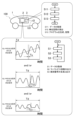
- FIG. 1 is a diagram for explaining a state identification device according to a first embodiment of the present invention.
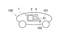
- FIG. 2 is a diagram for explaining a state identification device according to a second embodiment of the present invention.
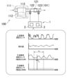
- FIG. 3 is a diagram for explaining a state identification device according to a third embodiment of the present invention.
- FIG. 4(a) is a graph showing the Mahalanobis distance when the catalyst is normal, and FIG. 4(b) is a histogram of the Mahalanobis distance of FIG. 4(a).
- FIG. 5 is an enlarged partial graph of the graph in FIG.
- FIG. 6(a) is a graph showing the Mahalanobis distance when the catalyst is deteriorated, and
- FIG. 6(b) is a histogram of the Mahalanobis distance of FIG. 6(a).
- FIG. 7 is an enlarged partial graph of the graph in FIG.
- FIG. 8 is a diagram for explaining a state identification device according to a fourth embodiment of the present invention.
- the state identification device 1 outputs an identification signal for identifying the state of the vehicle 100 or the state of a part of the vehicle 100 based on an output signal of a sensor 101 provided in the vehicle 100, whose driving environment and driving state change, or a predetermined signal generated from the output signal of the sensor 101, in order to use the signal for controlling the vehicle 100, to notify a user, or to collect data related to the vehicle 100.
- Fig. 1 shows an example in which the state identification device 1 is provided in the vehicle 100, but the state identification device 1 may be a device that is not provided in the vehicle 100 and can communicate with a device provided in the vehicle 100.
- the output signal of the sensor 101 or the predetermined signal is a continuous vibration signal that vibrates at least in a steady state in which the driving environment and driving state do not change.
- the three graphs included in Fig. 1 show an example of a continuous vibration signal in which a fluctuation in the center of vibration occurs due to the influence of a change in at least one of the driving environment and the driving state, an example of a continuous vibration signal in which a change in the amplitude of vibration occurs due to the influence of a change in at least one of the driving environment and the driving state, and an example of a continuous vibration signal in which a disturbance in the period of vibration occurs due to the influence of a change in at least one of the driving environment and the driving state.
- the vertical axis of the three graphs included in Fig. 1 shows the output signal of the sensor 101 or a predetermined signal generated from the output signal of the sensor 101.
- the state identification device 1 has a processor 2 and a storage device 3.
- the processor 2 When a signal disturbance occurs due to the influence of at least one of a change in the driving environment and the driving state, which is at least one of a change in the center of vibration of the continuous vibration signal, a change in the amplitude of the vibration, and a disturbance in the period of the vibration, the processor 2 outputs a Mahalanobis distance reflecting a feature amount related to the change in the continuous vibration signal in which the signal disturbance has occurred, using a Mahalanobis distance output device described later that is not easily influenced by the fluctuation including both an increase and a decrease of the continuous vibration signal in which the signal disturbance has occurred during the identification period Td, and is generated based on a unit space calculated using the MT method based on data for each unit period Tu acquired multiple times during the identification period Td, and executes an identification signal output process that outputs an identification signal that identifies whether the state of the vehicle 100 or a part of the vehicle 100 is in a predetermined state or not based on
- the identification period Td is a period that is at least half the length of one period when there is no disturbance in the period of the vibration of the continuous vibration signal, and is a period of such a length that multiple times are collected during one driving cycle.
- the identification period Td in FIG. 1 is merely one example of an identification period Td.
- the unit period Tu in FIG. 1 is merely one example of a unit period Tu. According to the state identification device 1 of the first embodiment, it is possible to increase the frequency of outputting an identification signal, or to improve the design freedom of hardware resources.
- the processor 2 executes at least an identification signal output process by reading a program pre-stored in the storage device 3.
- the processor 2 performs the identification signal output process, for example, in accordance with the flowchart of Fig. 1.
- the processor 2 acquires data for each unit period Tu acquired multiple times during an identification period Td of a continuous vibration signal when signal disturbance occurs due to the influence of a change in at least one of the driving environment and the driving state.
- the processor 2 reads a Mahalanobis distance output program described later and executes processing to output a Mahalanobis distance using a Mahalanobis distance output device described later that is generated based on the unit space calculated using the MT method based on the multiple data acquired in step S1.
- the Mahalanobis distance calculated in step S2 reflects a feature amount related to the change in the continuous vibration signal where signal disturbance occurs.
- the processor 2 outputs an identification signal for identifying whether the state of the vehicle 100 or the state of a part of the vehicle 100 is a predetermined state or not, based on the Mahalanobis distance.
- the state identification device 1 of the first embodiment does not output an identification signal only when a signal disturbance occurs in the continuous vibration signal, but is also capable of outputting an identification signal when no signal disturbance occurs in the continuous vibration signal. In other words, the state identification device 1 is capable of outputting an identification signal regardless of whether or not a signal disturbance occurs in the continuous vibration signal.
- the program for executing the identification signal output process stored in the storage device 3 includes a Mahalanobis distance output program for executing a process of outputting a Mahalanobis distance based on the plurality of data acquired in step S1 in step S2.
- the processor 2 functions as a Mahalanobis distance output device that outputs a Mahalanobis distance by reading the Mahalanobis distance output program stored in the storage device 3 and executing the process.
- the Mahalanobis distance output by processor 2 by loading the Mahalanobis distance output program and executing processing is such that the closer the multiple data acquired in step S1 are to the data group used to calculate the unit space, the closer the Mahalanobis distance calculated in step S2 is to 1.
- a program for executing the identification signal output process is stored in the storage device 3, and the processor 2 reads the program stored in the storage device 3 and is ready to execute the identification signal output process, thereby producing a status identification device that outputs an identification signal that identifies whether the status of the vehicle or a part of the vehicle is in a specified status or not.
- the status identification device 1 is produced as follows. First, in step S11, an external processing device provided outside the vehicle 100 acquires continuous vibration signal data for each unit period Tu acquired multiple times during the identification period Td.
- the continuous vibration signal data acquired in step S11 includes data of the continuous vibration signal in which signal disturbance has occurred.
- the data acquired in step S11 is data of the continuous vibration signal when the state of the vehicle 100 or the state of a part of the vehicle 100 is a predetermined state, or data of the continuous vibration signal when the state of the vehicle 100 or the state of a part of the vehicle 100 is not the predetermined state.
- the external processing device calculates a single unit space using the MT method based on the data for each unit period Tu acquired in step S11 during the identification period Td of the continuous vibration signal.
- the unit space calculated in step S12 is a unit space that serves as a criterion for classifying the state of the vehicle 100 or a part of the vehicle 100 as being in a specified state or not.
- step S12 corresponds to an example of a unit space calculation step of the present invention. Since the MT method itself is known, detailed explanation of the method for calculating the unit space in step S12 will be omitted. If the data acquired in step S11 is data of a continuous vibration signal when the state of the vehicle 100 or the state of a part of the vehicle 100 is a predetermined state, the unit space calculated in step S12 is a unit space corresponding to the state of the vehicle 100 or the state of a part of the vehicle 100 being the predetermined state.
- the Mahalanobis distance calculated in step S2 is close to 1 when the state of the vehicle 100 or the state of the part of the vehicle 100 is the predetermined state, and is significantly larger than 1 when the state of the vehicle 100 or the state of the part of the vehicle 100 is not the predetermined state.
- the unit space calculated in step S12 is a unit space corresponding to the state of the vehicle 100 or the state of a part of the vehicle 100 not being a predetermined state.
- the Mahalanobis distance calculated in step S2 is close to 1 when the state of the vehicle 100 or the state of a part of the vehicle 100 is not a predetermined state, and is significantly larger than 1 when the state of the vehicle 100 or the state of a part of the vehicle 100 is a predetermined state.
- step S11 data of continuous vibration signals in various driving states of the vehicle 100 may be acquired, and in step S12, a single unit space may be calculated based on the data of the continuous vibration signals in various driving states of the vehicle 100.
- step S13 the external processing device generates a program for executing the identification signal output process and stores it in the storage device 3.
- the program for executing the identification signal output process includes a Mahalanobis distance output program.
- the Mahalanobis distance output program is generated based on the unit space calculated using the MT method in step S12. Then, the state identification device 1 is produced by the above steps S11 to S13.
- the continuous vibration signal data acquired in step S1 described above to identify whether the state of the vehicle 100 or the state of a part of the vehicle 100 is in a specified state or not, and the continuous vibration signal data acquired in step S11 to calculate the unit space are continuous vibration signal data acquired at different times.
- the state identification device 1 of the second embodiment of the present invention will be described with reference to FIG. 2.
- the second embodiment has the configuration of the first embodiment.
- the external processing device acquires, in step S11, data of the continuous vibration signal for each unit period Tu acquired multiple times during the identification period Td and data of the output signal of at least one other sensor 102 provided in the vehicle 100.
- the external processing device calculates a unit space using the MT method based on the data for each unit period Tu acquired multiple times during the identification period Td of the continuous vibration signal acquired in step S11 and the data of the output signal of the other sensor 102.
- step S13 the external processing device generates a program for executing the identification signal output process, including a Mahalanobis distance output program corresponding to this unit space, and stores it in the storage device 3 of the state identification device 1.
- the state identification device 1 in the second embodiment is produced.
- step S2 of the identification signal output process the processor 2 of the state identification device 1 of the second embodiment reads the Mahalanobis distance output program stored in the storage device 3 and executes the process, thereby outputting the Mahalanobis distance using a Mahalanobis distance output device generated based on a unit space calculated using the MT method based on data for each unit period Tu acquired multiple times during the identification period Td of the continuous vibration signal, which is either the output signal of the sensor 101 or a predetermined signal generated from the output signal of the sensor 101, and data of the output signal of at least one other sensor 102 provided in the vehicle 100. Then, in step S3, the processor 2 outputs the identification signal based on the Mahalanobis distance.
- the continuous vibration signal which is either the output signal of the sensor 101 or the predetermined signal generated from the output signal of the sensor 101, is referred to as a first continuous vibration signal.
- Calculating the unit space using the MT method based on the data for each unit period Tu acquired multiple times during the identification period Td of the first continuous vibration signal and the data of the output signal of at least one other sensor 102 may be calculating the unit space using the MT method based on the data for each unit period Tu acquired multiple times during the identification period Td of the first continuous vibration signal and the data of the output signal itself of at least one other sensor 102.
- outputting the Mahalanobis distance using a Mahalanobis distance output device generated based on the unit space calculated using the MT method based on the data for each unit period Tu acquired multiple times during the identification period Td of the first continuous vibration signal and the data of the output signal of at least one other sensor 102 is outputting the Mahalanobis distance using a Mahalanobis distance output device generated based on the unit space calculated using the MT method based on the data for each unit period Tu acquired multiple times during the identification period Td of the first continuous vibration signal and the data of the output signal itself of at least one other sensor 102.
- Calculating the unit space using the MT method based on the data for each unit period Tu acquired multiple times during the identification period Td of the first continuous vibration signal and the data of the output signal of at least one other sensor 102 may be calculating the unit space using the MT method based on the data for each unit period Tu acquired multiple times during the identification period Td of the first continuous vibration signal and the data of the other signal generated from the output signal of at least one other sensor 102.
- outputting the Mahalanobis distance using a Mahalanobis distance output device generated based on the unit space calculated using the MT method based on the data for each unit period Tu acquired multiple times during the identification period Td of the first continuous vibration signal and the data of the output signal of at least one other sensor 102 is outputting the Mahalanobis distance using a Mahalanobis distance output device generated based on the unit space calculated using the MT method based on the data for each unit period Tu acquired multiple times during the identification period Td of the first continuous vibration signal and the data of the other signal generated from the output signal of at least one other sensor 102.
- the output signal of the other sensor 102 or another signal generated from the output signal of the other sensor 102 may be a second continuous vibration signal that vibrates at least in a steady state.
- the unit space may be calculated using the MT method based on data for each unit period Tu acquired multiple times during the discrimination period Td of the first continuous vibration signal and data for each unit period Tu acquired multiple times during the discrimination period Td of the second continuous vibration signal.
- step S2 of the identification signal output process when the first continuous vibration signal and the second continuous vibration signal are disturbed due to the influence of a change in at least one of the driving environment and the driving state, the processor 2 outputs a Mahalanobis distance reflecting a feature amount related to the change in the first continuous vibration signal caused by the signal disturbance and the change in the second continuous vibration signal caused by the signal disturbance using a Mahalanobis distance output device generated based on a unit space calculated using the MT method based on the data for each unit period Tu acquired multiple times during the identification period Td of the first continuous vibration signal and the data for each unit period Tu acquired multiple times during the identification period Td of the second continuous vibration signal.
- the number of the at least one other sensor 102 is one in FIG. 2, but may be multiple.
- the third embodiment has the configuration of the first embodiment.
- the state identification device 1 according to the third embodiment is an example in which the state identification device of the present invention is applied to a catalyst deterioration diagnosis device that outputs an identification signal for identifying a deteriorated state of a catalyst.
- the application of the state identification device of the present invention to a catalyst deterioration diagnosis device is not limited to the third embodiment.
- the vehicle 100 has an engine unit 111, a catalyst 121, an upstream oxygen concentration sensor 122, and a downstream oxygen concentration sensor 123.
- the downstream oxygen concentration sensor 123 corresponds to an example of the sensor 101 in the first embodiment.
- the engine unit 111 has an engine 112 and a fuel supply device (not shown) that supplies fuel to the combustion chamber 113 of the engine 112.
- the catalyst 121 purifies the exhaust gas discharged from the combustion chamber 113 of the engine 112.
- the catalyst 121 may be, for example, a three-way catalyst.
- the upstream oxygen concentration sensor 122 and the downstream oxygen concentration sensor 123 detect the oxygen concentration in the exhaust gas discharged from the combustion chamber 113.
- the upstream oxygen concentration sensor 122 is arranged upstream of the catalyst 121 in the flow direction of the exhaust gas discharged from the combustion chamber 113.
- the downstream oxygen concentration sensor 123 is arranged downstream of the catalyst 121 in the flow direction of the exhaust gas.
- the upstream oxygen concentration sensor 122 and the downstream oxygen concentration sensor 123 detect at least whether the oxygen concentration in the exhaust gas is higher than a first concentration or lower than a second concentration.
- the first concentration may be higher than or the same as the second concentration.
- Figure 3 shows an example of the relationship between the change in the output signal of the upstream oxygen concentration sensor 122, the change in the amount of fuel supplied from the fuel supply device to the combustion chamber 113, and the change in the output signal of the downstream oxygen concentration sensor 123 when the catalyst 121 is degraded and when the catalyst 121 is not degraded.
- the output signal of the upstream oxygen concentration sensor 122 is a signal that corresponds to whether the air-fuel ratio of the mixture is rich or lean.
- the output signal of the upstream oxygen concentration sensor 122 is in a rich state
- the output signal of the upstream oxygen concentration sensor 122 is in a lean state.
- a rich air-fuel ratio of the mixture refers to a state in which there is an excess of fuel relative to the target air-fuel ratio.
- a lean air-fuel ratio of the mixture refers to a state in which there is an excess of air relative to the target air-fuel ratio.
- the engine 112 is operated so that the amount of fuel supplied from the fuel supply device to the combustion chamber 113 switches between increasing and decreasing based on the timing of the switch between the rich and lean states of the output signal of the upstream oxygen concentration sensor 122. More specifically, the fuel amount is controlled so that the fuel amount switches from a decreasing state to an increasing state based on the output signal of the upstream oxygen concentration sensor 122 switching to the lean state. The fuel amount is controlled so that the fuel amount switches from an increasing state to a decreasing state based on the output signal of the upstream oxygen concentration sensor 122 switching to the rich state.
- the output signal of the downstream oxygen concentration sensor 123 differs depending on whether the catalyst 121 is normal or deteriorated. When the catalyst 121 is normal, the output signal of the downstream oxygen concentration sensor 123 hardly changes. When the catalyst 121 is normal and at least the operating environment and operating state are in a steady state without change, the output signal of the downstream oxygen concentration sensor 123 is basically maintained in a first state indicating that the oxygen concentration in the exhaust gas is lower than a predetermined concentration, or a second state indicating that the oxygen concentration in the exhaust gas is higher than a predetermined concentration.
- the output signal of the downstream oxygen concentration sensor 123 may change from a state maintained in the first state to a state maintained in the second state, or from a state maintained in the second state to a state maintained in the first state. Even if at least one of the operating environment and the operating state does not change, the value of the output signal of the downstream oxygen concentration sensor 123 may be a continuous vibration signal that slightly increases and decreases while the catalyst 121 is normal and the output signal of the downstream oxygen concentration sensor 123 is maintained in the first state or the second state.
- the output signal of the downstream oxygen concentration sensor 123 may change according to the change in at least one of the operating environment and the operating state. For example, if the catalyst 121 is normal and at least one of the operating environment and the operating state changes, the output signal of the downstream oxygen concentration sensor 123 may change from the first state to the second state or from the second state to the first state. On the other hand, if the catalyst 121 is deteriorated, the output signal of the downstream oxygen concentration sensor 123 is a continuous vibration signal that vibrates according to the change in the amount of fuel supplied from the fuel supply device to the combustion chamber 113.
- the output signal of the downstream oxygen concentration sensor 123 is a continuous vibration signal.
- the shorter the period of the fuel amount during a certain period the shorter the period of the continuous vibration signal of the downstream oxygen concentration sensor 123 during that period.
- the output signal of the downstream oxygen concentration sensor 123 may become a continuous vibration signal in which the vibration period is disturbed due to the influence of the change in the operating environment and/or the operating state.
- the output signal of the downstream oxygen concentration sensor 123 may become a continuous vibration signal in which the vibration period is disturbed due to the influence of the change in the fuel amount due to the influence of the change in the operating environment and/or the operating state.
- the output signal of the downstream oxygen concentration sensor 123 may become a continuous vibration signal in which the vibration period is disturbed and the vibration amplitude is changed due to the influence of the change in the operating environment and/or the operating state.
- the external processing device calculates the unit space using the MT method based on data for each unit period Tu acquired during the identification period Td of the output signal of the downstream oxygen concentration sensor 123, which is a continuous vibration signal in which signal disturbance occurs, that is, at least one of a disturbance in the vibration period and a change in the vibration amplitude, due to the influence of at least one of a change in the operating environment and the operating state.
- the unit space calculated in step S12 in the third embodiment is a unit space that serves as a criterion for classifying whether the catalyst 121 is normal or deteriorated.
- step S13 the external processing device generates a program for executing an identification signal output process, including a Mahalanobis distance output program corresponding to this unit space, and stores it in the storage device 3 of the state identification device 1. In this way, the state identification device 1 in the third embodiment is produced.
- step S2 of the identification signal output process the processor 2 of the state identification device 1 reads the Mahalanobis distance output program stored in the storage device 3 and executes the process, thereby outputting a Mahalanobis distance reflecting a feature quantity related to the change in the continuous vibration signal in which the signal disturbance has occurred, using a Mahalanobis distance output device generated based on a unit space calculated using the MT method based on data for each unit period Tu acquired multiple times during the identification period Td of the output signal of the downstream oxygen concentration sensor 123, which is a continuous vibration signal in which signal disturbance has occurred, that is, at least one of a disturbance in the vibration period and a change in the vibration amplitude, due to the influence of at least one of a change in the driving environment and the driving state.
- the processor 2 outputs an identification signal for identifying the deteriorated state of the catalyst 121 based on the Mahalanobis distance.
- the identification signal for identifying the deteriorated state of the catalyst 121 is a signal for identifying whether the catalyst 121 is normal or deteriorated.
- the discrimination period Td is a period having a length of at least half of one period when the period of the vibration of the continuous vibration signal of the downstream oxygen concentration sensor 123 is not disturbed, and is a period of such length that a plurality of signals are collected during one driving cycle. It is assumed that the discrimination period Td is a period having a length shorter than half of one period when the period of the vibration of the continuous vibration signal of the downstream oxygen concentration sensor 123 is not disturbed.
- the discrimination period Td is a period having a length of at least half of one period when the period of the vibration of the continuous vibration signal of the downstream oxygen concentration sensor 123 is not disturbed, a characteristic that allows the deterioration state of the catalyst 121 to be determined appears in the output signal of the downstream oxygen concentration sensor during the discrimination period Td.
- the length of the discrimination period Td may be set regardless of the length of the period of the fuel amount, or may be set according to the length of the period of the fuel amount.
- the discrimination period Td may be, for example, about 1 second.
- the discrimination period Td may be, for example, about four fuel amount cycles.
- the unit period Tu may be, for example, about 10 to 30 msec.
- the processor 2 of the condition identification device 1 may use a Mahalanobis distance output device generated based on a unit space calculated using the MT method to output a Mahalanobis distance that reflects multiple types of features related to changes in the continuous vibration signal in which signal disturbance has occurred during the identification period Td.
- the external processing device may calculate the unit space based on the data of the output signal of the downstream oxygen concentration sensor 123 when the catalyst 121 is normal.
- step S2 of the identification signal output process the processor 2 outputs the Mahalanobis distance using a Mahalanobis distance output device generated based on the unit space calculated based on the data of the output signal of the downstream oxygen concentration sensor 123 when the catalyst 121 is normal.
- the external processing device may calculate the unit space based on the data of the output signal of the downstream oxygen concentration sensor 123 when the catalyst 121 is deteriorated.
- step S2 of the identification signal output process the processor 2 outputs the Mahalanobis distance using a Mahalanobis distance output device generated based on the unit space calculated based on the data of the output signal of the downstream oxygen concentration sensor 123 when the catalyst 121 is deteriorated.
- the external processing device may calculate the unit space in step S12 based on the data of the output signal of the downstream oxygen concentration sensor 123 in various operating states of the vehicle 100.
- the unit space may be calculated based on the data of the output signal of the downstream oxygen concentration sensor 123 in various operating regions of the engine 112. More specifically, for example, the unit space may be calculated based on the data of the output signal of the downstream oxygen concentration sensor 123 when the engine rotation speed is different.
- the external processing device may calculate the unit space in step S12 based on the data of the output signal of the downstream oxygen concentration sensor 123 in various operating environments of the vehicle 100.
- a normal catalyst may correspond to an example of the predetermined state in the first embodiment, and a deteriorated catalyst may correspond to an example of not being in the predetermined state in the first embodiment.
- a deteriorated catalyst may correspond to an example of the predetermined state in the first embodiment, and a normal catalyst may correspond to an example of not being in the predetermined state in the first embodiment.
- the processor 2 of the state identification device 1 may perform the identification signal output process using the output signal of the downstream oxygen concentration sensor 123 when the fuel amount is controlled, not for diagnosing the deteriorated state of the catalyst 121.
- the processor 2 of the state identification device 1 may perform the identification signal output process using the output signal of the downstream oxygen concentration sensor 123 when the fuel amount is controlled for diagnosing the deteriorated state of the catalyst 121.
- the third embodiment may or may not have the configuration of the second embodiment. If the third embodiment has the configuration of the second embodiment, the upstream oxygen concentration sensor 122 may correspond to an example of the other sensor 102 of the second embodiment.
- the processor 2 of the state identification device 1 of the third embodiment may be configured to execute, in addition to the identification signal output process of the present invention, an identification signal output process that outputs an identification signal that identifies the deteriorated state of the catalyst 121, which is different from the identification signal output process of the present invention.
- a Mahalanobis distance is output using a Mahalanobis distance output device generated based on a unit space calculated using the MT method based on a plurality of data for each unit period Tu of the output signal (continuous vibration signal) of the downstream oxygen concentration sensor 123 during a relatively long identification period Td, and an identification signal for identifying the deteriorated state of the catalyst 121 based on the Mahalanobis distance is output.
- the condition identification device 1 of the third embodiment since the identification period Td is relatively long, when the catalyst 121 is deteriorated, the output signal (continuous vibration signal) of the downstream oxygen concentration sensor 123 during the identification period Td exhibits a feature that allows identification of the deteriorated state of the catalyst 121. Therefore, by outputting the Mahalanobis distance by a Mahalanobis distance output device generated based on the unit space calculated using the MT method and outputting an identification signal that identifies the deteriorated state of the catalyst 121 based on the Mahalanobis distance, it is possible to easily output an identification signal that identifies the deteriorated state of the catalyst 121.
- a Mahalanobis distance is output by a Mahalanobis distance output device generated based on a unit space calculated using the MT method, and an identification signal for identifying (diagnosing) the deteriorated state of the catalyst 121 based on the Mahalanobis distance is output
- the process for identifying the deteriorated state of the catalyst 121 can be simplified compared to when an identification signal for identifying (diagnosing) the deteriorated state of the catalyst 121 based on the responsiveness of the downstream oxygen concentration sensor 123 is output. This makes it possible to reduce the number of development steps for the state identification device 1.
- the computational load of the processor 2 can be reduced, and the degree of freedom in designing hardware resources can be increased.
- the time required to output the identification signal can be shortened compared to when an identification signal for identifying (diagnosing) the deteriorated state of the catalyst 121 is output based on data related to the responsiveness of the downstream oxygen concentration sensor 123. This makes it possible to diagnose the deteriorated state of the catalyst 121 in real time.
- the state identification device 1 of the third embodiment outputs a Mahalanobis distance using a Mahalanobis distance output device generated based on a unit space calculated using the MT method, based on a plurality of data for each unit period Tu of the output signal of the downstream oxygen concentration sensor 123 during the identification period Td, and outputs an identification signal that identifies (diagnoses) the deteriorated state of the catalyst 121 based on the Mahalanobis distance.
- the deteriorated state of the catalyst 121 can be diagnosed without making the period and amplitude of the change in the fuel amount as large as when the deteriorated state of the catalyst 121 is diagnosed based on data related to the responsiveness of the downstream oxygen concentration sensor 123. Furthermore, when the cycle and amplitude of the change in the fuel amount are increased, the catalyst 121 needs to be large enough to purify the exhaust gas when the cycle and amplitude of the change in the fuel amount are increased. In contrast, in the third embodiment, the deterioration state of the catalyst 121 can be diagnosed without increasing the cycle and amplitude of the change in the fuel amount. This makes it possible to prevent the catalyst 121 from becoming large.
- the deterioration state of the catalyst 121 can be diagnosed without increasing the cycle and amplitude of the change in the fuel amount. This makes it possible to reduce the difference between the actual air-fuel ratio and the stoichiometric air-fuel ratio and improve the performance of the catalyst 121 in purifying exhaust gas.
- the third embodiment it is not necessary to increase the period and amplitude of the change in the fuel amount as much as when diagnosing the deteriorated state of the catalyst 121 based on data related to the responsiveness of the downstream oxygen concentration sensor 123, thereby improving the drivability of the vehicle 100.
- This effect is particularly noticeable when diagnosing the deteriorated state of the catalyst 121 without controlling the fuel amount for the purpose of diagnosing the deteriorated state of the catalyst 121.
- the diagnosable operating range of the engine 112 is limited.
- step S2 of the identification signal output process when a signal disturbance occurs in the output signal (continuous vibration signal) of the downstream oxygen concentration sensor 123 due to the influence of at least one of the changes in the operating environment and the operating state of the vehicle 100, the processor 2 of the state identification device 1 of the third embodiment outputs a Mahalanobis distance reflecting a feature amount related to the change in the continuous vibration signal in which the signal disturbance occurs, using a Mahalanobis distance output device that is not easily influenced by the fluctuation, including both increase and decrease, of the continuous vibration signal of the downstream oxygen concentration sensor 123 in the identification period Td and that is generated based on a unit space calculated using the MT method based on data for each unit period acquired multiple times during the identification period Td.
- step S3 the processor 2 outputs an identification signal for identifying (diagnosing) whether the catalyst 121 is normal or deteriorated based on the Mahalanobis distance.
- the diagnosable operating range of the engine 112 can be expanded compared to a case where the deterioration state of the catalyst 121 is diagnosed as normal or deteriorated based on data related to the responsiveness of the downstream oxygen concentration sensor 123. Therefore, the opportunities for diagnosing the deterioration state of the catalyst 121 can be increased.
- the diagnosable engine rotation speed range may be expanded to a lower speed range. As a result, for example, when the engine rotation speed range is divided into two equal parts, the deterioration state of the catalyst 121 may be diagnosed in the lower range.
- the deterioration state of the catalyst 121 may be diagnosed in the lowest speed range of the three ranges. Also, for example, when the engine rotation speed is an idling rotation speed, the deterioration state of the catalyst 121 may be diagnosed. Also, for example, the diagnosable engine rotation speed range may be expanded to a higher speed range. By expanding the diagnosable operating range of the engine 112, the vehicle speed range of the vehicle 100 that can be diagnosable can be expanded. For example, the diagnosable vehicle speed range may be expanded to a lower speed range. Thereby, for example, when the vehicle speed range is divided into two, it may be possible to diagnose the deteriorated state of the catalyst 121 in the lower range.
- the vehicle speed range when the vehicle speed range is divided into three, it may be possible to diagnose the deteriorated state of the catalyst 121 in the lowest speed range of the three ranges. Also, for example, it may be possible to diagnose the deteriorated state of the catalyst 121 at the vehicle speed when the engine rotation speed is the idling rotation speed. Also, for example, it may be possible to expand the diagnosable vehicle speed range to a higher speed range.
- the processor 2 of the state identification device 1 uses a Mahalanobis distance output device generated based on a unit space calculated using the MT method to output a Mahalanobis distance reflecting multiple types of feature quantities related to the change in the output signal (continuous vibration signal) of the downstream oxygen concentration sensor 123 during the identification period Td, and outputs a signal related to the Mahalanobis distance as an identification signal for identifying (diagnosing) the deteriorated state of the catalyst 121.
- the multiple types of feature quantities related to the change in the output signal (continuous vibration signal) of the downstream oxygen concentration sensor 123 during the identification period Td include at least the average value, maximum value and standard deviation of the amount of change acquired for each unit period Tu in the identification period Td.
- the length of the identification period Td is constant regardless of the length of the cycle of the fuel amount.
- the external processing device calculates the unit space based on the data of the output signals of the downstream oxygen concentration sensor 123 and the upstream oxygen concentration sensor 122 when the catalyst 121 is normal. Then, in step S13, the external processing device generates a program for executing the identification signal output process, including a Mahalanobis distance output program corresponding to this unit space, and stores the program in the storage device 3 of the condition identification device 1. In this way, the condition identification device 1 in this specific example is produced.
- the vehicle 100 has a multi-speed transmission (more specifically, a six-speed transmission).
- FIG. 4(a) and 6(a) show the engine speed ES, vehicle speed VS, throttle opening TP, gear position (gear stage) GP of the multi-speed transmission, output signal of the upstream oxygen concentration sensor 122, and output signal of the downstream oxygen concentration sensor 123 in one driving cycle.
- the horizontal axis of Fig. 4(a) and Fig. 6(a) includes a graph showing time.
- the throttle opening TP is the opening of the throttle valve that adjusts the amount of air supplied to the engine 112.
- the changes in the engine speed ES, vehicle speed VS, throttle opening TP, gear position GP, and output signal of the upstream oxygen concentration sensor 122 are almost the same.
- the condition identification device 1 of this specific example does not need to output the Mahalanobis distance over the entire range of one driving cycle.
- the condition identification device 1 of this specific example outputs the Mahalanobis distance for at least one identification period Td in one driving cycle to diagnose the deterioration state of the catalyst 121.
- the vertical axis of the graphs at the bottom of Figures 4(a) and 6(a) indicates the squared value of the Mahalanobis distance.
- the squared value of the Mahalanobis distance will be referred to as the Mahalanobis distance.
- the maximum value of the vertical axis of the graphs at the bottom of Figures 4(a) and 6(a) is 180.
- FIG. 4(a) is a graph when the catalyst 121 is normal.
- FIG. 4(b) is a histogram of the Mahalanobis distances of FIG. 4(a).
- the horizontal axis of FIG. 4(b) indicates the intervals of the Mahalanobis distances, and the vertical axis indicates the number of Mahalanobis distances included in each interval.
- most of the Mahalanobis distances in one driving cycle of FIG. 4(a) are values near 1.
- FIG. 5 is a partially enlarged graph of four parts of the graph of FIG. 4(a). However, the maximum value of the vertical axis showing the Mahalanobis distance in FIG. 5 is 20.
- the length of time t1 in the four graphs of FIG. 5 is the same and is multiple times the length of the identification period Td.
- the leftmost graph of the four graphs in Figure 5 shows the state of the vehicle 100 during steady operation with almost no change in its operating condition, with the output signal of the downstream oxygen concentration sensor 123 changing very little and the Mahalanobis distance being maintained at approximately 1.
- the second graph from the left shows the state when the gear position GP is changed.
- the gear position GP When the gear position GP is changed, the throttle opening TP temporarily becomes significantly smaller and the engine speed ES goes from a gently increasing state to a temporarily decreasing state.
- the output signal of the downstream oxygen concentration sensor 123 changes and the Mahalanobis distance becomes significantly larger than 1.
- the third graph from the left shows the state when the throttle valve is closed and the vehicle 100 decelerates.
- the fourth graph from the left shows a steady operation in which the operating state of the vehicle 100 remains almost unchanged, but the output signal of the downstream oxygen concentration sensor 123 does not change at all, so the Mahalanobis distance is significantly larger than 1.
- a pattern like the fourth graph from the left rarely occurs, but in order to accurately diagnose the deteriorated state of the catalyst 121 even if such a pattern occurs, the state identification device 1 may diagnose the deteriorated state of the catalyst 121 using the Mahalanobis distances of multiple identification periods Td.
- the state identification device 1 may diagnose that the catalyst 121 is deteriorated. Also, as in the second and third graphs from the left, even if the catalyst 121 is normal, if the operating state of the vehicle 100 changes significantly, the output signal of the downstream oxygen concentration sensor 123 changes significantly, and the Mahalanobis distance becomes significantly larger than 1. Therefore, the state identification device 1 may only diagnose when the operating state of the vehicle 100 does not change significantly.
- FIG. 6(a) is a graph when the catalyst 121 is deteriorated.
- FIG. 6(b) is a histogram of the Mahalanobis distance of FIG. 6(a). As shown in FIG. 6(b), most of the Mahalanobis distances in one driving cycle of FIG. 6(a) are values of 10 or more.
- FIG. 7 is a partially enlarged graph of four parts of the graph of FIG. 6(a). The maximum value of the vertical axis showing the Mahalanobis distance in FIG. 7 is 180.
- the length of time t2 in the four graphs of FIG. 7 is the same for each graph, is multiple times longer than the identification period Td, and is longer than the time t1.
- the four graphs in FIG. 7 are graphs when the operating state of the vehicle 100 satisfies the conditions for the state identification device 1 to diagnose the deterioration state of the catalyst 121. All four graphs show steady operation when the operating state of the vehicle 100 remains almost unchanged.
- the vehicle speed VS is zero
- the engine rotation speed ES is the idling rotation speed
- the average value of the Mahalanobis distance is 5. Since the average value of the Mahalanobis distance, 5, is sufficiently larger than the value 1 when the catalyst 121 is normal, the state identification device 1 can diagnose the deterioration state of the catalyst 121 even if the engine rotation speed ES is the idling rotation speed.
- the vehicle speed VS is a value within the low vehicle speed region, and the average value of the Mahalanobis distance is 29.
- the vehicle speed VS is a value within the medium vehicle speed region, which is higher than the low vehicle speed region, and the average value of the Mahalanobis distance is 90.
- the vehicle speed VS is in the high vehicle speed range, which is higher than the medium vehicle speed range, and the average Mahalanobis distance is 117. The higher the vehicle speed VS, the larger the Mahalanobis distance value.
- the length of the identification period Td is constant regardless of the length of the cycle of reversals of increase/decrease in the fuel amount. Therefore, the higher the vehicle speed VS, the more times the increase/decrease in the fuel amount reversals in the identification period Td, improving the diagnostic accuracy.
- the fourth embodiment has the configuration of the first embodiment.
- the condition identification device 1 according to the fourth embodiment is an example in which the condition identification device of the present invention is applied to a misfire diagnosis device that outputs an identification signal for identifying the presence or absence of a misfire in an engine.
- the application of the condition identification device of the present invention to a misfire diagnosis device is not limited to the fourth embodiment.
- the vehicle 100 has an engine 112 and an engine speed sensor 131.
- the engine speed sensor 131 corresponds to an example of the sensor 101 in the first embodiment.
- the engine 112 has a combustion chamber 113.
- the reference symbols of the engine 112 and the combustion chamber 113 are the same as those in the third embodiment, but the fourth embodiment may or may not have the configuration of the third embodiment.
- the engine 112 has a crankshaft 114.
- the power of the engine 112 is output from the crankshaft 114.
- the engine speed sensor 131 detects the engine speed, which is the rotation speed of the crankshaft 114.
- the output signal of the engine speed sensor 131 is a pulse signal, not a continuous vibration signal.
- the processor 2 generates a rotation speed signal indicating a change in the rotation speed of the engine 112 from the output signal of the engine speed sensor 131.
- the rotation speed signal corresponds to an example of a predetermined signal in the first embodiment.
- FIG. 8 shows an example of the change in the rotation speed signal when a misfire occurs and an example of the change in the rotation speed signal when a misfire does not occur.
- the rotation speed signal is a continuous vibration signal that vibrates in response to the timing of a specific stroke (e.g., a combustion stroke) in one cycle of the engine 112.
- a specific stroke e.g., a combustion stroke
- the center of vibration of the rotation speed signal may fluctuate due to the influence of the change in at least one of the driving environment and driving conditions. For example, when the amount of air supplied to the combustion chamber 113 increases and the vehicle speed increases, the center of vibration of the continuous vibration signal rises.
- the amplitude of the vibration of the rotation speed signal may change due to the influence of the change in at least one of the driving environment and driving conditions.
- the period of vibration of the rotation speed signal may be disrupted due to the influence of the change in at least one of the driving environment and driving conditions.
- the amplitude of the vibration of the rotation speed signal (continuous vibration signal) when a misfire (especially an intermittent misfire) occurs is greater than the amplitude of the vibration of the rotation speed signal (continuous vibration signal) when no misfire occurs.
- the external processing device calculates a unit space using the MT method based on data for each unit period Tu acquired during the identification period Td of a rotation speed signal (continuous vibration signal) in which signal disturbance occurs, which is at least one of a fluctuation in the center of vibration, a change in the amplitude of vibration, and a disturbance in the period of vibration, due to the influence of at least one change in the driving environment and the driving state.
- the unit space calculated in step S12 in the fourth embodiment is a unit space that serves as a criterion for classifying whether the engine 112 is misfiring or not.
- step S13 the external processing device generates a program for executing an identification signal output process, including a Mahalanobis distance output program corresponding to this unit space, and stores it in the storage device 3 of the state identification device 1. In this way, the state identification device 1 in the fourth embodiment is produced.
- step S2 of the identification signal output process the processor 2 of the state identification device 1 reads the Mahalanobis distance output program stored in the storage device 3 and executes the process, thereby outputting a Mahalanobis distance reflecting a feature amount related to a change in the continuous vibration signal in which a signal disturbance has occurred, using a Mahalanobis distance output device generated based on a unit space calculated using the MT method based on data for each unit period Tu of the rotation speed signal (continuous vibration signal) in which a signal disturbance has occurred. Then, in step S3, an identification signal for identifying whether a misfire has occurred or not has occurred in the engine 112 based on the Mahalanobis distance is output.
- the length of the identification period Td may be set regardless of the engine rotation speed, or may be set according to the engine rotation speed.
- the identification period Td may be, for example, a period of about 1 second.
- the unit period Tu may be, for example, a period of about 10 to 100 msec.
- the state identification device 1 of the fourth embodiment particularly outputs an identification signal for identifying whether the engine 112 is in a state in which an intermittent misfire has occurred or is not occurring.
- Misfires in engines can be classified into intermittent misfires and continuous misfires. Intermittent misfires refer to sporadic misfires, such as when a misfire occurs intermittently in one cylinder of an engine, or when a misfiring cylinder among multiple cylinders changes over time. Continuous misfires refer to when a misfire always occurs in one cylinder of an engine.
- the external processing device may calculate the unit space in step S12 based on the data of the rotation speed signal when intermittent misfire is occurring. Then, in step S2 of the identification signal output process, the Mahalanobis distance may be output using a Mahalanobis distance output device generated based on the unit space calculated based on the data of the rotation speed signal when intermittent misfire is occurring. Also, in the fourth embodiment, the state in which intermittent misfire is occurring corresponds to an example of the specified state in the first embodiment, and the state in which intermittent misfire is not occurring corresponds to an example of the specified state in the first embodiment.
- the fourth embodiment may or may not have the configuration of the second embodiment.
- a wheel speed sensor that detects the rotational speed of the wheels of the vehicle 100 may correspond to an example of the other sensor 102 of the second embodiment.
- a throttle sensor that detects the opening of a throttle valve that adjusts the amount of air supplied to the combustion chamber 113 may correspond to an example of the other sensor 102 of the second embodiment.
- the processor 2 of the state identification device 1 of the fourth embodiment may be configured to execute, in addition to the identification signal output process of the present invention, an identification signal output process that outputs an identification signal that identifies whether or not a misfire has occurred in the engine 112, which is different from the identification signal output process of the present invention.
Landscapes
- Engineering & Computer Science (AREA)
- Automation & Control Theory (AREA)
- Mechanical Engineering (AREA)
- Transportation (AREA)
- Chemical & Material Sciences (AREA)
- Human Computer Interaction (AREA)
- General Engineering & Computer Science (AREA)
- Combustion & Propulsion (AREA)
- Physics & Mathematics (AREA)
- General Physics & Mathematics (AREA)
- Mathematical Physics (AREA)
- Chemical Kinetics & Catalysis (AREA)
- Measurement Of Mechanical Vibrations Or Ultrasonic Waves (AREA)
Abstract
Description
ビークルの制御に利用するか、利用者に報知するか、または、前記ビークルに関するデータを収集するために、運転環境と運転状態が変化する前記ビークルに設けられたセンサの出力信号または前記センサの出力信号から生成される所定信号に基づいて前記ビークルの状態または前記ビークルの一部分の状態が所定状態であるか前記所定状態でないかを識別する識別信号を出力する状態識別装置を生産する方法であって、
前記センサの出力信号または前記所定信号が、少なくとも前記ビークルの運転環境と運転状態が変化しない定常状態において振動する連続振動信号であり、
前記ビークルの運転環境および運転状態の少なくとも一方の変化の影響により、前記連続振動信号に振動の中心の変動、振動の振幅の変化および振動の周期の乱れのうちの少なくとも1つである信号乱れが生じているときの前記連続振動信号のデータであって、前記連続振動信号の振動の周期の乱れが生じていないときの前記連続振動信号の1周期の半分以上の長さの期間であり、且つ、1ドライビングサイクル中に複数回収まるような長さの期間である識別期間における、前記信号乱れが生じた前記連続振動信号の、増加と減少の両方を含む変動の影響を受けにくく、且つ、前記識別期間中に複数取得される単位期間毎の前記連続振動信号のデータに基づいて、MT法を用いて前記ビークルの状態または前記ビークルの一部分の状態が前記所定状態であるか前記所定状態でないかを分類する基準となる単位空間を算出する単位空間算出工程と、前記状態識別装置に含まれ、マハラノビス距離を出力するマハラノビス距離出力器を、算出された前記単位空間に基づいて生成するマハラノビス距離出力器生成工程と、を備えている。
また、MTA法では、単位空間を算出するための計算がMT法よりも複雑である。また、MTA法では、算出された単位空間が適切であるか否かの検証がMT法よりも複雑である。
例えば、単位空間を算出する際には、単位空間を算出するための特徴量を選択する。MT法では、単位空間の算出に逆行列を用いており、単位空間のマハラノビス距離が1となるように単位空間を算出する。MT法では、単位空間の算出に逆行列を用いていることにより、単位空間の算出時に計算上の制約がある。単位空間の算出時の計算上の制約とは、標準偏差が0の特徴量が含まれていると単位空間を算出できないという制約、単位空間サンプル数が特徴量の数よりも少ないと単位空間を算出できないという制約、および、特徴量の間に多重共線性があると単位空間を算出できないという制約である。そのため、MT法により単位空間を算出する際には、選択した特徴量が、標準偏差が0の特徴量、または、特徴量の間に多重共線性がある複数の特徴量を含んでいると、上記計算上の制約により単位空間の算出ができない。その結果、選択した特徴量が適切でなかったことを把握して、特徴量を選択し直すことができる。
これに対して、MTA法では、単位空間の算出に余因子行列を用いており、単位空間の算出時に得られるマハラノビス距離(アジョイントマハラノビス距離)が1であるとは限らない。MTA法では、単位空間の算出に余因子行列を用いているため、単位空間の算出時の計算上の制約がMT法よりも緩和されている。そのため、MTA法により単位空間を算出する際には、選択した特徴量が、標準偏差が0の特徴量、または、特徴量の間に多重共線性がある複数の特徴量を含んでいても、単位空間の算出ができてしまうことがある。そして、この場合には、単位空間が算出された後の、算出された単位空間に基づいて、ビークルの状態またはビークルの一部分の状態が所定状態であるか所定状態でないかを十分に識別することができるか否かを検証する段階まで、選択した特徴量が適切でなかったことを把握できないことがある。
また、RT法は、単位空間を複数設定して3以上の状態のいずれであるかを判定することに適した方法であり、単位空間を1つだけ設定することも可能である。しかし、本構成の状態識別装置では、ビークルの状態またはビークルの一部分の状態が所定状態であるか所定状態でないかを識別することができればよい。そのため、ビークルの状態またはビークルの一部分の状態が所定状態であるか所定状態でないかを識別する識別信号を出力する状態識別装置を生産する際に、あえて、単位空間を複数設定する場合に適しているが、単位空間を算出するための計算が複雑で、算出された単位空間が適切であるか否かの検証が複雑なRT法を用いて単位空間を算出し、算出された単位空間に基づいてマハラノビス距離出力器を生成することによって、マハラノビス距離出力器を複雑にする必要がない。
前記マハラノビス距離出力器生成工程において、信号水準を使用せずに前記マハラノビス距離出力器を生成する。
前記単位空間算出工程において、単一の単位空間を算出する。
前記単位空間算出工程において、MT法を用いて、前記識別期間における、前記信号乱れが生じた前記連続振動信号の前記単位期間毎のデータと、前記ビークルに設けられた少なくとも1つの他のセンサから出力された信号のデータとに基づいて、前記単位空間を算出する。
前記単位空間算出工程において、
前記ビークルの状態または前記ビークルの一部分の状態が前記所定状態であるときの前記連続振動信号のデータ、または、前記ビークルの状態または前記ビークルの一部分の状態が前記所定状態でないときの前記連続振動信号のデータに基づいて、MT法を用いて前記単位空間を算出する。
前記ビークルが、エンジンと、前記エンジンから排出された排ガスを浄化するための触媒とを備え、前記単位空間算出工程において、MT法を用いて、前記触媒が正常であるか前記触媒が劣化しているかを分類する基準となる前記単位空間を算出する。
前記ビークルが、エンジンを備え、前記単位空間算出工程において、MT法を用いて、前記エンジンにおいて失火が生じているか失火が生じていないかを分類する基準となる前記単位空間を算出する。
ビークルの制御に利用するか、利用者に報知するか、または、前記ビークルに関するデータを収集するために、運転環境と運転状態が変化する前記ビークルに設けられたセンサの出力信号または前記センサの出力信号から生成される所定信号に基づいてビークルの状態またはビークルの一部分の状態が所定状態であるか前記所定状態でないかを識別する識別信号を出力する状態識別装置であって、センサの出力信号または前記所定信号が、少なくとも前記ビークルの運転環境と運転状態が変化しない定常状態において振動する連続振動信号であり、前記ビークルの運転環境および運転状態の少なくとも一方の変化の影響により、前記連続振動信号に、振動の中心の変動、振動の振幅の変化および振動の周期の乱れのうちの少なくとも1つである信号乱れが生じているときに、前記連続振動信号に振動の周期の乱れが生じていないときの前記連続振動信号の1周期の半分以上の長さの期間であって、且つ、1ドライビングサイクル中に複数回収まるような長さの期間である識別期間における、前記信号乱れが生じた前記連続振動信号の、増加と減少の両方を含む変動の影響を受けにくく、且つ、前記識別期間中に複数取得される単位期間毎のデータに基づいて、MT法を用いて算出された単位空間に基づいて生成されたマハラノビス距離出力器を用いて、前記信号乱れが生じた前記連続振動信号の変化に関する特徴量が反映されたマハラノビス距離を出力し、前記マハラノビス距離に基づいて前記ビークルの状態または前記ビークルの一部分の状態が前記所定状態であるか前記所定状態でないかを識別する前記識別信号を出力する、識別信号出力処理を少なくとも実行するプロセッサを有する。
また、本構成において、識別期間における、信号乱れが生じた連続振動信号の、識別期間中に複数取得される単位期間毎のデータに基づいて、MT法を用いて算出された単位空間に基づいて生成されたマハラノビス距離出力器を用いてマハラノビス距離を出力し、マハラノビス距離に基づいてビークルの状態またはビークルの一部分の状態を識別する識別信号を出力するため、連続振動信号を詳細に分析するための複雑な演算処理を行う必要がなく、識別信号を容易に生成することができる。それにより、状態識別装置のハードウェアリソースの設計自由度を向上できる。また、本構成において、上記のように連続振動信号を詳細に分析するための複雑な演算処理を行う必要がなく、識別信号を容易に生成することができるため、ビークルの状態またはビークルの一部分の状態が所定状態であるか所定状態でないかをリアルタイムで識別することができる。
前記プロセッサは、前記識別信号出力処理において、前記ビークルの運転環境および運転状態の少なくとも一方の変化の影響により、前記連続振動信号に前記信号乱れが生じているときに、前記識別期間における、前記信号乱れが生じた前記連続振動信号の前記単位期間毎のデータと、前記ビークルに設けられた少なくとも1つの他のセンサから出力された信号のデータとに基づいて、MT法を用いて算出された単位空間に基づいて生成されたマハラノビス距離出力器を用いて、前記信号乱れが生じた前記連続振動信号の変化に関する特徴量が反映されたマハラノビス距離を出力し、マハラノビス距離に基づいて前記ビークルの状態またはビークルの一部分の状態が前記所定状態であるか前記所定状態でないかを識別する前記識別信号を出力する。
前記プロセッサは、前記識別信号出力処理において、前記ビークルの状態または前記ビークルの一部分の状態が前記所定状態であるときの前記連続振動信号のデータに基づいてMT法を用いて算出された単位空間に基づいて生成されたマハラノビス距離出力器、または、前記ビークルの状態または前記ビークルの一部分の状態が前記所定状態でないときの前記連続振動信号のデータに基づいてMT法を用いて算出された単位空間に基づいて生成されたマハラノビス距離出力器を用いて、マハラノビス距離を出力する。
前記ビークルが、エンジンと、前記エンジンから排出された排ガスを浄化するための触媒とを備え、前記識別信号が、前記触媒が正常であるか前記触媒が劣化しているかを識別する信号を含む。
前記ビークルが、エンジンを備え、前記識別信号が、前記エンジンにおいて失火が生じているか失火が生じていないかを識別する信号を含む。
そして、このマハラノビス距離に基づいて、ビークルの状態またはビークルの一部分の状態を識別する識別信号が出力される。マハラノビス距離は、単位空間からどれだけ離れているかを示す。マハラノビス距離が1に近いほど、マハラノビス距離の算出の元となったデータが、単位空間の算出に用いたデータ群に近いことを示す。
識別信号は、マハラノビス距離そのものを示す信号であってもよいし、マハラノビス距離に基づくがマハラノビス距離そのものを示さない信号であってもよい。
識別信号が、マハラノビス距離そのものを示す信号である場合、識別信号は、例えば、マハラノビス距離の2乗の値を示す信号でもよい。マハラノビス距離が用いられる品質工学の分野においては、マハラノビス距離の2乗の値を、マハラノビス距離と称する場合がある。
識別信号がマハラノビス距離そのものを示す信号でない場合、識別信号は、例えば、マハラノビス距離に基づく、ビークルの状態またはビークルの一部分の状態が所定状態にどの程度近いのかを示す信号を含んでいてもよい。また、例えば、識別信号は、マハラノビス距離に基づく、ビークルの状態またはビークルの一部分の状態が、所定状態ではない状態にどの程度近いのかを示す信号を含んでいてもよい。プロセッサは、識別信号を出力するときに、マハラノビス距離に基づいてビークルの状態またはビークルの一部分の状態を識別した結果を示す識別信号も出力してもよい。ビークルの状態またはビークルの一部分の状態を識別した結果とは、例えば、ビークルの状態またはビークルの一部分の状態が所定状態であるか所定状態でないかという識別結果(診断結果)でもよい。
本発明および実施形態において、識別期間は1ドライビングサイクル中に複数回収まるような長さの期間である。但し、状態識別装置は、1つの識別期間の連続振動信号の単位期間毎のデータに基づいてマハラノビス距離を出力し、マハラノビス距離に基づいて識別信号を出力してもよいし、2つ以上の識別期間の連続振動信号の単位期間毎のデータに基づいてマハラノビス距離を出力し、マハラノビス距離に基づいて識別信号を出力してもよい。
信号乱れが生じた連続振動信号の変化に関する複数種類の特徴量は、信号乱れが生じた連続振動信号の識別期間における単位期間毎の値から算出される、識別期間の時間の長さに対する、信号乱れが生じた連続振動信号が特定の状態である期間の時間の長さの比率を含んでいてもよい。
但し、MT法においては計算上の制約があるため、信号乱れが生じた連続振動信号の変化に関する特徴量は、標準偏差が0でない特徴量である必要がある。また、MT法においては計算上の制約があるため、信号乱れが生じた連続振動信号の変化に関する複数種類の特徴量は、特徴量の間に多重共線性がない複数種類の特徴量である必要がある。例えば、信号乱れが生じた連続振動信号の、識別期間における単位期間毎に取得される変化量の平均値と積分値と軌跡長との間には多重共線性がある。また、例えば、信号乱れが生じた連続振動信号の、識別期間における単位期間毎に取得される変化量の分散と標準偏差との間には多重共線性がある。
本発明におよび実施形態において、状態識別装置を生産するとは、状態識別装置を作り出すことである。本発明におよび実施形態において、状態識別装置を生産する方法は、状態識別装置の生産方法であってもよい。本発明におよび実施形態において、状態識別装置を生産する方法は、状態識別装置を製造する方法であってもよい。本発明におよび実施形態において、状態識別装置を生産する方法は、状態識別装置の製造方法であってもよい。
本発明の第1実施形態の状態識別装置1について図1を参照しつつ説明する。第1実施形態の状態識別装置1は、ビークル100の制御に利用するか、利用者に報知するか、または、ビークル100に関するデータを収集するために、運転環境と運転状態が変化するビークル100に設けられたセンサ101の出力信号またはセンサ101の出力信号から生成された所定信号に基づいてビークル100の状態またはビークル100の一部分の状態を識別する識別信号を出力する。図1は、状態識別装置1がビークル100に設けられている例を示すが、状態識別装置1は、ビークル100に設けられておらず、ビークル100に設けられた装置と通信可能な装置でもよい。センサ101の出力信号または上記所定信号は、少なくとも運転環境と運転状態が変化しない定常状態において、振動する連続振動信号である。図1に含まれる3つのグラフは、運転環境および運転状態の少なくとも一方の変化の影響により、振動の中心の変動が生じた連続振動信号の例と、運転環境および運転状態の少なくとも一方の変化の影響により、振動の振幅の変化が生じた連続振動信号の例と、運転環境および運転状態の少なくとも一方の変化の影響により、振動の周期の乱れが生じた連続振動信号の例とを示す。図1に含まれる3つのグラフの縦軸は、センサ101の出力信号またはセンサ101の出力信号から生成された所定信号を示す。
続いて、プロセッサ2は、ステップS2において、後述するマハラノビス距離出力プログラムを読み込んで処理を実行することによって、ステップS1で取得された複数のデータに基づいて、MT法を用いて算出された単位空間に基づいて生成された後述するマハラノビス距離出力器を用いてマハラノビス距離を出力する。ステップS1で取得された複数のデータは、信号乱れが生じているときの連続振動信号のデータであるため、ステップS2で算出されるマハラノビス距離は、信号乱れが生じた連続振動信号の変化に関する特徴量が反映されたものである。
続いて、プロセッサ2は、ステップS3において、マハラノビス距離に基づいて、ビークル100の状態またはビークル100の一部分の状態が所定状態であるか所定状態でないかを識別する識別信号を出力する。
第1実施形態において、記憶装置3に記憶された、識別信号出力処理を実行するためのプログラムは、ステップS2において、ステップS1で取得された複数のデータに基づいてマハラノビス距離を出力する処理を実行するためのマハラノビス距離出力プログラムを含む。そして、第1実施形態において、プロセッサ2は、記憶装置3に記憶されたマハラノビス距離出力プログラムを読み込んで処理を実行することによって、マハラノビス距離を出力するマハラノビス距離出力器として機能する。
プロセッサ2がマハラノビス距離出力プログラムを読み込んで処理を実行することにより出力するマハラノビス距離は、ステップS1で取得された複数のデータが、単位空間の算出に用いたデータ群に近いほど、ステップS2で算出されるマハラノビス距離が1に近い。
まず、ビークル100の外部に設けられた外部処理装置が、ステップS11において、識別期間Td中に複数取得される単位期間Tu毎の連続振動信号のデータを取得する。ステップS11において取得される連続振動信号のデータは、信号乱れが生じた連続振動信号のデータを含む。また、ステップS11で取得されるデータは、ビークル100の状態またはビークル100の一部分の状態が所定状態であるときの連続振動信号のデータ、または、ビークル100の状態またはビークル100の一部分の状態が所定状態でないときの連続振動信号のデータである。
続いて、外部処理装置が、ステップS12において、ステップS11で取得した、連続振動信号の識別期間Td中に複数取得される単位期間Tu毎のデータに基づいて、MT法を用いて単一の単位空間を算出する。ステップS12において算出される単位空間は、ビークル100またはビークル100の一部分の状態が所定状態であるか所定状態でないかを分類する基準となる単位空間である。なお、第1実施形態において、ステップS12が本発明の単位空間算出工程の一例に相当する。MT法自体は公知のものであるため、ステップS12において単位空間を算出する方法の詳細については説明を省略する。
ステップS11で取得するデータが、ビークル100の状態またはビークル100の一部分の状態が所定状態であるときの連続振動信号のデータである場合、ステップS12で算出される単位空間は、ビークル100の状態またはビークル100の一部分の状態が所定状態であることに対応する単位空間である。そして、この場合には、ステップS2で算出されるマハラノビス距離は、ビークル100の状態またはビークル100の一部分の状態が所定状態であるときに1に近く、ビークル100の状態またはビークル100の一部分の状態が所定状態でないときに1よりも大幅に大きい。
ステップS11で取得するデータが、ビークル100の状態またはビークル100の一部分の状態が所定状態でないときの連続振動信号のデータである場合、ステップS12で算出される単位空間は、ビークル100の状態またはビークル100の一部分の状態が所定状態でないことに対応する単位空間である。そして、この場合には、ステップS2で算出されるマハラノビス距離は、ビークル100の状態またはビークル100の一部分の状態が所定状態でないときに1に近く、ビークル100の状態またはビークル100の一部分の状態が所定状態であるときに1よりも大幅に大きい。
また、ステップS11において、ビークル100の様々な運転状態における連続振動信号のデータを取得し、ステップS12において、ビークル100の様々な運転状態における連続振動信号のデータに基づいて単一の単位空間を算出してもよい。
次に、本発明の第2実施形態の状態識別装置1について図2を参照しつつ説明する。第2実施形態は、第1実施形態の構成を有する。第2実施形態において、外部処理装置は、ステップS11において、識別期間Td中に複数取得される単位期間Tu毎の連続振動信号のデータと、ビークル100に設けられた少なくとも1つの他のセンサ102の出力信号のデータとを取得する。そして、外部処理装置は、ステップS12において、ステップS11で取得した、連続振動信号の識別期間Td中に複数取得される単位期間Tu毎のデータと、他のセンサ102の出力信号のデータとに基づいて、MT法を用いて単位空間を算出する。そして、外部処理装置は、ステップS13において、この単位空間に対応するマハラノビス距離出力プログラムを含む、識別信号出力処理を実行するためのプログラムを生成して状態識別装置1の記憶装置3に記憶させる。これにより、第2実施形態において状態識別装置1が生産される。
第2実施形態の状態識別装置1のプロセッサ2は、識別信号出力処理のステップS2において、記憶装置3に記憶されたマハラノビス距離出力プログラムを読み込んで処理を実行することによって、センサ101の出力信号またはセンサ101の出力信号から生成された所定信号のいずれかである連続振動信号の識別期間Td中に複数取得される単位期間Tu毎のデータと、ビークル100に設けられた少なくとも1つの他のセンサ102の出力信号のデータとに基づいて、MT法を用いて算出された単位空間に基づいて生成されたマハラノビス距離出力器を用いてマハラノビス距離を出力する。そして、プロセッサ2はステップS3において、マハラノビス距離に基づいて識別信号を出力する。第2実施形態において、センサ101の出力信号またはセンサ101の出力信号から生成された所定信号のいずれかである連続振動信号を、第1の連続振動信号と称する。
第1の連続振動信号の識別期間Td中に複数取得される単位期間Tu毎のデータと、少なくとも1つの他のセンサ102の出力信号のデータとに基づいて、MT法を用いて単位空間を算出することは、第1の連続振動信号の識別期間Td中に複数取得される単位期間Tu毎のデータと、少なくとも1つの他のセンサ102の出力信号自体のデータとに基づいて、MT法を用いて単位空間を算出することであってもよい。この場合、第1の連続振動信号の識別期間Td中に複数取得される単位期間Tu毎のデータと、少なくとも1つの他のセンサ102の出力信号のデータとに基づいて、MT法を用いて算出された単位空間に基づいて生成されたマハラノビス距離出力器を用いてマハラノビス距離を出力することは、第1の連続振動信号の識別期間Td中に複数取得される単位期間Tu毎のデータと、少なくとも1つの他のセンサ102の出力信号自体のデータとに基づいて、MT法を用いて算出された単位空間に基づいて生成されたマハラノビス距離出力器を用いてマハラノビス距離を出力することである。
第1の連続振動信号の識別期間Td中に複数取得される単位期間Tu毎のデータと、少なくとも1つの他のセンサ102の出力信号のデータとに基づいて、MT法を用いて単位空間を算出することは、第1の連続振動信号の識別期間Td中に複数取得される単位期間Tu毎のデータと、少なくとも1つの他のセンサ102の出力信号から生成された他の信号のデータとに基づいて、MT法を用いて単位空間を算出することであってもよい。この場合には、第1の連続振動信号の識別期間Td中に複数取得される単位期間Tu毎のデータと、少なくとも1つの他のセンサ102の出力信号のデータとに基づいて、MT法を用いて算出された単位空間に基づいて生成されたマハラノビス距離出力器を用いてマハラノビス距離を出力することは、第1の連続振動信号の識別期間Td中に複数取得される単位期間Tu毎のデータと、少なくとも1つの他のセンサ102の出力信号から生成された他の信号のデータとに基づいて、MT法を用いて算出された単位空間に基づいて生成されたマハラノビス距離出力器を用いてマハラノビス距離を出力することである。
他のセンサ102の出力信号または他のセンサ102の出力信号から生成された他の信号が、少なくとも定常状態において振動する第2の連続振動信号であってもよい。この場合に、ステップS12において、運転環境および運転状態の少なくとも一方の変化の影響により、第1の連続振動信号および第2の連続振動信号に信号乱れが生じているときに、第1の連続振動信号の識別期間Td中に複数取得される単位期間Tu毎のデータと、第2の連続振動信号の識別期間Td中に複数取得される単位期間Tu毎のデータとに基づいて、MT法を用いて単位空間を算出してもよい。この場合、プロセッサ2は、識別信号出力処理のステップS2において、運転環境および運転状態の少なくとも一方の変化の影響により、第1の連続振動信号および第2の連続振動信号に信号乱れが生じているときに、第1の連続振動信号の識別期間Td中に複数取得される単位期間Tu毎のデータと、第2の連続振動信号の識別期間Td中に複数取得される単位期間Tu毎のデータとに基づいて、MT法を用いて算出された単位空間に基づいて生成されたマハラノビス距離出力器を用いて信号乱れが生じた第1の連続振動信号の変化および信号乱れが生じた第2の連続振動信号の変化に関する特徴量が反映されたマハラノビス距離を出力する。少なくとも1つの他のセンサ102の数は、図2では1つであるが、複数でもよい。
次に、本発明の第3実施形態の状態識別装置1について図3を参照しつつ説明する。第3実施形態は、第1実施形態の構成を有する。第3実施形態の状態識別装置1は、本発明の状態識別装置を、触媒の劣化状態を識別する識別信号を出力する触媒劣化診断装置に適用した一例である。但し、本発明の状態識別装置を触媒劣化診断装置に適用した例は、第3実施形態に限らない。
状態識別装置1のプロセッサ2は、識別信号出力処理のステップS2において、記憶装置3に記憶されたマハラノビス距離出力プログラムを読み込んで処理を実行することによって、運転環境および運転状態の少なくとも一方の変化の影響により振動の周期の乱れおよび振動の振幅の変化の少なくとも一方である信号乱れが生じた連続振動信号である下流酸素濃度センサ123の出力信号の、識別期間Td中に複数取得される単位期間Tu毎のデータに基づいて、MT法を用いて算出された単位空間に基づいて生成されたマハラノビス距離出力器を用いて、信号乱れが生じた連続振動信号の変化に関する特徴量が反映されたマハラノビス距離を出力する。そして、プロセッサ2は、ステップS3において、マハラノビス距離に基づいて、触媒121の劣化状態を識別する識別信号を出力する。触媒121の劣化状態を識別する識別信号は、触媒121が正常であるか触媒121が劣化しているかを識別する信号である。識別期間Tdは、下流酸素濃度センサ123の連続振動信号の振動の周期の乱れが生じていないときの1周期の半分以上の長さの期間であって、且つ、1ドライビングサイクル中に複数回収まるような長さの期間である。仮に、識別期間Tdが、下流酸素濃度センサ123の連続振動信号の振動の周期の乱れが生じていないときの1周期の半分よりも短い長さの期間であるとする。この場合、識別期間Tdに、下流酸素濃度センサ123の出力信号が第1状態から第2状態へまたは第2状態から第1状態に1回だけ変化した場合に、触媒121が劣化しているかどうかを判断することが難しい。識別期間Tdが、下流酸素濃度センサ123の連続振動信号の振動の周期の乱れが生じていないときの1周期の半分以上の長さの期間であることにより、識別期間Tdにおける下流酸素濃度センサの出力信号に、触媒121の劣化状態を判断できる特徴が現れる。識別期間Tdの長さは、燃料量の周期の長さによらずに設定されてもよく、燃料量の周期の長さに応じて設定されてもよい。識別期間Tdは、例えば、1秒程度の期間であってもよい。識別期間Tdは、例えば、燃料量の周期4つ分程度の長さの期間であってもよい。単位期間Tuは、例えば、10~30msec程度の期間であってもよい。
第3実施形態において、外部処理装置は、ステップS12において、触媒121が正常であるときの下流酸素濃度センサ123の出力信号のデータに基づいて単位空間を算出してもよい。この場合、プロセッサ2は、識別信号出力処理のステップS2において、触媒121が正常であるときの下流酸素濃度センサ123の出力信号のデータに基づいて算出された単位空間に基づいて生成されたマハラノビス距離出力器を用いてマハラノビス距離を出力する。
第3実施形態において、外部処理装置は、ステップS12において、触媒121が劣化しているときの下流酸素濃度センサ123の出力信号のデータに基づいて単位空間を算出してもよい。この場合、プロセッサ2は、識別信号出力処理のステップS2において、触媒121が劣化しているときの下流酸素濃度センサ123の出力信号のデータに基づいて算出された単位空間に基づいて生成されたマハラノビス距離出力器を用いてマハラノビス距離を出力する。
また、第3実施形態において、外部処理装置は、ステップS12において、ビークル100の様々な運転状態における下流酸素濃度センサ123の出力信号のデータに基づいて単位空間を算出してもよい。例えば、エンジン112の様々な運転領域における下流酸素濃度センサ123の出力信号のデータに基づいて単位空間を算出してもよい。より具体的には、例えば、エンジン回転速度が異なる場合の下流酸素濃度センサ123の出力信号のデータに基づいて単位空間を算出してもよい。また、外部処理装置は、ステップS12において、ビークル100の様々な運転環境における下流酸素濃度センサ123の出力信号のデータに基づいて単位空間を算出してもよい。
また、第3実施形態において、触媒が正常であることが、第1実施形態の所定状態であることの一例に相当し、触媒が劣化していることが、第1実施形態の所定状態でないことの一例に相当してもよい。あるいは、触媒が劣化していることが第1実施形態の所定状態であることの一例に相当し、触媒が正常であることが第1実施形態の所定状態でないことの一例に相当してもよい。
これに対して、第3実施形態の状態識別装置1においては、比較的長い識別期間Tdにおける下流酸素濃度センサ123の出力信号(連続振動信号)の、単位期間Tu毎の複数のデータに基づいて、MT法を用いて算出された単位空間に基づいて生成されたマハラノビス距離出力器を用いてマハラノビス距離を出力し、マハラノビス距離に基づいて触媒121の劣化状態を識別する識別信号を出力する。そのため、触媒121が劣化している場合に、運転環境および運転状態の少なくとも一方の変化の影響により下流酸素濃度センサ123の出力信号である連続振動信号に信号乱れが生じていても、触媒121の劣化状態をより精度良く識別する識別信号を出力できる。
MT法を用いて算出された単位空間に基づいて生成されたマハラノビス距離出力器によりマハラノビス距離を出力し、マハラノビス距離に基づいて触媒121の劣化状態を識別(診断)する識別信号を出力する場合には、下流酸素濃度センサ123の応答性に基づいて触媒121の劣化状態を識別(診断)する識別信号を出力する場合と比較して、触媒121の劣化状態を識別するための処理を簡単にすることができる。これにより、状態識別装置1の開発工数を少なくすることができる。また、プロセッサ2の演算負荷を低減でき、ハードウェアリソースの設計の自由度を高くすることができる。
また、MT法を用いて算出された単位空間に基づいて生成されたマハラノビス距離出力器によりマハラノビス距離を出力し、マハラノビス距離に基づいて触媒121の劣化状態を識別(診断)する識別信号を出力する場合には、下流酸素濃度センサ123の応答性に関するデータに基づいて触媒121の劣化状態を識別(診断)する識別信号を出力する場合と比較して、識別信号を出力するのに必要な時間を短くすることができる。これにより、リアルタイムで触媒121の劣化状態を診断することができる。
これに対して、第3実施形態の状態識別装置1においては、識別期間Tdにおける下流酸素濃度センサ123の出力信号の単位期間Tu毎の複数のデータに基づいて、MT法を用いて算出された単位空間に基づいて生成されたマハラノビス距離出力器を用いてマハラノビス距離を出力し、マハラノビス距離に基づいて触媒121の劣化状態を識別(診断)する識別信号を出力する。したがって、下流酸素濃度センサ123の応答性に関するデータに基づいて触媒121の劣化状態を診断するときほどは、燃料量の変化の周期および振幅を大きくしなくても触媒121の劣化状態を診断できる。
また、燃料量の変化の周期および振幅を大きくする場合には、触媒121を、燃料量の変化の周期および振幅を大きくしたときに排ガスを浄化できる程度に大きいものにする必要がある。これに対して、第3実施形態においては、燃料量の変化の周期および振幅を大きくしなくても触媒121の劣化状態を診断できる。これにより、触媒121の大型化を抑えることができる。
また、実際の空燃比と理論空燃比の差が小さいときほど触媒121による排ガスの浄化性能が高くなるが、燃料量の変化の周期および振幅を大きくする場合には、実際の空燃比と理論空燃比との差が大きくなることがある。これに対して、第3実施形態においては、燃料量の変化の周期および振幅を大きくしなくても触媒121の劣化状態を診断できる。これにより、実際の空燃比と理論空燃比との差を小さくして、触媒121による排ガスの浄化性能を高くすることができる。
また、第3実施形態においては、下流酸素濃度センサ123の応答性に関するデータに基づいて触媒121の劣化状態を診断するときほど燃料量の変化の周期および振幅を大きくする必要がないため、ビークル100のドライバビリティを向上させることができる。触媒121の劣化状態の診断のために燃料量を制御せずに、触媒121の劣化状態を診断するときには、この効果は特に顕著である。
また、第3実施形態においては、下流酸素濃度センサ123の応答性に関するデータに基づいて触媒121の劣化状態を診断するときほど触媒121の劣化状態の診断のために燃料量の変化の周期および振幅を大きくする必要がないため、触媒121の劣化状態を診断する機会を確保しやすい。
下流酸素濃度センサ123の応答性に関するデータに基づいて触媒121の劣化状態を診断する場合、診断可能なエンジン112の運転領域が制限される。一方、第3実施形態の状態識別装置1のプロセッサ2は、識別信号出力処理のステップS2において、ビークル100の運転環境および運転状態の少なくとも一方の変化の影響により下流酸素濃度センサ123の出力信号(連続振動信号)に信号乱れが生じているときに、識別期間Tdにおける下流酸素濃度センサ123の連続振動信号の、増加と減少の両方を含む変動の影響を受けにくく、且つ、識別期間Td中に複数取得される単位期間毎のデータに基づいて、MT法を用いて算出された単位空間に基づいて生成されたマハラノビス距離出力器を用いて、信号乱れが生じた連続振動信号の変化に関する特徴量が反映されたマハラノビス距離を出力する。そして、プロセッサ2は、ステップS3において、マハラノビス距離に基づいて触媒121が正常であるか触媒121が劣化しているかを識別(診断)する識別信号を出力する。それにより、下流酸素濃度センサ123の応答性に関するデータに基づいて触媒121の劣化状態が正常であるか触媒121が劣化しているかを診断する場合に比べて、診断可能なエンジン112の運転領域を広げることができる。そのため、触媒121の劣化状態を診断する機会を増やすことができる。例えば、診断可能なエンジン回転速度の領域をより低速の領域に広げることができる場合がある。それにより、例えば、エンジン回転速度の領域を2等分した場合に低い方の領域において、触媒121の劣化状態を診断することができる場合がある。また、例えば、エンジン回転速度の領域を3等分した場合に3つの領域のうち最も低速の領域において、触媒121の劣化状態を診断することができる場合がある。また、例えば、エンジン回転速度がアイドリング回転速度のときに、触媒121の劣化状態を診断することができる場合がある。また、例えば、診断可能なエンジン回転速度の領域をより高速の領域に広げることができる場合がある。診断可能なエンジン112の運転領域を広げることができることにより、診断可能なビークル100の車速領域を広げることができる。例えば、診断可能な車速領域をより低速の領域に広げることができる場合がある。それにより、例えば、車速領域を2等分した場合に低い方の領域において、触媒121の劣化状態を診断することができる場合がある。また、例えば、車速領域を3等分した場合に3つの領域のうち最も低速の領域において、触媒121の劣化状態を診断することができる場合がある。また、例えば、エンジン回転速度がアイドリング回転速度のときの車速において、触媒121の劣化状態を診断することができる場合がある。また、例えば、診断可能な車速領域をより高速の領域に広げることができる場合がある。
次に、第3実施形態の具体例の状態識別装置1について、図4(a)、図4(b)、図5、図6(a)、図6(b)および図7を用いて説明する。但し、第3実施形態の具体例は、以下に説明する具体例に限定されない。この具体例における状態識別装置1のプロセッサ2は、識別信号出力処理において、MT法を用いて算出された単位空間に基づいて生成されたマハラノビス距離出力器を用いて、識別期間Tdにおける下流酸素濃度センサ123の出力信号(連続振動信号)の変化に関する複数種類の特徴量が反映されたマハラノビス距離を出力し、触媒121の劣化状態を識別(診断)する識別信号として、マハラノビス距離に関する信号を出力する。この具体例において、識別期間Tdにおける下流酸素濃度センサ123の出力信号(連続振動信号)の変化に関する複数種類の特徴量は、識別期間Tdにおける単位期間Tu毎に取得される変化量の平均値、最大値、および標準偏差を少なくとも含む。この具体例において、識別期間Tdの長さは、燃料量の周期の長さに関わらず一定である。この具体例において、外部処理装置は、ステップS12において、触媒121が正常であるときの下流酸素濃度センサ123および上流酸素濃度センサ122の出力信号のデータに基づいて単位空間を算出する。そして、外部処理装置は、ステップS13において、この単位空間に対応するマハラノビス距離出力プログラムを含む、識別信号出力処理を実行するためのプログラムを生成して状態識別装置1の記憶装置3に記憶させる。これにより、この具体例において状態識別装置1が生産される。この具体例において、ビークル100は、多段変速機(より詳細には6段変速機)を有する。
次に、本発明の第4実施形態の状態識別装置1について図8を参照しつつ説明する。第4実施形態は、第1実施形態の構成を有する。第4実施形態の状態識別装置1は、本発明の状態識別装置を、エンジンの失火の有無を識別する識別信号を出力する失火診断装置に適用した一例である。但し、本発明の状態識別装置を失火診断装置に適用した例は、第4実施形態に限らない。
状態識別装置1のプロセッサ2は、識別信号出力処理のステップS2において、記憶装置3に記憶されたマハラノビス距離出力プログラムを読み込んで処理を実行することによって、信号乱れが生じている回転速度信号(連続振動信号)の、識別期間Td中に複数取得される単位期間Tu毎のデータに基づいて、MT法を用いて算出された単位空間に基づいて生成されたマハラノビス距離出力器を用いて、信号乱れが生じた連続振動信号の変化に関する特徴量が反映されたマハラノビス距離を出力出力する。そして、ステップS3において、マハラノビス距離に基づいて、エンジン112において失火が生じているか失火が生じていないかを識別する識別信号を出力する。識別期間Tdの長さは、エンジン回転速度によらずに設定されてもよく、エンジン回転速度に応じて設定されてもよい。識別期間Tdは、例えば、1秒程度の期間であってもよい。単位期間Tuは、例えば、10~100msec程度の期間であってもよい。第4実施形態の状態識別装置1は、特に、エンジン112において間欠失火が生じている状態であるか間欠失火が生じていない状態であるかを識別する識別信号を出力する。エンジンの失火には、間欠失火、連続失火などがある。間欠失火とは、例えばエンジンの1つの気筒において間欠的に失火が生じる、複数の気筒のうち失火が生じている気筒が時間の経過によって切り換わる等、失火が散発していることである。連続失火とは、エンジンの1つの気筒において常に失火が生じていることである。
Claims (12)
- ビークルの制御に利用するか、利用者に報知するか、または、前記ビークルに関するデータを収集するために、運転環境と運転状態が変化する前記ビークルに設けられたセンサの出力信号または前記センサの出力信号から生成される所定信号に基づいて前記ビークルの状態または前記ビークルの一部分の状態が所定状態であるか前記所定状態でないかを識別する識別信号を出力する状態識別装置を生産する方法であって、
前記センサの出力信号または前記所定信号が、少なくとも前記ビークルの運転環境と運転状態が変化しない定常状態において振動する連続振動信号であり、
前記ビークルの運転環境および運転状態の少なくとも一方の変化の影響により、前記連続振動信号に振動の中心の変動、振動の振幅の変化および振動の周期の乱れのうちの少なくとも1つである信号乱れが生じているときの前記連続振動信号のデータであって、前記連続振動信号の振動の周期の乱れが生じていないときの前記連続振動信号の1周期の半分以上の長さの期間であり、且つ、1ドライビングサイクル中に複数回収まるような長さの期間である識別期間における、前記信号乱れが生じた前記連続振動信号の、増加と減少の両方を含む変動の影響を受けにくく、且つ、前記識別期間中に複数取得される単位期間毎の前記連続振動信号のデータに基づいて、MT法を用いて前記ビークルの状態または前記ビークルの一部分の状態が前記所定状態であるか前記所定状態でないかを分類する基準となる単位空間を算出する単位空間算出工程と、
前記状態識別装置に含まれ、マハラノビス距離を出力するマハラノビス距離出力器を、算出された前記単位空間に基づいて生成するマハラノビス距離出力器生成工程と、を備えていることを特徴とする状態識別装置を生産する方法。 - 前記マハラノビス距離出力器生成工程において、
信号水準を使用せずに前記マハラノビス距離出力器を生成することを特徴とする請求項1に記載の状態識別装置を生産する方法。 - 前記単位空間算出工程において、単一の単位空間を算出することを特徴とする請求項1に記載の状態識別装置を生産する方法。
- 前記単位空間算出工程において、
前記識別期間における、前記信号乱れが生じた前記連続振動信号の前記単位期間毎のデータと、前記ビークルに設けられた少なくとも1つの他のセンサから出力された信号のデータとに基づいて、MT法を用いて前記単位空間を算出することを特徴とする請求項1~3のいずれかに記載の状態識別装置を生産する方法。 - 前記単位空間算出工程において、
前記ビークルの状態または前記ビークルの一部分の状態が前記所定状態であるときの前記連続振動信号のデータ、または、前記ビークルの状態または前記ビークルの一部分の状態が前記所定状態でないときの前記連続振動信号のデータに基づいて、MT法を用いて前記単位空間を算出することを特徴とする請求項1~4のいずれかに記載の状態識別装置を生産する方法。 - 前記ビークルが、エンジンと、前記エンジンから排出された排ガスを浄化するための触媒とを備え、
前記単位空間算出工程において、
MT法を用いて、前記触媒が正常であるか前記触媒が劣化しているかを分類する基準となる前記単位空間を算出することを特徴とする請求項1~5のいずれかに記載の状態識別装置を生産する方法。 - 前記ビークルが、エンジンを備え、
前記単位空間算出工程において、
MT法を用いて、前記エンジンにおいて失火が生じているか失火が生じていないかを分類する基準となる前記単位空間を算出することを特徴とする請求項1~6のいずれかに記載の状態識別装置を生産する方法。 - ビークルの制御に利用するか、利用者に報知するか、または、前記ビークルに関するデータを収集するために、運転環境と運転状態が変化する前記ビークルに設けられたセンサの出力信号または前記センサの出力信号から生成される所定信号に基づいてビークルの状態またはビークルの一部分の状態が所定状態であるか前記所定状態でないかを識別する識別信号を出力する状態識別装置であって、
センサの出力信号または前記所定信号が、少なくとも前記ビークルの運転環境と運転状態が変化しない定常状態において振動する連続振動信号であり、
前記ビークルの運転環境および運転状態の少なくとも一方の変化の影響により、前記連続振動信号に、振動の中心の変動、振動の振幅の変化および振動の周期の乱れのうちの少なくとも1つである信号乱れが生じているときに、
前記連続振動信号に振動の周期の乱れが生じていないときの前記連続振動信号の1周期の半分以上の長さの期間であって、且つ、1ドライビングサイクル中に複数回収まるような長さの期間である識別期間における、前記信号乱れが生じた前記連続振動信号の、増加と減少の両方を含む変動の影響を受けにくく、且つ、前記識別期間中に複数取得される単位期間毎のデータに基づいて、MT法を用いて算出された単位空間に基づいて生成されたマハラノビス距離出力器を用いて、前記信号乱れが生じた前記連続振動信号の変化に関する特徴量が反映されたマハラノビス距離を出力し、前記マハラノビス距離に基づいて前記ビークルの状態または前記ビークルの一部分の状態が前記所定状態であるか前記所定状態でないかを識別する前記識別信号を出力する、識別信号出力処理を少なくとも実行するプロセッサを有することを特徴とする状態識別装置。 - 前記プロセッサは、前記識別信号出力処理において、
前記ビークルの運転環境および運転状態の少なくとも一方の変化の影響により、前記連続振動信号に前記信号乱れが生じているときに、
前記識別期間における、前記信号乱れが生じた前記連続振動信号の前記単位期間毎のデータと、前記ビークルに設けられた少なくとも1つの他のセンサから出力された信号のデータとに基づいて、MT法を用いて算出された単位空間に基づいて生成されたマハラノビス距離出力器を用いて、前記信号乱れが生じた前記連続振動信号の変化に関する特徴量が反映されたマハラノビス距離を出力し、マハラノビス距離に基づいて前記ビークルの状態またはビークルの一部分の状態が前記所定状態であるか前記所定状態でないかを識別する前記識別信号を出力することを特徴とする請求項8に記載の状態識別装置。 - 前記プロセッサは、前記識別信号出力処理において、
前記ビークルの状態または前記ビークルの一部分の状態が前記所定状態であるときの前記連続振動信号のデータに基づいてMT法を用いて算出された単位空間に基づいて生成されたマハラノビス距離出力器、または、前記ビークルの状態または前記ビークルの一部分の状態が前記所定状態でないときの前記連続振動信号のデータに基づいてMT法を用いて算出された単位空間に基づいて生成されたマハラノビス距離出力器を用いて、マハラノビス距離を出力することを特徴とする請求項8または9に記載の状態識別装置。 - 前記ビークルが、エンジンと、前記エンジンから排出された排ガスを浄化するための触媒とを備え、
前記識別信号が、前記触媒が正常であるか前記触媒が劣化しているかを識別する信号を含むことを特徴とする請求項8~10のいずれかに記載の状態識別装置。 - 前記ビークルが、エンジンを備え、
前記識別信号が、前記エンジンにおいて失火が生じているか失火が生じていないかを識別する信号を含むことを特徴とする請求項8~11のいずれかに記載の状態識別装置。
Priority Applications (2)
| Application Number | Priority Date | Filing Date | Title |
|---|---|---|---|
| EP23907064.2A EP4640513A4 (en) | 2022-12-19 | 2023-12-19 | METHOD FOR PRODUCING A STATE RECOGNITION DEVICE AND STATE RECOGNITION DEVICE |
| US19/241,120 US20250313221A1 (en) | 2022-12-19 | 2025-06-17 | Method for producing state recognition device and state recognition device |
Applications Claiming Priority (4)
| Application Number | Priority Date | Filing Date | Title |
|---|---|---|---|
| JPPCT/JP2022/046657 | 2022-12-19 | ||
| PCT/JP2022/046657 WO2024134717A1 (ja) | 2022-12-19 | 2022-12-19 | 状態識別装置 |
| JP2023-063949 | 2023-04-11 | ||
| JP2023063949 | 2023-04-11 |
Related Child Applications (1)
| Application Number | Title | Priority Date | Filing Date |
|---|---|---|---|
| US19/241,120 Continuation-In-Part US20250313221A1 (en) | 2022-12-19 | 2025-06-17 | Method for producing state recognition device and state recognition device |
Publications (1)
| Publication Number | Publication Date |
|---|---|
| WO2024135704A1 true WO2024135704A1 (ja) | 2024-06-27 |
Family
ID=91588697
Family Applications (1)
| Application Number | Title | Priority Date | Filing Date |
|---|---|---|---|
| PCT/JP2023/045571 Ceased WO2024135704A1 (ja) | 2022-12-19 | 2023-12-19 | 状態識別装置を生産する方法および状態識別装置 |
Country Status (3)
| Country | Link |
|---|---|
| US (1) | US20250313221A1 (ja) |
| EP (1) | EP4640513A4 (ja) |
| WO (1) | WO2024135704A1 (ja) |
Citations (10)
| Publication number | Priority date | Publication date | Assignee | Title |
|---|---|---|---|---|
| JPH05321748A (ja) * | 1992-05-18 | 1993-12-07 | Honda Motor Co Ltd | 内燃機関の失火検出装置 |
| JPH0754705A (ja) * | 1993-08-19 | 1995-02-28 | Honda Motor Co Ltd | 内燃機関の失火検出装置 |
| JP2007292014A (ja) * | 2006-04-27 | 2007-11-08 | Honda Motor Co Ltd | 内燃機関の触媒劣化検知装置 |
| WO2016194953A1 (ja) | 2015-06-02 | 2016-12-08 | 株式会社デンソー | 制御装置 |
| WO2017208757A1 (ja) * | 2016-05-31 | 2017-12-07 | ヤマハ発動機株式会社 | 失火検出装置及びビークル |
| JP2020133467A (ja) * | 2019-02-18 | 2020-08-31 | トヨタ自動車株式会社 | 触媒劣化検出装置、触媒劣化検出システム、データ解析装置、内燃機関の制御装置、および中古車の状態情報提供方法 |
| WO2021019760A1 (ja) * | 2019-08-01 | 2021-02-04 | 三菱電機株式会社 | 異常診断方法、異常診断装置および異常診断プログラム |
| JP2021032115A (ja) * | 2019-08-22 | 2021-03-01 | トヨタ自動車株式会社 | 車両用学習制御システム、車両用制御装置、および車両用学習装置 |
| WO2021182584A1 (ja) | 2020-03-12 | 2021-09-16 | ヤマハ発動機株式会社 | ストラドルドビークル |
| JP2022108222A (ja) * | 2021-01-12 | 2022-07-25 | トヨタ自動車株式会社 | 車両の制御装置 |
Family Cites Families (4)
| Publication number | Priority date | Publication date | Assignee | Title |
|---|---|---|---|---|
| JP2010014065A (ja) * | 2008-07-04 | 2010-01-21 | Mitsubishi Heavy Ind Ltd | エンジンの燃焼状態判定方法および装置 |
| JP6770802B2 (ja) * | 2015-12-28 | 2020-10-21 | 川崎重工業株式会社 | プラント異常監視方法およびプラント異常監視用のコンピュータプログラム |
| JP2019190324A (ja) * | 2018-04-23 | 2019-10-31 | 株式会社デンソー | 車両用のデータ記録装置およびデータ記録方法 |
| JP7249165B2 (ja) * | 2019-02-20 | 2023-03-30 | 三菱重工業株式会社 | 監視装置、監視方法およびプログラム |
-
2023
- 2023-12-19 WO PCT/JP2023/045571 patent/WO2024135704A1/ja not_active Ceased
- 2023-12-19 EP EP23907064.2A patent/EP4640513A4/en active Pending
-
2025
- 2025-06-17 US US19/241,120 patent/US20250313221A1/en active Pending
Patent Citations (10)
| Publication number | Priority date | Publication date | Assignee | Title |
|---|---|---|---|---|
| JPH05321748A (ja) * | 1992-05-18 | 1993-12-07 | Honda Motor Co Ltd | 内燃機関の失火検出装置 |
| JPH0754705A (ja) * | 1993-08-19 | 1995-02-28 | Honda Motor Co Ltd | 内燃機関の失火検出装置 |
| JP2007292014A (ja) * | 2006-04-27 | 2007-11-08 | Honda Motor Co Ltd | 内燃機関の触媒劣化検知装置 |
| WO2016194953A1 (ja) | 2015-06-02 | 2016-12-08 | 株式会社デンソー | 制御装置 |
| WO2017208757A1 (ja) * | 2016-05-31 | 2017-12-07 | ヤマハ発動機株式会社 | 失火検出装置及びビークル |
| JP2020133467A (ja) * | 2019-02-18 | 2020-08-31 | トヨタ自動車株式会社 | 触媒劣化検出装置、触媒劣化検出システム、データ解析装置、内燃機関の制御装置、および中古車の状態情報提供方法 |
| WO2021019760A1 (ja) * | 2019-08-01 | 2021-02-04 | 三菱電機株式会社 | 異常診断方法、異常診断装置および異常診断プログラム |
| JP2021032115A (ja) * | 2019-08-22 | 2021-03-01 | トヨタ自動車株式会社 | 車両用学習制御システム、車両用制御装置、および車両用学習装置 |
| WO2021182584A1 (ja) | 2020-03-12 | 2021-09-16 | ヤマハ発動機株式会社 | ストラドルドビークル |
| JP2022108222A (ja) * | 2021-01-12 | 2022-07-25 | トヨタ自動車株式会社 | 車両の制御装置 |
Non-Patent Citations (1)
| Title |
|---|
| See also references of EP4640513A1 |
Also Published As
| Publication number | Publication date |
|---|---|
| EP4640513A1 (en) | 2025-10-29 |
| US20250313221A1 (en) | 2025-10-09 |
| EP4640513A4 (en) | 2026-04-01 |
Similar Documents
| Publication | Publication Date | Title |
|---|---|---|
| US7954364B2 (en) | Malfunction diagnosis apparatus for exhaust gas sensor and method for diagnosis | |
| JP4618220B2 (ja) | ガスセンサの組み付け状態検出方法及びガスセンサの組み付け状態検出装置 | |
| JP2007262945A (ja) | 排出ガスセンサの異常診断装置 | |
| JP5381763B2 (ja) | 空燃比検出センサ異常診断装置 | |
| JP4325701B2 (ja) | 内燃機関の制御装置 | |
| US9394823B2 (en) | O2 purge control method and vehicle exhaust system for two type catalysts | |
| JP2005188309A (ja) | スロットル系の異常判定装置 | |
| US20250313221A1 (en) | Method for producing state recognition device and state recognition device | |
| JP2011226363A (ja) | 内燃機関の異常診断装置 | |
| JP2010163932A (ja) | 内燃機関の触媒劣化診断装置 | |
| WO2024134717A1 (ja) | 状態識別装置 | |
| JP2008128080A (ja) | 内燃機関の制御装置 | |
| JP2016223415A (ja) | 内燃機関の制御装置 | |
| JP4651694B2 (ja) | 排気浄化触媒の劣化診断装置 | |
| JPH08218853A (ja) | 排気浄化触媒の劣化診断装置 | |
| US12258890B2 (en) | Catalyst deterioration diagnosis device | |
| US9523318B2 (en) | Air-fuel ratio control apparatus for internal combustion engine and method for controlling air-fuel ratio | |
| JP2024087744A (ja) | 触媒劣化診断装置 | |
| JP4301323B2 (ja) | 内燃機関の制御装置 | |
| BR102023026757B1 (pt) | Dispositivo de diagnóstico de deterioração de catalisador | |
| JP3089969B2 (ja) | 排気浄化触媒の劣化診断装置 | |
| JP5402747B2 (ja) | 内燃機関の制御装置 | |
| BR102023026757A2 (pt) | Dispositivo de diagnóstico de deterioração de catalisador | |
| JP2006177371A (ja) | 内燃機関の制御装置 | |
| JP2008215166A (ja) | 内燃機関の制御装置 |
Legal Events
| Date | Code | Title | Description |
|---|---|---|---|
| 121 | Ep: the epo has been informed by wipo that ep was designated in this application |
Ref document number: 23907064 Country of ref document: EP Kind code of ref document: A1 |
|
| WWE | Wipo information: entry into national phase |
Ref document number: 202517054187 Country of ref document: IN |
|
| WWP | Wipo information: published in national office |
Ref document number: 202517054187 Country of ref document: IN |
|
| WWE | Wipo information: entry into national phase |
Ref document number: 2023907064 Country of ref document: EP |
|
| NENP | Non-entry into the national phase |
Ref country code: DE |
|
| REG | Reference to national code |
Ref country code: BR Ref legal event code: B01A Ref document number: 112025012374 Country of ref document: BR |
|
| ENP | Entry into the national phase |
Ref document number: 2023907064 Country of ref document: EP Effective date: 20250721 |
|
| ENP | Entry into the national phase |
Ref document number: 2023907064 Country of ref document: EP Effective date: 20250721 |
|
| ENP | Entry into the national phase |
Ref document number: 2023907064 Country of ref document: EP Effective date: 20250721 |
|
| WWP | Wipo information: published in national office |
Ref document number: 2023907064 Country of ref document: EP |
|
| NENP | Non-entry into the national phase |
Ref country code: JP |
|
| ENP | Entry into the national phase |
Ref document number: 112025012374 Country of ref document: BR Kind code of ref document: A2 Effective date: 20250617 |