WO2024143182A1 - メタノール製造方法及びメタノール製造装置 - Google Patents
メタノール製造方法及びメタノール製造装置 Download PDFInfo
- Publication number
- WO2024143182A1 WO2024143182A1 PCT/JP2023/046092 JP2023046092W WO2024143182A1 WO 2024143182 A1 WO2024143182 A1 WO 2024143182A1 JP 2023046092 W JP2023046092 W JP 2023046092W WO 2024143182 A1 WO2024143182 A1 WO 2024143182A1
- Authority
- WO
- WIPO (PCT)
- Prior art keywords
- gas
- carbon dioxide
- methanol
- separation unit
- unit
- Prior art date
- Legal status (The legal status is an assumption and is not a legal conclusion. Google has not performed a legal analysis and makes no representation as to the accuracy of the status listed.)
- Ceased
Links
Images




Classifications
-
- C—CHEMISTRY; METALLURGY
- C07—ORGANIC CHEMISTRY
- C07C—ACYCLIC OR CARBOCYCLIC COMPOUNDS
- C07C29/00—Preparation of compounds having hydroxy or O-metal groups bound to a carbon atom not belonging to a six-membered aromatic ring
- C07C29/15—Preparation of compounds having hydroxy or O-metal groups bound to a carbon atom not belonging to a six-membered aromatic ring by reduction of oxides of carbon exclusively
- C07C29/151—Preparation of compounds having hydroxy or O-metal groups bound to a carbon atom not belonging to a six-membered aromatic ring by reduction of oxides of carbon exclusively with hydrogen or hydrogen-containing gases
- C07C29/1516—Multisteps
- C07C29/1518—Multisteps one step being the formation of initial mixture of carbon oxides and hydrogen for synthesis
-
- C—CHEMISTRY; METALLURGY
- C01—INORGANIC CHEMISTRY
- C01B—NON-METALLIC ELEMENTS; COMPOUNDS THEREOF; METALLOIDS OR COMPOUNDS THEREOF NOT COVERED BY SUBCLASS C01C
- C01B3/00—Hydrogen; Gaseous mixtures containing hydrogen; Separation of hydrogen from mixtures containing it; Purification of hydrogen; Reversible storage of hydrogen
- C01B3/02—Production of hydrogen; Production of gaseous mixtures containing hydrogen
- C01B3/32—Production of hydrogen; Production of gaseous mixtures containing hydrogen by reaction of gaseous or liquid organic compounds with gasifying agents, e.g. water, carbon dioxide or air
- C01B3/34—Production of hydrogen; Production of gaseous mixtures containing hydrogen by reaction of gaseous or liquid organic compounds with gasifying agents, e.g. water, carbon dioxide or air by reaction of hydrocarbons with gasifying agents
- C01B3/38—Production of hydrogen; Production of gaseous mixtures containing hydrogen by reaction of gaseous or liquid organic compounds with gasifying agents, e.g. water, carbon dioxide or air by reaction of hydrocarbons with gasifying agents using catalysts
-
- C—CHEMISTRY; METALLURGY
- C01—INORGANIC CHEMISTRY
- C01B—NON-METALLIC ELEMENTS; COMPOUNDS THEREOF; METALLOIDS OR COMPOUNDS THEREOF NOT COVERED BY SUBCLASS C01C
- C01B3/00—Hydrogen; Gaseous mixtures containing hydrogen; Separation of hydrogen from mixtures containing it; Purification of hydrogen; Reversible storage of hydrogen
- C01B3/02—Production of hydrogen; Production of gaseous mixtures containing hydrogen
- C01B3/32—Production of hydrogen; Production of gaseous mixtures containing hydrogen by reaction of gaseous or liquid organic compounds with gasifying agents, e.g. water, carbon dioxide or air
- C01B3/34—Production of hydrogen; Production of gaseous mixtures containing hydrogen by reaction of gaseous or liquid organic compounds with gasifying agents, e.g. water, carbon dioxide or air by reaction of hydrocarbons with gasifying agents
- C01B3/48—Production of hydrogen; Production of gaseous mixtures containing hydrogen by reaction of gaseous or liquid organic compounds with gasifying agents, e.g. water, carbon dioxide or air by reaction of hydrocarbons with gasifying agents followed by reaction of water vapour with carbon monoxide
-
- C—CHEMISTRY; METALLURGY
- C07—ORGANIC CHEMISTRY
- C07B—GENERAL METHODS OF ORGANIC CHEMISTRY; APPARATUS THEREFOR
- C07B61/00—Other general methods
-
- C—CHEMISTRY; METALLURGY
- C01—INORGANIC CHEMISTRY
- C01B—NON-METALLIC ELEMENTS; COMPOUNDS THEREOF; METALLOIDS OR COMPOUNDS THEREOF NOT COVERED BY SUBCLASS C01C
- C01B2203/00—Integrated processes for the production of hydrogen or synthesis gas
- C01B2203/02—Processes for making hydrogen or synthesis gas
- C01B2203/0205—Processes for making hydrogen or synthesis gas containing a reforming step
- C01B2203/0227—Processes for making hydrogen or synthesis gas containing a reforming step containing a catalytic reforming step
- C01B2203/0233—Processes for making hydrogen or synthesis gas containing a reforming step containing a catalytic reforming step the reforming step being a steam reforming step
-
- C—CHEMISTRY; METALLURGY
- C01—INORGANIC CHEMISTRY
- C01B—NON-METALLIC ELEMENTS; COMPOUNDS THEREOF; METALLOIDS OR COMPOUNDS THEREOF NOT COVERED BY SUBCLASS C01C
- C01B2203/00—Integrated processes for the production of hydrogen or synthesis gas
- C01B2203/04—Integrated processes for the production of hydrogen or synthesis gas containing a purification step for the hydrogen or the synthesis gas
- C01B2203/0465—Composition of the impurity
- C01B2203/0475—Composition of the impurity the impurity being carbon dioxide
-
- C—CHEMISTRY; METALLURGY
- C01—INORGANIC CHEMISTRY
- C01B—NON-METALLIC ELEMENTS; COMPOUNDS THEREOF; METALLOIDS OR COMPOUNDS THEREOF NOT COVERED BY SUBCLASS C01C
- C01B2203/00—Integrated processes for the production of hydrogen or synthesis gas
- C01B2203/04—Integrated processes for the production of hydrogen or synthesis gas containing a purification step for the hydrogen or the synthesis gas
- C01B2203/0465—Composition of the impurity
- C01B2203/048—Composition of the impurity the impurity being an organic compound
-
- C—CHEMISTRY; METALLURGY
- C01—INORGANIC CHEMISTRY
- C01B—NON-METALLIC ELEMENTS; COMPOUNDS THEREOF; METALLOIDS OR COMPOUNDS THEREOF NOT COVERED BY SUBCLASS C01C
- C01B2203/00—Integrated processes for the production of hydrogen or synthesis gas
- C01B2203/06—Integration with other chemical processes
- C01B2203/061—Methanol production
-
- C—CHEMISTRY; METALLURGY
- C01—INORGANIC CHEMISTRY
- C01B—NON-METALLIC ELEMENTS; COMPOUNDS THEREOF; METALLOIDS OR COMPOUNDS THEREOF NOT COVERED BY SUBCLASS C01C
- C01B2203/00—Integrated processes for the production of hydrogen or synthesis gas
- C01B2203/08—Methods of heating or cooling
- C01B2203/0805—Methods of heating the process for making hydrogen or synthesis gas
- C01B2203/0811—Methods of heating the process for making hydrogen or synthesis gas by combustion of fuel
- C01B2203/0827—Methods of heating the process for making hydrogen or synthesis gas by combustion of fuel at least part of the fuel being a recycle stream
-
- C—CHEMISTRY; METALLURGY
- C01—INORGANIC CHEMISTRY
- C01B—NON-METALLIC ELEMENTS; COMPOUNDS THEREOF; METALLOIDS OR COMPOUNDS THEREOF NOT COVERED BY SUBCLASS C01C
- C01B2203/00—Integrated processes for the production of hydrogen or synthesis gas
- C01B2203/10—Catalysts for performing the hydrogen forming reactions
- C01B2203/1041—Composition of the catalyst
- C01B2203/1047—Group VIII metal catalysts
- C01B2203/1052—Nickel or cobalt catalysts
- C01B2203/1058—Nickel catalysts
-
- C—CHEMISTRY; METALLURGY
- C01—INORGANIC CHEMISTRY
- C01B—NON-METALLIC ELEMENTS; COMPOUNDS THEREOF; METALLOIDS OR COMPOUNDS THEREOF NOT COVERED BY SUBCLASS C01C
- C01B2203/00—Integrated processes for the production of hydrogen or synthesis gas
- C01B2203/12—Feeding the process for making hydrogen or synthesis gas
- C01B2203/1258—Pre-treatment of the feed
- C01B2203/1264—Catalytic pre-treatment of the feed
- C01B2203/127—Catalytic desulfurisation
-
- C—CHEMISTRY; METALLURGY
- C01—INORGANIC CHEMISTRY
- C01B—NON-METALLIC ELEMENTS; COMPOUNDS THEREOF; METALLOIDS OR COMPOUNDS THEREOF NOT COVERED BY SUBCLASS C01C
- C01B2203/00—Integrated processes for the production of hydrogen or synthesis gas
- C01B2203/14—Details of the flowsheet
- C01B2203/148—Details of the flowsheet involving a recycle stream to the feed of the process for making hydrogen or synthesis gas
Definitions
- methanol is synthesized from synthesis gas obtained by steam reforming the raw material natural gas (main component methane).
- the steam reforming reaction is an endothermic reaction, and in order to maintain a temperature suitable for the reaction (about 1000°C), it is necessary to supply energy by burning a large amount of fuel, which results in the emission of a large amount of carbon dioxide.
- One method for reducing the amount of carbon dioxide emitted is, for example, a method of capturing carbon dioxide from combustion exhaust gas (post-combustion carbon dioxide capture).
- Patent Document 3 discloses that in order to improve the stoichiometric value of the feed supplied to the methanol reactor, a portion of the reformed gas stream is passed through a shift reactor, and the resulting gas is then passed through a hydrogen separation device to combine the hydrogen with the reformed gas stream and adjust the M value of the reformed gas stream, thereby achieving a significant reduction in the amount of natural gas consumed in the production of synthetic gas.
- Patent Document 1 perhaps because the focus is on reducing carbon dioxide, it cannot be said that the gas flow supplied to the methanol synthesis reactor is sufficiently adjusted to have a gas composition suitable for methanol synthesis.
- Patent Document 4 discloses that reformed gas is passed through a shift reactor to simultaneously produce hydrogen and methanol, but the gas composition is not sufficiently adjusted to be suitable for methanol synthesis. In addition, the reduction in carbon dioxide emissions from the entire system is also not sufficient.
- the present invention has been made in consideration of the above circumstances, and aims to provide a method for producing methanol using natural gas as a raw material, which has low carbon dioxide emissions per unit of methanol produced and an excellent carbon yield.
- the present invention is as follows.
- the present invention provides a method for producing methanol that has low carbon dioxide emissions per unit of methanol produced and has an excellent carbon yield.
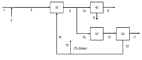
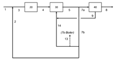
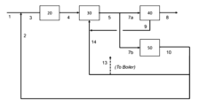
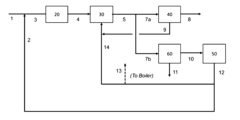
- the methanol production method of this embodiment will be described below using the methanol production apparatus of Figures 1 to 4. However, the methanol production method of this embodiment is not limited to the embodiment using the production apparatus of Figures 1 to 4.
- the hydrogen-containing gas is not particularly limited, but may be, for example, the carbon dioxide separation unit off-gas 12, the methane separation unit off-gas 16 shown in FIG. 4, or hydrogen produced outside the system.
- step (C) the reaction mixture obtained by the reaction is cooled and then gas-liquid separated, thereby obtaining methanol in the liquid phase and obtaining unreacted gas in the gas phase.
- a method for gas-liquid separation a conventionally known method can be used, and is not particularly limited, but for example, a high-pressure separator can be used.
- a portion of the reformed gas does not mean 100 mol% of the reformed gas.
- the molar flow rate of the reformed gas used in step (C) as a portion of the reformed gas is preferably 50 to 95 mol%, and more preferably 60 to 90 mol%, of the molar flow rate of the reformed gas obtained in step (A) described above.
- the molar flow rate of the reformed gas used in step (C) is 95 mol% or less, there is a tendency for the reduction of carbon dioxide emissions to be excellent, and when it is 50 mol% or more, there is a tendency for the methanol production volume to be excellent.
- carbon yield means the ratio of the molar flow rate of methanol produced in the methanol synthesis unit to the total amount of the molar flow rate of carbon monoxide and the molar flow rate of carbon dioxide contained in the reformed gas supplied to the methanol synthesis unit.
- the reaction temperature is controlled by indirect heat exchange with pressurized boiling water to obtain saturated vapor (steam).
- the boiling water circulates between the steam drum and the shell side of the reactor, and steam is recovered from the steam drum.
- the steam obtained in this synthesis system is preferably used as a heat source for the purification process of the methanol solution downstream of the synthesis process.
- the pressurized boiling water is preferably at a temperature of 220°C to 260°C.
- an adiabatic reactor When an adiabatic reactor is used, it has one or more catalyst layers inside, and if it has two or more layers, the reaction temperature is controlled by branching off a portion of the synthesis reactor supply gas and supplying it as a quench gas as a cooling gas for the intermediate layer, and an evaporator is installed as a heat recovery device in the reactor outlet gas to recover steam, which can also be used as a heat source for the downstream methanol solution purification process.
- the catalyst used in the synthesis is preferably a methanol synthesis catalyst containing copper and zinc atoms as essential components.
- Such catalysts are reduced from the oxide state by a reducing gas, such as hydrogen or carbon monoxide, or a mixture of these gases, thereby activating the copper and giving it catalytic activity.
- the catalyst may contain aluminum atoms and/or chromium atoms as a main third component.
- Catalysts containing copper and zinc as essential components can be prepared by known methods. Such catalysts can be prepared by the methods described, for example, in JP-B-51-44715, JP-B-2695663, JP-B-6-35401, JP-A-10-272361, and JP-A-2001-205089.
- a preferred catalyst is a methanol synthesis catalyst that contains copper atoms and zinc atoms in an atomic ratio (copper/zinc) of 2.0 to 3.0, and also contains aluminum atoms.
- examples of such catalysts include, but are not limited to, a catalyst prepared by the method described in JP-A-8-299796 and a catalyst described in WO 2011/048976.
- preferred catalysts include the catalysts used in the examples and comparative examples of WO 2011/048976, for example, in Examples 2 and 3.
- the more preferred atomic ratio (copper/zinc) of copper atoms and zinc atoms in the catalyst is in the range of 2.1 to 3.0.
- a methanol synthesis catalyst containing 3 to 20 mass% alumina is even more preferred. As described above, such a catalyst is not particularly limited, but can be prepared, for example, by the method described in WO 2011/048976.
- the catalyst is prepared by a manufacturing method including, for example, a step of mixing an aqueous solution containing copper, an aqueous solution containing zinc, and an alkaline aqueous solution to produce a precipitate containing copper and zinc, a step of mixing the obtained precipitate with an alumina hydrate having a pseudoboehmite structure to obtain a mixture, and a step of molding the obtained mixture to a density of 2.0 to 3.0 g/mL.
- examples of the molding method include tableting, extrusion molding, and rolling granulation.
- the catalyst used in this embodiment is not limited to the above catalyst and the catalyst prepared by the above preparation method, and may be another catalyst having equivalent methanol synthesis activity.
- step (D) in the methanol production method of this embodiment is a step of supplying the remainder 7b of the reformed gas to a shift reaction unit 50 and carrying out a shift reaction to obtain a shift reaction gas 10.
- an unreacted gas 9 may be supplied to the shift reaction unit 50 together with the remainder 7b of the reformed gas.
- the shift reaction is a reaction in which carbon monoxide in the reformed gas is reacted with water vapor to produce a shift reaction gas containing mainly water and carbon dioxide.
- the shift reaction gas is the gas obtained by step (D) and contains water and carbon dioxide produced by the reaction of carbon monoxide and hydrogen.
- the shift reaction is preferably carried out in the presence of a catalyst
- the catalyst may be a conventionally known catalyst, and may be, but is not limited to, a transition metal oxide or platinum, for example.
- the transition metal oxide may be, but is not limited to, iron oxide (Fe 3 O 4 ).
- the remainder of the reformed gas in step (D) refers to the molar flow rate of the reformed gas obtained in step (A) excluding the reformed gas used in step (C).
- the molar flow rate of the reformed gas used in step (D) is preferably 5 to 50 mol %, and more preferably 10 to 40 mol %, of the molar flow rate of the reformed gas obtained in step (A) described above.
- the molar flow rate of the reformed gas used in step (D) is 5 mol % or more, there is a tendency for the reduction of carbon dioxide emissions to be excellent, and when it is 50 mol % or less, there is a tendency for the methanol production volume to be excellent.
- the reaction temperature for the shift reaction is preferably 400°C to 700°C, and the reaction pressure is preferably 0.5 to 2.0 MPaG.
- steam supplied from outside the system may be mixed into the shift reaction unit.
- the carbon monoxide concentration in the shift reaction gas (10) is preferably 0.01 to 1.0 mol%, and more preferably 0.01 to 0.1 mol%. This reduces the amount of carbon dioxide discharged to the outside of the system due to the combustion of carbon monoxide, and tends to reduce the amount of carbon dioxide discharged per unit of methanol produced.
- step (E) in the methanol production method of the present embodiment is a step of supplying the shift reaction gas 10 to a carbon dioxide separation unit 60 to separate carbon dioxide, thereby obtaining a carbon dioxide-rich gas 11 and a carbon dioxide separation unit off-gas 12.
- Any conventional method can be used for carbon dioxide separation, and examples include, but are not limited to, physical absorption, physical adsorption, chemical absorption, chemical adsorption, membrane separation, cryogenic separation, and electrical adsorption.
- step (E) the carbon dioxide-rich gas separated and recovered in step (E) is not emitted into the atmosphere. This makes it possible to reduce carbon dioxide emissions.
- Methods for disposing of such separated and recovered carbon dioxide-rich gas include, but are not limited to, burying it underground using the CCS method, selling it as dry ice or industrial carbon dioxide gas, and using it as a raw material for chemical products.
- the carbon dioxide separation unit off-gas obtained in step (E) mainly contains hydrogen, it may be mixed with the hydrocarbon-containing gas 1 and/or the reformed gas 5 as a hydrogen-containing gas, and may be used as a heat source for step (A) via line 14, or may be used as a heat source for a boiler via line 13.
- step (E) when the molar flow rate of carbon dioxide contained in the shift reaction gas 10 is taken as 100 mol%, the molar flow rate of carbon dioxide contained in the carbon dioxide-rich gas is preferably 80 to 100 mol%, more preferably 90 to 100 mol%, and even more preferably 95 to 99.9 mol%. This tends to further reduce carbon dioxide emissions.
- step (E) water vapor may be required when absorbing or adsorbing carbon dioxide and separating it.
- the water vapor recovered in step (A) or the water vapor generated in step (C) may be used.
- step (A) may be used in step (E), or renewable energy may be supplied from outside.
- the methanol production method of the present embodiment preferably further includes a step (F).
- the step (F) is a step of supplying the hydrocarbon-containing gas 1 to a desulfurization unit 20 to obtain a sulfur-removed gas 4 from which sulfur has been removed.
- the hydrocarbon-containing gas is a fossil fuel gas
- the step (F) is particularly required since the hydrocarbon-containing gas contains sulfur. That is, since sulfur compounds are catalytic poisons for the catalysts used in the steps (A) and (C), when the hydrocarbon-containing gas contains sulfur, it is preferable to remove the sulfur compounds in advance in the step (F).
- the methanol production method of the present embodiment preferably further includes a step (G), the details of which are not shown in Figures 1 to 4, in which purified methanol is obtained from methanol 8.
- the method for obtaining purified methanol can be any conventional method, and is not particularly limited.
- a distillation column equipped with a reboiler and a condenser can be used.
- methanol is distilled to obtain highly pure methanol from the bottom or middle of the column.
- step (G) the water vapor recovered in step (A) or the water vapor generated in step (C) may be used.
- the use of water vapor makes it possible to absorb or adsorb the fluid discharged from the top of the column. This makes it possible to further reduce carbon dioxide emissions.
- the methanol production method of the present embodiment preferably further includes a step (H), which is a step of supplying the carbon dioxide separation unit offgas 12 to a methane separation unit 70 to separate methane from the carbon dioxide separation unit offgas 12, thereby obtaining a methane-rich gas 15 and a methane separation unit offgas 16, as shown in FIG.
- the method for separating methane in step (H) can be a conventionally known method, and includes, but is not limited to, physical adsorption and membrane separation.
- the molar flow rate of methane contained in the carbon dioxide separation unit off-gas is taken as 100 mol%
- the molar flow rate of methane contained in the methane-rich gas is preferably 50 to 99 mol%, more preferably 70 to 99 mol%, and even more preferably 90 to 99 mol%. This makes it possible to reduce the amount of carbon dioxide discharged to the outside of the system due to the combustion of methane, and tends to reduce the amount of carbon dioxide discharged per unit of methanol produced.
- the methane separation unit off-gas may be used as a heat source for step (A) and/or a heat source for the boiler.
- the methane separation unit off-gas 16 mainly contains hydrogen, it may be mixed with the hydrocarbon-containing gas 1 and/or the reformed gas 5 as a hydrogen-containing gas, and may be used as a heat source for step (A) via line 14, and may be used as a heat source for a boiler via line 13.
- the method for producing methanol according to the present embodiment may include other steps, if necessary, in addition to the steps described above.
- the other steps are not particularly limited, but may include, for example, a methane recovery step in which the methane-rich gas obtained in step (H) is mixed with a hydrocarbon-containing gas.
- the methanol production apparatus of this embodiment is equipped with a reforming unit 30, a methanol synthesis unit 40, a shift reaction unit 50, and a carbon dioxide separation unit 60, and the carbon dioxide separation unit off-gas 12 obtained by the carbon dioxide separation unit 60 is used as fuel for the reforming unit 30 and/or the boiler.
- the reforming unit 30 includes a reforming reactor and may include other devices as necessary.
- the reforming reactor reacts a hydrocarbon-containing gas with steam at a predetermined temperature to generate a reformed gas containing hydrogen (H 2 ), carbon monoxide (CO) and carbon dioxide (CO 2 ) as main components, which is used for the synthesis of methanol.
- the shift reaction unit 50 includes a shift reactor and may include other equipment as necessary.
- the shift reactor causes the reformed gas to undergo a shift reaction to produce a shift reaction gas.
- the carbon dioxide separation unit 60 includes a carbon dioxide separator that separates carbon dioxide from the shift reaction gas to produce a carbon dioxide-rich gas and a carbon dioxide separation unit off-gas, and may include other equipment as necessary.
- the methanol production apparatus of this embodiment preferably further includes a desulfurization unit 20, as shown in FIG. 2.
- the desulfurization unit 20 includes a desulfurizer that removes sulfur from the hydrocarbon-containing gas, and may include other equipment as necessary.
- the methanol production apparatus of this embodiment preferably further includes a methane separation unit 70 that separates methane from the carbon dioxide separation unit off-gas. This allows for further reduction in carbon dioxide emissions.
- the catalyst used for methanol synthesis was either a catalyst prepared by the method described in Example 1 of JP-B-51-44715 (methanol synthesis catalyst A), a catalyst prepared by the method described in Example 1 of JP-A-8-299796 (methanol synthesis catalyst B), a catalyst prepared by the method described in Example 3 of WO-A-2011/048976 (methanol synthesis catalyst C), or a catalyst prepared by the method described in Comparative Example 4 of JP-A-8-299796 (methanol synthesis catalyst D). Note that the amount of catalyst used in each of the following examples and comparative examples was the same.
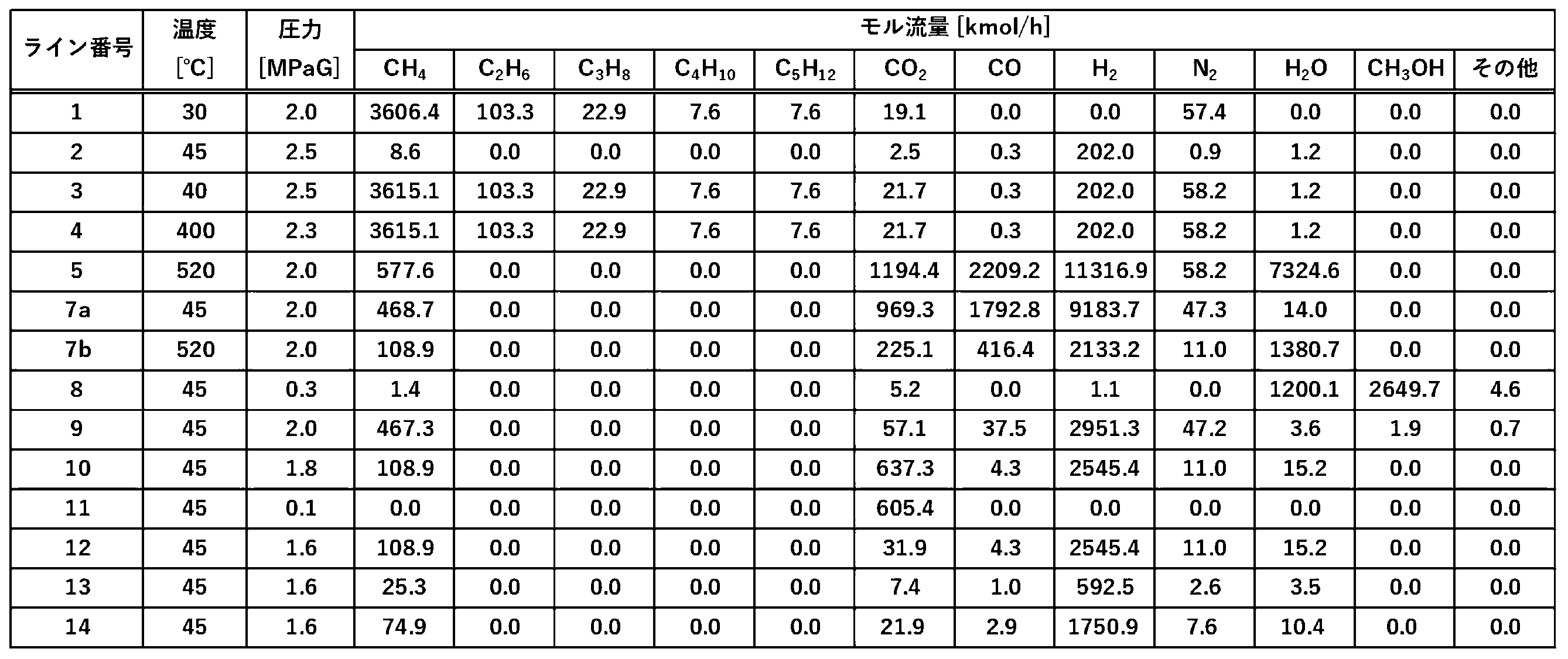
- Example 1 In Example 1, the production apparatus shown in FIG. 2 was used. Each condition was as shown in Table 1. That is, a steam reforming reaction was carried out using shale gas (CH 4 : 94.3 mol%, C 2 H 6 : 2.7 mol%, C 3 H 8 : 0.6 mol%, C 4 H 10 : 0.2 mol%, C 5 H 12 : 0.2 mol%, CO 2 : 0.5 mol%, N 2 : 1.5 mol%) as the raw material gas, and then methanol was synthesized using the synthesis gas produced thereby. Methanol synthesis catalyst C was used as a catalyst in the methanol synthesis reactor in the methanol synthesis unit.
- shale gas CH 4 : 94.3 mol%, C 2 H 6 : 2.7 mol%, C 3 H 8 : 0.6 mol%, C 4 H 10 : 0.2 mol%, C 5 H 12 : 0.2 mol%, CO 2 : 0.5 mol%, N 2 : 1.5 mol
- Example 1 The material balance for Example 1 is shown in Table 1.
- the vertical columns in Table 1 are the line numbers shown in Figure 2, and the horizontal columns are the temperature (°C), pressure (MPaG), and molar flow rate (kmol/h) of the material flowing through each line.
- Table 9 shows the methanol production amount (ton/day), carbon dioxide discharge amount (ton/day), and carbon dioxide discharge amount per unit of methanol (ton-CO 2 /ton-MeOH) obtained in Example 1.
- the methanol production amount (ton/day) in Example 1 in Table 9 is calculated by multiplying the molar flow rate (kmol/h) of methanol in line 8 in Table 1 by the molar mass of methanol (g/mol) and 24 (h).
- the carbon dioxide emission amount (ton/day) in Example 1 in Table 9 is calculated by multiplying the sum of the molar flow rates (kmol/h) of carbon dioxide in lines 9, 13, and 14 in Table 1 by the molar mass of carbon dioxide (g/mol) and 24 (h).
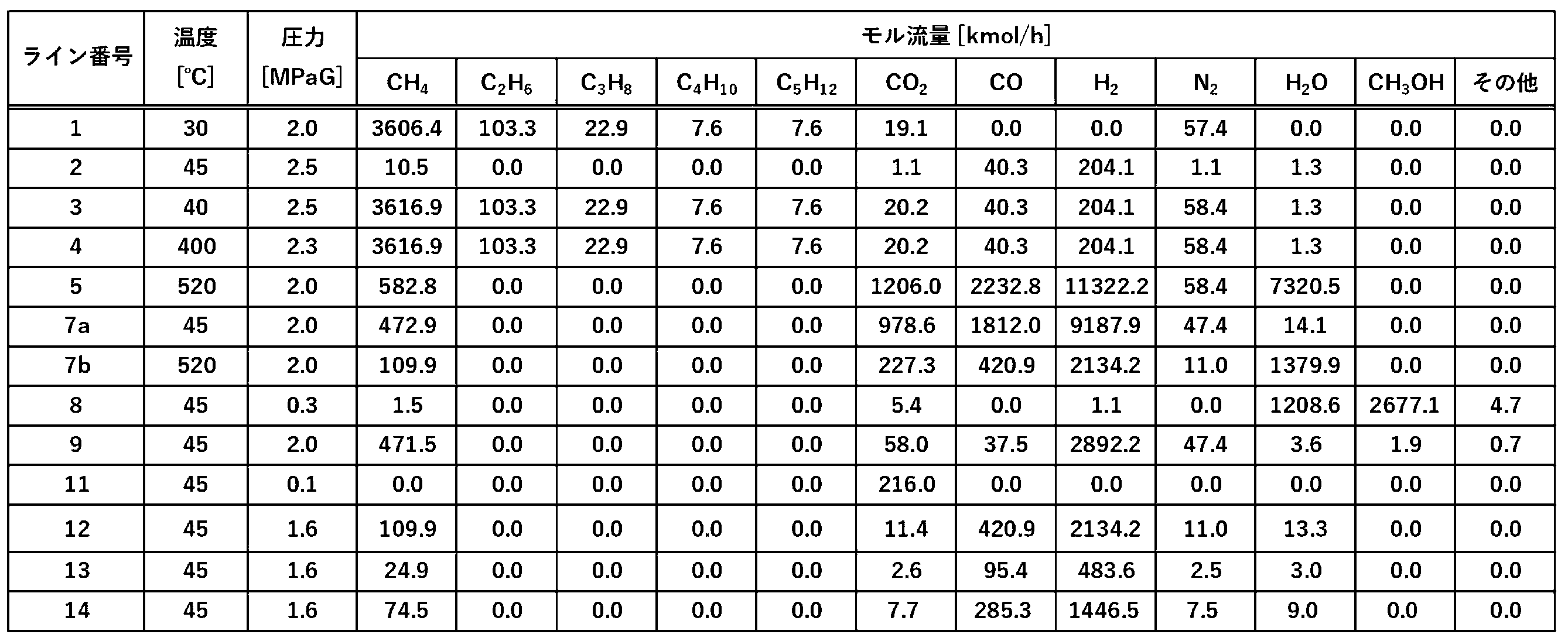
- Example 2 In Example 2, the production apparatus shown in Fig. 3 was used. Methanol synthesis was carried out under the same conditions as in Example 1, except that the line was changed as shown in Fig. 3. The material balance was as shown in Table 2.
- Table 9 shows the methanol production amount (ton/day), carbon dioxide discharge amount (ton/day), and carbon dioxide discharge amount per unit of methanol (ton-CO 2 /ton-MeOH) obtained in Example 2.
- the methanol production amount (ton/day) in Example 2 in Table 9 is calculated by multiplying the molar flow rate of methanol (kmol/h) in line 8 in Table 2 by the molar mass of methanol (g/mol) and 24 (h).
- the carbon dioxide emission amount (ton/day) in Example 2 in Table 9 is calculated by multiplying the sum of the molar flow rates (kmol/h) of carbon dioxide in lines 13 and 14 in Table 2 by the molar mass of carbon dioxide (g/mol) and 24 (h).
- Example 3 In Example 3, the production apparatus shown in Fig. 4 was used. Methanol synthesis was carried out under the same conditions as in Example 1, except that the line was changed as shown in Fig. 4 and the material balance was changed as shown in Table 3. The material balance was as shown in Table 3.
- Table 9 shows the methanol production amount (ton/day), carbon dioxide discharge amount (ton/day), and carbon dioxide discharge amount per unit of methanol (ton-CO 2 /ton-MeOH) obtained in Example 3.
- the methanol production amount (ton/day) in Example 3 in Table 9 is calculated by multiplying the molar flow rate of methanol (kmol/h) in line 8 in Table 3 by the molar mass of methanol (g/mol) and 24 (h).
- the carbon dioxide emission amount (ton/day) in Example 3 in Table 9 is calculated by multiplying the sum of the molar flow rates (kmol/h) of carbon dioxide in lines 13 and 14 in Table 3 by the molar mass of carbon dioxide (g/mol) and 24 (h).
- Table 9 shows the methanol production amount (ton/day), carbon dioxide discharge amount (ton/day), and carbon dioxide discharge amount per unit of methanol (ton-CO 2 /ton-MeOH) obtained in Comparative Example 1.
- the methanol production amount (ton/day) in Comparative Example 1 in Table 9 is calculated by multiplying the molar flow rate of methanol (kmol/h) in line 8 in Table 4 by the molar mass of methanol (g/mol) and 24 (h).
- ⁇ M value at the inlet of the methanol synthesis unit> It means the M value at the inlet of the methanol synthesis unit.
- ⁇ H 2 /CO at the inlet of the methanol synthesis unit> This refers to the ratio of the number of moles of carbon monoxide to the number of moles of hydrogen at the inlet of the methanol synthesis unit.
- ⁇ Amount of catalyst> It means the mass ratio of the catalyst amount in each Example or Comparative Example when the amount of catalyst used in the production apparatus of Example 1 is taken as 100%.
Landscapes
- Chemical & Material Sciences (AREA)
- Organic Chemistry (AREA)
- Chemical Kinetics & Catalysis (AREA)
- Health & Medical Sciences (AREA)
- General Health & Medical Sciences (AREA)
- Engineering & Computer Science (AREA)
- Combustion & Propulsion (AREA)
- Inorganic Chemistry (AREA)
- Organic Low-Molecular-Weight Compounds And Preparation Thereof (AREA)
Abstract
Description
炭化水素含有ガスを改質して改質ガスを得る工程(A)と、
前記炭化水素含有ガス及び/又は前記改質ガスに対して水素含有ガスを混合する工程(B)と、
前記改質ガスの一部を触媒存在下で反応させてメタノール及び未反応ガスを得る工程(C)と、
前記改質ガスの残部をシフト反応させてシフト反応ガスを得る工程(D)と、
前記シフト反応ガスから二酸化炭素を分離して、二酸化炭素リッチガスと二酸化炭素分離ユニットオフガスを得る工程(E)と、を含み、
前記二酸化炭素分離ユニットオフガスの少なくとも一部が、前記工程(A)及び/又はボイラーの燃料として用いられる、
メタノール製造方法。
[2]
前記炭化水素含有ガスから硫黄分を除去する工程(F)をさらに含む、
[1]に記載のメタノール製造方法。
[3]
前記メタノールから精製メタノールを得る工程(G)をさらに含む、
[1]又は[2]に記載のメタノール製造方法。
[4]
前記工程(C)に用いられる前記改質ガスのモル流量が、前記工程(A)で得られる改質ガスのモル流量に対して、50~95モル%である、
[1]~[3]のいずれかに記載のメタノール製造方法。
[5]
前記工程(C)で発生する水蒸気を、前記工程(G)及び/又は前記工程(E)で用いる、
[1]~[4]のいずれかに記載のメタノール製造方法。
[6]
前記工程(A)で回収された水蒸気を、前記工程(G)及び/又は前記工程(E)で用いる、
[1]~[5]のいずれかに記載のメタノール製造方法。
[7]
前記工程(A)で回収された熱を、前記工程(G)、及び前記工程(E)のうちの少なくともいずれかの熱源として用いる、
[1]~[6]のいずれかに記載のメタノール製造方法。
[8]
前記工程(D)は触媒存在下で行われる、
[1]~[7]のいずれかに記載のメタノール製造方法。
[9]
前記シフト反応ガス中の一酸化炭素濃度が、0.01~1.0モル%である、
[1]~[8]のいずれかに記載のメタノール製造方法。
[10]
前記シフト反応ガスが含有する二酸化炭素のモル流量を100モル%とした場合における、前記二酸化炭素リッチガスが含有する二酸化炭素のモル流量が、80~100モル%である、
[1]~[9]のいずれかに記載のメタノール製造方法。
[11]
前記未反応ガスの少なくとも一部をシフト反応ユニット及び/又は前記ボイラーへ供給する、
[1]~[10]のいずれかに記載のメタノール製造方法。
[12]
前記二酸化炭素分離ユニットオフガスからメタンを分離して、メタンリッチガス及びメタン分離ユニットオフガスを得る工程(H)をさらに含み、
前記メタン分離ユニットオフガスが、前記工程(A)及び/又は前記ボイラーの燃料に供給される、
[1]~[11]のいずれかに記載のメタノール製造方法。
[13]
前記二酸化炭素分離ユニットオフガス及び/又は前記メタン分離ユニットオフガスを、前記炭化水素含有ガス及び/又は前記改質ガスと混合させる、
[1]~[12]のいずれかに記載のメタノール製造方法。
[14]
前記二酸化炭素分離ユニットオフガスが含有するメタンのモル流量を100モル%とした場合における、前記メタンリッチガスが含有するメタンのモル流量が、50~99モル%である、
[1]~[13]のいずれかに記載のメタノール製造方法。
[15]
改質ユニットと、
メタノール合成ユニットと、
シフト反応ユニットと、
二酸化炭素分離ユニットと、を備え、
前記二酸化炭素分離ユニットにより得られる二酸化炭素分離ユニットオフガスが、前記改質ユニット及び/又はボイラーの燃料として用いられる、
メタノール製造装置。
[16]
脱硫ユニットをさらに備える、
[15]に記載のメタノール製造装置。
[17]
前記二酸化炭素分離ユニットオフガスからメタンを分離するメタン分離ユニットをさらに備える、
[15]又は[16]に記載のメタノール製造装置。
本実施形態のメタノール製造方法は、
炭化水素含有ガスを改質して改質ガスを得る工程(A)と、
前記炭化水素含有ガス及び/又は前記改質ガスに対して水素含有ガスを混合する工程(B)と、
前記改質ガスの一部を触媒存在下で反応させてメタノール及び未反応ガスを得る工程(C)と、
前記改質ガスの残部をシフト反応させてシフト反応ガスを得る工程(D)と、
前記シフト反応ガスから二酸化炭素を分離して、二酸化炭素リッチガスと二酸化炭素分離ユニットオフガスを得る工程(E)と、を含み、
前記二酸化炭素分離ユニットオフガスの少なくとも一部が、前記工程(A)及び/又はボイラーの燃料として用いられる、
メタノール製造方法である。
本実施形態のメタノール製造方法における工程(A)は、図1~4に示すとおり、炭化水素含有ガス1を改質ユニット30により改質して改質ガス5を得る工程である。具体的には、炭化水素含有ガスと水蒸気とを所定の温度において反応させ、メタノールの合成に用いられる、水素(H2)、一酸化炭素(CO)及び二酸化炭素(CO2)を主成分とする改質ガスを生成する工程である。
本実施形態のメタノール製造方法における工程(B)は、炭化水素含有ガス1及び/又は改質ガス5と水素含有ガス2とを混合する工程である。図1~4は、改質ユニット30の上流において、水素含有ガス2と炭化水素含有ガス1を混合する態様を示す。それにより、メタノール合成に適したガス組成とすることができ、また、本実施形態のメタノール製造方法が脱硫工程を含む場合、脱硫ユニット20における硫黄分除去に用いることができる。
本実施形態のメタノール製造方法における工程(C)は、図1~4に示すとおり、改質ガスの一部7aをメタノール合成ユニット40へ供給し、触媒存在下で反応させてメタノール8及び未反応ガス9を得る工程である。また、未反応ガス9は、図2に示すようにライン14のガスへ合流させてもよいし、図3及び4に示すようにライン7bのガスへ合流させてもよい。
M値=(H2モル%)/(2×COモル%+3×CO2モル%)
が、1.3~5.0であることが好ましく、1.3~3.0であることがより好ましく、1.3~2.0であることがさらに好ましく、1.3~1.5であることが特に好ましお。M値が1.3以上であると、副生成物が減少する傾向にあり、5.0以下であると、炭素収率に優れる傾向にある。
本実施形態のメタノール製造方法における工程(D)は、図1~4に示すとおり、改質ガスの残部7bをシフト反応ユニット50に供給して、シフト反応させてシフト反応ガス10を得る工程(D)である。図3及び4に示すように未反応ガス9を改質ガスの残部7bと併せてシフト反応ユニット50に供給してもよい。シフト反応は、改質ガス中の一酸化炭素を水蒸気と反応させて、主に水と二酸化炭素を含むシフト反応ガスを生成する反応である。
本実施形態のメタノール製造方法における工程(E)は、図1~4に示すとおり、シフト反応ガス10を二酸化炭素分離ユニット60に供給して、二酸化炭素を分離して、二酸化炭素リッチガス11と二酸化炭素分離ユニットオフガス12を得る工程である。
本実施形態のメタノール製造方法は工程(F)をさらに含むことが好ましい。工程(F)は、図2~4に示すとおり、炭化水素含有ガス1を脱硫ユニット20に供給して、硫黄分を除去した硫黄除去ガス4を得る工程である。炭化水素含有ガスが化石燃料ガスである場合、硫黄分を含んでいることから当該工程(F)が特に必要とされる。すなわち、硫黄化合物は工程(A)や工程(C)で用いる触媒の触媒毒になるため、炭化水素含有ガスが硫黄分を含む場合、工程(F)であらかじめ除去しておくことが好ましい。脱硫方法としては、従来公知の方法を用いることができ、特に限定されないが、例えば、吸着剤や触媒を使う乾式法、及びアミン系などの吸収液を使った湿式法が挙げられる。乾式法を用いる場合は、除去対象とする硫黄化合物の種類や採用する触媒の種類により一概にはいえないが、運転温度は0~400℃とすることができる。
本実施形態のメタノール製造方法は工程(G)をさらに含むことが好ましい。工程(G)の詳細は、図1~4には示されていないが、メタノール8から精製メタノールを得る工程である。
本実施形態のメタノール製造方法は工程(H)をさらに含むことが好ましい。工程(H)の詳細は、図4に示すとおり、二酸化炭素分離ユニットオフガス12をメタン分離ユニット70に供給して、二酸化炭素分離ユニットオフガス12からメタンを分離して、メタンリッチガス15及びメタン分離ユニットオフガス16を得る工程である。
本実施形態のメタノール製造方法は、上記の工程以外に、必要に応じてその他の工程を含んでいてもよい。
本実施形態のメタノール製造装置は、上述したメタノール製造方法を実施するための装置であり、例えば、図1~4の模式図で示す装置が挙げられる。
実施例1では図2に示す製造装置を用いた。各条件は表1のとおりとした。すなわち、原料ガスとしてシェールガス(CH4:94.3モル%、C2H6:2.7モル%、C3H8:0.6モル%、C4H10:0.2モル%、C5H12:0.2モル%、CO2:0.5モル%、N2:1.5モル%)を用いて、水蒸気改質反応を行った後、それにより生じる合成ガスを用いてメタノールの合成を行った。メタノール合成ユニット中のメタノール合成反応器における触媒としてメタノール合成触媒Cを用いた。また、各ラインの温度及び圧力については表1の値になるように設定した。メタノール合成反応器としては多管式熱交換型反応器を用いた。設定条件は、反応器において触媒と接触する流体の圧力は10.0MPaG、シェル圧は4.0MPaGとし、温度は200~234℃の間であった。また、改質器における反応圧力は1.9MPaG、温度は860℃であった。また、ライン7aとライン7bのモル流量配分については、改質ユニットで昇温に必要となる熱量を過不足なく賄うことができる分配比率とした。
なお、表9中の実施例1におけるメタノール生産量(ton/day)は、表1中のライン8におけるメタノールのモル流量(kmol/h)に対して、メタノールのモル質量(g/mol)と24(h)とを乗じることで算出される。
また、表9中の実施例1における二酸化炭素排出量(ton/day)は、表1中のライン9、13、及び14における炭素原子のモル流量(kmol/h)の合計に対して、二酸化炭素のモル質量(g/mol)と24(h)とを乗じることで算出される。
実施例2では図3に示す製造装置を用いた。ラインを図3のとおりに変更したこと以外については、実施例1と同様の条件によりメタノールの合成を行った。物質収支は表2に示すとおりであった。

なお、表9中の実施例2におけるメタノール生産量(ton/day)は、表2中のライン8におけるメタノールのモル流量(kmol/h)に対して、メタノールのモル質量(g/mol)と24(h)とを乗じることで算出される。
また、表9中の実施例2における二酸化炭素排出量(ton/day)は、表2中のライン13及び14における炭素原子のモル流量(kmol/h)の合計に対して、二酸化炭素のモル質量(g/mol)と24(h)とを乗じることで算出される。
実施例3では、図4に示す製造装置を用いた。ラインを図4に示すとおりに変更したこと、及び物質収支を表3に示すとおりに変更したこと以外は、実施例1と同様の条件によりメタノールの合成を行った。物質収支は表3に示すとおりであった。

なお、表9中の実施例3におけるメタノール生産量(ton/day)は、表3中のライン8におけるメタノールのモル流量(kmol/h)に対して、メタノールのモル質量(g/mol)と24(h)とを乗じることで算出される。
また、表9中の実施例3における二酸化炭素排出量(ton/day)は、表3中のライン13及び14における炭素原子のモル流量(kmol/h)の合計に対して、二酸化炭素のモル質量(g/mol)と24(h)とを乗じることで算出される。
比較例1においては図5に示す製造装置を用いた。図5に示す製造装置が、シフト反応ユニットと二酸化炭素分離ユニットとを備えていないこと、及びラインを図5に示すとおりに変更したこと以外については、実施例1と同様の条件によりメタノールの合成を行った。物質収支は表4に示すとおりであった。

なお、表9中の比較例1におけるメタノール生産量(ton/day)は、表4中のライン8におけるメタノールのモル流量(kmol/h)に対して、メタノールのモル質量(g/mol)と24(h)とを乗じることで算出される。
また、表9中の比較例1における二酸化炭素排出量(ton/day)は、表4中のライン9、13、及び14における炭素原子のモル流量(kmol/h)の合計に対して、二酸化炭素のモル質量(g/mol)と24(h)とを乗じることで算出される。
比較例2においては図6に示す製造装置を用いた。図6に示す製造装置が、シフト反応ユニットを備えていないこと、及びラインを図6に示すとおりに変更したこと以外については、実施例1と同様の条件によりメタノールの合成を行った。物質収支は表5に示すとおりであった。
なお、表9中の比較例2におけるメタノール生産量(ton/day)は、表5中のライン8におけるメタノールのモル流量(kmol/h)に対して、メタノールのモル質量(g/mol)と24(h)とを乗じることで算出される。
また、表9中の比較例2における二酸化炭素排出量(ton/day)は、表5中のライン9、13、及び14における炭素原子のモル流量(kmol/h)の合計に対して、二酸化炭素のモル質量(g/mol)と24(h)とを乗じることで算出される。
比較例3においては図7に示す製造装置を用いた。図7に示す製造装置が、二酸化炭素分離ユニットを備えていないこと、及びラインを図7に示すとおりに変更したこと以外については、実施例1と同様の条件によりメタノールの合成を行った。物質収支は表6に示すとおりであった。

なお、表9中の比較例3におけるメタノール生産量(ton/day)は、表6中のライン8におけるメタノールのモル流量(kmol/h)に対して、メタノールのモル質量(g/mol)と24(h)とを乗じることで算出される。
また、表9中の比較例3における二酸化炭素排出量(ton/day)は、表6中のライン9、13、及び14における炭素原子のモル流量(kmol/h)の合計に対して、二酸化炭素のモル質量(g/mol)と24(h)とを乗じることで算出される。
比較例4においては図8に示す製造装置を用いた。図8に示す製造装置が、二酸化炭素分離ユニットがシフト反応ユニットの上流に配置されていること、及びラインを図8に示すとおりに変更したこと以外については、実施例1と同様の条件によりメタノールの合成を行った。物質収支は表7に示すとおりであった。

なお、表9中の比較例4におけるメタノール生産量(ton/day)は、表7中のライン8におけるメタノールのモル流量(kmol/h)に対して、メタノールのモル質量(g/mol)と24(h)とを乗じることで算出される。
また、表9中の比較例4における二酸化炭素排出量(ton/day)は、表7中のライン9、13、及び14における炭素原子のモル流量(kmol/h)の合計に対して、二酸化炭素のモル質量(g/mol)と24(h)とを乗じることで算出される。
比較例5においては図9に示す製造装置を用いた。図9に示す製造装置が、シフト反応ユニットがライン5の下流であって、かつライン6の上流に配置されていること、及びラインを図9に示すとおりに変更したこと以外については、実施例1と同様の条件によりメタノールの合成を行った。物質収支は表8に示すとおりであった。
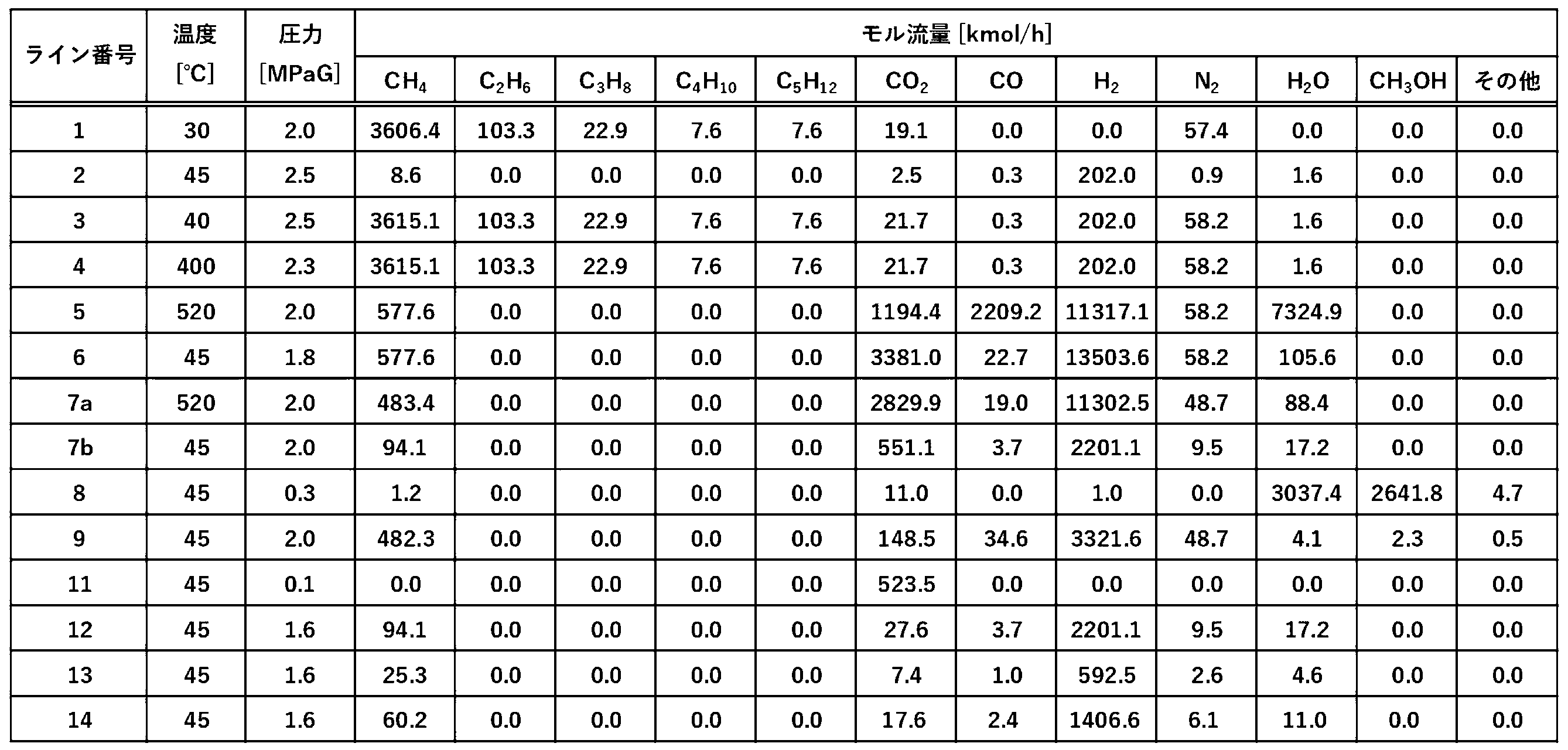
なお、表9中の比較例5におけるメタノール生産量(ton/day)は、表8中のライン8におけるメタノールのモル流量(kmol/h)に対して、メタノールのモル質量(g/mol)と24(h)とを乗じることで算出される。
また、表9中の比較例5における二酸化炭素排出量(ton/day)は、表8中のライン9、13、及び14における炭素原子のモル流量(kmol/h)の合計に対して、二酸化炭素のモル質量(g/mol)と24(h)とを乗じることで算出される。

<メタノール合成圧力>
メタノール合成反応器の入口のガス圧力を意味する。
<循環比>
循環比とは、メタノール合成ユニットにおいて、メタノール合成ユニットに供給される改質ガスのモル流量に対する、循環ガスのモル流量の比である。ここで、循環ガスとは、メタノール合成ユニット内でメタノール合成反応器の出口ガスからメタノール及び水を分離して得られるガスであって、同ユニットに外部から供給される改質ガスと同ユニット内で混合されてメタノール合成反応器に供給されるガスをいう。
<シェル圧>
多管式熱交換型反応器における、シェル側の内側、かつ、チューブの外側の圧力を意味する。
<メタノール合成ユニット入口のM値>
メタノール合成ユニット入口におけるM値を意味する。
<メタノール合成ユニット入口のH2/CO>
メタノール合成ユニット入口における、一酸化炭素のモル数と水素のモル数との比を意味する。
<触媒量>
実施例1の製造装置に用いた触媒量を100%とした場合における、各実施例又は比較例中の触媒量の質量比を意味する。
<炭素収率>
メタノール合成ユニットに供給される改質ガス中に含まれる一酸化炭素のモル流量と二酸化炭素のモル流量との合計量に対する、メタノール合成ユニットの出口ガスに含まれるメタノールのモル流量の比率を意味する。
Claims (17)
- 炭化水素含有ガスを改質して改質ガスを得る工程(A)と、
前記炭化水素含有ガス及び/又は前記改質ガスに対して水素含有ガスを混合する工程(B)と、
前記改質ガスの一部を触媒存在下で反応させてメタノール及び未反応ガスを得る工程(C)と、
前記改質ガスの残部をシフト反応させてシフト反応ガスを得る工程(D)と、
前記シフト反応ガスから二酸化炭素を分離して、二酸化炭素リッチガスと二酸化炭素分離ユニットオフガスを得る工程(E)と、を含み、
前記二酸化炭素分離ユニットオフガスの少なくとも一部が、前記工程(A)及び/又はボイラーの燃料として用いられる、
メタノール製造方法。 - 前記炭化水素含有ガスから硫黄分を除去する工程(F)をさらに含む、
請求項1に記載のメタノール製造方法。 - 前記メタノールから精製メタノールを得る工程(G)をさらに含む、
請求項1に記載のメタノール製造方法。 - 前記工程(C)に用いられる前記改質ガスのモル流量が、前記工程(A)で得られる改質ガスのモル流量に対して、50~95モル%である、
請求項1に記載のメタノール製造方法。 - 前記工程(C)で発生する水蒸気を、前記工程(G)及び/又は前記工程(E)で用いる、
請求項3に記載のメタノール製造方法。 - 前記工程(A)で回収された水蒸気を、前記工程(G)及び/又は前記工程(E)で用いる、
請求項3に記載のメタノール製造方法。 - 前記工程(A)で回収された熱を、前記工程(G)、及び前記工程(E)のうちの少なくともいずれかの熱源として用いる、
請求項3に記載のメタノール製造方法。 - 前記工程(D)は触媒存在下で行われる、
請求項1に記載のメタノール製造方法。 - 前記シフト反応ガス中の一酸化炭素濃度が、0.01~1.0モル%である、
請求項1に記載のメタノール製造方法。 - 前記シフト反応ガスが含有する二酸化炭素のモル流量を100モル%とした場合における、前記二酸化炭素リッチガスが含有する二酸化炭素のモル流量が、80~100モル%である、
請求項1に記載のメタノール製造方法。 - 前記未反応ガスの少なくとも一部をシフト反応ユニット及び/又は前記ボイラーへ供給する、
請求項1に記載のメタノール製造方法。 - 前記二酸化炭素分離ユニットオフガスからメタンを分離して、メタンリッチガス及びメタン分離ユニットオフガスを得る工程(H)をさらに含み、
前記メタン分離ユニットオフガスが、前記工程(A)及び/又は前記ボイラーの燃料に供給される、
請求項1に記載のメタノール製造方法。 - 前記二酸化炭素分離ユニットオフガス及び/又は前記メタン分離ユニットオフガスを、前記炭化水素含有ガス及び/又は前記改質ガスと混合させる、
請求項12に記載のメタノール製造方法。 - 前記二酸化炭素分離ユニットオフガスが含有するメタンのモル流量を100モル%とした場合における、前記メタンリッチガスが含有するメタンのモル流量が、50~99モル%である、
請求項12に記載のメタノール製造方法。 - 改質ユニットと、
メタノール合成ユニットと、
シフト反応ユニットと、
二酸化炭素分離ユニットと、を備え、
前記二酸化炭素分離ユニットにより得られる二酸化炭素分離ユニットオフガスが、前記改質ユニット及び/又はボイラーの燃料として用いられる、
メタノール製造装置。 - 脱硫ユニットをさらに備える、
請求項15に記載のメタノール製造装置。 - 前記二酸化炭素分離ユニットオフガスからメタンを分離するメタン分離ユニットをさらに備える、
請求項15に記載のメタノール製造装置。
Priority Applications (3)
| Application Number | Priority Date | Filing Date | Title |
|---|---|---|---|
| JP2024567728A JPWO2024143182A1 (ja) | 2022-12-26 | 2023-12-22 | |
| EP23911962.1A EP4644356A4 (en) | 2022-12-26 | 2023-12-22 | Methanol production method and methanol production device |
| CN202380078730.0A CN120187688A (zh) | 2022-12-26 | 2023-12-22 | 甲醇制造方法和甲醇制造装置 |
Applications Claiming Priority (2)
| Application Number | Priority Date | Filing Date | Title |
|---|---|---|---|
| JP2022208964 | 2022-12-26 | ||
| JP2022-208964 | 2022-12-26 |
Publications (1)
| Publication Number | Publication Date |
|---|---|
| WO2024143182A1 true WO2024143182A1 (ja) | 2024-07-04 |
Family
ID=91717630
Family Applications (1)
| Application Number | Title | Priority Date | Filing Date |
|---|---|---|---|
| PCT/JP2023/046092 Ceased WO2024143182A1 (ja) | 2022-12-26 | 2023-12-22 | メタノール製造方法及びメタノール製造装置 |
Country Status (4)
| Country | Link |
|---|---|
| EP (1) | EP4644356A4 (ja) |
| JP (1) | JPWO2024143182A1 (ja) |
| CN (1) | CN120187688A (ja) |
| WO (1) | WO2024143182A1 (ja) |
Citations (18)
| Publication number | Priority date | Publication date | Assignee | Title |
|---|---|---|---|---|
| JPS5144715A (ja) | 1974-10-16 | 1976-04-16 | Hitachi Ltd | Kyukikanetsusochi |
| JPS5144715B2 (ja) | 1973-10-24 | 1976-11-30 | ||
| JPH01180841A (ja) * | 1988-01-12 | 1989-07-18 | Mitsubishi Gas Chem Co Inc | メタノール製造法 |
| JPH0635401A (ja) | 1992-07-16 | 1994-02-10 | Nec Home Electron Ltd | 地図表示装置 |
| JPH08299796A (ja) | 1995-05-11 | 1996-11-19 | Mitsubishi Gas Chem Co Inc | メタノール合成触媒の製造法 |
| JP2695663B2 (ja) | 1989-08-07 | 1998-01-14 | 三菱重工業株式会社 | メタノール合成用触媒の製造方法 |
| JPH10272361A (ja) | 1997-03-31 | 1998-10-13 | Agency Of Ind Science & Technol | メタノール合成及び改質触媒 |
| JP2000063115A (ja) * | 1998-08-14 | 2000-02-29 | Mitsubishi Gas Chem Co Inc | メタノール・アンモニア併産方法 |
| JP2001205089A (ja) | 2000-01-24 | 2001-07-31 | Natl Inst Of Advanced Industrial Science & Technology Meti | メタノール合成用触媒およびその製造方法 |
| JP2002363578A (ja) * | 2001-06-01 | 2002-12-18 | Babcock Hitachi Kk | 水素・一酸化炭素混合ガスの製造方法および製造装置ならびに燃料・電力併産プラント |
| JP2004315474A (ja) * | 2003-04-18 | 2004-11-11 | Mitsubishi Heavy Ind Ltd | 酢酸の製造方法、及び酢酸の製造装置 |
| JP2009179804A (ja) * | 2001-01-19 | 2009-08-13 | Mitsubishi Heavy Ind Ltd | バイオマスガス化システム |
| JP2010138051A (ja) * | 2008-12-15 | 2010-06-24 | Toyo Eng Corp | メタノール及びアンモニアの併産方法 |
| WO2011048976A1 (ja) | 2009-10-23 | 2011-04-28 | 三菱瓦斯化学株式会社 | メタノール合成触媒 |
| US20170197894A1 (en) | 2014-04-29 | 2017-07-13 | Haldor Topsøes A/S | Process for production of methanol |
| US10160704B2 (en) | 2017-03-13 | 2018-12-25 | L'Air Liquide, Société Anonyme pour l'Etude et l'Exploitation des Procédés Georges Claude | Method and apparatus for improving the efficiency of reforming process for producing syngas and methanol while reducing the CO2 in a gaseous stream |
| EP3674261A1 (de) | 2018-12-27 | 2020-07-01 | GasConTec GmbH | Verfahren zur synthese einer wasserstoffhaltigen verbindung |
| EP3844135A1 (en) | 2018-08-29 | 2021-07-07 | ENI S.p.A. | Method and system for synthesizing methanol |
-
2023
- 2023-12-22 EP EP23911962.1A patent/EP4644356A4/en active Pending
- 2023-12-22 JP JP2024567728A patent/JPWO2024143182A1/ja active Pending
- 2023-12-22 WO PCT/JP2023/046092 patent/WO2024143182A1/ja not_active Ceased
- 2023-12-22 CN CN202380078730.0A patent/CN120187688A/zh active Pending
Patent Citations (18)
| Publication number | Priority date | Publication date | Assignee | Title |
|---|---|---|---|---|
| JPS5144715B2 (ja) | 1973-10-24 | 1976-11-30 | ||
| JPS5144715A (ja) | 1974-10-16 | 1976-04-16 | Hitachi Ltd | Kyukikanetsusochi |
| JPH01180841A (ja) * | 1988-01-12 | 1989-07-18 | Mitsubishi Gas Chem Co Inc | メタノール製造法 |
| JP2695663B2 (ja) | 1989-08-07 | 1998-01-14 | 三菱重工業株式会社 | メタノール合成用触媒の製造方法 |
| JPH0635401A (ja) | 1992-07-16 | 1994-02-10 | Nec Home Electron Ltd | 地図表示装置 |
| JPH08299796A (ja) | 1995-05-11 | 1996-11-19 | Mitsubishi Gas Chem Co Inc | メタノール合成触媒の製造法 |
| JPH10272361A (ja) | 1997-03-31 | 1998-10-13 | Agency Of Ind Science & Technol | メタノール合成及び改質触媒 |
| JP2000063115A (ja) * | 1998-08-14 | 2000-02-29 | Mitsubishi Gas Chem Co Inc | メタノール・アンモニア併産方法 |
| JP2001205089A (ja) | 2000-01-24 | 2001-07-31 | Natl Inst Of Advanced Industrial Science & Technology Meti | メタノール合成用触媒およびその製造方法 |
| JP2009179804A (ja) * | 2001-01-19 | 2009-08-13 | Mitsubishi Heavy Ind Ltd | バイオマスガス化システム |
| JP2002363578A (ja) * | 2001-06-01 | 2002-12-18 | Babcock Hitachi Kk | 水素・一酸化炭素混合ガスの製造方法および製造装置ならびに燃料・電力併産プラント |
| JP2004315474A (ja) * | 2003-04-18 | 2004-11-11 | Mitsubishi Heavy Ind Ltd | 酢酸の製造方法、及び酢酸の製造装置 |
| JP2010138051A (ja) * | 2008-12-15 | 2010-06-24 | Toyo Eng Corp | メタノール及びアンモニアの併産方法 |
| WO2011048976A1 (ja) | 2009-10-23 | 2011-04-28 | 三菱瓦斯化学株式会社 | メタノール合成触媒 |
| US20170197894A1 (en) | 2014-04-29 | 2017-07-13 | Haldor Topsøes A/S | Process for production of methanol |
| US10160704B2 (en) | 2017-03-13 | 2018-12-25 | L'Air Liquide, Société Anonyme pour l'Etude et l'Exploitation des Procédés Georges Claude | Method and apparatus for improving the efficiency of reforming process for producing syngas and methanol while reducing the CO2 in a gaseous stream |
| EP3844135A1 (en) | 2018-08-29 | 2021-07-07 | ENI S.p.A. | Method and system for synthesizing methanol |
| EP3674261A1 (de) | 2018-12-27 | 2020-07-01 | GasConTec GmbH | Verfahren zur synthese einer wasserstoffhaltigen verbindung |
Non-Patent Citations (1)
| Title |
|---|
| See also references of EP4644356A1 |
Also Published As
| Publication number | Publication date |
|---|---|
| CN120187688A (zh) | 2025-06-20 |
| JPWO2024143182A1 (ja) | 2024-07-04 |
| EP4644356A1 (en) | 2025-11-05 |
| EP4644356A4 (en) | 2026-05-06 |
Similar Documents
| Publication | Publication Date | Title |
|---|---|---|
| JP5355062B2 (ja) | メタノール及びアンモニアの併産方法 | |
| RU2408567C2 (ru) | Синтез метанола | |
| EP1277721A2 (en) | Method of manufacturing methanol | |
| US20130345326A1 (en) | Process for producing a synthesis gas mixture | |
| GB2585477A (en) | Process for synthesising methanol | |
| EP4522584B1 (en) | Process for synthesising methanol | |
| WO2016073046A1 (en) | Methods and systems for producing and processing syngas in a pressure swing adsorption unit and making ammonia therefrom | |
| US20240140891A1 (en) | Process for synthesising methanol | |
| AU2020290690B2 (en) | Process for synthesising methanol | |
| EA036440B1 (ru) | Способ получения стабилизированной формальдегидом мочевины | |
| GB2606855A (en) | Process for synthesising methanol | |
| EP4720025A1 (en) | Process for synthesising methanol | |
| WO2024143182A1 (ja) | メタノール製造方法及びメタノール製造装置 | |
| GB2634156A (en) | Process for synthesising methanol | |
| WO2025142740A1 (ja) | メタノール製造方法及びメタノール製造装置 | |
| RU2782258C2 (ru) | Способ получения метанола и аммиака | |
| WO2025257528A1 (en) | Low-carbon hydrogen process | |
| EA044078B1 (ru) | Очистка водорода |
Legal Events
| Date | Code | Title | Description |
|---|---|---|---|
| 121 | Ep: the epo has been informed by wipo that ep was designated in this application |
Ref document number: 23911962 Country of ref document: EP Kind code of ref document: A1 |
|
| WWE | Wipo information: entry into national phase |
Ref document number: 819707 Country of ref document: NZ |
|
| WWP | Wipo information: published in national office |
Ref document number: 819707 Country of ref document: NZ |
|
| WWE | Wipo information: entry into national phase |
Ref document number: 202380078730.0 Country of ref document: CN |
|
| WWE | Wipo information: entry into national phase |
Ref document number: 2024567728 Country of ref document: JP |
|
| WWP | Wipo information: published in national office |
Ref document number: 202380078730.0 Country of ref document: CN |
|
| WWE | Wipo information: entry into national phase |
Ref document number: P2025-01966 Country of ref document: AE |
|
| WWE | Wipo information: entry into national phase |
Ref document number: 2023911962 Country of ref document: EP |
|
| NENP | Non-entry into the national phase |
Ref country code: DE |
|
| ENP | Entry into the national phase |
Ref document number: 2023911962 Country of ref document: EP Effective date: 20250728 |
|
| ENP | Entry into the national phase |
Ref document number: 2023911962 Country of ref document: EP Effective date: 20250728 |
|
| WWP | Wipo information: published in national office |
Ref document number: 2023911962 Country of ref document: EP |