WO2024150285A1 - Système de transport, procédé de transport et véhicule de transport destiné à être utilisé dans un système de transport - Google Patents
Système de transport, procédé de transport et véhicule de transport destiné à être utilisé dans un système de transport Download PDFInfo
- Publication number
- WO2024150285A1 WO2024150285A1 PCT/JP2023/000348 JP2023000348W WO2024150285A1 WO 2024150285 A1 WO2024150285 A1 WO 2024150285A1 JP 2023000348 W JP2023000348 W JP 2023000348W WO 2024150285 A1 WO2024150285 A1 WO 2024150285A1
- Authority
- WO
- WIPO (PCT)
- Prior art keywords
- trailer
- transport
- transport vehicle
- parked
- unit
- Prior art date
- Legal status (The legal status is an assumption and is not a legal conclusion. Google has not performed a legal analysis and makes no representation as to the accuracy of the status listed.)
- Ceased
Links
Images






Classifications
-
- G—PHYSICS
- G08—SIGNALLING
- G08G—TRAFFIC CONTROL SYSTEMS
- G08G1/00—Traffic control systems for road vehicles
- G08G1/14—Traffic control systems for road vehicles indicating individual free spaces in parking areas
Definitions
- This disclosure relates to a transport system, a transport method, and a transport vehicle used in the transport system.
- a distribution center is a facility that serves as a base for the transportation and distribution of goods.
- a truck towing a trailer loaded with goods enters a distribution center, and the trailer loaded with goods is parked on the distribution center's premises.
- the goods loaded onto the trailer are brought into a warehouse set up in the distribution center, and the trailer unloaded with the goods is parked as an empty trailer on the distribution center's premises.
- goods that have been removed from the warehouse are loaded onto the empty trailer.
- the trailer loaded with the goods is then towed by a truck and taken out of the distribution center, thereby transporting the goods.
- transportation of goods is carried out using the distribution center as a base.
- trailer transportation has been performed manually using transportation equipment such as a human-driven vehicle or a trailer dolly.
- transportation vehicles such as autonomous vehicles that can travel autonomously.
- a transport vehicle is engaged with a trailer parked in a parking position at a distribution center to transport the trailer to a warehouse or park the trailer in a parking lot, and that the position of the trailer to be transported is identified based on the trailer's position information, and that the position of the trailer parked in the parking lot is identified (see, for example, Patent Document 1).
- Patent Document 1 does not specifically disclose a method for selecting a trailer to be transported or a method for identifying the parking position of the trailer to be transported.
- the traffic path of the transport vehicle or trailer will be long, hindering the movement of other transport vehicles or external vehicles such as trucks, resulting in reduced operational efficiency.
- This disclosure has been made to solve the problems described above, and aims to provide a transport system, a transport method, and a transport vehicle used in the transport system that do not impede the movement of transport vehicles or external vehicles and improve operational efficiency.
- the transport system disclosed herein is a transport system for connecting a transport vehicle to a trailer parked within the premises of a distribution center and moving the trailer to a warehouse provided at the distribution center or a parking lot of the distribution center by the transport vehicle, and includes a driving plan generation unit that generates a driving plan for the transport vehicle used to transport the trailer from the parking lot to the warehouse or from the warehouse to the parking lot by the transport vehicle, a recognition unit that detects the position of the trailer within the premises, and a parking position determination unit that determines a section in which the trailer will be parked by the transport vehicle from the detection result by the recognition unit, and the driving plan generation unit generates a driving plan by setting the section in which the trailer will be parked, determined by the parking position determination unit, as the parking position of the trailer.
- the transportation method disclosed herein is a transportation method for coupling a transportation vehicle to a trailer parked within the premises of a distribution center and moving the trailer by the transportation vehicle to a warehouse provided at the distribution center or a parking lot of the distribution center, in which a driving plan generation unit generates a driving plan for the transportation vehicle used to transport the trailer from the parking lot to the warehouse or from the warehouse to the parking lot by the transportation vehicle, a recognition unit detects the position of the trailer within the premises, a parking position determination unit determines a section in which the trailer will be parked by the transportation vehicle from the detection result by the recognition unit, and the driving plan generation unit generates a driving plan by setting the section in which the trailer will be parked determined by the parking position determination unit as the parking position of the trailer.
- the transport vehicle according to the present disclosure is a transport vehicle used in a transport system, and is equipped with a driving control unit that executes driving control based on a driving plan generated by a driving plan generation unit possessed by the transport system.
- transport vehicles do not impede the movement of other transport vehicles or external vehicles, improving the operational efficiency of the transport system.
- FIG. 2 is an explanatory diagram showing a delivery center according to the first embodiment.
- FIG. 2 is an explanatory diagram showing an example of the arrangement of roadside sensors according to the first embodiment;
- 1 is an explanatory diagram showing the connection relationship between a control device, a transport vehicle, and a roadside sensor according to a first embodiment;
- FIG. 2 is a configuration diagram showing the configuration of a control device according to the first embodiment.
- 1 is a configuration diagram showing a configuration of a driving control device provided in a transport vehicle according to a first embodiment;
- 5A to 5C are explanatory diagrams showing a coupling operation between the transport vehicle and the trailer according to the first embodiment.
- 5 is a flowchart showing an example of the operation of the control device and the transport vehicle when transporting the trailer according to the first embodiment.
- 5 is an explanatory diagram showing an example of the operation of the transport vehicle according to the first embodiment;
- FIG. 5 is an explanatory diagram showing an example of the operation of the transport vehicle according to the first embodiment;
- FIG. 5 is an explanatory diagram showing an example of the operation of the transport vehicle according to the first embodiment;
- FIG. 5 is an explanatory diagram showing an example of the operation of the transport vehicle according to the first embodiment;
- FIG. 5 is an explanatory diagram showing an example of the operation of the transport vehicle according to the first embodiment;
- FIG. 5 is an explanatory diagram showing an operation example of the transport vehicle according to the first embodiment;
- FIG. 5 is an explanatory diagram showing an operation example of the transport vehicle according to the first embodiment;
- FIG. 5 is an explanatory diagram showing an operation example of the transport vehicle according to the first embodiment;
- FIG. 5 is an explanatory diagram showing an operation
- FIG. 5 is an explanatory diagram showing an example of the operation of the transport vehicle according to the first embodiment
- FIG. 5 is an explanatory diagram showing an example of the operation of the transport vehicle according to the first embodiment
- FIG. 5 is an explanatory diagram showing an example of the operation of the transport vehicle according to the first embodiment
- FIG. 5 is an explanatory diagram showing an example of the operation of the transport vehicle according to the first embodiment
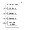
- FIG. 2 is a configuration diagram showing a part of the configuration of a control device according to the first embodiment.
- FIG. 5 is a flowchart showing an operation example of the transport system according to the first embodiment.
- FIG. 2 is a diagram illustrating an example of a hardware configuration of the transport system according to the first embodiment.
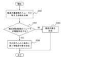
- FIG. 11 is a configuration diagram showing a part of the configuration of a control device according to a second embodiment. 13 is a flowchart showing an operation example of the transport system according to the second embodiment.
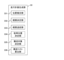
- FIG. 11 is a configuration diagram showing a part of the configuration of a control device according to a third embodiment.
- the transport system 100 in this disclosure will be described using an example in which a truck 6 towing a trailer 5 enters a distribution center 1, and the trailer 5 is towed by the truck 6 to exit the distribution center 1, but the transport system 100 in this disclosure is applicable to at least moving the trailer 5 by a transport vehicle 4.
- a transport vehicle 4 a transport vehicle 4
- no distinction is made between trucks and tractors, and an external vehicle towing a trailer 5 is referred to as a truck.
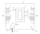
- Fig. 1 is an explanatory diagram showing a distribution center 1 according to the first embodiment.
- Fig. 1 is a schematic diagram showing an overhead view of the distribution center 1.
- the distribution center 1 has a warehouse 11 in which goods are stored, an entrance 12 and an exit 13 provided for a truck 6 pulling a trailer 5 loaded with goods to enter and leave the premises of the distribution center 1, and a parking lot 14 provided within the premises as an area in which the trailer 5 is parked.
- the distribution center 1 is also provided with a sensor (hereinafter referred to as a roadside sensor 2) that is fixed to a structure present in the distribution center 1 and detects at least an object within the premises.
- a sensor hereinafter referred to as a roadside sensor 2
- the distribution center 1 is surrounded by a fence 16, which separates the inside and outside of the premises.
- FIG. 1 shows an example in which the distribution center 1 has a rectangular premises, but the shape of the premises of the distribution center 1 is arbitrary.
- the warehouse 11 of the distribution center 1 is provided within the premises of the distribution center 1, and is located, for example, in the center of the premises. In the warehouse 11, goods unloaded from the trailers 5 or goods to be loaded onto the trailers 5 are stored.
- the warehouse 11 is provided with one or more platforms 17, and goods are transported into the warehouse 11 via the platforms 17. In addition, when goods stored in the warehouse 11 are to be delivered, they are transported out via the platform 17 of the warehouse 11 and loaded onto the trailers 5.
- the platform 17 from which goods are transported there is no distinction between the platform 17 from which goods are transported and the platform 17 to which goods are transported, but for example, the platform 17 shown on the left side of FIG. 1 may be the platform to which goods are transported, and the platform 17 shown on the right side of FIG. 1 may be the platform from which goods are transported.
- the movement of the trailer 5 is carried out by one or more transport vehicles 4 traveling on the grounds of the distribution center 1, as will be described in detail later.
- the entrance 12 of the distribution center 1 is connected to a road outside the site, and trucks 6 can enter the site from outside through the entrance 12.
- An entrance gate 18 is also provided at the entrance 12 of the distribution center 1, and a monitor or the like positioned at the entrance gate 18 manages the trucks 6 that are allowed to enter, restricting the entry of unauthorized trucks 6.
- the driver of a truck 6 entering the distribution center 1 is instructed by the monitor or the like positioned at the entrance gate 18 which parking space 15 to park the trailer 5 in.
- the parking space 15 in which the truck 6 parks the trailer 5 may be determined by the control device 3, which will be described later.
- the exit 13 of the distribution center 1, like the entrance 12 of the distribution center 1, is connected to a road outside the site, and trucks 6 can exit from inside the site to outside the site via the exit 13.
- An exit gate 19 is also provided at the exit 13 of the distribution center 1, and the exiting trucks 6 are managed by a monitor or the like stationed at the exit gate 19. Note that, although the entrance 12 and the exit 13 are provided at different locations in the example of FIG. 1, the entrance 12 and the exit 13 may be provided at the same location.
- the distribution center 1 has one or more parking lots 14 on its premises, and each parking lot 14 has multiple parking spaces 15.
- Each parking space 15 is divided by markers such as white lines, and each parking space 15 has a width that is, for example, greater than or equal to the width of a trailer 5 so that the trailer 5 can be parked therein.
- parking lot 14A the parking lot 14 on the left side of FIG. 1
- parking lot 14B the parking lot 14 on the right side of FIG. 1
- the parking spaces 15 provided in parking lot 14A will be referred to as parking spaces 15A-15K from the bottom in FIG. 1
- parking spaces 15L-15V the parking spaces 15L-15V from the bottom in FIG. 1.
- parking lots 14A and 14B they will simply be referred to as parking lots 14, and when it is not necessary to distinguish between the parking spaces 15A-V, they will simply be referred to as parking spaces 15.
- Parking spaces 15 are used to park trailers 5 loaded with goods or empty trailers 5 not loaded with goods.
- parking spaces 15C, 15D, 15E, 15I, 15K, 15N, 15O, 15P, 15R, and 15V have trailers 5 parked
- parking spaces 15A, 15B, 15F, 15G, 15H, 15J, 15L, 15M, 15Q, 15S, 15T, and 15U are empty spaces where no trailers 5 are parked.
- one or more parking spaces 15 with an empty space equal to or larger than the width of a trailer 5 are referred to as a parking space. That is, in the example of FIG. 1, parking spaces 15A, 15B, 15F, 15G, 15H, 15J, 15L, 15M, 15Q, 15S, 15T, and 15U are parking spaces. Additionally, multiple adjacent parking spaces may be considered as one parking space.
- the roadside sensors 2 installed in the distribution center 1 are composed of at least one of, for example, a camera, a sonar, a LiDAR (Light Detection and Ranging), and a radio wave sensor, and detect moving objects including trucks 6, transport vehicles 4, and pedestrians, obstacles present on the grounds of the distribution center 1, and surrounding objects present on the grounds of the distribution center 1. Note that in the example of Figure 1, some of the roadside sensors 2 are not shown for simplicity.
- FIG. 2 is an explanatory diagram showing an example of the arrangement of roadside sensors 2 according to the first embodiment.
- the detection range of the roadside sensor 2 is indicated by a dashed line.
- Multiple roadside sensors 2 are installed on the grounds of the distribution center 1, and are fixed to the roof of the warehouse 11, the fence 16 of the distribution center 1, or structures such as posts installed in the distribution center 1.
- the roadside sensors 2 are installed so that the detection range formed by one or more roadside sensors 2 includes at least the parking lot 14 and the platform 17 of the warehouse 11. It is also preferable to install multiple roadside sensors 2 so that the detection range includes the entire grounds of the distribution center 1.
- the sensor information acquired by the roadside sensor 2 is transmitted to the control device 3 via a communication unit (not shown) possessed by the roadside sensor 2 and is used to generate a driving plan for the transport vehicle 4, which will be described later, or to control the driving and braking of the transport vehicle 4.
- a communication unit not shown
- trucks 6 and trailers 5 there are many objects with larger dimensions, such as trucks 6 and trailers 5, compared to ordinary roads such as public roads.
- trucks 6 and transport vehicles 4 there is no clear distinction between areas where the trucks 6 and transport vehicles 4 can travel and areas where people such as workers can move, and various moving objects come and go.
- the environment of the distribution center 1 is significantly different from that of a general road in that there are many blind spots in the distribution center 1 and various moving objects. Therefore, it is preferable to arrange multiple roadside sensors 2 in the distribution center 1 to prevent blind spots of the roadside sensors 2.
- the roadside sensor 2 fixed to the fence 16 of the distribution center 1 and arranged on the parking lot 14 side is arranged facing the warehouse 11 side so that at least a part of the platform 17 of the warehouse 11, such as one or more platforms 17 of the warehouse 11, is included in the detection range.
- the roadside sensor 2 fixed to the roof of the warehouse 11 and arranged on the warehouse 11 side is arranged facing the parking lot 14 side so that at least a part of the parking lot 14, such as one or more parking spaces 15, is included in the detection range.
- the roadside sensors 2 By arranging the roadside sensors 2 in this manner, objects in the parking lot 14, objects on the platform 17, and objects in the passage between the parking lot 14 and the platform 17 can each be detected by the multiple roadside sensors 2. Furthermore, because the roadside sensors 2 are arranged opposite each other, even if, for example, a truck 6 crosses the passage between the parking lot 14 and the warehouse 11, creating an area that is hidden by the truck 6 and is a blind spot for the roadside sensor 2 arranged on the parking lot 14 side, the blind spot is included in the detection range of the roadside sensor 2 arranged on the warehouse 11 side. Conversely, even if an area is hidden by the truck 6 and is a blind spot for the roadside sensor 2 arranged on the warehouse 11 side, the blind spot is included in the detection range of the roadside sensor 2 arranged on the parking lot 14 side.
- the roadside sensor 2 can detect the object. Therefore, in generating a driving plan for the transport vehicle 4 or controlling the driving and braking of the transport vehicle 4 (described later), it is possible to prevent a collision with an object that jumps out of the blind spot of the transport vehicle 4 while traveling.
- control device 3 can generate a driving plan that avoids the parking space 15 and platform 17 where the transport vehicle 4, trailer 5, truck 6, or worker is present, thereby improving the operational efficiency of the distribution center 1.
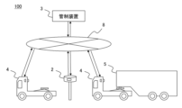
- FIG. 3 is an explanatory diagram showing the connection relationship between the control device 3, the transport vehicle 4, and the roadside sensor 2 according to the first embodiment.
- the roadside sensor 2 and the transport vehicle 4 traveling within the distribution center 1 communicate with the control device 3 via a network 8.
- the control device 3 receives, via the network 8, on-board sensor information transmitted from the transport vehicle 4 and roadside sensor information transmitted from the roadside sensor 2, and generates a driving plan for the transport vehicle 4 using the on-board sensor information and the roadside sensor information.
- the transport system 100 is a system that includes the control device 3 and the transport vehicle 4.
- the control device 3 also transmits a driving plan to the transport vehicle 4 via the network 8.
- the transport vehicle 4 then performs autonomous driving and transport of the trailer 5 based on the received driving plan.
- the on-board sensor information transmitted from the transport vehicle 4 and the roadside sensor information transmitted from the roadside sensor 2 may be collectively referred to as sensor information.
- the transport vehicle 4 or the roadside sensor 2 may be connected to an edge server (not shown) that processes the sensor information, and the edge server may be connected to the control device 3 via the network 8.
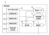
- FIG. 4 is a configuration diagram showing the configuration of the control device 3 according to the first embodiment.
- the control device 3 includes a map information storage unit 31 in which map information of the distribution center 1 is stored, a vehicle database 32 which is a database capable of storing information on the transport vehicle 4 and the trailer 5 present in the distribution center 1, a driving plan generation unit 33 which generates a driving plan used for the autonomous driving of the transport vehicle 4, a communication unit 34 which communicates with the roadside sensor 2 and the transport vehicle 4, and a recognition unit 35 which generates surrounding recognition information for recognizing the environment within the premises of the distribution center 1.
- the parking position determination unit 334 shown in FIG. 4 will be described in detail later.
- At least one of the map information storage unit 31, the vehicle database 32, the driving plan generation unit 33, the communication unit 34, and the recognition unit 35 of the control device 3 may be provided in an edge server. That is, for example, the recognition unit 35 may be provided in the edge server, and the surrounding recognition information may be transmitted from the edge server to the control device 3.
- the map information stored in the map information storage unit 31 is a high-precision base map used for autonomous driving.
- the map information includes, for example, the passages present on the premises of the distribution center 1, the connections of the passages, the width and length of the passages, the road surface of the passages, and the position information of surrounding features such as the warehouse 11 of the distribution center 1.
- the map information may be composed of a high-precision three-dimensional map that reflects the position information of surrounding features and obstacles.
- the high-precision three-dimensional map may be composed of a point cloud, line segments, and a three-dimensional model of features, etc., expressed using high-precision three-dimensional position coordinates of centimeter to sub-meter order according to a reference coordinate system such as the World Geographic System (WGS) or a geodetic system.
- GSS World Geographic System
- the vehicle database 32 is a database that stores information on multiple transport vehicles 4 managed by the control device 3.
- the vehicle database 32 stores, for example, the ID of the transport vehicle 4 and the status of the transport vehicle 4, such as whether or not it is transporting a trailer 5.
- the vehicle database 32 also stores information on the trailers 5 present within the distribution center 1, such as the parking position of the trailer 5, the type of trailer 5, the dimensions of the trailer 5, whether or not the trailer 5 is loaded with goods, the date and time of entry, and the date and time of exit.
- the recognition unit 35 generates surrounding recognition information for recognizing the environment within the premises of the distribution center 1 based on the sensor information of the on-board sensor and the roadside sensor 2 acquired via the communication unit 34.
- the environment within the premises of the distribution center 1 refers to the presence or absence of objects within the premises of the distribution center 1, etc.
- the surrounding recognition information generated by the recognition unit 35 includes position information indicating the parking position and available parking areas of the trailers 5 present in the distribution center 1.
- the sensor information transmitted from the on-board sensor also includes information sensed by an external sensor 415 provided in the transport vehicle 4 and sensing the environment around the transport vehicle 4.
- the sensor information transmitted from the on-board sensor may also include location information acquired by a GPS receiver 414 provided in the transport vehicle 4.
- the sensor information transmitted from the on-board sensor may also include information such as the vehicle attitude and on-board weight of the transport vehicle 4.
- the on-board sensor may include not only the external sensor 415, but also other sensors mounted on the transport vehicle 4.
- the driving plan generation unit 33 generates a driving plan for the transport vehicle 4 based on map information and sensor information transmitted from the transport vehicle 4 and the roadside sensor 2 so that the transport vehicle 4 travels autonomously along the travel route.
- the driving plan generation unit 33 has a position estimation unit 331.
- the position estimation unit 331 estimates transport vehicle position information including the position of the transport vehicle 4 and the direction in which the transport vehicle 4 is facing based on map information and sensor information. Specifically, the position estimation unit 331 estimates transport vehicle position information based on surrounding recognition information and map information.
- the driving plan generating unit 33 has a route determining unit 332.
- the route determining unit 332 generates a driving route for the transport vehicle 4 based on map information, transport vehicle position information, and surrounding recognition information.
- the driving plan generating unit 33 when the driving plan generating unit 33 generates a driving plan for driving the transport vehicle 4 toward the trailer 5 or the parking space 15 for transporting the trailer 5, the driving plan generating unit 33 generates a driving route for the transport vehicle 4 based on map information, transport vehicle position information, surrounding recognition information, and the position information of the trailer 5 to be transported or the parking space 15 where the trailer 5 is parked.
- the travel route when the transport vehicle 4 transports the trailer 5, the travel route includes the position where the trailer 5 to be transported is parked (hereinafter referred to as the first parking position) and the position where the trailer 5 to be transported is to be parked (hereinafter referred to as the second parking position).
- the first parking position is, for example, the parking space 15 or the platform 17 of the warehouse 11
- the second parking position is, for example, the parking space or the platform 17 of the warehouse 11.
- the travel route is represented by, for example, dividing the route from the current position of the transport vehicle 4 to the target position into multiple routes.
- the travel route includes, for example, multiple points on the way to the target position, and these multiple points are the points through which the transport vehicle 4 must pass.
- the driving plan generating unit 33 has a route following unit 333.
- the route following unit 333 generates control information including speed control information for controlling the speed of the transport vehicle 4 and direction control information for controlling the steering angle of the transport vehicle 4 based on the driving route and the transport vehicle position information. Then, the driving plan generating unit 33 transmits the driving plan to the transport vehicle 4 via the communication unit 34.
- the driving plan generated by the driving plan generating unit 33 includes the driving route of the transport vehicle 4 and control information for the transport vehicle 4 to travel along the driving route.
- the speed indicates the speed of the transport vehicle 4
- the steering angle indicates the traveling direction of the transport vehicle 4.
- the speed and steering angle can be rephrased as speed and steering angle, or speed and traveling direction.
- the driving plan transmitted from the driving plan generating unit 33 may not include control information.
- the driving control unit 411 of the driving control device 41 described later may generate control information so as to follow the driving route generated by the driving plan generating unit 33.
- the route following unit 333 of the management device 3 can be omitted as appropriate.
- the driving plan generation unit 33 generates a driving plan for each transport vehicle 4.
- the driving plan generation unit 33 When generating driving plans for multiple transport vehicles 4, the driving plan generation unit 33 generates driving routes for the multiple transport vehicles 4 so that the driving routes of one transport vehicle 4 do not intersect with the driving routes of the other transport vehicles 4, for example, to generate a driving plan so that the multiple transport vehicles 4 do not interfere with each other's driving routes. This improves the operational efficiency of the distribution center 1 because the multiple transport vehicles 4 do not interfere with each other's driving.
- FIG. 5 is a configuration diagram showing the configuration of the driving control device 41 provided in the transport vehicle 4 according to the first embodiment.
- the driving control device 41 includes a driving control unit 411 that controls the steering mechanism 43 and braking/driving mechanism 44 of the transport vehicle 4 to control the driving of the transport vehicle 4 based on the driving plan received from the control device 3.
- the driving control device 41 also includes a map information storage unit 412 that stores map information used for the autonomous driving of the transport vehicle 4, a surrounding situation monitoring unit 413 that monitors the surrounding situation of the transport vehicle 4, a vehicle status acquisition unit 417 that acquires information indicating the status of the transport vehicle 4 on which the driving control device 41 is mounted, an on-board communication unit 423 that is configured to be capable of wireless communication, and a coupling control unit 424 that controls the coupling and uncoupling of the trailer 5 and the transport vehicle 4.
- a map information storage unit 412 that stores map information used for the autonomous driving of the transport vehicle 4
- a surrounding situation monitoring unit 413 that monitors the surrounding situation of the transport vehicle 4
- a vehicle status acquisition unit 417 that acquires information indicating the status of the transport vehicle 4 on which the driving control device 41 is mounted
- an on-board communication unit 423 that is configured to be capable of wireless communication
- a coupling control unit 424 that controls the coupling and uncoupling of the trailer 5 and the transport vehicle 4.
- the driving control unit 411, the map information storage unit 412, the surrounding conditions monitoring unit 413, and the vehicle state acquisition unit 417 of the driving control device 41 are each connected to the communication bus 422 of the driving control device 41, and data can be sent and received via the communication bus 422.
- the steering mechanism 43 is a mechanism provided in the transport vehicle 4 for determining the direction of travel of the transport vehicle 4, and includes, for example, a steering wheel, a steering shaft, a rack, a pinion, and a steering actuator 431.
- the braking/driving mechanism 44 is a mechanism for controlling the travel speed of the transport vehicle 4 and for switching between forward and reverse, and includes, for example, a driving device such as an engine and a motor, an accelerator, a brake, a shift, and a braking/driving actuator 441.
- the steering actuator 431 that controls the steering mechanism 43 is, for example, composed of an EPS (Electric Power Steering) motor, and the braking/driving actuator 441 that controls the braking/driving mechanism 44 is, for example, composed of an electronically controlled throttle, a brake actuator, and the like.
- EPS Electrical Power Steering
- the braking/driving actuator 441 that controls the braking/driving mechanism 44 is, for example, composed of an electronically controlled throttle, a brake actuator, and the like.
- the transport vehicle 4 only performs autonomous driving, mechanisms that are assumed to be operated by a person, such as a steering wheel, an accelerator, and a brake, are not essential and can be omitted as appropriate.
- the map information storage unit 412 stores map information.
- the map information stored in the map information storage unit 31 is a high-precision base map used for autonomous driving, similar to the map information stored in the map information storage unit 31 of the control device 3.
- the map information includes, for example, the passages present on the premises of the distribution center 1, the connections of the passages, the width and length of the passages, the road surface of the passages, and the position information of surrounding features such as the warehouse 11 of the distribution center 1.
- the map information may be composed of a high-precision three-dimensional map that can show the passages that the transport vehicle 4 and the like can pass through, the road surface of the passages, and surrounding features.
- the map information stored in the map information storage unit 412 may be updated by map information that reflects the position information of the trailer 5, distributed from the control device 3.
- the transport vehicle 4 can travel autonomously even if the driving control device 41 does not have a map information storage unit 412, and if the driving control device 41 is equipped with a map information storage unit 412, the transport vehicle 4 can travel autonomously even if the control device 3 does not have a map information storage unit 31. In other words, it is sufficient that map information is stored in at least one of the map information storage unit 31 provided in the control device 3 or the map information storage unit 412 provided in the driving control device 41.
- the surrounding situation monitoring unit 413 is configured to be able to monitor the situation around the vehicle, and includes a GPS (Global Positioning System) receiver 414, an external sensor 415, and a surrounding recognition unit 416.
- GPS Global Positioning System
- the GPS receiver 414 receives signals transmitted from GPS positioning satellites and detects the current position of the transport vehicle 4 as transport vehicle position information.
- a GNSS Global Navigation Satellite System
- a GNSS receiver may be provided in the driving control device 41, or a GNSS receiver may be provided in place of the GPS receiver 414.
- the external sensor 415 is composed of, for example, at least one of a camera that captures images outside the vehicle, a sonar, a LiDAR, and a radio wave sensor, and detects the positions of other vehicles, pedestrians, obstacles, etc. that are present in the vicinity of the transport vehicle 4, or the distance from the vehicle itself, etc.
- the surroundings recognition unit 416 recognizes the environment around the vehicle based on the transport vehicle position information and sensor information of the transport vehicle 4 acquired from the GPS receiver 414 and the external sensor 415.
- the environment around the vehicle refers to the presence or absence of objects around the vehicle, such as the detection range of the external sensor 415.
- the on-board communication unit 423 is, for example, a wireless communication device connected to an antenna for wireless communication.
- the on-board communication unit 423 acquires information on the positions of other vehicles and pedestrians by communicating with on-board communication units provided in other transport vehicles 4 or communication units installed on the road.
- the in-vehicle communication unit 423 can also communicate between vehicles via wireless communication, i.e., vehicle-to-vehicle communication, with the in-vehicle communication units 423 of other vehicles around the vehicle.
- the in-vehicle communication unit 423 can output information received from other vehicles to the communication bus 422.
- the in-vehicle communication unit 423 can also be configured to acquire information from the roadside sensor 2.
- the in-vehicle communication unit 423 is configured to be able to transmit information generated in the driving control device 41 and output to the communication bus 422 to the control device 3 and other vehicles.
- the sensor information transmitted from the transport vehicle 4 to the control device 3 may include transport vehicle position information, speed, steering angle, etc. in addition to the sensor information acquired by the external sensor 415.
- the vehicle state acquisition unit 417 acquires information indicating the state of the vehicle itself, and includes a steering angle sensor 418, a vehicle speed sensor 419, a gyro sensor 420, and an acceleration sensor 421.
- the steering angle sensor 418 is provided, for example, on the EPS motor or steering wheel, and detects the steering angle of the vehicle.
- the vehicle speed sensor 419 is provided, for example, on the wheels, and detects the traveling speed of the vehicle.
- the gyro sensor 420 is a sensor that detects the angular velocity in the azimuth direction when the transport vehicle 4 turns.
- the acceleration sensor 421 is a sensor that detects the acceleration in the front-to-rear direction (e.g., vehicle length direction), left-to-right direction (e.g., vehicle width direction), and up-down direction (e.g., vehicle height direction) of the transport vehicle 4. Note that even if position information of the transport vehicle 4 cannot be obtained from the GPS receiver 414 or the like, the position of the transport vehicle 4 can be estimated by using the angular velocity and acceleration in each direction obtained by the gyro sensor 420 and the acceleration sensor 421.
- the driving control unit 411 of the driving control device 41 controls the steering actuator 431 or braking/driving actuator 441 mounted on the vehicle to perform autonomous driving.
- the driving control unit 411 controls the driving of the vehicle by, for example, outputting a signal to the steering actuator 431 or braking/driving actuator 441.
- the driving control unit 411 performs braking/driving control of the host vehicle, such as by controlling a braking/driving actuator 441 consisting of an electronically controlled throttle and a brake actuator, etc. to operate the brakes and slow down or stop the host vehicle.
- the driving control unit 411 performs steering control of the host vehicle, such as by controlling a steering actuator 431 consisting of an EPS motor, etc. to maintain the driving route on which the host vehicle is traveling.
- the driving control unit 411 generates control information and controls the steering actuator 431 and the braking/driving actuator 441 so as to follow the driving route included in the driving plan received from the control device 3, thereby realizing autonomous driving of the transport vehicle 4 based on the driving plan.
- the driving control unit 411 may also realize autonomous driving of the transport vehicle 4 based on the driving plan by controlling the steering actuator 431 and the braking/driving actuator 441 using the control information included in the driving plan so as to follow the driving route included in the driving plan received from the control device 3.
- a display device (not shown) may be provided in the transport vehicle 4, and the display device may be made to display the driving route included in the driving plan received from the control device 3, thereby enabling the transport vehicle 4 to drive based on the driving plan.
- the driving control unit 411 executes emergency stop control to automatically stop the transport vehicle 4.
- the driving control unit 411 stops the transport vehicle 4 on the spot.
- the driving control unit 411 may cause the surrounding situation monitoring unit 413 to search for an evacuation location to stop the transport vehicle, and move the transport vehicle 4 to the evacuation location and stop it.
- the above-mentioned evacuation location is preferably a location that does not impede the movement of other moving bodies, such as outside the travel route of other transport vehicles 4.
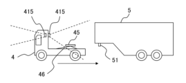
- the coupling control unit 424 raises and lowers the fifth wheel 45 provided on the base or the like of the transport vehicle 4, and couples or uncouples the transport vehicle 4 and the trailer 5.
- the coupling control unit 424 sends a signal to a lift 46 provided on the transport vehicle 4, and drives the lift 46 to raise and lower the fifth wheel 45.
- the fifth wheel 45 is provided on the base. That is, in the example of FIG. 6, the transport vehicle 4 retreats and approaches the trailer 5. Then, the connection control unit 424 of the transport vehicle 4 drives the lift 46 to raise the fifth wheel 45 and engage the fifth wheel 45 with the kingpin 51, completing the connection between the transport vehicle 4 and the trailer 5.
- the transport vehicle 4 needs to approach the trailer 5.
- the area between the transport vehicle 4 and the trailer 5 may be in a blind spot of the external sensor 415 mounted on the other transport vehicle 4, or in a blind spot of the roadside sensor 2. Therefore, it is preferable that the driving control unit 411 executes driving control of the transport vehicle 4 connected to the trailer 5 using sensor information acquired by the external sensor 415 installed on the transport vehicle 4 connected to the trailer 5.
- the transport vehicle 4 moves the trailer 5 to the parking position, and then the coupling control unit 424 drives the lift 46 to lower the fifth wheel 45, completing the uncoupling of the transport vehicle 4 and the trailer 5.
- a robot having a manipulator may be mounted on the base of the transport vehicle 4, and the robot may automatically connect the air pressure line or the cable.
- the above-mentioned robot may automatically remove the cable.
- the on-board communication unit 423 may transmit a signal indicating that the coupling or uncoupling of the transport vehicle 4 and the trailer 5 has been completed or started to a control device (not shown) that controls the robot, and the robot may connect or remove the cable.
- Figure 7 is a flowchart showing an example of the operation of the control device 3 and the operation control device 41 during transportation of the trailer 5 according to the first embodiment.
- the external sensor 415 or the roadside sensor 2 of the transport vehicle 4 acquires sensor information.
- the external sensor 415 or the roadside sensor 2 which is composed of a camera, a sonar, a radio wave sensor, a LiDAR, etc., senses the inside of the distribution center 1 premises.
- step S102 the communication unit of the roadside sensor 2 or the on-board communication unit 423 of the transport vehicle 4 transmits the sensor information obtained by sensing to the control device 3.
- step S103 the communication unit 34 of the control device 3 receives sensor information from the roadside sensor 2 and the transport vehicle 4. Note that steps S101, S102, and S103 may be executed repeatedly.
- step S104 the driving plan generating unit 33 of the control device 3 determines the trailer 5 to be transported. That is, the driving plan generating unit 33 identifies the first parking position where the trailer 5 to be transported is parked, and the second parking position where the trailer 5 to be transported is to be parked.
- the trailer 5 to be transported may be determined based on the recognition result of the recognition unit 35, or may be determined by the manager of the distribution center 1 who operates the control device 3 via a user interface.
- the driving plan generation unit 33 determines the trailer 5 parked in the parking lot 14 as the trailer to be transported when the recognition unit 35 detects, for example, a trailer 5 parked in the parking lot 14 and a platform 17 on which no other trailers 5 are present.
- the driving plan generation unit 33 determines the trailer 5 parked on the platform 17 as the trailer to be transported when the recognition unit 35 detects, for example, a trailer 5 parked on the platform 17 after the loading or unloading of goods has been completed and a parking space is available.
- step S105 the driving plan generation unit 33 generates a driving plan and transmits the driving plan to the transport vehicle 4 via the communication unit 34.
- the recognition unit 35 of the control device 3 generates surrounding recognition information for recognizing the surroundings of the transport vehicle 4 based on the sensor information received in step S103.
- the transport vehicle 4 for which the driving plan generating unit 33 generates a driving plan may be a transport vehicle 4 among the multiple transport vehicles 4 that is not engaged in transporting the trailer 5 or that completes the transport of the trailer 5 after a predetermined time has elapsed.
- Information on the operation status of the transport vehicle 4, such as whether each transport vehicle 4 is engaged in transporting the trailer 5 or the time when the transport of the trailer 5 ends, is stored in the vehicle database 32 of the control device 3.
- information indicating whether each transport vehicle 4 is engaged in transporting the trailer 5 may be stored in the vehicle database 32 using a signal indicating that the transport vehicle 4 has started or finished transporting the trailer 5, which is acquired by the control device 3 from the driving control unit 411.
- the driving plan generating unit 33 may estimate the time when the transport of the trailer 5 ends, and use that time as information on the operation status of the transport vehicle 4.
- the control device 3 may obtain information on whether the transport vehicle 4 is coupled to or uncoupled from the trailer 5 from the coupling control unit 424 of the driving control device 41, and store the information in the vehicle database 32 as information on the operating status of the transport vehicle 4.
- the position estimation unit 331 of the driving plan generation unit 33 estimates the transport vehicle position information based on the recognition information and map information. For example, the position estimation unit 331 estimates the transport vehicle position information using SLAM (Simultaneous Localization and Mapping) technology, which simultaneously estimates the position of the transport vehicle 4 and creates an environmental map. In addition to SLAM technology, the transport vehicle position information can be more accurately estimated by using GPS position information included in the sensor information transmitted from the transport vehicle 4.
- SLAM Simultaneous Localization and Mapping
- the driving plan generating unit 33 generates a driving plan and transmits the driving plan to the transport vehicle 4 via the communication unit 34.
- the route determining unit 332 of the driving plan generating unit 33 generates a driving route for the transport vehicle 4 based on the map information, the transport vehicle position information, and the surrounding recognition information.
- the route following unit 333 of the driving plan generation unit 33 generates control information including speed control information for controlling the speed of the transport vehicle 4 and direction control information for controlling the steering angle of the transport vehicle 4 based on the driving route and the transport vehicle position information. Then, the communication unit 34 of the control device 3 transmits the driving plan to the transport vehicle 4.
- step S106 the on-board communication unit 423 of the transport vehicle 4 receives the driving plan.
- the driving plan is then input to the driving control unit 411.
- the driving control unit 411 of the transport vehicle 4 may generate a signal indicating that the transportation of the trailer 5 has started, and transmit the signal to the management device 3 via the on-board communication unit 423.
- the driving control unit 411 of the driving control device 41 may generate control information so that the transport vehicle 4 follows the driving route.
- the driving control unit 411 controls the speed and steering angle based on the driving plan.
- the transport vehicle 4 autonomously drives the driving route based on the driving plan.
- the transport vehicle 4 moves to the first parking position based on the driving plan and couples with the trailer 5 to be transported that is located at the first parking position. Then, after transporting the trailer 5 to the second parking position, the transport vehicle 4 uncouples the trailer 5 and parks the trailer 5 at the second parking position.
- the driving control unit 411 of the transport vehicle 4 may generate a signal indicating that the transportation of the trailer 5 has been completed, and transmit this to the control device 3 via the on-board communication unit 423.
- Figures 8 to 13 are explanatory diagrams showing examples of the operation of the transport vehicle 4 according to the first embodiment.
- the roadside sensor 2 is omitted from the illustration in Figures 8 to 13.
- the trailer 5 to which the transport object 4 is to be transported is shown hatched.
- the entry of a truck 6 towing a trailer 5 will be described using Figure 8.
- the truck 6 towing a trailer 5 enters the grounds of the distribution center 1 through the entrance 12 of the distribution center 1.
- the driver of the truck 6 is permitted to enter the distribution center 1 by a supervisor at the entrance gate 18, the driver is assigned a parking space 15 in which to park the trailer 5.
- the supervisor may instruct the driver of the truck 6 on the parking space 15 in which to park the trailer 5.
- the parking space 15 in which to park the trailer 5 may also be decided by the driver of the truck 6.
- the parking position of the trailer 5 is stored in the vehicle database 32 of the control device 3 together with information such as the type of trailer 5, the dimensions of the trailer 5, whether or not the trailer 5 is loaded with goods, and the date and time of entry.
- the control device 3 has not instructed the transport vehicle 4 to transport the trailer 5, the transport vehicle 4 waits in a position that does not interfere with the movement of the truck 6 or other transport vehicles 4.
- a waiting area for the transport vehicle 4 may be provided within the premises of the distribution center 1 as a position that does not interfere with the movement of the truck 6 or other transport vehicles 4.
- the parking of the trailer 5 by the truck 6 will be explained using FIG. 9.
- the truck 6 that is permitted to enter parks the trailer 5 in the designated parking space 15.
- the designated parking space 15 is parking space 15A.
- the transport vehicle 4 which has been instructed by the control device 3 to transport the trailer 5, drives autonomously from its current position, such as a waiting position, to the first parking position, which is included in the travel plan transmitted from the control device 3 and is the position where the trailer 5 of the transport vehicle 4 is parked.
- the transport vehicle 4 then couples with the trailer 5 by executing control by the driving control unit 411 and the coupling control unit 424.
- the platform 17 to be the second parking position may be one of the platforms 17 on which no other transport vehicles 4 or trailers 5 are present, as identified by the surrounding recognition information generated by the recognition unit 35 of the control device 3, or it may be one of the multiple platforms 17 designated by the manager of the distribution center 1, etc.
- the second parking position can be input to the control device 3 via an interface.
- the parking of the trailer 5 on the platform 17 by the transport vehicle 4 will be described with reference to FIG. 12.
- the transport vehicle 4 coupled to the trailer 5 transports the trailer 5 to the platform 17 where loading or unloading of goods is performed, and changes direction as necessary so that the opening door provided on the trailer 5 is positioned on the platform 17 side.
- the transport vehicle 4 then moves the trailer 5 closer to the platform 17 so that loading or unloading of goods is possible, and executes control by the coupling control unit 424 to detach from the trailer 5.
- the parking position of the trailer 5 detached from the transport vehicle 4 may be stored in the vehicle database 32 of the control device 3 together with information such as the type of trailer 5, the dimensions of the trailer 5, whether or not goods are loaded, and the parking date and time.
- the transport vehicle 4 After detaching from the trailer 5 and parking the trailer 5 on the platform 17, i.e., the second parking position, the transport vehicle 4 autonomously moves away from the trailer 5 and waits in a position that does not interfere with the movement of the truck 6 or other transport vehicles 4, such as a waiting area. In addition, the transport vehicle 4 that has detached from the trailer 5 may start transporting another trailer 5 without waiting. In the manner described above, the transport vehicle 4 transports the trailer 5 from the parking space 15 to the platform 17.
- Figures 14 to 17 are explanatory diagrams showing the operation of the transport vehicle 4 according to the first embodiment.
- the roadside sensor 2 is omitted from the illustration in Figures 14 to 17.
- the trailer 5 to which the transport object 4 is to be transported is shown hatched.
- FIG. 14 we will explain autonomous driving of the transport vehicle 4 to the position where the trailer 5 is parked.
- the first parking position is the platform 17 of the warehouse 11.
- the transport vehicle 4 changes direction as necessary so that the truck 6 can tow the trailer 5, and detaches from the trailer 5 in the parking space 15 to park the trailer 5.
- the parking position of the trailer 5 may be stored in the vehicle database 32 of the control device 3 together with information such as the type of trailer 5, the dimensions of the trailer 5, whether or not it is loaded with goods, and the parking date and time.
- the parking position of the trailer 5 is the parking space 15L.
- the transport vehicle 4 transports the trailer 5 from the platform 17 to the parking space 15.
- the towing of a trailer 5 by a truck 6 will be explained using FIG. 17.
- the transport vehicle 4 that has completed transporting the trailer 5 may be kept waiting in a position that does not interfere with the movement of the truck 6 or other transport vehicles 4.
- the driving plan generation unit 33 of the control device 3 of the present disclosure has a parking position determination unit 334 that determines the position where the trailer 5 is parked by the transport vehicle 4.
- FIG. 18 is a configuration diagram showing a part of the configuration of the control device 3 according to the first embodiment.
- the parking position determination unit 334 determines that, among the multiple available parking sections, the parking section closest to the entrance 12 of the distribution center 1 is the parking space 15 where the trailer 5 is parked by the transport vehicle 4.
- the driving plan generating unit 33 generates a driving plan that includes the parking space 15 determined by the parking position determining unit 334 in the driving route.
- the driving plan generating unit 33 generates a driving plan by setting the parking space 15 determined by the parking position determining unit 334 as the second parking position.
- a trailer 5 parked in the parking space 15 by a transport vehicle 4 is a trailer 5 (hereinafter referred to as a waiting trailer 5) that has been loaded with goods via the platform 17 and is waiting to be taken out of the distribution center 1 by a truck 6 or the like
- the waiting trailers 5 are parked in the parking lot 14 in order from the position closest to the entrance 12.
- the trailer 5 to be towed by the truck 6 and the trailer 5 to be transported by the transport vehicle 4 are parked separately, such that an empty trailer 5 to be transported to the platform 17 by the transport vehicle 4 is parked far from the entrance 12, and the waiting trailer 5 is parked close to the entrance 12, and the trailer 5 to be towed by the truck 6 and the trailer 5 to be transported by the transport vehicle 4 are parked separately, reducing the possibility of interference between the travel path of the truck 6 and the travel path of the transport vehicle 4, and the travel of the transport vehicle 4 or the truck 6 is not impeded, improving the operational efficiency of the distribution center 1.
- the parking position determination unit 334 may determine, among the multiple parking spaces, a parking space that is farther from the entrance 12 of the distribution center 1 as the parking space 15 in which the transport vehicle 4 parks the trailer 5. Even in this case, the driving plan generation unit 33 generates a driving plan that includes the parking space 15 determined by the parking position determination unit 334 in the driving route. In other words, the driving plan generation unit 33 generates a driving plan with the parking space 15 determined by the parking position determination unit 334 as the second parking position.
- the waiting trailers 5 are parked in the parking lot 14 in order from the position farthest from the entrance 12.
- the empty trailer 5 to be transported to the platform 17 by the transport vehicle 4 is parked in a position close to the entrance 12, and the waiting trailer 5 is parked in a position farthest from the entrance 12, and so the trailer 5 to be towed by the truck 6 and the trailer 5 to be transported by the transport vehicle 4 are parked separately, reducing the possibility of interference between the travel path of the truck 6 and the travel path of the transport vehicle 4, and the travel of the transport vehicle 4 or truck 6 is not impeded, improving the operational efficiency of the distribution center 1.
- the parking position determination unit 334 may determine, among the multiple parking spaces, a parking space that is close to the exit 13 of the distribution center 1 as the parking space 15 in which the transport vehicle 4 parks the trailer 5. Even in this case, the driving plan generation unit 33 generates a driving plan that includes the parking space 15 determined by the parking position determination unit 334 in the driving route. In other words, the driving plan generation unit 33 generates a driving plan with the parking space 15 determined by the parking position determination unit 334 as the second parking position.
- the trailer 5 parked in the parking space 15 by the transport vehicle 4 is a waiting trailer 5
- the waiting trailers 5 are parked in the parking lot 14 in order from the position closest to the exit 13.
- the empty trailer 5 to be transported to the platform 17 by the transport vehicle 4 is parked in a position far from the exit 13, and the waiting trailer 5 is parked in a position close to the exit 13, and so on. Therefore, the trailer 5 to be towed by the truck 6 and the trailer 5 to be transported by the transport vehicle 4 are parked separately, reducing the possibility of interference between the travel path of the truck 6 and the travel path of the transport vehicle 4, and the travel of the transport vehicle 4 or truck 6 is not impeded, improving the operational efficiency of the distribution center 1.
- the parking position determination unit 334 may determine, among the multiple parking spaces, a parking space that is farther from the exit 13 of the distribution center 1 as the parking space 15 in which the transport vehicle 4 parks the trailer 5. Even in this case, the driving plan generation unit 33 generates a driving plan that includes the parking space 15 determined by the parking position determination unit 334 in the driving route. In other words, the driving plan generation unit 33 generates a driving plan with the parking space 15 determined by the parking position determination unit 334 as the second parking position.
- the waiting trailers 5 are parked in the parking lot 14 in order from the position farthest from the exit 13.
- the empty trailer 5 to be transported to the platform 17 by the transport vehicle 4 is parked in a position close to the exit 13, and the waiting trailer 5 is parked in a position farthest from the exit 13, and so the trailer 5 to be towed by the truck 6 and the trailer 5 to be transported by the transport vehicle 4 are parked separately, reducing the possibility of interference between the travel path of the truck 6 and the travel path of the transport vehicle 4, and the travel of the transport vehicle 4 or truck 6 is not impeded, improving the operational efficiency of the distribution center 1.
- the parking position determination unit 334 may select, for example, based on a predetermined priority, whether to use a parking space that is close to the entrance 12 of the distribution center 1 as a parking space 15 for parking the trailer 5 by the transport vehicle 4, a parking space that is far from the entrance 12 of the distribution center 1 as a parking space 15 for parking the trailer 5 by the transport vehicle 4, a parking space that is close to the exit 13 of the distribution center 1 as a parking space 15 for parking the trailer 5 by the transport vehicle 4, or a parking space that is far from the exit 13 of the distribution center 1 as a parking space 15 for parking the trailer 5 by the transport vehicle 4.
- the parking position determination unit 334 may select, for example, depending on the number of parking spaces detected by the recognition unit 35, whether to use a parking space that is close to the entrance 12 of the distribution center 1 as a parking space 15 for parking the trailer 5 by the transport vehicle 4, a parking space that is far from the entrance 12 of the distribution center 1 as a parking space 15 for parking the trailer 5 by the transport vehicle 4, a parking space that is close to the exit 13 of the distribution center 1 as a parking space 15 for parking the trailer 5 by the transport vehicle 4, or a parking space that is far from the exit 13 of the distribution center 1 as a parking space 15 for parking the trailer 5 by the transport vehicle 4.
- the parking position determination unit 334 may select a parking space that is closer to the entrance 12 as the parking space 15. Also, if the multiple parking spaces detected by the recognition unit 35 are more likely to be located on the side farther from the entrance 12, the parking position determination unit 334 may select a parking space that is closer to the entrance 12 as the parking space 15. Also, if the multiple parking spaces detected by the recognition unit 35 are more likely to be located on the side farther from the entrance 12, the parking position determination unit 334 may select a parking space that is closer to the entrance 12 as the parking space 15.
- the parking position determination unit 334 may select a parking space that is closer to the exit 13 as the parking space 15. Furthermore, if the multiple parking spaces detected by the recognition unit 35 are located farther from the exit 13, the parking position determination unit 334 can select a parking space that is closer to the exit 13 as the parking space 15. In this way, since there are fewer trailers 5 already parked around the position where the transport vehicle 4 will park the trailer 5, the transport vehicle 4 can secure the movement range required to park the trailer 5, and the possibility of the transport vehicle 4 and the trailer 5 coming into contact with an obstacle can be reduced.
- the parking position determination unit 334 may select, among the multiple parking spaces, whether to use a parking space that is close to the entrance 12 of the distribution center 1 as a parking space 15 for parking the trailer 5 by the transport vehicle 4, a parking space that is far from the entrance 12 of the distribution center 1 as a parking space 15 for parking the trailer 5 by the transport vehicle 4, a parking space that is close to the exit 13 of the distribution center 1 as a parking space 15 for parking the trailer 5 by the transport vehicle 4, or a parking space that is far from the exit 13 of the distribution center 1 as a parking space 15 for parking the trailer 5 by the transport vehicle 4, based on the type of trailer 5, for example, whether the trailer 5 to be transported by the transport vehicle 4 is an empty trailer 5 or a waiting trailer 5.
- the parking position determination unit 334 may select a parking space that is close to the entrance 12 as the parking space 15, and if the trailer 5 to be transported by the transport vehicle 4 is an empty trailer 5, the parking position determination unit 334 may select a parking space that is close to the exit 13 as the parking space 15. Also, for example, if the trailer 5 to be transported by the transport vehicle 4 is an empty trailer 5, the parking position determination unit 334 may select a parking space that is close to the exit 13 as the parking space 15, and if the trailer 5 to be transported by the transport vehicle 4 is an empty trailer 5, the parking position determination unit 334 may select a parking space that is close to the exit 13 as the parking space 15.
- the empty trailers 5 are parked in order of proximity to the exit 13, and the waiting trailers 5 are parked in order of furthest from the exit 13, reducing the possibility of interference between the travel path of the truck 6 and the travel path of the transport vehicle 4, preventing impediments to the travel of the transport vehicle 4 or truck 6, and improving the operational efficiency of the distribution center 1.
- the parking position determination unit 334 may select, among the multiple parking spaces, whether to use a parking space that is close to the entrance 12 of the distribution center 1 as a parking space 15 for parking the trailer 5 by the transport vehicle 4, a parking space that is far from the entrance 12 of the distribution center 1 as a parking space 15 for parking the trailer 5 by the transport vehicle 4, a parking space that is close to the exit 13 of the distribution center 1 as a parking space 15 for parking the trailer 5 by the transport vehicle 4, or a parking space that is far from the exit 13 of the distribution center 1 as a parking space 15 for parking the trailer 5 by the transport vehicle 4, based on, for example, whether the date and time when the transport vehicle 4 transports the trailer 5 corresponds to a date and time when it is estimated that there is a lot of traffic of trucks 6.
- the parking position determination unit 334 may select a parking space that is a long distance from the entrance 12 as the parking space 15, and if the date and time when the transport vehicle 4 transports the trailer 5 is not a date and time when there is a lot of truck 6 traffic, the parking position determination unit 334 may select a parking space that is a short distance from the entrance 12 as the parking space 15.
- the parking position determination unit 334 may select a parking space that is a short distance from the exit 13 as the parking space 15, and if the date and time when the transport vehicle 4 transports the trailer 5 is not a date and time when there is a lot of truck 6 traffic, the parking position determination unit 334 may select a parking space that is a long distance from the exit 13 as the parking space 15. In this way, on days and times when there is a lot of truck 6 traffic, the number of transport vehicles 4 operating around the entrance 12 and exit 13 of the distribution center 1 is reduced, so that trucks 6 can smoothly enter and exit the distribution center 1, improving the operational efficiency of the distribution center 1.
- FIG. 19 is a flowchart showing an example of the operation of the transport system 100 according to the first embodiment. Note that, with respect to the example of the operation in FIG. 19, for example, when loading or unloading of goods onto the trailer 5 is completed, the operation of the transport system 100 may be started, and when the transport of the trailer 5 by the transport vehicle 4 is completed, the operation of the transport system 100 may be ended.
- step S201 the parking position determination unit 334 of the transport system 100 acquires information about available parking spaces from the recognition unit 35.
- the information about available parking spaces is information indicating the number, locations, etc. of available parking spaces.
- step S202 the parking position determination unit 334 of the transport system 100 uses the information acquired in the processing of S201 to check whether there are multiple parking spaces available.
- the parking position determination unit 334 of the transport system 100 determines the parking space as the parking position of the trailer 5 in step S203. Note that if there are no parking spaces, the transport system 100 may wait for the transport vehicle 4 to transport the trailer 5. Then, the driving plan generation unit 33 of the transport system 100 generates a driving plan based on the determined parking position and transmits the generated driving plan to the transport vehicle 4.
- step S204 determines the parking position of the trailer 5 based on predetermined conditions. Then, the driving plan generation unit 33 of the transport system 100 generates a driving plan based on the determined parking position and transmits the generated driving plan to the transport vehicle 4.
- the predetermined conditions are at least one of the conditions regarding which parking position the trailer 5 should be as described above and the conditions regarding the selection of which parking position the trailer 5 should be as described above.
- the conditions regarding which parking position the trailer 5 should be as described above are, for example, which of the multiple available parking spaces should be used as the parking position, and the conditions regarding the selection of which parking position the trailer 5 should be as described above are, for example, the conditions regarding the selection of whether to give priority to a parking space that is close to the entrance 12 or a parking space that is far from the entrance 12 when selecting a parking position.
- FIG. 20 is a diagram showing an example of the hardware configuration of the conveying system 100 relating to embodiment 1.
- the functions of the control device 3, map information storage unit 31, vehicle database 32, driving plan generation unit 33, communication unit 34, recognition unit 35, position estimation unit 331, route determination unit 332, route following unit 333, parking position determination unit 334, conveying target determination unit 335 (described later), conveying cost calculation unit 336 (described later), driving control device 41, driving control unit 411, map information storage unit 412, surrounding situation monitoring unit 413, surrounding recognition unit 416, vehicle state acquisition unit 417, in-vehicle communication unit 423, and connection control unit 424 in the conveying system 100 are realized by processing circuits.
- control device 3 map information storage unit 31, vehicle database 32, driving plan generation unit 33, communication unit 34, recognition unit 35, position estimation unit 331, route determination unit 332, route following unit 333, parking position determination unit 334, transport target determination unit 335, transport cost calculation unit 336, driving control device 41, driving control unit 411, map information storage unit 412, surrounding situation monitoring unit 413, surrounding recognition unit 416, vehicle state acquisition unit 417, in-vehicle communication unit 423, and connection control unit 424 of the transport system 100 may be a processing circuit 110a, which is dedicated hardware, as shown in FIG. 20A, or a processor 110b that executes a program stored in memory 110c as shown in FIG. 20B.
- the processing circuit 110a corresponds to, for example, a single circuit, a composite circuit, a programmed processor, a parallel programmed processor, an ASIC (Application Specific Integrated Circuit), an FPGA (Field-programmable Gate Array), or a combination of these.
- each of the control device 3, map information storage unit 31, vehicle database 32, driving plan generation unit 33, communication unit 34, recognition unit 35, position estimation unit 331, route determination unit 332, route following unit 333, parking position determination unit 334, transport target determination unit 335, transport cost calculation unit 336, driving control device 41, driving control unit 411, map information storage unit 412, surrounding situation monitoring unit 413, surrounding recognition unit 416, vehicle state acquisition unit 417, in-vehicle communication unit 423, and connection control unit 424 may be realized by a processing circuit, or the functions of each unit may be realized together by a single processing circuit.
- map information storage unit 31, vehicle database 32, driving plan generation unit 33, communication unit 34, recognition unit 35, position estimation unit 331, route determination unit 332, route following unit 333, parking position determination unit 334, transportation target determination unit 335, transportation cost calculation unit 336, driving control device 41, driving control unit 411, map information storage unit 412, surrounding condition monitoring unit 413, surrounding recognition unit 416, vehicle state acquisition unit 417, in-vehicle communication unit 423, and connection control unit 424 are processor 110b, the functions of each unit are realized by software, firmware, or a combination of software and firmware.
- the software or firmware is written as a program and stored in memory 110c.
- the processor 110b reads out and executes the programs stored in the memory 110c, thereby realizing each function of the control device 3, the map information storage unit 31, the vehicle database 32, the driving plan generation unit 33, the communication unit 34, the recognition unit 35, the position estimation unit 331, the route determination unit 332, the route following unit 333, the parking position determination unit 334, the transportation target determination unit 335, the transportation cost calculation unit 336, the driving control device 41, the driving control unit 411, the map information storage unit 412, the surrounding condition monitoring unit 413, the surrounding recognition unit 416, the vehicle state acquisition unit 417, the in-vehicle communication unit 423, and the connection control unit 424.
- control device 3 the map information storage unit 31, the vehicle database 32, the driving plan generation unit 33, the communication unit 34, the recognition unit 35, the position estimation unit 331, the route determination unit 332, the route following unit 333, the parking position determination unit 334, the transportation target determination unit 335, the transportation cost calculation unit 336, the driving control device 41, the driving control unit 411, the map information storage unit 412, the surrounding condition monitoring unit 413, the surrounding recognition unit 416, the vehicle state acquisition unit 417, the in-vehicle communication unit 423, and the connection control unit 424 are equipped with a memory 110c for storing a program which, when executed by the processor 110b, results in the execution of each step shown in FIG. 7, etc.
- these programs can be said to cause a computer to execute the procedures or methods of the control device 3, the map information storage unit 31, the vehicle database 32, the driving plan generation unit 33, the communication unit 34, the recognition unit 35, the position estimation unit 331, the route determination unit 332, the route following unit 333, the parking position determination unit 334, the transport target determination unit 335, the transport cost calculation unit 336, the driving control device 41, the driving control unit 411, the map information storage unit 412, the surrounding situation monitoring unit 413, the surrounding recognition unit 416, the vehicle state acquisition unit 417, the in-vehicle communication unit 423, and the connection control unit 424.
- the processor 110b refers to, for example, a CPU (Central Processing Unit), processing device, arithmetic device, processor, microprocessor, microcomputer, or DSP (Digital Signal Processor).
- the memory 110c may be, for example, a non-volatile or volatile semiconductor memory such as a RAM (Random Access Memory), a ROM (Read Only Memory), a flash memory, an EPROM (Erasable Programmable ROM), or an EEPROM (Electrically EPROM), or may be a magnetic disk such as a hard disk or a flexible disk, or may be an optical disk such as a mini disk, a CD (Compact Disc), or a DVD (Digital Versatile Disc).
- control device 3 maps information storage unit 31, vehicle database 32, driving plan generation unit 33, communication unit 34, recognition unit 35, position estimation unit 331, route determination unit 332, route following unit 333, parking position determination unit 334, transport target determination unit 335, transport cost calculation unit 336, driving control device 41, driving control unit 411, map information storage unit 412, surrounding situation monitoring unit 413, surrounding recognition unit 416, vehicle state acquisition unit 417, in-vehicle communication unit 423, and connection control unit 424 may be partially realized by dedicated hardware and partially realized by software or firmware. In this way, the processing circuit 110a in the transport system 100 can realize each of the above-mentioned functions by hardware, software, firmware, or a combination of these.
- control device 3 the map information storage unit 31, the vehicle database 32, the driving plan generation unit 33, the communication unit 34, the recognition unit 35, the position estimation unit 331, the route determination unit 332, the route following unit 333, the parking position determination unit 334, the transport target determination unit 335, the transport cost calculation unit 336, the driving control device 41, the driving control unit 411, the map information storage unit 412, the surrounding situation monitoring unit 413, the surrounding recognition unit 416, the vehicle state acquisition unit 417, the in-vehicle communication unit 423, and the connection control unit 424 may be executed by a server located outside the transport system 100.
- the transport system 100 includes a driving plan generation unit 33 that generates a driving plan for the transport vehicle 4 used to transport the trailer 5 from the parking lot 14 to the warehouse 11 by the transport vehicle 4 or transport the trailer 5 from the warehouse 11 to the parking lot 14, a recognition unit 35 that detects the position of the trailer 5 within the premises, and a parking position determination unit 334 that determines the section in which the trailer 5 will be parked by the transport vehicle 4 from the detection result by the recognition unit 35. If the driving plan generation unit 33 generates a driving plan using the section in which the trailer 5 will be parked determined by the parking position determination unit 334 as the parking position of the trailer 5, the movement of the transport vehicle 4 or truck 6 is not hindered, and the operational efficiency of the distribution center 1 is improved.
- Embodiment 2. 21 is a configuration diagram showing a part of the configuration of the control device 3 according to the embodiment 2.
- the transportation system 100 according to the embodiment 2 is different from the embodiment 1 in that the driving plan generating unit 33 includes a transportation target determining unit 335 that determines the trailer 5 to be transported to the platform 17 from among the trailers 5 parked in the parking lot 14.
- the same components as those in the embodiment 1 are denoted by the same reference numerals, and the description thereof will be omitted.
- the driving plan generating unit 33 of the control device 3 generates a driving plan that includes in the driving route the parking space 15 in which the trailer 5 to be transported, which has been determined by the transport target determining unit 335, is parked.
- the driving plan generating unit 33 generates a driving plan with the parking space 15 determined by the transport target determining unit 335 as the first parking position from which the transport of the trailer 5 begins.
- the transport target determination unit 335 determines, among the multiple trailers 5, the trailer 5 parked at a short distance from the entrance 12 of the distribution center 1 as the transport target.
- the parking space 15 in which each trailer 5 selected as a candidate for transport target is parked may be determined by obtaining the parking position of the trailer 5 stored in the vehicle database 32, or by using the object detection result by the recognition unit 35.
- a parking area is formed close to the entrance 12 of the distribution center 1, so that, for example, the truck 6 can park the trailer 5 close to the entrance 12.
- This allows the truck 6 entering the distribution center 1 to reduce its effective vehicle dimensions in a short period of time after entering the distribution center 1 in order to park the trailer 5 close to the entrance 12.
- This reduces the possibility that the transport vehicle 4 traveling on the distribution center 1 premises will recognize the truck 6 and trailer 5 as an obstacle, so the travel of the transport vehicle 4 or truck 6 is not impeded, improving the operational efficiency of the distribution center 1.
- the transport target determination unit 335 may determine, among the multiple trailers 5, a trailer 5 parked at a long distance from the entrance 12 of the distribution center 1 as the transport target. Even in this case, the driving plan generation unit 33 generates a driving plan by setting the parking space 15 determined by the transport target determination unit 335 as the first parking position from which the transport of the trailer 5 begins. Note that, for the parking space 15 in which each trailer 5 selected as a candidate for the transport target is parked, the parking position of the trailer 5 stored in the vehicle database 32 may be acquired, or the object detection result by the recognition unit 35 may be used.
- a parking space is formed far from the entrance 12 of the distribution center 1, so that, for example, another transport vehicle 4 moving a trailer 5 from the platform 17 can park the trailer 5 in a position far from the entrance 12.
- the parking lot 14 can maintain a state in which a parking space is secured in a position close to the entrance 12, so that a truck 6 entering the distribution center 1 can reduce its effective vehicle dimensions in a short period of time after entering the distribution center 1 in order to park the trailer 5 in a position close to the entrance 12. This reduces the possibility that a transport vehicle 4 traveling on the premises of the distribution center 1 will recognize the truck 6 and trailer 5 as an obstacle, and the travel of the transport vehicle 4 or truck 6 is not impeded, improving the operational efficiency of the distribution center 1.
- the transport target determination unit 335 may determine, among the multiple trailers 5, a trailer 5 parked at a short distance from the exit 13 of the distribution center 1 as the transport target. Even in this case, the driving plan generation unit 33 generates a driving plan by setting the parking space 15 determined by the transport target determination unit 335 as the first parking position from which the transport of the trailer 5 begins. Note that, for the parking space 15 in which each trailer 5 selected as a candidate for the transport target is parked, the parking position of the trailer 5 stored in the vehicle database 32 may be acquired, or the object detection result by the recognition unit 35 may be used.
- a parking area is formed close to the exit 13 of the distribution center 1, so that, for example, another transport vehicle 4 moving a trailer 5 from the platform 17 can park the trailer 5 close to the exit 13.
- a waiting trailer 5 can be parked close to the exit 13, so that a truck 6 towing a trailer 5 and leaving the distribution center 1 can tow the trailer 5 close to the exit 13 and can leave the distribution center 1 in a short period of time after towing the trailer 5.
- a truck 6 with a large effective vehicle size can quickly leave the distribution center 1, so that the possibility of the transport vehicle 4 recognizing the truck 6 and trailer 5 as an obstacle is reduced, and the travel of the transport vehicle 4 or truck 6 is not impeded, improving the operational efficiency of the distribution center 1.
- the transport target determination unit 335 may determine, among the multiple trailers 5, a trailer 5 parked at a long distance from the exit 13 of the distribution center 1 as the transport target. Even in this case, the driving plan generation unit 33 generates a driving plan by setting the parking space 15 determined by the transport target determination unit 335 as the first parking position from which the transport of the trailer 5 begins. Note that, for the parking space 15 in which each trailer 5 selected as a candidate for the transport target is parked, the parking position of the trailer 5 stored in the vehicle database 32 may be acquired, or the object detection result by the recognition unit 35 may be used.
- a parking area is formed far from the exit 13 of the distribution center 1, so that, for example, another transport vehicle 4 moving a trailer 5 from the platform 17 can park an empty trailer 5 in a position close to the exit 13.
- an empty trailer 5 is parked in a position far from the exit 13, and a space for parking a waiting trailer 5 in a position close to the exit 13 can be secured, so that a truck 6 towing a trailer 5 and leaving the distribution center 1 can tow the trailer 5 in a position close to the exit 13 and can leave the distribution center 1 in a short period of time after towing the trailer 5.
- a truck 6 with a large effective vehicle size can quickly leave the distribution center 1, so that the possibility that the transport vehicle 4 will recognize the truck 6 and trailer 5 as an obstacle is reduced, and the travel of the transport vehicle 4 or truck 6 is not impeded, improving the operational efficiency of the distribution center 1.
- the transport target determination unit 335 may select, among the multiple trailers 5, whether to transport a trailer 5 parked in a position close to the entrance 12 of the distribution center 1, a trailer 5 parked in a position far from the entrance 12 of the distribution center 1, a trailer 5 parked in a position close to the exit 13 of the distribution center 1, or a trailer 5 parked in a position far from the exit 13 of the distribution center 1, based on, for example, a predetermined priority, the number of parking spaces available, the type of trailer 5 transported by the transport vehicle 4, or whether the date and time when the transport vehicle 4 transports the trailer 5 corresponds to a date and time when it is estimated that there will be a lot of truck 6 traffic, as described above in the first embodiment.
- FIG. 22 is a flowchart showing an example of the operation of the conveying system 100 according to the second embodiment. Note that, in the example of the operation in FIG. 22, for example, when the control device 3 receives an instruction to transport the trailer 5 from the manager of the distribution center 1, the operation of the conveying system 100 is started, and when the transport vehicle 4 has completed transporting the trailer 5, the operation of the conveying system 100 is ended.
- step S301 the transport target determination unit 335 of the transport system 100 acquires information about the trailer 5 that is a candidate for the transport target.
- Information about the trailer 5 that is a candidate for the transport target is, for example, a transport instruction for the trailer 5 from the manager of the distribution center 1 received via the communication unit 34, location information of the parking space 15 in which the trailer 5 that is a candidate for the transport target is parked, etc.
- step S302 the transport target determination unit 335 of the transport system 100 uses the information acquired in the processing of S301 to check whether there are multiple trailers 5 that are candidates for the transport target.
- the transport target determination unit 335 of the transport system 100 determines in step S303 that the trailer 5 is the transport target. Note that if there are no trailers 5 that are candidates for the transport target, the transport system 100 may put the transport vehicle 4 on hold before transporting the trailer 5. Then, the driving plan generation unit 33 of the transport system 100 generates a driving plan based on the position information, etc., of the trailer 5 that has been determined to be the transport target, and transmits the generated driving plan to the transport vehicle 4.
- step S304 determines the trailer 5 to be transported based on predetermined conditions. Then, the driving plan generation unit 33 of the transport system 100 generates a driving plan based on the position information of the determined trailer 5 to be transported, and transmits the generated driving plan to the transport vehicle 4.
- the predetermined conditions are at least one of the conditions regarding which of the trailers 5 that are candidates for transport described above should be the target for transport, and the conditions regarding the selection of which of the trailers 5 that are candidates for transport should be the target for transport.
- the conditions regarding which of the trailers 5 that are candidates for transport should be the target for transport are, for example, the conditions regarding which of the multiple trailers 5 that are parked in which parking space 15 should be the target for transport, and the conditions regarding the selection of which of the trailers 5 that are candidates for transport should be the target for transport are, for example, the conditions regarding whether, in the selection of the trailers 5 to be transported, a trailer 5 parked in a parking space 15 that is close to the entrance 12 should be given priority as the target for transport, or a trailer 5 parked in a parking space 15 that is far from the entrance 12 should be given priority as the target for transport.
- the transport system 100 includes a transport target determination unit 335 that determines which trailer 5 is to be transported to the platform 17 from among the trailers 5 parked in the parking lot 14.
- the transport target determination unit 335 selects the trailer 5 to be transported from among the multiple trailers 5. This allows the transport vehicles 4 or trucks 6 to travel unimpeded, improving the operational efficiency of the distribution center 1.
- Embodiment 3. 23 is a configuration diagram showing a part of the configuration of the control device 3 according to the embodiment 3.
- the transportation system 100 according to the embodiment 3 is different from the embodiment 1 in that the driving plan generating unit 33 includes a transportation cost calculating unit 336 that calculates the time or travel distance required for transporting the trailer 5.
- the same components as those in the embodiment 1 are denoted by the same reference numerals, and the description thereof will be omitted.
- the driving plan generation unit 33 of the control device 3 has a transport cost calculation unit 336 that calculates the time or travel distance required to transport the trailer 5 for each of the sections when multiple sections are identified as sections where the trailer 5 can be parked from the detection results by the recognition unit 35.
- the time or travel distance required to transport the trailer 5 is, for example, the sum of the time or travel distance required to move from the current position of the transport vehicle 4 to the position of the trailer 5 to be transported, and the time or distance required to move from the position of the trailer 5 to be transported to the parking section.
- the time or travel distance required to transport the trailer 5 may be calculated based on sensor information acquired from the roadside sensor 2 or the vehicle-mounted sensor, position information of the transport vehicle 4, etc.
- the transportation cost calculation unit 336 may calculate the time or travel distance required for each trailer 5 to be transported.
- the time or travel distance required for the transportation of the trailer 5 is, for example, the time or travel distance required for the transport vehicle 4 to move from the current position to the position of the trailer 5 to be transported.
- the driving plan generating unit 33 generates a driving plan using the time or travel distance required to transport the trailer 5 calculated by the transport cost calculating unit 336. Specifically, when the position where the trailer 5 is to be parked by the transport vehicle 4, i.e., the second parking position, is determined using the time or travel distance required to transport the trailer 5 calculated by the transport cost calculating unit 336, the section where the trailer 5 is to be parked is determined to be the section where the trailer 5 is to be parked, which is the section where the time or travel distance required to transport the trailer 5 calculated by the transport cost calculating unit 336 is short.
- the parking position determining unit 334 of the driving plan generating unit 33 determines, from among the multiple sections, the section where the time or travel distance required to transport the trailer 5 is short, as the section where the trailer 5 is to be parked.
- the driving plan generating unit 33 may also determine the trailer 5 to be transported from the trailer 5 parked in the parking lot 14 to the platform 17 using the time or travel distance required for transporting the trailer 5 calculated by the transport cost calculating unit 336. Specifically, when the position from which the transport vehicle 4 starts transporting the trailer 5, i.e., the first parking position, is determined using the time or travel distance required for transporting the trailer 5 calculated by the transport cost calculating unit 336, the trailer 5 that requires the shortest time or travel distance for transporting the trailer 5 calculated by the transport cost calculating unit 336 is determined as the trailer 5 to be transported. More specifically, when multiple trailers 5 are determined as candidates for the transport target, the transport target determining unit 335 of the driving plan generating unit 33 determines the trailer 5 that requires the shortest time or travel distance for transporting the trailer 5 as the trailer 5 to be transported.
- the predetermined conditions in the processing of step S204 shown in FIG. 20 may be conditions based on the time or distance required to transport the trailer 5 calculated by the transport cost calculation unit 336.
- the predetermined conditions in the processing of step S304 shown in FIG. 22 may be conditions based on the time or distance required to transport the trailer 5 calculated by the transport cost calculation unit 336.
- the transport system 100 is equipped with a transport cost calculation unit 336 and the driving plan generation unit 33 generates a driving plan using the time or travel distance required to transport the trailer 5 calculated by the transport cost calculation unit 336
- the costs of the time or travel distance required for the transport vehicle 4 to transport the trailer 5 can be reduced, and the period during which the transport vehicle 4 tows the trailer 5, i.e., the period during which the effective vehicle dimensions of the transport vehicle 4 become large, can also be shortened.
- a part of the configuration of the control device 3 may be provided in the driving control device 41 of the transport vehicle 4 or in the edge server. Also, a part of the configuration of the driving control device 41 of the transport vehicle 4 may be provided in the control device 3 or in the edge server. Furthermore, the control device 3 and the edge server may be provided in the distribution center 1 or in a facility outside the distribution center 1.
Landscapes
- Physics & Mathematics (AREA)
- General Physics & Mathematics (AREA)
- Control Of Position, Course, Altitude, Or Attitude Of Moving Bodies (AREA)
- Management, Administration, Business Operations System, And Electronic Commerce (AREA)
Abstract
L'invention concerne un système de transport qui améliore l'efficacité de fonctionnement d'un centre de distribution sans empêcher le déplacement de véhicules de transport ou de camions. Ce système de transport comprend : une unité de génération de plan de déplacement (33) qui génère un plan de déplacement pour un véhicule de transport (4), ledit plan étant utilisé lors de l'exécution du transport d'une remorque (5) par le véhicule de transport (4) d'un parc de stationnement à un entrepôt (11) ou le transport de la remorque (5) de l'entrepôt au parc de stationnement ; une unité de reconnaissance (35, 416) qui détecte la position de la remorque (5) dans un site ; et une unité de détermination de position de stationnement (334) qui, sur la base de résultats de détection issus de l'unité de reconnaissance (35, 416), détermine une zone dans laquelle la remorque (5) doit être stationnée par le véhicule de transport (4). L'unité de génération de plan de déplacement (33) génère le plan de déplacement à l'aide, en tant que position de stationnement pour la remorque (5), de la zone qui a été déterminée par l'unité de détermination de position de stationnement (334) et dans laquelle la remorque (5) doit être stationnée.
Priority Applications (1)
| Application Number | Priority Date | Filing Date | Title |
|---|---|---|---|
| PCT/JP2023/000348 WO2024150285A1 (fr) | 2023-01-11 | 2023-01-11 | Système de transport, procédé de transport et véhicule de transport destiné à être utilisé dans un système de transport |
Applications Claiming Priority (1)
| Application Number | Priority Date | Filing Date | Title |
|---|---|---|---|
| PCT/JP2023/000348 WO2024150285A1 (fr) | 2023-01-11 | 2023-01-11 | Système de transport, procédé de transport et véhicule de transport destiné à être utilisé dans un système de transport |
Publications (1)
| Publication Number | Publication Date |
|---|---|
| WO2024150285A1 true WO2024150285A1 (fr) | 2024-07-18 |
Family
ID=91896565
Family Applications (1)
| Application Number | Title | Priority Date | Filing Date |
|---|---|---|---|
| PCT/JP2023/000348 Ceased WO2024150285A1 (fr) | 2023-01-11 | 2023-01-11 | Système de transport, procédé de transport et véhicule de transport destiné à être utilisé dans un système de transport |
Country Status (1)
| Country | Link |
|---|---|
| WO (1) | WO2024150285A1 (fr) |
Citations (2)
| Publication number | Priority date | Publication date | Assignee | Title |
|---|---|---|---|---|
| JP2007503352A (ja) * | 2003-08-26 | 2007-02-22 | ダイムラークライスラー・アクチェンゲゼルシャフト | 自動車用運転支援システム |
| JP2020203618A (ja) * | 2019-06-18 | 2020-12-24 | 本田技研工業株式会社 | トレーラ |
-
2023
- 2023-01-11 WO PCT/JP2023/000348 patent/WO2024150285A1/fr not_active Ceased
Patent Citations (2)
| Publication number | Priority date | Publication date | Assignee | Title |
|---|---|---|---|---|
| JP2007503352A (ja) * | 2003-08-26 | 2007-02-22 | ダイムラークライスラー・アクチェンゲゼルシャフト | 自動車用運転支援システム |
| JP2020203618A (ja) * | 2019-06-18 | 2020-12-24 | 本田技研工業株式会社 | トレーラ |
Similar Documents
| Publication | Publication Date | Title |
|---|---|---|
| US11927956B2 (en) | Methods for transitioning between autonomous driving modes in large vehicles | |
| US12416922B2 (en) | System and method for operating utility vehicles | |
| CN112519763B (zh) | 自动泊车系统 | |
| JP7188338B2 (ja) | 自動駐車システム | |
| JP7222339B2 (ja) | 自動駐車システム | |
| KR102666463B1 (ko) | 자동 주차 시스템, 자동 주차 시스템의 제어 방법, 및 자동 운전 차량 | |
| US12291195B2 (en) | Automated valet parking system | |
| JP2020166633A (ja) | 管理装置、管理方法、およびプログラム | |
| KR102667225B1 (ko) | 자동 주차 시스템, 자동 주차 시스템의 제어 방법, 및 자동 운전 차량 | |
| US20240228163A1 (en) | Conveyance system, conveyance method, and conveyance vehicle used in conveyance system | |
| WO2021021427A1 (fr) | Procédés de transition entre des modes de conduite autonome dans de grands véhicules | |
| CN114792475A (zh) | 自动停车系统 | |
| CN113470422A (zh) | 收容区域管理装置 | |
| US12122379B2 (en) | Automated valet parking system, control method for automated valet parking system, and autonomous driving vehicle | |
| JP2023097153A (ja) | 車両管理装置、車両管理方法、車両管理システム及び車両管理プログラム | |
| WO2024150285A1 (fr) | Système de transport, procédé de transport et véhicule de transport destiné à être utilisé dans un système de transport | |
| WO2024150286A1 (fr) | Système de transport, procédé de transport et véhicule de transport utilisé pour un système de transport | |
| WO2024150284A1 (fr) | Système transporteur, procédé de transport et véhicule transporteur pour système transporteur | |
| US11904885B2 (en) | Accommodation area management device | |
| US20210304082A1 (en) | Accommodation area management device | |
| JP2023097152A (ja) | 車両管理装置、車両管理方法、車両管理システム及び車両管理プログラム |
Legal Events
| Date | Code | Title | Description |
|---|---|---|---|
| 121 | Ep: the epo has been informed by wipo that ep was designated in this application |
Ref document number: 23915909 Country of ref document: EP Kind code of ref document: A1 |
|
| NENP | Non-entry into the national phase |
Ref country code: DE |
|
| 122 | Ep: pct application non-entry in european phase |
Ref document number: 23915909 Country of ref document: EP Kind code of ref document: A1 |
|
| NENP | Non-entry into the national phase |
Ref country code: JP |