WO2024154302A1 - Procédé de commande de véhicule électrique et dispositif de commande de véhicule électrique - Google Patents
Procédé de commande de véhicule électrique et dispositif de commande de véhicule électrique Download PDFInfo
- Publication number
- WO2024154302A1 WO2024154302A1 PCT/JP2023/001572 JP2023001572W WO2024154302A1 WO 2024154302 A1 WO2024154302 A1 WO 2024154302A1 JP 2023001572 W JP2023001572 W JP 2023001572W WO 2024154302 A1 WO2024154302 A1 WO 2024154302A1
- Authority
- WO
- WIPO (PCT)
- Prior art keywords
- motor
- torque command
- value
- electric vehicle
- command value
- Prior art date
- Legal status (The legal status is an assumption and is not a legal conclusion. Google has not performed a legal analysis and makes no representation as to the accuracy of the status listed.)
- Ceased
Links
Images




Classifications
-
- B—PERFORMING OPERATIONS; TRANSPORTING
- B60—VEHICLES IN GENERAL
- B60L—PROPULSION OF ELECTRICALLY-PROPELLED VEHICLES; SUPPLYING ELECTRIC POWER FOR AUXILIARY EQUIPMENT OF ELECTRICALLY-PROPELLED VEHICLES; ELECTRODYNAMIC BRAKE SYSTEMS FOR VEHICLES IN GENERAL; MAGNETIC SUSPENSION OR LEVITATION FOR VEHICLES; MONITORING OPERATING VARIABLES OF ELECTRICALLY-PROPELLED VEHICLES; ELECTRIC SAFETY DEVICES FOR ELECTRICALLY-PROPELLED VEHICLES
- B60L15/00—Methods, circuits, or devices for controlling the traction-motor speed of electrically-propelled vehicles
- B60L15/20—Methods, circuits, or devices for controlling the traction-motor speed of electrically-propelled vehicles for control of the vehicle or its driving motor to achieve a desired performance, e.g. speed, torque, programmed variation of speed
-
- B—PERFORMING OPERATIONS; TRANSPORTING
- B60—VEHICLES IN GENERAL
- B60L—PROPULSION OF ELECTRICALLY-PROPELLED VEHICLES; SUPPLYING ELECTRIC POWER FOR AUXILIARY EQUIPMENT OF ELECTRICALLY-PROPELLED VEHICLES; ELECTRODYNAMIC BRAKE SYSTEMS FOR VEHICLES IN GENERAL; MAGNETIC SUSPENSION OR LEVITATION FOR VEHICLES; MONITORING OPERATING VARIABLES OF ELECTRICALLY-PROPELLED VEHICLES; ELECTRIC SAFETY DEVICES FOR ELECTRICALLY-PROPELLED VEHICLES
- B60L9/00—Electric propulsion with power supply external to the vehicle
- B60L9/16—Electric propulsion with power supply external to the vehicle using AC induction motors
- B60L9/18—Electric propulsion with power supply external to the vehicle using AC induction motors fed from DC supply lines
Definitions
- the present invention relates to a control method and control device for an electric vehicle.
- WO2013/157315A1 discloses a method for controlling an electric vehicle in which a vehicle model that models the characteristics from motor torque to drive shaft torsional angular velocity is used to calculate the torsional angular velocity of the drive shaft, and the torsional angular velocity is used to compensate for the torque command value for the motor.
- This vehicle model includes a dead zone that simulates the gear backlash characteristics. This reduces shocks such as noise and vibrations caused by gear backlash when transitioning from coasting to powered running or when switching from deceleration to acceleration.
- shocks caused by gear backlash can be reduced by setting a dead zone in the vehicle model as described above.
- recent electric vehicles may have two motors for driving. In such electric vehicles, simply setting a dead zone in the vehicle model may still result in shocks caused by gear backlash.
- the torque command value for the motor that drives the rear wheels is zero, so in the above vehicle model, the torsion angle of the rear wheel drive shaft is estimated to be zero.
- the present invention aims to provide a method for controlling an electric vehicle that reduces shock caused by gear backlash when the electric vehicle has two drive motors, and a control device for the electric vehicle.
- One aspect of the present invention is a method for controlling an electric vehicle, which calculates a torque command value that commands the torque to be generated by a drive motor, calculates a torsion angle generated in the drive shaft of the motor when the motor is driven according to the torque command value, compensates the torque command value according to the torsion angle, and controls the motor based on a compensation torque command value that is the compensated torque command value.
- a compensation torque command value is calculated for each motor, and the two motors are controlled according to their respective compensation torque command values.
- the torsion angle calculated for the drive shaft of the other motor is initialized based on the direction of rotation of the other motor.
- FIG. 1 is a block diagram showing a schematic configuration of an electric vehicle.
- FIG. 2 is a flowchart showing basic control of an electric vehicle.
- FIG. 3 is a graph showing an example of the accelerator opening-torque tail.
- FIG. 4 is a block diagram showing the front/rear torque distribution process in the basic target torque calculation process.
- FIG. 5 is a block diagram showing a configuration of vibration suppression control.
- FIG. 6 is a block diagram showing the configuration of F/F compensation for the front drive train.
- FIG. 7 is a block diagram showing the configuration of F/F compensation for the rear drive train.
- FIG. 8 is an explanatory diagram showing a model of a driving force transmission system.
- FIG. 9 is a block diagram showing a configuration of F/B compensation for the front drive system.
- FIG. 10 is a block diagram showing a configuration of F/B compensation for the rear drive system.
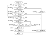
- FIG. 11 is a flowchart showing the initialization process for the torsion angle estimate in the front drive train.
- FIG. 12 is a flowchart showing the initialization process for the torsion angle estimate in the rear drivetrain.
- FIG. 13 is a graph showing longitudinal acceleration and the like in an electric vehicle of a comparative example.
- FIG. 14 is a graph showing the longitudinal acceleration and the like in the electric vehicle of this embodiment.
- FIG. 1 is a block diagram showing a schematic configuration of an electric vehicle 100.
- the electric vehicle 100 in this embodiment is an electric vehicle (EV) or a hybrid vehicle (HEV) equipped with one or more electric motors (hereinafter simply referred to as motors) as a driving source.
- the electric vehicle 100 in this embodiment includes a front drive system Sf and a rear drive system Sr.
- the front drive system Sf includes a drive motor 4 (hereinafter referred to as a front motor 4f or simply referred to as a motor 4f) that provides a driving force to the front drive wheels 9fR and 9fL.
- the rear drive system Sr includes a drive motor 4 (hereinafter referred to as a rear motor 4r or simply referred to as a motor 4r) that provides a driving force to the rear drive wheels 9rR and 9rL.
- Battery 1 is composed of a secondary battery that can supply (discharge) drive power when each motor 4f, 4r is in powered operation and can receive (charge) regenerative power when in regenerative operation.
- the controller 2 is a control device for the electric vehicle 100. That is, the controller 2 comprehensively controls each part constituting the electric vehicle 100. For example, signals indicating various vehicle variables such as the vehicle speed V, the accelerator opening A PO , the rotor phases ⁇ f and ⁇ r of the motors 4f and 4r, and the motor currents i f and i r that are currents flowing through the motors 4f and 4r are input as digital signals to the controller 2.
- the controller 2 generates a PWM (Pulse Width Modulation) signal for controlling the motors 4f and 4r based on the input signals.
- the controller 2 generates a drive signal for the inverters 3f and 3r in response to the generated PWM signal.
- the inverters 3f, 3r turn on/off two switching elements provided for each phase in response to the drive signal generated by the controller 2. As a result, the inverters 3f, 3r convert the direct current supplied from the battery 1 into alternating current and pass the desired current through the motors 4f, 4r.
- the switching elements of the inverters 3f, 3r are composed of power semiconductor elements such as insulated gate bipolar transistors (IGBTs) and metal oxide semiconductor field effect transistors (MOS-FETs).
- the motors 4f, 4r generate driving force by AC current supplied from the inverters 3f, 3r, and transmit the driving force to the drive wheels 9fR, 9fL, 9rR, 9rL via a driving force transmission system including the speed reducers 5f, 5r and the drive shafts DSf , DSr .
- the motors 4f, 4r also recover the kinetic energy of the electric vehicle 100 as electric energy by so-called regenerative control.
- the inverter 3 converts the AC current generated by the motors 4f, 4r into DC current and supplies it to the battery 1.
- the current sensors 20f, 20r detect currents i f , i r of the motors 4f, 4r.
- the current i f is, for example, three-phase AC currents i uf , i vf , and i wf of the front motor 4f.
- the current i r is, for example, three-phase AC currents i ur , i vr , and i wr of the rear motor 4r. Note that if the currents of any two phases of the three-phase AC current are detected, the current of the remaining phase can be calculated.
- the rotation sensors 21f and 21r are, for example, resolvers or encoders, and detect rotor phases ⁇ f and ⁇ r of the motors 4f and 4r.
- FIG. 2 is a flowchart showing the basic control of the electric vehicle 100.
- the controller 2 is programmed to repeatedly execute the control of each step shown in FIG. 2 at a predetermined cycle.
- step S201 the controller 2 executes input processing. Specifically, the controller 2 receives signals indicating the above-mentioned various vehicle conditions as vehicle information.
- the signals indicating the vehicle conditions include, for example, the vehicle speed V, the accelerator opening A PO , the rotor phases ⁇ f and ⁇ r , the angular velocities ⁇ mf and ⁇ mr of the motors 4 f and 4 r , the currents i f and i r flowing through the motors 4 f and 4 r , and the DC voltage V dc of the battery 1.
- the vehicle speed V (km/h) is acquired by communication from other controllers such as a meter or a brake controller.
- the controller 2 can also calculate the vehicle speed V (km/h).
- the controller 2 obtains the vehicle speed v (m/s) by multiplying the mechanical angular velocity of the front motor 4f or rear motor 4r by the tire dynamic radius r and dividing it by the gear ratio of the final gear, and then multiplies this by 3600/1000 to convert the unit, thereby calculating the vehicle speed V (km/h).
- the accelerator opening A PO (%) is obtained from an accelerator opening sensor (not shown) or from another controller (not shown), such as a vehicle controller.
- the rotor phases ⁇ f and ⁇ r (rad) are acquired from the rotation sensors 21f and 21r.
- the controller 2 calculates the angular velocities ⁇ mf and ⁇ mr of the motors 4f and 4r based on the rotor phases ⁇ f and ⁇ r .
- the motor currents i f and i r (A) are acquired from a current sensor 20.
- the DC voltage V dc (V) is detected by a voltage sensor (not shown) provided on a DC power supply line between the battery 1 and the inverter 3. Note that the power supply voltage value obtained by a battery controller (not shown) may be acquired as the DC voltage V dc (V).
- the controller 2 executes a basic target torque calculation process.
- the basic target torque calculation process includes a target torque calculation process and a torque distribution process.
- the total target torque calculation process is a process for calculating a target torque command value T m0 * representing a torque (required torque) required of the electric vehicle 100 by the driver's operation of the accelerator pedal, etc.
- the torque distribution process is a process for distributing the target torque command value T m0 * to a front torque command value T mf0 * and a rear torque command value T mr0 * .
- the front torque command value T mf0 * is a command value (target value) for the torque to be generated by the front motor 4f (hereinafter referred to as the front torque T mf ).
- the rear torque command value T mr0 * is a command value (target value) for the torque to be generated by the rear motor 4r (hereinafter referred to as the rear torque T mr ).
- the controller 2 calculates the target torque command value T m0 * based on the accelerator opening A PO , the vehicle speed V, and the angular velocity ⁇ m .
- the controller 2 refers to the angular velocity ⁇ mf of the front motor 4f as the angular velocity ⁇ m for calculating the target torque command value T m0 * .
- the controller 2 has an accelerator opening-torque table in which the angular velocity ⁇ mf of the front motor 4f and the target torque command value T m0 * are associated in advance through experiments, simulations, or the like. Therefore, the controller 2 calculates the target torque command value T m0 * corresponding to the angular velocity ⁇ mf of the front motor 4f by referring to the accelerator opening-torque table.
- step S203 the controller 2 executes vibration suppression control (hereinafter, referred to as vibration suppression control S203).
- the vibration suppression control is a control for suppressing vibrations occurring in the driving force transmission system, such as torsional vibrations of the drive shaft.
- the controller 2 executes vibration suppression control for each of the front drive system Sf and the rear drive system Sr.
- the controller 2 calculates the front final torque command value Tmff * by compensating the front torque command value Tmf0 * so as to suppress the torsional vibrations of the front drive shaft DSf .
- the front final torque command value Tmff * is the final torque command value for the front motor 4f.
- the controller 2 calculates the rear final torque command value Tmrf * by compensating the rear torque command value Tmr0 * so as to suppress the torsional vibrations of the rear drive shaft DSr.
- the rear final torque command value Tmrf * is the final torque command value for the rear motor 4r. The vibration suppression control will be described in detail later.
- step S204 the controller 2 executes a current command value calculation process to calculate a d-axis current target value i df * and a q-axis current target value i qf * of the front motor 4 f and a d-axis current target value i dr * and a q-axis current target value i qr * of the rear motor 4 r.
- the controller 2 has a table in which the front final torque command value T mff * , the angular velocity ⁇ mf of the front motor 4f, and the DC voltage V dc are associated in advance with the d-axis current target value i df * and the q-axis current target value i qf * of the front motor 4f through experiments, simulations, etc.
- the controller 2 calculates the d-axis current target value i df * and the q-axis current target value i qf * (hereinafter referred to as dq-axis current target values i df * , i qf * ) based on the front final torque command value T mff * , the angular velocity ⁇ mf of the front motor 4f, and the DC voltage V dc.
- the controller 2 has a table in which the rear final torque command value Tmrf * , the angular velocity ⁇ mr of the rear motor 4r, and the DC voltage Vdc are associated in advance with the d-axis current target value idr * and the q-axis current target value iqr * of the rear motor 4r through experiments, simulations, etc. Therefore, by referring to this table, the controller 2 calculates the d-axis current target value idr * and the q-axis current target value iqr * of the rear motor 4r based on the rear final torque command value Tmrf * , the angular velocity ⁇ mr of the rear motor 4r , and the DC voltage Vdc .
- step S205 the controller 2 executes a current control calculation process.
- the current control is a process for generating a PWM signal based on the d-axis current target value and the q-axis current target value.
- the controller 2 calculates the d-axis current i df and the q-axis current i qf (hereinafter referred to as dq-axis current i df , i qf ) of the front motor 4 f based on the three - phase currents i uf , i vf , i wf and the rotor phase ⁇ f of the front motor 4 f.
- the controller 2 calculates the d-axis voltage command value V df * and the q-axis voltage command value V qf * (hereinafter referred to as dq-axis voltage command values V df * , V qf * ) of the front motor 4 f based on the deviation between the dq-axis currents i df , i qf and the dq-axis current target values i df * , i qf * .
- the controller 2 may apply so-called non-interference control when calculating the dq-axis voltage command values V df * , V qf * .
- the controller 2 calculates three-phase voltage command values V uf * , V vf * , V wf * for the front motor 4 f based on the d- and q-axis voltage command values V df * , V qf * and the rotor phase ⁇ f.
- the controller 2 then calculates a PWM signal based on the three-phase voltage command values V uf * , V vf * , V wf * and the DC voltage V dc .
- the front inverter 3 f is driven by this PWM signal, the front motor 4 f generates a front torque T mf according to the front final torque command value T mff * .
- the current control calculation process for the rear motor 4r is similar to that described above. That is, the controller 2 calculates the d-axis current i dr and the q-axis current i qr (referred to as dq-axis currents i dr , i qr ) of the rear motor 4r based on the three-phase currents i ur , i vr , and i wr and the rotor phase ⁇ r of the rear motor 4r.
- the controller 2 calculates the d-axis voltage command value V dr * and the q-axis voltage command value V qr * (hereinafter referred to as dq-axis voltage command values V dr * , V qr * ) of the rear motor 4r based on the deviation between the dq-axis currents i dr , i qr and the dq-axis current target values i dr * , i qr * .
- the controller 2 calculates a PWM signal based on the dq-axis voltage command values Vdr * , Vqr * and the rotor phase ⁇ r , the three-phase voltage command values Vur * , Vvr * , Vwr * of the rear motor 4r, and the DC voltage Vdc .
- the rear motor 4r When the rear inverter 3r is driven by this PWM signal, the rear motor 4r generates a rear torque Tmr according to the rear final torque command value Tmrf * .
- the vibration control (step S203) is explained in detail below.
- FIG. 5 is a block diagram showing the configuration of vibration suppression control S203. As shown in FIG. 5, vibration suppression control is realized by F/F compensation (feedforward compensation) S501, S503 and F/B compensation (feedback compensation) S502, S504.
- F/F compensation feedforward compensation
- S503 feedforward compensation
- F/B compensation feedback compensation
- the F/F compensation S501 and the F/B compensation S502 are configured to calculate the front final torque command value T mff * from the front torque command value T mf0 * .
- the angular velocity ⁇ mf of the front motor 4 f is used in addition to the front torque command value T mf0 * to calculate the front final torque command value T mff * .
- the angular velocity ⁇ mf is used in both the F/F compensation S501 and the F/B compensation S502.
- the F/F compensation S501 calculates a feedforward compensation torque command value (hereinafter referred to as F/F compensation torque command value) T mf1 * and an angular velocity estimated value ⁇ mf ⁇ based on the front torque command value T mf0 * .
- the F/F compensation torque command value T mf1 * is a torque command value that compensates in advance for the torsional vibration of the front drive shaft DS f by feedforward control.
- the angular velocity estimated value ⁇ mf ⁇ is an estimated value that represents the angular velocity ⁇ mf when the front motor 4 f is controlled according to the F/F compensation torque command value T mf1 * .
- the angular velocity ⁇ mf of the front motor 4f is used for initialization of parameters required in the calculation process of the F/F compensation torque command value Tmf1 * and the angular velocity estimated value ⁇ mf ⁇ .
- the parameter that requires initialization is the torsion angle ⁇ df of the front drive shaft DSf . This initialization process will be described in detail below together with the configuration of the F/F compensation S501.
- the F/B compensation S502 calculates a feedback compensation torque command value (hereinafter referred to as F/B compensation torque command value) Tmf2 * based on the angular velocity ⁇ mf of the front motor 4f and the angular velocity estimated value ⁇ mf ⁇ .
- the F/B compensation torque command value Tmf2 * is a torque command value that compensates for the torsional vibration of the front drive shaft DSf by feedback control that feeds back the angular velocity ⁇ mf .
- the configuration of the F/B compensation S502 will be described in detail later.
- the front final torque command value T mff * is calculated by adding the above-mentioned F/F compensation torque command value T mf1 * and F/B compensation torque command value T mf2 * .
- the F/F compensation S503 and the F/B compensation S504 are configured to calculate the rear final torque command value T mrf * from the rear torque command value T mr0 * .
- the F/F compensation S503 and the F/B compensation S504 are configured similarly to the F/F compensation S501 and the F/B compensation S502 for calculating the front final torque command value T mff * . Therefore, in this embodiment, in addition to the rear torque command value T mr0 * , the angular velocity ⁇ mr of the rear motor 4r is used to calculate the rear final torque command value T mrf * .
- the angular velocity ⁇ mr is used in both the F/F compensation S503 and the F/B compensation S502.
- the F/F compensation S503 calculates a feedforward compensation torque command value (hereinafter referred to as F/F compensation torque command value) T mr1 * and an angular velocity estimated value ⁇ mr ⁇ based on the rear torque command value T mr0 * .
- the F/F compensation torque command value T mr1 * is a torque command value that compensates in advance for torsional vibration of the rear drive shaft DSr by feedforward control.
- the angular velocity estimated value ⁇ mr ⁇ is an estimated value that represents the angular velocity ⁇ mr when the rear motor 4r is controlled according to the F/F compensation torque command value T mr1 * .
- the angular velocity ⁇ mr of the rear motor 4r is used to initialize parameters required in the calculation process of the F/F compensation torque command value Tmr1 * and the angular velocity estimated value ⁇ mr ⁇ .
- the parameter that requires initialization is the torsion angle ⁇ dr of the rear drive shaft DSr. This initialization process will be described in detail below together with the configuration of the F/F compensation S503.
- the F/B compensation S504 calculates a feedback compensation torque command value (hereinafter referred to as F/B compensation torque command value) T mr2 * based on the angular velocity ⁇ mr of the rear motor 4r and the angular velocity estimate value ⁇ mr ⁇ .
- the F/B compensation torque command value T mr2 * is a torque command value that compensates for the torsional vibration of the rear drive shaft DSr by feedback control that feeds back the angular velocity ⁇ mr .
- the configuration of the F/B compensation S504 will be described in detail later.
- Fig. 6 is a block diagram showing the configuration of F/F compensation S501 for the front drive train Sf .
- the F/F compensation S501 includes a compensation torque calculation S601, a vehicle model S602, and an initialization process S603.
- the compensation torque calculation S601 calculates an F/F compensation torque command value T mf1 * based on the front torque command value T mf0 * and the torsional angular velocity estimated value ⁇ df ⁇ .
- the torsional angular velocity estimated value ⁇ df ⁇ is an estimated value for the torsional angular velocity ⁇ df of the front drive shaft DS f , and is acquired from the vehicle model S602.
- the F/F compensation torque command value T mf1 * is calculated by subtracting the torsional angular velocity estimated value ⁇ df ⁇ multiplied by the gain k f1 from the front torque command value T mf0 * .
- the vehicle model S602 is a driving force transmission model of the front drive train Sf .
- the vehicle model S602 calculates an angular velocity estimate value ⁇ mf ⁇ based on the F/F compensation torque command value T mf1 * .
- a torsion angle estimate value ⁇ df ⁇ and a torsion angular velocity estimate value ⁇ df ⁇ of the front drive shaft DS f are calculated.
- the torsion angle estimate value ⁇ df ⁇ is an estimate of the torsion angle ⁇ df generated in the front drive shaft DS f when the front motor 4f is controlled according to the F/F compensation torque command value T mf1 * .
- the torsion angle estimate value ⁇ df ⁇ is calculated by integrating the torsion angular velocity estimate value ⁇ df ⁇ .
- the integrator that integrates the torsion angular velocity estimate value ⁇ df ⁇ may be initialized by the initialization process S603. That is, the torsion angle estimate value ⁇ df ⁇ may be initialized by the initialization process S603.
- the vehicle model S602 also includes a dead zone Bdf .
- the dead zone Bdf is a model of the backlash characteristics from the torque Tmf of the front motor 4f to the front drive shaft DSf .
- the vehicle model S602 calculates the angular velocity estimate ⁇ mf ⁇ , the torsional angular velocity estimate ⁇ df ⁇ , and the torsional angle estimate ⁇ df ⁇ with particular accuracy, taking into account the influence of the backlash generated in the front drive system Sf .
- the initialization process S603 initializes the torsion angle estimated value ⁇ df ⁇ based on the front torque command value T mf0 * and the angular velocity ⁇ mf of the front motor 4 f. More specifically, the initialization process S603 includes an initialization necessity determination process for determining whether or not initialization of the torsion angle estimated value ⁇ df ⁇ is necessary, and an initial value setting process for setting the value of the torsion angle estimated value ⁇ df ⁇ after initialization (hereinafter referred to as the initial value ⁇ df-ini ).
- the determination as to whether or not initialization is necessary is made based on the front torque command value T mf0 * .
- the front initialization timer ⁇ f-ini counts the time during which the front torque command value T mf0 * is substantially zero. Then, when the front initialization timer ⁇ f-ini becomes equal to or greater than a predetermined threshold value Th f and a value occurs in the front torque command value T mf0 * , it is determined that initialization is necessary. That is, it is determined that initialization is necessary when the front motor 4f is not substantially controlled and is driven by the electric vehicle 100 for a time equal to or greater than the threshold value Th f .
- the threshold value Th f is determined in advance by an experiment, a simulation, or the like.
- the result of the determination as to whether or not initialization is necessary is managed by the front initialization flag F f-ini .
- the front initialization flag F f-ini indicates that initialization is necessary by a value "1" and indicates that initialization is not necessary by a value "0". Therefore, the torsion angle estimated value ⁇ df ⁇ is initialized when the value of the front initialization flag F f-ini becomes "1".
- an initial value ⁇ df-ini of the torsion angle estimated value ⁇ df ⁇ is set based on the rotation direction of the front motor 4f.
- the rotation direction of the front motor 4f is determined by the sign of the angular velocity ⁇ mf .
- the rotation direction of the front motor 4f when the electric vehicle 100 is moved forward by the front torque T mf is defined as the positive direction, and the rotation direction opposite thereto is defined as the negative direction.
- FIG. 7 is a block diagram showing the configuration of F/F compensation S503 for the rear drivetrain Sr.
- the F/F compensation S503 is configured substantially similarly to the F/F compensation S501 for the front drivetrain Sf . That is, the F/F compensation S503 includes a compensation torque calculation S701, a vehicle model S702, and an initialization process S703.
- the compensation torque calculation S701 calculates an F/F compensation torque command value T mr1 * based on the rear torque command value T mr0 * and the torsional angular velocity estimated value ⁇ dr ⁇ .
- the torsional angular velocity estimated value ⁇ dr ⁇ is an estimated value for the torsional angular velocity ⁇ dr of the rear drive shaft DSr , and is acquired from the vehicle model S702.
- the F/F compensation torque command value T mr1 * is calculated by subtracting the torsional angular velocity estimated value ⁇ dr ⁇ multiplied by the gain k r1 from the rear torque command value T mr0 * .
- the vehicle model S702 is a driving force transmission model of the rear drivetrain Sr.
- the vehicle model S702 calculates an angular velocity estimated value ⁇ mr ⁇ based on the F/F compensation torque command value T mr1 * .
- a torsion angle estimate value ⁇ dr ⁇ and a torsion angular velocity estimate value ⁇ dr ⁇ of the rear drive shaft DSr are calculated.
- the torsion angle estimate value ⁇ dr ⁇ is an estimate of the torsion angle ⁇ dr generated in the rear drive shaft DSr when the rear motor 4r is controlled according to the F/F compensation torque command value Tmr1 * .
- the torsion angle estimate value ⁇ dr ⁇ is calculated by integrating the torsion angular velocity estimate value ⁇ dr ⁇ .
- the integrator that integrates the torsion angular velocity estimate value ⁇ dr ⁇ may be initialized by the initialization process S703. That is, the torsion angle estimate value ⁇ dr ⁇ may be initialized by the initialization process S703.
- the vehicle model S702 also includes a dead zone Bdr .
- the dead zone Bdr is a model of the backlash characteristics from the torque Tmr of the rear motor 4r to the rear drive shaft DSr .
- the vehicle model S702 calculates the angular velocity estimate ⁇ mr ⁇ , the torsional angular velocity estimate ⁇ dr ⁇ , and the torsional angle estimate ⁇ dr ⁇ with particular accuracy, taking into account the influence of the backlash generated in the rear drive system Sr.
- the initialization process S703 initializes the torsion angle estimated value ⁇ dr ⁇ based on the rear torque command value T mr0 * and the angular velocity ⁇ mr of the rear motor 4r. More specifically, the initialization process S703 includes an initialization necessity determination process for determining whether or not initialization of the torsion angle estimated value ⁇ dr ⁇ is necessary, and an initial value setting process for setting the value of the torsion angle estimated value ⁇ dr ⁇ after initialization (hereinafter referred to as the initial value ⁇ dr-ini ).
- the initialization necessity determination is made based on the rear torque command value T mr0 * .
- the rear initialization timer ⁇ r-ini counts the time during which the rear torque command value T mr0 * is substantially zero. Then, when the rear initialization timer ⁇ r-ini becomes equal to or greater than a predetermined threshold value Th r and a value occurs in the rear torque command value T mr0 * , it is determined that initialization is necessary. That is, it is determined that initialization is necessary when the rear motor 4r is not substantially controlled and is driven by the electric vehicle 100 for a time equal to or greater than the threshold value Th r .
- the threshold value Th r is determined in advance by an experiment, a simulation, or the like.
- the result of the initialization necessity determination is managed by a rear initialization flag F r-ini .
- the rear initialization flag F r-ini indicates that initialization is necessary by a value "1" and indicates that initialization is not necessary by a value "0". Therefore, the torsion angle estimated value ⁇ dr ⁇ is initialized when the value of the rear initialization flag F r-ini becomes "1".
- an initial value ⁇ dr -ini of the torsion angle estimated value ⁇ dr ⁇ is set based on the rotation direction of the rear motor 4r.
- the rotation direction of the rear motor 4r is determined by the sign of the angular velocity ⁇ mr .
- the rotation direction of the rear motor 4r when the electric vehicle 100 is moved forward by the rear torque T mr is defined as the positive direction, and the rotation direction opposite thereto is defined as the negative direction.
- FIG. 8 is an explanatory diagram showing a model of the driving force transmission system (vehicle models S602, S702).
- vehicle models S602, S702 vehicle models S602, S702.
- the vehicle model S602 of the front drive system Sf and the vehicle model S702 of the rear drive system Sr are substantially similar except for the systems to which they are applied. Therefore, in the following, the suffixes "f" representing front and “r” representing rear will be omitted from the parameters used in the description, and the vehicle models S602 and S702 will be described in common.
- the torsion angle ⁇ d is the torsion angle ⁇ df of the front drive shaft DSf in the front drive system Sf
- the equations of motion of the electric vehicle 100 are expressed by the following equations (1) to (6) for each drive system Sf , Sr.
- the transfer characteristics from the motor torque Tm to the motor angular velocity ⁇ m are expressed by the following equations (7) and (8) by Laplace transforming the above equations (1) to (6).
- the coefficients a3 , a2 , a1 , a0 , b3 , b2 , b1 , and b0 in equation (8) are each expressed by equation (9).
- H w (s) in formula (16) can be expressed by the following formula (17): Furthermore, the coefficients v 1 , v 0 , w 1 , and w 0 in formula (17) can be expressed by the following formula (18).
- formula (10) can be transformed into the following formula (19):
- ⁇ p is the damping coefficient of the driving force transmission system
- ⁇ p is the natural vibration frequency of the driving force transmission system.
- the F/F compensation torque command value Tm1 * is expressed by the following equation (22) using the target torque command value Tm0 * and gain k1 , the following equation (23) is obtained from equations (4) and (6).
- the gain k1 in equation (22) is a gain kf1 in the front drive system Sf and a gain kr1 in the rear drive system Sr.
- the drive shaft torque Td is expressed by the following equation (27) using the torsional stiffness Kd and torsional angle ⁇ d of the drive shaft, and the backlash amount ⁇ dead .
- the backlash amount ⁇ dead represents the overall backlash from the motor to the drive shaft. Therefore, the maximum positive value of the backlash is + ⁇ dead /2, the maximum negative value is - ⁇ dead /2, and the dead zone is in the range of - ⁇ dead /2 ⁇ ⁇ d ⁇ + ⁇ dead /2.
- the dead zone Bdf of the vehicle model S602 is expressed as - ⁇ deadf /2 ⁇ ⁇ df ⁇ ⁇ deadf /2 using the overall backlash amount ⁇ deadf from the front motor 4f to the front drive shaft DSf .
- the dead zone Bdr of the vehicle model S702 is expressed as - ⁇ deadr /2 ⁇ ⁇ dr ⁇ ⁇ deadr /2 using the overall backlash amount ⁇ deadr from the rear motor 4r to the rear drive shaft DSr .
- the torsion angle ⁇ d (torsion angle estimated value ⁇ df ⁇ , ⁇ dr ⁇ ) is calculated by integrating the torsion angular velocity ⁇ d (torsion angular velocity estimated value ⁇ df ⁇ , ⁇ dr ⁇ ) of the drive shaft, and the dead bands B df , B dr are applied to this torsion angle ⁇ d .
- the model of the dead bands B df , B dr functions correctly only when the torsion angle ⁇ d can be correctly estimated. In other words, when the torsion angle ⁇ d cannot be correctly estimated, backlash may cause shocks such as gear rattle noise and vibrations, even if the dead bands B df , B dr are introduced.
- the vehicle models S602 and S702 use the torque command values (F/F compensation torque command values Tmf1 * , Tmr1 * ) to calculate the torsional angular velocity ⁇ d and torsional angle ⁇ d of the drive shaft. Therefore, when the motors 4f and 4r are not substantially controlled and the torque command value continues to have no value ( Tmf1 * , Tmr1 * ⁇ 0), the vehicle models S602 and S702 cannot correctly estimate the torsional angle ⁇ d , etc. As a result, even if the dead zones Bdf and Bdr are introduced, a shock due to backlash may occur.
- the torsion angle estimated value ⁇ df ⁇ of the front drive shaft DSf becomes inaccurate when the electric vehicle 100 is substantially running in rear-wheel drive and the front motor 4f is rotated along with the electric vehicle 100. Therefore, when an attempt is made to generate torque with the front motor 4f thereafter, the dead zone B df cannot function correctly, and a shock due to backlash may occur in the front drive system Sf .
- the initialization processes S603 and S703 detect situations that are not anticipated in the vehicle models S602 and S702 as described above, and the torsion angle estimates ⁇ df ⁇ and ⁇ dr ⁇ are initialized appropriately. This reduces shock due to backlash even when the motors 4r, 4r that have been rotated by the electric vehicle 100 are to generate torque.
- FIG. 9 is a block diagram showing the configuration of the F/B compensation S502 for the front drive system Sf .
- the F/B compensation S502 calculates an F/B compensation torque command value Tmf2 * so as to reduce the deviation between the angular velocity ⁇ mf of the front motor 4f and its estimated value.
- the F/B compensation S502 uses a filter S901 to calculate an angular velocity estimate value ⁇ mf2 ⁇ corresponding to the F/B compensation torque command value T mf2 * . After that, the angular velocity estimate value ⁇ mf2 ⁇ and the angular velocity estimate value ⁇ mf ⁇ calculated by the vehicle model S602 are added to calculate a final angular velocity estimate value ⁇ mff ⁇ .
- the F/B compensation S502 passes the deviation between the angular velocity ⁇ mf of the front motor 4f and the final angular velocity estimate value ⁇ mff ⁇ through a filter S902 and multiplies it by a gain k f2 to calculate the F/B compensation torque command value T mf2 * .
- the filter S901 is formed by the transfer characteristic Gp (s) of the front drive system Sf .
- the filter S902 is formed by the inverse system of the transfer characteristic Gp (s) and a band-pass filter H(s).
- the gain kf2 is arranged to adjust the stability margin (gain margin, phase margin) of the feedback control system, and is set to a value of 1 or less.
- Fig. 10 is a block diagram showing the configuration of F/B compensation S504 for the rear drive system Sr.
- the F/B compensation S504 calculates an F/B compensation torque command value Tmr2 * so as to reduce the deviation between the angular velocity ⁇ mr of the rear motor 4r and its estimated value.
- the F/B compensation S504 is configured in the same manner as the F/B compensation S502.
- the F/B compensation S504 uses a filter S903 to calculate an angular velocity estimate value ⁇ mr2 ⁇ corresponding to the F/B compensation torque command value T mr2 * . After that, the angular velocity estimate value ⁇ mr2 ⁇ and the angular velocity estimate value ⁇ mr ⁇ calculated by the vehicle model S702 are added to calculate a final angular velocity estimate value ⁇ mrf ⁇ .
- the F/B compensation S504 passes the deviation between the angular velocity ⁇ mr of the rear motor 4r and the final angular velocity estimate value ⁇ mrf ⁇ through a filter 904 and multiplies it by a gain k r2 to calculate the F/B compensation torque command value T mr2 * .
- the filter S903 is formed by the transfer characteristic Gp (s) of the rear drive train Sr.
- the filter S904 is formed by the inverse system of the transfer characteristic Gp(s) and a band-pass filter H(s).
- the gain kr2 is arranged to adjust the stability margin (gain margin, phase margin) of the feedback control system, and is set to a value of 1 or less.
- the following describes the operation of the vibration suppression control S203 in the electric vehicle 100 configured as described above, and in particular the operation of the initialization processes S603 and S703 executed in the vibration suppression control S203.
- step S1101 the controller 2 determines whether or not the initialization of the torsion angle estimate ⁇ df ⁇ is required depending on whether or not the count value of the front initialization timer ⁇ f-ini is smaller than a threshold value Th f .
- the front initialization timer ⁇ f-ini counts the time during which the front torque command value T mf0 * is substantially zero. Therefore, when the front initialization timer ⁇ f-ini is smaller than the threshold value Th f , the front motor 4f is controlled to output the front torque T mf , and the torsion angle estimate value ⁇ df ⁇ of the front drive shaft DS f is correctly estimated by the vehicle model S602. Therefore, when the front initialization timer ⁇ f-ini is smaller than the threshold value Th f , the controller 2 determines that initialization of the torsion angle estimate value ⁇ df ⁇ is not necessary, and proceeds to step S1102.
- the front motor 4f is not controlled to output the front torque T mf , and the state in which the front motor 4f is rotated by the electric vehicle 100 continues. For this reason, the vehicle model S602 estimates that the torsion angle estimate ⁇ df ⁇ of the front drive shaft DS f is zero. However, since the front motor 4f is rotated by the electric vehicle 100, the actual torsion angle ⁇ df is the negative maximum value ( ⁇ deadf /2) or the positive maximum value (+ ⁇ deadf /2). Therefore, when the front initialization timer ⁇ f-ini is equal to or greater than the threshold Th f , the controller 2 determines that the torsion angle estimate ⁇ df ⁇ needs to be initialized, and proceeds to step S1107.
- step S1102 the controller 2 determines whether or not the front torque command value T mf0 * is substantially zero.
- the process proceeds to step S1103, where the controller 2 counts up the front initialization timer ⁇ f-ini .
- step S1104 the controller 2 checks whether or not the front initialization timer ⁇ f-ini has become equal to or greater than a threshold value Th f as a result of the count-up. In other words, the controller 2 checks whether or not it has become necessary to initialize the torsion angle estimated value ⁇ df ⁇ . Therefore, when the front initialization timer ⁇ f-ini has become equal to or greater than a threshold value Th f as a result of the count-up, the process proceeds to step S1107.
- step S1102 when the front torque command value T mf0 * has a significant value that is substantially not zero in step S1102, the process proceeds to step S1105, where the controller 2 resets (clears) the front initialization timer ⁇ f-ini . Also, in step S1106, the controller 2 resets (clears) the front initialization flag F f-ini . As a result, the torsion angle estimated value ⁇ df ⁇ of the front drive shaft DS f is not initialized, and the vibration suppression control S203 is executed.
- step S1104 if the front initialization timer ⁇ f-ini is smaller than the threshold value Th f , the process proceeds to step S1106, where the controller 2 resets (clears) the front initialization flag F f-ini . Therefore, the torsion angle estimate ⁇ df ⁇ of the front drive shaft DS f is not initialized, and the vibration suppression control S203 is executed. However, the front initialization timer ⁇ f-ini is not reset.
- step S1107 the controller 2 confirms that the front torque command value T mf0 * has a significant value that is not substantially zero. If the front torque command value T mf0 * is substantially zero in step S1107, the process proceeds to step S1106, where the controller 2 resets the front initialization flag F f-ini and executes the vibration suppression control S203 without initializing the torsion angle estimated value ⁇ df ⁇ .
- step S1108 the controller 2 further checks the rotation direction of the front motor 4f. That is, when attempting to cause the front motor 4f that has been rotated by the electric vehicle 100 to output the front torque T mf , in step S1108, the controller 2 checks the rotation direction of the front motor 4f based on its angular velocity ⁇ mf .
- step S1108 if the angular velocity ⁇ mf is equal to or greater than zero (non-negative value) and the rotation direction of the front motor 4f is positive, the process proceeds to step S1109, where the controller 2 sets the initial value ⁇ df-ini to the negative maximum value ( ⁇ deadf /2). On the other hand, in step S1108, if the angular velocity ⁇ mf is negative and the rotation direction of the front motor 4f is negative, the process proceeds to step S1110, where the controller 2 sets the initial value ⁇ df-ini to the positive maximum value (+ ⁇ deadf /2).
- the reason for setting in this manner is that when the front motor 4f is rotated by the electric vehicle 100, the front motor 4f and the front drive shaft DSf are engaged in a state in which a twist occurs in the front drive shaft DSf in a direction opposite to the rotation direction of the front motor 4f.
- the controller 2 resets the front initialization timer ⁇ f-ini in step S1111, and sets the front initialization flag F f-ini in step S1112. Therefore, the torsion angle estimated value ⁇ df ⁇ of the vehicle model S602 is initialized, and the vibration damping control S203 is started from a state in which the torsion angle estimated value ⁇ df ⁇ is set to the initial value ⁇ df-ini .
- FIG 12 is a flowchart showing the initialization process S703 of the torsion angle estimate ⁇ dr ⁇ in the rear drivetrain Sr. As shown in FIG 12, the initialization process S703 of the torsion angle estimate ⁇ dr ⁇ is configured similarly to the initialization process S603 of the torsion angle estimate ⁇ df ⁇ in the front drivetrain Sf .
- step S1201 the controller 2 determines whether or not the torsion angle estimated value ⁇ dr ⁇ needs to be initialized depending on whether or not the count value of the rear initialization timer ⁇ r-ini is smaller than a threshold value Th r .
- the rear initialization timer ⁇ r-ini counts the time during which the rear torque command value T mr0 * is substantially zero. Therefore, when the rear initialization timer ⁇ r-ini is smaller than the threshold value Th r , the rear motor 4r is controlled to output the rear torque T mr , and the torsion angle estimate value ⁇ dr ⁇ of the rear drive shaft DS r is correctly estimated by the vehicle model S702. Therefore, when the rear initialization timer ⁇ r-ini is smaller than the threshold value Th r , the controller 2 determines that initialization of the torsion angle estimate value ⁇ dr ⁇ is not necessary, and proceeds to step S1202.
- the vehicle model S702 estimates that the torsion angle estimated value ⁇ dr ⁇ of the rear drive shaft DS r is zero. However, since the rear motor 4r is rotated together with the electric vehicle 100, the actual torsion angle ⁇ dr is the negative maximum value, that is, ⁇ dead /2.
- the controller 2 determines that the torsion angle estimated value ⁇ dr ⁇ needs to be initialized, and proceeds to step S1207.
- step S1202 the controller 2 determines whether or not the rear torque command value T mr0 * is substantially zero.
- the process proceeds to step S1203, where the controller 2 counts up the rear initialization timer ⁇ r-ini .
- step S1204 the controller 2 checks whether or not the rear initialization timer ⁇ r-ini has become equal to or greater than a threshold value Th r as a result of the count-up. That is, the controller 2 checks whether or not initialization of the torsion angle estimated value ⁇ dr ⁇ is required. Therefore, when the rear initialization timer ⁇ r-ini has become equal to or greater than a threshold value Th r as a result of the count-up, the process proceeds to step S1207.
- step S1202 when the rear torque command value T mr0 * has a significant value that is substantially not zero in step S1202, the process proceeds to step S1205, where the controller 2 resets (clears) the rear initialization timer ⁇ r-ini . Also, in step S1206, the controller 2 resets (clears) the rear initialization flag F r-ini . As a result, the torsion angle estimated value ⁇ dr ⁇ of the rear drive shaft DS r is not initialized, and vibration suppression control S203 is executed.
- step S1204 if the rear initialization timer ⁇ r-ini is smaller than the threshold value Th r , the process proceeds to step S1206, where the controller 2 resets (clears) the rear initialization flag F r-ini . Therefore, the torsion angle estimate ⁇ dr ⁇ of the rear drive shaft DS r is not initialized, and vibration suppression control S203 is executed. However, the rear initialization timer ⁇ r-ini is not reset.
- step S1201 or step S1204 the controller 2 confirms that the rear torque command value T mr0 * has a significant value that is not substantially zero. If the rear torque command value T mr0 * is substantially zero in step S1207, the process proceeds to step S1206, where the controller 2 resets the rear initialization flag F r-ini and executes the vibration damping control S203 without initializing the torsion angle estimated value ⁇ dr ⁇ .
- step S1208 the controller 2 further checks the rotation direction of the rear motor 4r. That is, when attempting to output the rear torque T mr from the rear motor 4r that has been rotated by the electric vehicle 100, in step S1208, the controller 2 checks the rotation direction of the rear motor 4r from its angular velocity ⁇ mr .
- step S1208 if the angular velocity ⁇ mr is equal to or greater than zero (non-negative value) and the rotation direction of the rear motor 4r is positive, the process proceeds to step S1209, where the controller 2 sets the initial value ⁇ dr-ini to the negative maximum value ( ⁇ deadr /2). On the other hand, in step S1208, if the angular velocity ⁇ mr is negative and the rotation direction of the rear motor 4r is negative, the process proceeds to step S1210, where the controller 2 sets the initial value ⁇ dr-ini to the positive maximum value (+ ⁇ deadf /2).
- the reason for setting in this manner is that when the rear motor 4r is rotated by the electric vehicle 100, the rear motor 4r and the rear drive shaft DS r are engaged with each other in a state in which a twist in the opposite direction to the rotation direction of the rear motor 4r is generated in the rear drive shaft DS r .
- the controller 2 resets the rear initialization timer ⁇ r-ini in step S1211, and sets the rear initialization flag F r-ini in step S1212. Therefore, the torsion angle estimated value ⁇ dr ⁇ of the vehicle model S702 is initialized, and the vibration damping control S203 is started from a state in which the torsion angle estimated value ⁇ dr ⁇ is set to the initial value ⁇ dr-ini .
- the operation of the initialization process S703 will be explained using as an example a driving scene in which the vehicle is constantly driving in front-wheel drive mode using the front motor 4f, and then, midway through, the rear motor 4r is additionally driven to transition to four-wheel drive driving and accelerate.
- FIG. 13(A) shows the front torque command value T mf0 * in the comparative example.
- FIG. 13(B) shows the rear torque command value T mr0 * in the comparative example.
- FIG. 13(C) shows the front final torque command value T mff * in the comparative example.
- FIG. 13(D) shows the rear final torque command value T mrf * in the comparative example.
- FIG. 13(E) shows the longitudinal acceleration A L of the electric vehicle in the comparative example.
- FIG. 13(F) shows the torsion angle estimate value ⁇ d ⁇ of each drive shaft in the comparative example.
- FIG. 13(F) shows the torsion angle estimate value ⁇ df ⁇ of the front drive shaft DS f
- the solid line in FIG. 13(F) shows the torsion angle estimate value ⁇ dr ⁇ of the rear drive shaft DS r
- the horizontal axis is time.
- the torsion angle estimate ⁇ dr ⁇ of the rear drive shaft DSr is zero until time t1 , and it is estimated that the torsion angle estimate ⁇ dr ⁇ will increase after time t1 .
- the rear motor 4r is rotated by the electric vehicle 100. Therefore, in reality, the torsion angle ⁇ dr of the rear drive shaft DSr is not zero, and the gears of the rear drive system Sr are engaged in the negative direction. Therefore, in the comparative example, the torsion angle estimate ⁇ dr ⁇ calculated by the vehicle model S702 of the rear drive system Sr deviates from the actual torsion angle ⁇ dr .
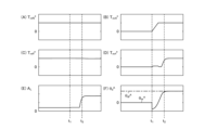
- FIG 14 is a graph showing the longitudinal acceleration AL etc. in the electric vehicle 100 of this embodiment.
- the electric vehicle 100 of this embodiment performs the initialization processes S603 and S703 as necessary when performing the vibration damping control S203.
- FIG. 14(A) shows the front torque command value T mf0 * in this embodiment.
- FIG. 14(B) shows the rear torque command value T mr0 * in this embodiment.
- FIG. 14(C) shows the front final torque command value T mff * in this embodiment.
- FIG. 14(D) shows the rear final torque command value T mrf * in this embodiment.
- FIG. 14(E) shows the longitudinal acceleration A L of the electric vehicle in this embodiment.
- FIG. 14(F) shows the torsion angle estimate value ⁇ d ⁇ of each drive shaft DS f , DS r in this embodiment.
- FIG. 14(F) shows the torsion angle estimate value ⁇ df ⁇ of the front drive shaft DS f
- the solid line in FIG. 14(F) shows the torsion angle estimate value ⁇ dr ⁇ of the rear drive shaft DS r
- the horizontal axis is time.
- the torsion angle estimate ⁇ df ⁇ of the front drive shaft DSf is estimated to be constant. Since the front motor 4f is in a controlled state, the torsion angle estimate ⁇ df ⁇ is correctly estimated.
- the control method for an electric vehicle is a method for controlling an electric vehicle that calculates a torque command value ( Tm * ) that commands the torque ( Tm ) to be generated by the drive motor (4), calculates a torsion angle ( ⁇ d ) that occurs in the drive shaft of the motor (4) when the motor (4) is driven in accordance with the torque command value (Tm * ), compensates the torque command value ( Tm * ) in accordance with the torsion angle ( ⁇ d), and controls the motor (4) based on a compensation torque command value ( Tm1 * ) that is the compensated torque command value.
- the electric vehicle (100) has two motors (4f, 4r), and compensation torque command values ( Tmf1 * , Tmr1 * ) are calculated for each of the motors (4f, 4r), and the two motors (4f, 4r) are each controlled in accordance with the respective compensation torque command values ( Tmf1 * , Tmr1 * ).
- the torsion angle estimated (calculated) for the vibration suppression control S203 is initialized. This eliminates the discrepancy between the estimated torsion angle and the actual torsion angle in the vibration suppression control S203. As a result, it is possible to reduce shock due to backlash even when attempting to generate torque with the co-rotating motor.
- the time ( ⁇ r-ini ) during which the torque command value (T mr0 * ) for the other motor (4r) is zero is counted, and when this time ( ⁇ r-ini ) becomes equal to or exceeds a predetermined threshold value (Thr r ) and a value is generated in the torque command value (T mr0 * ) for the other motor (4r), it is determined that initialization is necessary.
- an initial value ( ⁇ dr-ini ), which is the value of the torsion angle ( ⁇ dr ⁇ ) after initialization, is set based on the rotation direction of the other motor ( 4r ).
- the initial values ⁇ df-ini , ⁇ dr- ini of the torsion angle estimates ⁇ df ⁇ , ⁇ dr ⁇ can be easily and accurately set for each drivetrain S f , S r using only information related to the rotation direction of the motor, without using complex vehicle characteristics involving two motors.
- the initial values ⁇ df-ini , ⁇ dr- ini of the torsion angle estimates ⁇ df ⁇ , ⁇ dr ⁇ can be easily and accurately set for each drivetrain S f , S r using only information related to the rotation direction of the motor, without using complex vehicle characteristics involving two motors.
- the initial value ( ⁇ dr-ini ) when the rotation direction of the other motor (4r) is positive, the initial value ( ⁇ dr-ini ) is set to the negative maximum value (- ⁇ deadr /2), and when the rotation direction of the other motor (4r) is negative, the initial value ( ⁇ dr-ini ) is set to the positive maximum value (+ ⁇ deadr /2).
- the gears mesh in the direction opposite to the rotation direction of the motor. Therefore, as described above, by setting the initial values ⁇ df -ini , ⁇ dr -ini of the torsion angle estimated values ⁇ df ⁇ , ⁇ dr ⁇ to negative or positive maximum values depending on whether the rotation direction of the motor is positive or negative, the initial values ⁇ df -ini , ⁇ dr-ini of the torsion angle estimated values ⁇ df ⁇ , ⁇ dr ⁇ can be set simply and accurately. As a result, even when an attempt is made to generate torque with a motor that has been rotated, it is possible to simply and accurately reduce shock due to backlash.
- the control device for an electric vehicle in the above embodiment is a control device (2) for an electric vehicle ( 100 ) that calculates a torque command value ( Tm * ) that commands the torque ( Tm ) to be generated by the drive motor ( 4 ), calculates a torsion angle ( ⁇ d ) that occurs in the drive shaft of the motor (4) when the motor (4) is driven in accordance with the torque command value ( Tm * ), compensates the torque command value ( Tm * ) in accordance with the torsion angle ( ⁇ d ), and controls the motor (4) based on a compensation torque command value ( Tm1 * ), which is the compensated torque command value (Tm*).
- control device (2) for an electric vehicle (100), when the electric vehicle (100) has two motors (4f, 4r), the control device (2) calculates compensation torque command values ( Tmf1 * , Tmr1 * ) for each of the motors (4f, 4r) and controls the two motors (4f, 4r) according to their respective compensation torque command values ( Tmf1 * , Tmr1 * ).
- the control device (2) initializes the torsion angle ( ⁇ dr ⁇ ) calculated for the drive shaft ( DSr ) of the other motor (4) based on the direction of rotation of the other motor (4).
- the controller 2 of the electric vehicle 100 which performs vibration suppression control S203 for each of the two motors, initializes the torsion angle estimated (calculated) for the vibration suppression control S203 when attempting to generate torque from the co-rotating motor. This eliminates the discrepancy between the estimated torsion angle and the actual torsion angle in the vibration suppression control S203. As a result, it is possible to reduce shock due to backlash even when attempting to generate torque from the co-rotating motor.
Landscapes
- Engineering & Computer Science (AREA)
- Power Engineering (AREA)
- Transportation (AREA)
- Mechanical Engineering (AREA)
- Life Sciences & Earth Sciences (AREA)
- Sustainable Development (AREA)
- Sustainable Energy (AREA)
- Electric Propulsion And Braking For Vehicles (AREA)
Abstract
Selon la présente invention, une valeur de commande de couple destinée à commander un couple qui devrait être généré par un moteur pour la conduite est calculée; un angle de torsion se produisant dans un arbre d'entraînement du moteur lorsque le moteur est entraîné selon la valeur de commande de couple est calculé; la valeur de commande de couple est soumise à une compensation en fonction de l'angle de torsion; et le moteur est commandé sur la base d'une valeur de couple compensée, qui est la valeur de commande de couple ayant subi la compensation. Avec ce procédé de commande de véhicule électrique, lorsque le véhicule électrique comprend deux moteurs, des valeurs de commande de couple compensées sont calculées pour chacun des moteurs, respectivement, et les deux moteurs sont chacun commandés en fonction des valeurs de commande de couple compensées respectives. En outre, si, en raison d'un moteur parmi les deux moteurs entraînant le véhicule électrique, une rotation entraînée de l'autre moteur par le véhicule électrique s'est produite, l'angle de torsion calculé concernant l'arbre d'entraînement de l'autre moteur est initialisé sur la base de la direction de rotation de l'autre moteur lorsque le couple est ensuite amené à être généré par l'autre moteur.
Priority Applications (1)
| Application Number | Priority Date | Filing Date | Title |
|---|---|---|---|
| PCT/JP2023/001572 WO2024154302A1 (fr) | 2023-01-19 | 2023-01-19 | Procédé de commande de véhicule électrique et dispositif de commande de véhicule électrique |
Applications Claiming Priority (1)
| Application Number | Priority Date | Filing Date | Title |
|---|---|---|---|
| PCT/JP2023/001572 WO2024154302A1 (fr) | 2023-01-19 | 2023-01-19 | Procédé de commande de véhicule électrique et dispositif de commande de véhicule électrique |
Publications (1)
| Publication Number | Publication Date |
|---|---|
| WO2024154302A1 true WO2024154302A1 (fr) | 2024-07-25 |
Family
ID=91955532
Family Applications (1)
| Application Number | Title | Priority Date | Filing Date |
|---|---|---|---|
| PCT/JP2023/001572 Ceased WO2024154302A1 (fr) | 2023-01-19 | 2023-01-19 | Procédé de commande de véhicule électrique et dispositif de commande de véhicule électrique |
Country Status (1)
| Country | Link |
|---|---|
| WO (1) | WO2024154302A1 (fr) |
Citations (2)
| Publication number | Priority date | Publication date | Assignee | Title |
|---|---|---|---|---|
| WO2016021059A1 (fr) * | 2014-08-08 | 2016-02-11 | 日産自動車株式会社 | Dispositif de commande de véhicule électrique et procédé de commande de véhicule électrique |
| WO2018220805A1 (fr) * | 2017-06-01 | 2018-12-06 | 日産自動車株式会社 | Procédé de commande pour véhicule électrique, et dispositif de commande |
-
2023
- 2023-01-19 WO PCT/JP2023/001572 patent/WO2024154302A1/fr not_active Ceased
Patent Citations (2)
| Publication number | Priority date | Publication date | Assignee | Title |
|---|---|---|---|---|
| WO2016021059A1 (fr) * | 2014-08-08 | 2016-02-11 | 日産自動車株式会社 | Dispositif de commande de véhicule électrique et procédé de commande de véhicule électrique |
| WO2018220805A1 (fr) * | 2017-06-01 | 2018-12-06 | 日産自動車株式会社 | Procédé de commande pour véhicule électrique, et dispositif de commande |
Similar Documents
| Publication | Publication Date | Title |
|---|---|---|
| EP3632733B1 (fr) | Procédé de commande pour véhicule électrique, et dispositif de commande | |
| EP3798044B1 (fr) | Dispositif de commande pour véhicule à moteur électrique et procédé de commande pour véhicule à moteur électrique | |
| JP6233420B2 (ja) | 電動車両の制御装置および電動車両の制御方法 | |
| JP6787410B2 (ja) | 電動車両の制御方法、及び、制御装置 | |
| JP6760401B2 (ja) | 電動車両の制御方法、及び、制御装置 | |
| JP2019103249A (ja) | 電動車両の制御方法、及び、制御装置 | |
| JP7540659B2 (ja) | 車両制御装置 | |
| CN115243924B (zh) | 电动车辆的控制方法及电动车辆的控制装置 | |
| JP2017046389A (ja) | 電動車両の制御装置 | |
| CN117836168B (zh) | 电动车辆的控制方法以及电动车辆的控制装置 | |
| JP2020162373A (ja) | 電動車両の制御方法及び制御装置 | |
| JP7326960B2 (ja) | 電動車両の制御方法および電動車両の制御装置 | |
| JP7803187B2 (ja) | 電動車両制御方法、及び、電動車両制御装置 | |
| JP2021175279A (ja) | 電動車両の制御方法、及び、電動車両の制御装置 | |
| JP2020205682A (ja) | 電動車両の制御方法、及び、制御装置 | |
| JP7779330B2 (ja) | 電動車両制御方法及び電動車両制御装置 | |
| WO2024154302A1 (fr) | Procédé de commande de véhicule électrique et dispositif de commande de véhicule électrique | |
| JP7735871B2 (ja) | 電動車両制御方法及び電動車両制御装置 | |
| JP6880674B2 (ja) | 電動車両の制御方法、及び、電動車両の制御装置 | |
| JP7718262B2 (ja) | 電動車両の制御方法、及び、電動車両の制御装置 | |
| JP7596773B2 (ja) | 電動車両の制御方法及び制御装置 | |
| JP7754436B2 (ja) | 車両の制御装置及び車両の制御方法 |
Legal Events
| Date | Code | Title | Description |
|---|---|---|---|
| 121 | Ep: the epo has been informed by wipo that ep was designated in this application |
Ref document number: 23917515 Country of ref document: EP Kind code of ref document: A1 |
|
| NENP | Non-entry into the national phase |
Ref country code: DE |
|
| 122 | Ep: pct application non-entry in european phase |
Ref document number: 23917515 Country of ref document: EP Kind code of ref document: A1 |
|
| NENP | Non-entry into the national phase |
Ref country code: JP |