WO2024154367A1 - Structure de squelette pour un véhicule - Google Patents
Structure de squelette pour un véhicule Download PDFInfo
- Publication number
- WO2024154367A1 WO2024154367A1 PCT/JP2023/021794 JP2023021794W WO2024154367A1 WO 2024154367 A1 WO2024154367 A1 WO 2024154367A1 JP 2023021794 W JP2023021794 W JP 2023021794W WO 2024154367 A1 WO2024154367 A1 WO 2024154367A1
- Authority
- WO
- WIPO (PCT)
- Prior art keywords
- vehicle
- side sill
- connection portion
- intermediate connection
- strength
- Prior art date
- Legal status (The legal status is an assumption and is not a legal conclusion. Google has not performed a legal analysis and makes no representation as to the accuracy of the status listed.)
- Ceased
Links
Images

Classifications
-
- B—PERFORMING OPERATIONS; TRANSPORTING
- B62—LAND VEHICLES FOR TRAVELLING OTHERWISE THAN ON RAILS
- B62D—MOTOR VEHICLES; TRAILERS
- B62D29/00—Superstructures, understructures, or sub-units thereof, characterised by the material thereof
- B62D29/007—Superstructures, understructures, or sub-units thereof, characterised by the material thereof predominantly of special steel or specially treated steel, e.g. stainless steel or locally surface hardened steel
-
- B—PERFORMING OPERATIONS; TRANSPORTING
- B62—LAND VEHICLES FOR TRAVELLING OTHERWISE THAN ON RAILS
- B62D—MOTOR VEHICLES; TRAILERS
- B62D25/00—Superstructure or monocoque structure sub-units; Parts or details thereof not otherwise provided for
- B62D25/02—Side panels
-
- B—PERFORMING OPERATIONS; TRANSPORTING
- B62—LAND VEHICLES FOR TRAVELLING OTHERWISE THAN ON RAILS
- B62D—MOTOR VEHICLES; TRAILERS
- B62D27/00—Connections between superstructure or understructure sub-units
- B62D27/02—Connections between superstructure or understructure sub-units rigid
- B62D27/023—Assembly of structural joints
-
- B—PERFORMING OPERATIONS; TRANSPORTING
- B62—LAND VEHICLES FOR TRAVELLING OTHERWISE THAN ON RAILS
- B62D—MOTOR VEHICLES; TRAILERS
- B62D25/00—Superstructure or monocoque structure sub-units; Parts or details thereof not otherwise provided for
- B62D25/02—Side panels
- B62D25/025—Side sills thereof
Definitions
- This disclosure relates to the skeletal structure of a vehicle.
- the body of a passenger car which is one type of vehicle, typically has a center pillar that is arranged along the vertical direction of the body, and a side sill that is connected to the lower part of the center pillar and arranged along the longitudinal direction of the body (see, for example, Patent Document 1).
- the center pillar and the side sill work together to receive the impact load, absorbing the impact and protecting the occupants in the cabin.
- Cited Document 1 In the event of a side collision, the smaller the amount of intrusion of the vehicle body material into the cabin, the higher the occupant protection performance. However, in the configuration described in Cited Document 1, a weak part is formed in the side sill so that in the event of a side collision, either the front or rear part of the lower part of the vehicle body relative to the center pillar deforms more toward the inside of the vehicle body than the other part. This results in a larger amount of intrusion at the location where this weak part is formed.
- One of the objectives of this disclosure is to provide a vehicle frame structure that can reduce the maximum amount of penetration of the side of the vehicle body into the interior of the vehicle during a side collision.
- This disclosure focuses on the vehicle frame structure described below.
- a first framework member disposed along a side portion of a vehicle in a front-rear direction; a restraining portion that restrains an end portion of the first framework member in a longitudinal direction;
- a vehicle frame structure including: a second frame member arranged along a direction intersecting the longitudinal direction, the first framework member includes an intermediate connection portion to which the second framework structure is connected at an intermediate portion in the front-rear direction, and an end connection portion to which the restraint portion is connected, the first framework member has a first portion extending on both sides of the intermediate connection portion and a second portion located on the end connection portion side of the first portion,
- a vehicle frame structure wherein the torsional strength of the second portion is lower than the torsional strength of the first portion.
- a vehicle frame structure according to any one of (1) to (4), in which the plate thickness of the second portion is smaller than the plate thickness of the first portion.
- This disclosure makes it possible to reduce the maximum amount of penetration of the side of the vehicle body into the vehicle interior during a side collision.
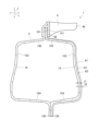
- FIG. 1 is a schematic left side view showing a main portion of a vehicle body to which a vehicle body structure according to an embodiment of the present disclosure is applied.
- FIG. 2 is a cross-sectional view of the side sill taken along line II-II in FIG. 1, the cross-sectional view being perpendicular to the front-rear direction.
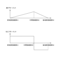
- FIG. 3 is a diagram showing bending moment and torsional moment input to a side sill during a side collision of a vehicle.
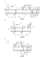
- Fig. 4(A) is a diagram showing a main part of a first modified example of the present disclosure
- Fig. 4(B) is a diagram showing a main part of a second modified example
- Fig. 4(C) is a diagram showing a main part of a third modified example.
- a side collision of the vehicle refers to a side collision in which the connection between the side sill and the center pillar is the collision position.
- the side sill and the center pillar have the role of protecting the cabin during a side collision while deforming so as not to lead to damage to the occupants.
- the side sill is made by press-molding a single plate, so that the side sill has a structure with the same strength and plate thickness in the longitudinal direction.
- the bending moment of the side sill is maximum at the connection position of the side sill with the center pillar, that is, in the vicinity directly below the occupant of the front seat, so that the vehicle body is likely to be greatly bent at the connection position.
- the amount of penetration of each vehicle body member, such as the center pillar inner and the door inner, into the cabin becomes large.
- the present inventor came up with the idea that, in the event of a side collision, by torsionally deforming a portion of the side sill that is distant from the connection position with the center pillar to a certain extent, it is possible to reduce the amount of intrusion of the entire vehicle body, including the connection position between the side sill and the center pillar, into the cabin.
- the inventor then considered a configuration in which the torsion strength of the front or rear of the side sill is partially reduced, thereby causing torsion deformation at the portion with reduced torsion strength.
- the present disclosure was arrived at, which makes it possible to reduce deformation of the vehicle body at the connection position between the side sill and the center pillar, thereby reducing the amount of intrusion of the entire side member into the cabin in the event of a side collision.
- FIG. 1 is a schematic left side view showing a main part of a vehicle body 1 to which a vehicle body structure according to an embodiment of the present disclosure is applied.
- FIG. 2 is a cross-sectional view of a side sill 5 taken along line II-II in FIG. 1 and perpendicular to the fore-aft direction X.
- the vehicle body 1 is a part of a vehicle, and an example of the vehicle can be an automobile.
- An example of an automobile can be a passenger car.
- Examples of the passenger car can be a sedan type passenger car, a coupe type passenger car, a hatchback type passenger car, a minivan type passenger car, an SUV (Sport Utility Vehicle) type passenger car, etc.
- the vehicle length direction, vehicle width direction, and vehicle height direction are referred to as the fore-and-aft direction X, the vehicle width direction Y, and the up-and-down direction Z, respectively.
- the vehicle body 1 is formed using a steel plate having a predetermined thickness.
- the steel plate include plated steel plates such as aluminum-plated steel plates and zinc-plated steel plates.
- examples of the steel plate include dual-phase steel plates containing martensite and ferrite.
- the steel plate may be a steel plate other than a dual-phase steel plate, and the specific type is not limited.
- the vehicle body 1 may be made of aluminum alloy plate, or may have both parts made of aluminum alloy plate and parts made of steel plate. Also, the whole or part may be made of a laminated material made of two or more of iron, aluminum, and resin.
- the vehicle body 1 has a front pillar 2, a roof pillar 3, a center pillar 4, a side sill 5, and a side sill rear 6.
- the front pillar 2 has a cross section perpendicular to the longitudinal direction of the front pillar 2 that is formed into a closed shape such as a rectangle.
- the front pillar 2 has a pillar upper 11 that is connected to the roof pillar 3 toward the rear as it moves upward, and a pillar lower 12 that is disposed below the pillar upper 11.
- the pillar lower 12 is formed, for example, into an L shape in a side view.
- the lower rear edge 12a of the pillar lower 12 opens toward the rear.
- This lower rear edge 12a has a front restraining portion 21 that restrains the front end of the side sill 5 by joining the front end of the side sill 5 by welding or bonding.
- the side sill 5 extends rearward from the front restraining portion 21 of the front pillar 2.
- the side sill rear 6 is disposed behind the side sill 5.
- the side sill rear 6 is a hollow member disposed along the front-rear direction X.
- the cross section of the side sill rear 6 perpendicular to the longitudinal direction of the side sill rear 6 is formed into a closed shape (closed cross-sectional shape) such as a rectangle.
- the front end edge 6a of the side sill rear 6 opens forward.
- This front end edge 6a has a rear restraining portion 22 that restrains the rear end of the side sill 5 by joining the rear end of the side sill 5 by welding or bonding.
- the side sill 5 extends forward from the rear restraining portion 22 of the side sill rear 6.
- the front restraint portion 21 and the rear restraint portion 22 restrain both longitudinal ends of the side sill 5.
- the roof pillar 3 is disposed on the roof portion of the vehicle body 1 and extends rearward from the pillar upper 11.
- the roof pillar 3 has a roof pillar outer disposed on the outside in the vehicle width direction Y, and a roof pillar outer disposed on the inside in the vehicle width direction Y relative to the roof pillar outer, and the cross-sectional shape perpendicular to the longitudinal direction of the roof pillar 3 is a closed cross-sectional shape.
- the center pillar 4 is an example of a second frame member that is arranged in a direction that intersects with the longitudinal direction of the side sill 5.
- the center pillar 4 is arranged behind the front pillar 2, and is arranged in the vertical direction Z from the roof pillar 3 to the side sill 5.
- the center pillar 4 has an outer pillar arranged on the outside in the vehicle width direction Y, and an inner pillar arranged on the inside in the vehicle width direction Y relative to the outer pillar, and its cross-sectional shape perpendicular to the vertical direction Z is a closed cross-sectional shape.
- the upper part 4a of the center pillar 4 is fixed to the middle part of the roof pillar 3 in the fore-and-aft direction X by welding, adhesive, etc.
- the lower part 4b of the center pillar 4 is joined to the middle part of the side sill 5 in the fore-and-aft direction X by welding, adhesive, etc.
- the side sill 5 is a first skeletal member arranged along the side of the vehicle in the fore-and-aft direction X, and in this embodiment, is provided at the lower part of the outer part of the vehicle body 1 in the vehicle width direction Y.
- the side sill 5 is connected to the lower part 4b of the center pillar 4 and arranged along the fore-and-aft direction X of the vehicle body 1.
- the side sill 5 forms an endless closed cross-sectional shape in a cross section perpendicular to the fore-and-aft direction X.
- the side sill 5 has a side sill outer 15 and a side sill inner 16 aligned in the vehicle width direction Y.
- the outer side sill 15 and the inner side sill 16 each have a hat-shaped cross section perpendicular to the front-rear direction X, and together they form a closed cross section of the side sill 5.
- the outer side sill 15 is positioned outside the inner side sill 16 in the vehicle width direction Y.
- the side sill outer 15 has an upper flange 151, an upper wall 152 extending outward from the upper flange 151 in the vehicle width direction Y, a side wall 153 extending downward from the upper wall 152, a lower wall 154 extending inward from the side wall 153 in the vehicle width direction Y, and a lower flange 155 extending downward from the lower wall 154.
- the side sill inner 16 has an upper flange 161, an upper wall 162 extending inward from the upper flange 161 in the vehicle width direction Y, a side wall 163 extending downward from the upper wall 162, a lower wall 164 extending outward from the side wall 163 in the vehicle width direction Y, and a lower flange 165 extending downward from the lower wall 164.
- the upper flanges 151, 161 are joined to each other by welding, adhesive, etc.
- the lower flanges 155, 165 are joined to each other by welding, adhesive, etc.
- the side sill 5 has an intermediate connection portion 50 to which the center pillar 4 is connected in the middle in the fore-and-aft direction X, and end connection portions 51, 52 that are connected to the restraint portions 21, 22.
- the intermediate connection portion 50 is a portion of the side sill 5 that is joined to the lower portion 4b of the center pillar 4 by welding or adhesive.
- the intermediate connection portion 50 is formed, for example, on the upper flanges 151, 161 of the side sill 5, and is in contact with the lower portion 4b of the center pillar 4.
- the intermediate connection portion 50 has a predetermined length in the front-rear direction X.
- the front end 50a of the intermediate connection portion 50 is in contact with the front end of the lower portion 4b of the center pillar 4.
- the rear end 50b of the intermediate connection portion 50 is in contact with the rear end of the lower portion 4b of the center pillar 4.
- the intermediate connection portion 50 is not limited to the upper flanges 151, 161 of the side sill 5, and may be provided in a portion of the side sill 5 other than the upper flanges 151, 161, such as the upper walls 152, 162 or the side walls 153, 163.
- the front end connection portion 51 is a portion that is joined to and fixed to the front restraint portion 21 of the pillar lower 12.
- the rear end connection portion 52 is a portion that is joined to and fixed to the rear restraint portion 22 of the side sill rear 6.
- the side sill 5 has a first portion 61 and a second portion 62 (621).
- the first portion 61 includes the intermediate connection portion 50 and extends on both the front and rear sides of the intermediate connection portion 50.
- the second portion 62 (621) is located on one of the end connection portions 51, 52 side with respect to the first portion 61, and has a torsional strength lower than the torsional strength of the first portion 61.
- the torsional strength refers to the strength when the side sill 5 is twisted around an axis along the fore-and-aft direction X.
- the first portion 61 and the second portion 62 are formed by the side sill outer 15 and the side sill inner 16, and are aligned in the fore-and-aft direction X.
- the second portion 62 constitutes the front portion of the side sill 5, including the front end connection portion 51.
- the first portion 61 constitutes the portion other than the second portion 62, and includes a part of the forward portion of the intermediate connection portion 50, the intermediate connection portion 50, and the rear portion of the intermediate connection portion 50.
- the first portion 61 includes the rear end connection portion 52.
- the side sill 5 When an object collides with the side sill 5 from the side, particularly when a side collision occurs between the center pillar 4 and the side sill 5 near the intermediate connection part 50, the side sill 5 receives an impact load from the object with the front restraint part 21 of the front pillar 2, the intermediate connection part 50, and the rear restraint part 22 as restraining positions. If the impact load is equal to or greater than a certain level, the side sill 5 absorbs the impact load by plastically deforming inward in the width direction Y.
- the intrusion of the side sill 5 and the center pillar 4 into the inside of the vehicle due to bending deformation and torsional deformation at the intermediate connection part 50 tends to be the largest among the intrusions of the vehicle body side parts.
- the second part 62 which has a lower torsional strength than the torsional strength of the first part 61, is provided away from the intermediate connection part 50.
- the torsional deformation in which the intermediate connection part 50 is deformed toward the inside of the vehicle can be suppressed. Therefore, the intrusion amount into the cabin 10 can be reduced near the intermediate connection part 50, where the intrusion amount into the cabin 10 tends to be the largest in the event of a side collision of the vehicle. As a result of being able to reduce the intrusion amount into the cabin side 10 at the location where the intrusion amount is the largest, the maximum intrusion amount of the vehicle body 1 into the cabin side in the event of a side collision of the vehicle can be reduced.
- the second portion 62 is provided in front of the intermediate connection portion 50.
- the second portion 62 only needs to be disposed away from the intermediate connection portion 50, and there are no specific limitations on its location. Note that the longer the distance Lb from the intermediate connection portion 50 to the second portion 62, the more the amount of torsional deformation of the side sill 5 and center pillar 4 near the intermediate connection portion 50, which is linked to the torsional deformation of the second portion 62, can be suppressed.
- Figure 3 is a diagram showing the bending moment and torsion moment input to the side sill 5 during a side collision of the vehicle.
- the distribution of bending moment and the distribution of torsion moment within the intermediate connection part 50 are omitted.
- the bending moment and torsion moment at each part are approximately constant.
- the bending moment input to the side sill 5 during a side collision of the vehicle is largest at the intermediate connection part 50 and becomes smaller as it approaches the front end connection part 51 and the rear end connection part 52.
- the positive and negative signs of the bending moment are reversed near the front end connection part 51 and the rear end connection part 52, but the absolute value of the bending moment is small. This is similar to the bending moment distribution when a point load is applied to a beam whose both ends are supported and fixed.
- the torsional moment input to the side sill 5 is small at the intermediate connection 50 (the connection with the center pillar 4) and is constant in other cross sections. This is similar to the torsional moment distribution when a torsion is applied to any point on a beam with fixed ends.
- the second portion 62 is provided so that, in the event of a side collision of the vehicle, deformation of the side sill 5 and center pillar 4 near the intermediate connection portion 50 occurs primarily due to bending moment, and torsional deformation of the second portion 62 occurs primarily due to torsion moment.
- the range of the second portion 62 it is preferable to not make the range of the second portion 62 too wide, since this can prevent excessive deformation of the second portion 62 due to bending moment.
- the strength of the first part 61 and the second part 62 can be set with reference to the fully plastic bending moment and the fully plastic torsional moment, and may also be set using concepts such as effective width, taking into account elastic buckling.
- the bending strength of the first portion 61 is Fb1
- the bending strength of the second portion 62 is Fb2
- the length of the second portion 62 in the front-rear direction X is La
- the distance from the end portion 62b of the second portion 62 on the intermediate connection portion 50 side to the intermediate connection portion 50 is Lb
- the following formula (1) is established.
- the above bending strength is a full plastic bending moment (full plastic moment).
- the denominator (La+Lb) of the right term of the above formula (1) indicates the distance from the intermediate connection part 50 to the end 62a of the second part 62 on the front end connection part 51 side.
- the left term of the above formula (1) indicates the ratio of the bending strength Fb2 of the second part 62 to the bending strength Fb1 of the first part 61.
- the ratio of the bending strength Fb2 of the second part 62 to the bending strength Fb1 of the first part 61 is higher than the ratio of the length La of the second part 62 to the distance La+Lb from the intermediate connection part 50 to the end 62a.
- the second part 62 also has a moderately large bending strength, so that during a side collision of the vehicle, the second part 62 is twisted while the amount of penetration of the second part 62 into the cabin 10 due to bending deformation (bending moment) is reduced.
- the amount of bending deformation in the second portion 62 can be suppressed while the amount of torsional deformation can be appropriately increased, and the impact load acting on the intermediate connection portion 50 can be released by the torsional deformation of the second portion 62.
- the impact load can be absorbed by the shear deformation of the upper walls 152, 162 of the side sill 5, so that the amount of bending deformation of the second portion 62 toward the cabin 10 due to the impact load can be reduced.
- the maximum amount of intrusion into the cabin 10 due to the impact load can be reduced in both the side sill 5 and the center pillar 4 near the intermediate connection portion 50 and the second portion 62. Since the second portion 62 is where the occupant's feet, for example, are located, the effect of protecting the occupant's feet can be enhanced by not causing a large intrusion amount due to bending.
- the boundary between the first portion 61 and the second portion 62 (weld portion 53 described later) is not straight in the height direction Z perpendicular to the front-rear direction X, it is preferable that the above formulas (1) and (2) hold in at least a portion of the height direction Z, and it is even more preferable that the above formulas (1) and (2) hold in the entire height direction Z.
- the second portion 62 extends to the front end connection portion 51. This allows the length of the second portion 62 to be sufficiently secured at a position farther from the intermediate connection portion 50. Therefore, the second portion 62 can be sufficiently twisted and deformed during a side collision of the vehicle to release the impact load from the intermediate connection portion 50, and the amount of intrusion of the side sill 5 and the center pillar 4 into the cabin 10 near the intermediate connection portion 50 can be suppressed.
- the second portion 62 does not need to include the front end connection portion 51.
- the front end connection portion 51 is formed by, for example, the first portion 61, and the first portion 61 and the second portion 62 are joined together. That is, the first portion 61, the second portion 62, and the first portion 61 are arranged in this order from the front side to the rear side, and the front first portion 61 may have the front restraint portion 21.
- one second portion 62 is disposed between the intermediate connection portion 50 and the front end connection portion 51. This simplifies the configuration of the side sill 5 including the first portion 61 and the second portion 62, and makes it easier to design the degree to which the second portion 62 promotes torsional deformation during a side collision of the vehicle to a desired value.
- the entire side sill inner 16, including the first portion 61 and the second portion 62, is formed from the same steel plate and has a uniform plate thickness, tensile strength, torsional deformation, and bending strength.
- the configuration of the side sill inner 16 in the first portion 61 is the same as the configuration of the side sill inner 16 in the second portion 62.
- the side sill inner 16 has a tensile strength of, for example, 980 MPa or more and a plate thickness of, for example, 0.8 mm to 2.0 mm. Note that the configuration of the side sill inner 16 in the first portion 61 and the configuration of the side sill inner 16 in the second portion 62 may be different.
- the configuration of the side sill outer 15 in the first portion 61 is different from the configuration of the side sill outer 15 in the second portion 62 so that the amount of intrusion of the side sill 5 and center pillar 4 into the cabin 10 during a side collision of the vehicle is reduced.
- the configuration of the side sill outer 15 will be described.
- the side sill outer 15 is formed using a tailored welded blank (TWB), so that the torsional strength of the second portion 62 is lower than the torsional strength of the first portion 61.
- TWB tailored welded blank
- the second portion 62 is disposed at the front end of the side sill 5, and the end portion 62b of the second portion 62 and the first portion 61 are joined by a weld portion 53 as a boundary portion.
- the weld portion 53 is a portion formed by laser welding or the like.
- the welded portion 53 may extend across the fracture line L that occurs when the first portion 61 and the second portion 62 are torsionally deformed and fracture.
- the fracture line L is shown by an imaginary two-dot chain line.
- the welded portion 53 is formed straight along the height direction Z.
- the tensile strength of the second portion 62 may be less than the tensile strength of the first portion 61. In this case, too, torsional deformation in the second portion 62 can be promoted during a side collision of the vehicle, allowing the second portion 62 to adequately dissipate the impact load. As a result, the amount of intrusion of the side sill 5 and center pillar 4 into the cabin 10 due to the impact load near the intermediate connection portion 50 can be further reduced.
- the tensile strength of the second portion 62 may be 1.0 GPa, and the tensile strength of the first portion 61 may be 1.5 GPa or 2.0 GPa.
- the tensile strength of the second portion 62 is preferably 590 MPa to 1.5 GPa, and more preferably 780 MPa to 1.5 GPa.
- the tensile strength of the second portion 62 is preferably 590 MPa to 1.5 GPa, and more preferably 780 MPa to 1.5 GPa.
- the tensile strength of the first portion 61 is preferably 980 MPa to 2.0 GPa, and more preferably 1180 MPa to 2.0 GPa.
- the bending strength and torsional strength of the first portion 61 can be sufficiently ensured.
- the amount of intrusion of the side sill 5 and center pillar 4 into the cabin 10 near the intermediate connection portion 50 during a side collision of the vehicle can be further reduced.
- the side sill 5 is less likely to break near the intermediate connection portion 50 during a side collision of the vehicle.
- the fraction of hard tissue in the structure of the second portion 62 may be lower than the fraction of hard tissue in the structure of the first portion.
- torsional deformation in the second portion 62 can be promoted during a side collision of the vehicle, so that the second portion 62 can adequately dissipate the impact load.
- the amount of penetration of the side sill 5 and center pillar 4 into the cabin 10 due to the impact load near the intermediate connection portion 50 can be further reduced.
- Examples of the above hard structure include martensite, pearlite, retained austenite, and bainite, and in particular, martensite.
- the plate thickness of the second portion 62 may be smaller than the plate thickness of the first portion 61. In this case, torsional deformation in the second portion 62 can be promoted during a side collision of the vehicle, and the second portion 62 can appropriately dissipate the impact load. As a result, the amount of intrusion of the side sill 5 and center pillar 4 into the cabin 10 due to the impact load near the intermediate connection portion 50 can be further reduced.
- the thickness t2 of the second portion 62 may be 1.6 mm, and the thickness t1 of the first portion 61 may be 1.1 mm.
- the plate thickness t2 of the second portion 62 is preferably 0.8 mm to 2.0 mm, and more preferably 1.0 mm to 2.0 mm.
- the plate thickness t1 of the first portion 61 is preferably 0.8 mm to 2.0 mm, and more preferably 1.2 mm to 2.0 mm.
- the plate thickness t1 of the first portion 61 is preferably 0.8 mm to 2.0 mm, and more preferably 1.2 mm to 2.0 mm.
- FIG. 4(A) is a diagram showing the main parts of Variation 1 of the present disclosure. Variation 1 differs from the embodiment in that a second portion 62 (622) is also provided behind the intermediate connection portion 50 in the side sill 5. The rear second portion 62 only needs to be positioned away from the intermediate connection portion 50, and the specific position is not limited.
- the rear second portion 62 may extend to the rear end connection portion 52. This allows the length of the rear second portion 62 to be sufficiently secured at a position farther from the intermediate connection portion 50.
- both of the two second portions 621, 622 can be sufficiently twisted and deformed during a side collision of the vehicle to release the impact load from the intermediate connection portion 50. Therefore, the amount of intrusion of the side sill 5 and the center pillar 4 into the cabin 10 near the intermediate connection portion 50 can be further suppressed.
- the rear second portion 62 may not include the rear end connection portion 52.
- the rear end connection portion 52 is formed, for example, by the first portion 61, and this first portion 61 and the rear second portion 62 are joined. That is, behind the intermediate connection part 50, the first part 61, the second part 62, and the first part 61 are arranged in this order from the front to the rear, and the first part 61 on the rear side may have the rear restraint part 22.
- one rear second portion 62 is disposed between the intermediate connection portion 50 and the rear end connection portion 52. This allows the configuration of the side sill 5 to be simplified behind the intermediate connection portion 50, and makes it easier to design the degree to which the rear second portion 62 promotes torsional deformation during a side collision of the vehicle to a desired value.
- the distance from the intermediate connection part 50 to the rear end connection part 52 is shorter than the distance from the intermediate connection part 50 to the front end connection part 51. Therefore, the length La of the front second part 621 is relatively long, and the length La of the rear second part 622 is relatively short.
- the length of the second parts 621 and 622 is set according to the length from the intermediate connection part 50 to the end connection parts 51 and 52.
- the entire front portion of the intermediate connection portion 50 in the side sill 5 may be formed from the first portion 61, and the second portion 62 may be eliminated from the front portion.
- the front second portion 621 may be replaced with the first portion 61.
- FIG. 4(B) is a diagram showing the main parts of Modification 2.
- the torsional strength of the portion (e.g., first portion 61) between the front second portion 62 and the front end connection portion 51 is made higher than the torsional strength of the second portion 62.
- This configuration allows the position of the second portion 62 in the fore-aft direction X to be set with a high degree of freedom. Therefore, the position at which torsional deformation occurs in the second portion 62 during a side collision of the vehicle can be set with a high degree of freedom in the fore-aft direction X.
- the portion between the front second portion 62 and the front end connection portion 51 may be the first portion 61, or may be a portion having a different torsional strength from the first portion 61.
- FIG. 4(C) shows the main parts of the third modification.
- the torsional strength of the portion e.g., the first portion 61
- the torsional strength of the portion is made higher than the torsional strength of the second rear portion 62.
- This configuration allows the position of the second rear portion 62 in the longitudinal direction X to be set with a high degree of freedom. Therefore, the position at which torsional deformation occurs in the second rear portion 62 during a side collision of the vehicle can be set with a high degree of freedom in the longitudinal direction X.
- the portion between the second rear portion 62 and the rear end connection portion 52 may be the first portion 61, or may be a portion having a different torsional strength from the first portion 61.
- the first part 61 and the second part 62 of the side sill outer 15 are configured as a tailored blank in which two steel plates with different plate thicknesses and tensile strengths are welded together, but this need not be the case.
- the plate thickness of the first part 61 and the plate thickness of the second part 62 may be the same, and the tensile strength of the second part 62 may be less than the tensile strength of the first part 61. If the plate thicknesses of the first part 61 and the second part 62 are the same, the mold for press-forming the side sill (side sill outer 15) from the blank can be made into a simpler shape.
- the tensile strength of the first portion 61 and the tensile strength of the second portion 62 may be the same, and the plate thickness of the second portion 62 may be less than the plate thickness of the first portion 61.
- first portion 61 and the second portion 62 of the side sill outer 15 may be formed from a single blank of a single steel type, rather than a tailored blank.
- the cooling rate of the portion that will become the second portion 62 may be set lower than the cooling rate of the portion that will become the first portion 61, so that the tensile strength of the second portion 62 is lower than that of the first portion 61.
- the tensile strength of the second portion 62 may be set lower than that of the first portion 61 by partially heat treating a blank of cold-rolled steel plate. In this case, it is preferable that the boundary between the first portion 61 and the second portion 62 intersects with the fracture line L, as in the welded portion 53.
- the front end connection portion 51 facing forward at the front end of the side sill 5 is joined to the front restraint portion 21 of the front pillar 2, but this is not necessarily the case.
- the front end connection portion 51 may be provided on the upper surface of the front end of the side sill 5 and joined to the lower end of the front pillar 2, or may be joined to a front restraint portion provided on a structural member other than the side sill 5.
- the front restraint portion 21 may be any front restraint point when the side sill 5 undergoes plastic deformation due to an impact load during a side collision, and the specific member is not limited.
- the rear end connection portion 52 of the side sill 5 is joined to the rear restraint portion 22 of the side sill rear 6, but this is not necessarily the case.
- the rear end connection portion 52 may be joined to a rear restraint portion provided on a structural member other than the side sill rear. Examples of such structural members include a wheel house inner, a rear floor panel, a rear cross member, and a C-pillar.
- the rear restraint portion 22 may be a rear restraint point when the side sill 5 undergoes plastic deformation due to an impact load during a side collision, and the specific member is not limited.
- Two or more second portions 62 may be provided at the front and rear of the intermediate connection portion 50, spaced apart in the front-to-rear direction X.
- the first skeletal member is a side sill, but the first skeletal member does not have to be a side sill 5.
- the first skeletal member may be a roof pillar 3, etc. Even when the first skeletal member is a roof pillar 3, the second skeletal member is a center pillar 4.
- Models of the vehicle body 1 of Example 1, Example 2, and Comparative Example were created using a computer. In this model, a front door and a rear door were attached to the vehicle body 1.
- Example 1 This is the configuration of the embodiment shown in FIG. 1, in which one second portion 62 is provided in front of the intermediate connection portion 50 and no second portion 62 is provided behind the intermediate connection portion 50.
- Example 2 This is the configuration of variant example 1 shown in Figure 4 (A), in which one second part 62 is provided in front of the intermediate connection part 50, and one second part 62 is provided behind the intermediate connection part 50.
- Comparative Example A configuration in which the first portion 61 is provided instead of the second portion 62 in the configuration of the embodiment. That is, the entire side sill outer 15 is the first portion 61.
- Example 2 ⁇ Configuration common to Example 1, Example 2, and Comparative Example>
- the second portion 62 is disposed on the front end side so as to include the front end connection portion 51 of the side sill 5 .
- Length La of the second portion 62 328 mm Distance Lb from the intermediate connection part 50 to the second part 62: 422 mm
- Tensile strength and thickness of the side sill outer 15 in the first portion 61 2.0 GPa
- t 1.6
- t 1.6
- Bending strength Fb2 of the second portion 62 14.0 kN m
- the above bending strengths FB1 and Fb2 are full plastic bending moments.
- the configuration of the front second portion 62 is the same as that of the first embodiment.
- the rear second portion 62 is disposed on the rear end side so as to include the rear end connection portion 52 of the side sill 5 .
- Length La of the rear second portion 62 155 mm Distance Lb from the intermediate connection part 50 to the rear second part 62: 274 mm
- Tensile strength and thickness of the side sill outer 15 in the first portion 61: 2.0 GPa, t 1.6
- t 1.6 Bending strength Fb1 of the first portion 61: 23.2 kN ⁇ m
- Bending strength Fb2 of the rear second portion 622 14.0 kN ⁇ m
- the side impact test was conducted in accordance with the SUV side impact test revised by the Insurance Institute for Highway Safety (IIHS) in 2022. This side impact test was conducted on a computer model of the vehicle body 1. The conditions for this side impact test were that a dolly weighing approximately 1,900 kg was collided with the vehicle body 1 from the side at a speed of 60 km/h.
- IIHS Insurance Institute for Highway Safety
- ⁇ Side impact test evaluation> The amount of intrusion of the vehicle body 1 into the cabin 10 due to a side collision was measured at multiple locations.
- the measurement locations were 22 locations in total, including one location corresponding to the head of an occupant sitting in the front seat of the vehicle body 1, seven locations in the front-rear direction X at the height of the occupant's chest, seven locations in the front-rear direction X at the height of the occupant's waist, and seven locations in the front-rear direction X at the height of the occupant's feet.
- the average value of the intrusion amounts at the 22 locations in Example 1 was calculated.
- the average values of the intrusion amounts at the 22 locations in Example 2 and the comparative example were calculated.
- This disclosure has broad applicability as a vehicle frame structure.
Landscapes
- Engineering & Computer Science (AREA)
- Chemical & Material Sciences (AREA)
- Combustion & Propulsion (AREA)
- Transportation (AREA)
- Mechanical Engineering (AREA)
- Architecture (AREA)
- Structural Engineering (AREA)
- Body Structure For Vehicles (AREA)
Abstract
Priority Applications (3)
| Application Number | Priority Date | Filing Date | Title |
|---|---|---|---|
| JP2024571602A JPWO2024154367A1 (fr) | 2023-01-18 | 2023-06-12 | |
| EP23917580.5A EP4653296A4 (fr) | 2023-01-18 | 2023-06-12 | Structure de squelette pour un véhicule |
| CN202380090816.5A CN120584071A (zh) | 2023-01-18 | 2023-06-12 | 车辆的骨架构造 |
Applications Claiming Priority (2)
| Application Number | Priority Date | Filing Date | Title |
|---|---|---|---|
| JP2023-006186 | 2023-01-18 | ||
| JP2023006186 | 2023-01-18 |
Publications (1)
| Publication Number | Publication Date |
|---|---|
| WO2024154367A1 true WO2024154367A1 (fr) | 2024-07-25 |
Family
ID=91955756
Family Applications (1)
| Application Number | Title | Priority Date | Filing Date |
|---|---|---|---|
| PCT/JP2023/021794 Ceased WO2024154367A1 (fr) | 2023-01-18 | 2023-06-12 | Structure de squelette pour un véhicule |
Country Status (4)
| Country | Link |
|---|---|
| EP (1) | EP4653296A4 (fr) |
| JP (1) | JPWO2024154367A1 (fr) |
| CN (1) | CN120584071A (fr) |
| WO (1) | WO2024154367A1 (fr) |
Citations (4)
| Publication number | Priority date | Publication date | Assignee | Title |
|---|---|---|---|---|
| JPS6418980U (fr) * | 1987-07-24 | 1989-01-31 | ||
| JP2001071948A (ja) * | 1999-09-02 | 2001-03-21 | Nissan Motor Co Ltd | 車体側部構造 |
| WO2011030463A1 (fr) * | 2009-09-14 | 2011-03-17 | トヨタ自動車株式会社 | Structure de caisse de véhicule |
| JP2011057146A (ja) | 2009-09-11 | 2011-03-24 | Daihatsu Motor Co Ltd | 車両の車体側部構造 |
Family Cites Families (3)
| Publication number | Priority date | Publication date | Assignee | Title |
|---|---|---|---|---|
| JP4045775B2 (ja) * | 2001-10-24 | 2008-02-13 | マツダ株式会社 | 自動車の側部車体構造 |
| CN101868399B (zh) * | 2007-12-19 | 2012-07-04 | 本田技研工业株式会社 | 车身侧部构造 |
| WO2013140624A1 (fr) * | 2012-03-23 | 2013-09-26 | トヨタ自動車株式会社 | Structure de carrosserie de véhicule |
-
2023
- 2023-06-12 CN CN202380090816.5A patent/CN120584071A/zh active Pending
- 2023-06-12 EP EP23917580.5A patent/EP4653296A4/fr active Pending
- 2023-06-12 WO PCT/JP2023/021794 patent/WO2024154367A1/fr not_active Ceased
- 2023-06-12 JP JP2024571602A patent/JPWO2024154367A1/ja active Pending
Patent Citations (4)
| Publication number | Priority date | Publication date | Assignee | Title |
|---|---|---|---|---|
| JPS6418980U (fr) * | 1987-07-24 | 1989-01-31 | ||
| JP2001071948A (ja) * | 1999-09-02 | 2001-03-21 | Nissan Motor Co Ltd | 車体側部構造 |
| JP2011057146A (ja) | 2009-09-11 | 2011-03-24 | Daihatsu Motor Co Ltd | 車両の車体側部構造 |
| WO2011030463A1 (fr) * | 2009-09-14 | 2011-03-17 | トヨタ自動車株式会社 | Structure de caisse de véhicule |
Non-Patent Citations (1)
| Title |
|---|
| See also references of EP4653296A1 |
Also Published As
| Publication number | Publication date |
|---|---|
| EP4653296A4 (fr) | 2026-04-29 |
| JPWO2024154367A1 (fr) | 2024-07-25 |
| EP4653296A1 (fr) | 2025-11-26 |
| CN120584071A (zh) | 2025-09-02 |
Similar Documents
| Publication | Publication Date | Title |
|---|---|---|
| KR102575806B1 (ko) | 자동차용 사이드 실 부품 | |
| JP4286884B2 (ja) | 自動車の車体構造 | |
| JP4384206B2 (ja) | 自動車の車体構造 | |
| JP6588972B2 (ja) | 自動車用の補強要素、補強要素およびドアアセンブリを製造するための方法 | |
| JPWO2019198753A1 (ja) | 自動車の車体構造 | |
| US20100244492A1 (en) | Pillar Structure of Vehicle Body | |
| JP7738592B2 (ja) | 車体部材 | |
| CN113291381A (zh) | 一种汽车b柱加强结构及汽车b柱 | |
| US20130285414A1 (en) | Automatic vehicle stiffened pillar assembly | |
| CN108495777A (zh) | 车辆前部构造 | |
| CN107206953A (zh) | 车辆的端部构造 | |
| KR20230067362A (ko) | 차량 인텀구조 | |
| JP2017200795A (ja) | 車体側部構造 | |
| JP7751236B2 (ja) | 車体構造、および、車体構造の設計方法 | |
| CN108367789B (zh) | 在纵梁与下边梁部分之间包括加强元件的车辆底部结构 | |
| US10464611B2 (en) | Pillar assemblies for vehicles having sections formed of materials having different material properties | |
| EP3875351B1 (fr) | Élément et cadre de véhicule | |
| US20220212616A1 (en) | Beam for front bumper assembly | |
| US11548561B2 (en) | Profile for a structural beam of a vehicle | |
| JP2025521903A (ja) | 車両用一体型バンパービームアセンブリ | |
| CN118560580A (zh) | 侧梁支架和包括侧梁支架的用于车辆的侧梁组件 | |
| CN120584071A (zh) | 车辆的骨架构造 |
Legal Events
| Date | Code | Title | Description |
|---|---|---|---|
| 121 | Ep: the epo has been informed by wipo that ep was designated in this application |
Ref document number: 23917580 Country of ref document: EP Kind code of ref document: A1 |
|
| WWE | Wipo information: entry into national phase |
Ref document number: 2024571602 Country of ref document: JP |
|
| WWE | Wipo information: entry into national phase |
Ref document number: 202517053395 Country of ref document: IN |
|
| WWP | Wipo information: published in national office |
Ref document number: 202517053395 Country of ref document: IN |
|
| WWE | Wipo information: entry into national phase |
Ref document number: 202380090816.5 Country of ref document: CN |
|
| NENP | Non-entry into the national phase |
Ref country code: DE |
|
| WWP | Wipo information: published in national office |
Ref document number: 202380090816.5 Country of ref document: CN |
|
| WWP | Wipo information: published in national office |
Ref document number: 2023917580 Country of ref document: EP |