WO2024157576A1 - 樹脂被覆金属板、2ピース缶、及び樹脂被覆金属板の製造方法 - Google Patents
樹脂被覆金属板、2ピース缶、及び樹脂被覆金属板の製造方法 Download PDFInfo
- Publication number
- WO2024157576A1 WO2024157576A1 PCT/JP2023/040820 JP2023040820W WO2024157576A1 WO 2024157576 A1 WO2024157576 A1 WO 2024157576A1 JP 2023040820 W JP2023040820 W JP 2023040820W WO 2024157576 A1 WO2024157576 A1 WO 2024157576A1
- Authority
- WO
- WIPO (PCT)
- Prior art keywords
- resin
- coating layer
- resin coating
- layer
- mass
- Prior art date
- Legal status (The legal status is an assumption and is not a legal conclusion. Google has not performed a legal analysis and makes no representation as to the accuracy of the status listed.)
- Ceased
Links
Images
Classifications
-
- B—PERFORMING OPERATIONS; TRANSPORTING
- B65—CONVEYING; PACKING; STORING; HANDLING THIN OR FILAMENTARY MATERIAL
- B65D—CONTAINERS FOR STORAGE OR TRANSPORT OF ARTICLES OR MATERIALS, e.g. BAGS, BARRELS, BOTTLES, BOXES, CANS, CARTONS, CRATES, DRUMS, JARS, TANKS, HOPPERS, FORWARDING CONTAINERS; ACCESSORIES, CLOSURES, OR FITTINGS THEREFOR; PACKAGING ELEMENTS; PACKAGES
- B65D65/00—Wrappers or flexible covers; Packaging materials of special type or form
- B65D65/38—Packaging materials of special type or form
- B65D65/40—Applications of laminates for particular packaging purposes
-
- B—PERFORMING OPERATIONS; TRANSPORTING
- B32—LAYERED PRODUCTS
- B32B—LAYERED PRODUCTS, i.e. PRODUCTS BUILT-UP OF STRATA OF FLAT OR NON-FLAT, e.g. CELLULAR OR HONEYCOMB, FORM
- B32B15/00—Layered products comprising a layer of metal
- B32B15/04—Layered products comprising a layer of metal comprising metal as the main or only constituent of a layer, which is next to another layer of the same or of a different material
- B32B15/08—Layered products comprising a layer of metal comprising metal as the main or only constituent of a layer, which is next to another layer of the same or of a different material of synthetic resin
-
- B—PERFORMING OPERATIONS; TRANSPORTING
- B32—LAYERED PRODUCTS
- B32B—LAYERED PRODUCTS, i.e. PRODUCTS BUILT-UP OF STRATA OF FLAT OR NON-FLAT, e.g. CELLULAR OR HONEYCOMB, FORM
- B32B15/00—Layered products comprising a layer of metal
- B32B15/04—Layered products comprising a layer of metal comprising metal as the main or only constituent of a layer, which is next to another layer of the same or of a different material
- B32B15/08—Layered products comprising a layer of metal comprising metal as the main or only constituent of a layer, which is next to another layer of the same or of a different material of synthetic resin
- B32B15/09—Layered products comprising a layer of metal comprising metal as the main or only constituent of a layer, which is next to another layer of the same or of a different material of synthetic resin comprising polyesters
-
- B—PERFORMING OPERATIONS; TRANSPORTING
- B32—LAYERED PRODUCTS
- B32B—LAYERED PRODUCTS, i.e. PRODUCTS BUILT-UP OF STRATA OF FLAT OR NON-FLAT, e.g. CELLULAR OR HONEYCOMB, FORM
- B32B27/00—Layered products comprising a layer of synthetic resin
- B32B27/06—Layered products comprising a layer of synthetic resin as the main or only constituent of a layer, which is next to another layer of the same or of a different material
- B32B27/08—Layered products comprising a layer of synthetic resin as the main or only constituent of a layer, which is next to another layer of the same or of a different material of synthetic resin
-
- B—PERFORMING OPERATIONS; TRANSPORTING
- B32—LAYERED PRODUCTS
- B32B—LAYERED PRODUCTS, i.e. PRODUCTS BUILT-UP OF STRATA OF FLAT OR NON-FLAT, e.g. CELLULAR OR HONEYCOMB, FORM
- B32B27/00—Layered products comprising a layer of synthetic resin
- B32B27/18—Layered products comprising a layer of synthetic resin characterised by the use of special additives
-
- B—PERFORMING OPERATIONS; TRANSPORTING
- B32—LAYERED PRODUCTS
- B32B—LAYERED PRODUCTS, i.e. PRODUCTS BUILT-UP OF STRATA OF FLAT OR NON-FLAT, e.g. CELLULAR OR HONEYCOMB, FORM
- B32B27/00—Layered products comprising a layer of synthetic resin
- B32B27/36—Layered products comprising a layer of synthetic resin comprising polyesters
-
- B—PERFORMING OPERATIONS; TRANSPORTING
- B32—LAYERED PRODUCTS
- B32B—LAYERED PRODUCTS, i.e. PRODUCTS BUILT-UP OF STRATA OF FLAT OR NON-FLAT, e.g. CELLULAR OR HONEYCOMB, FORM
- B32B37/00—Methods or apparatus for laminating, e.g. by curing or by ultrasonic bonding
- B32B37/04—Methods or apparatus for laminating, e.g. by curing or by ultrasonic bonding characterised by the partial melting of at least one layer
-
- B—PERFORMING OPERATIONS; TRANSPORTING
- B32—LAYERED PRODUCTS
- B32B—LAYERED PRODUCTS, i.e. PRODUCTS BUILT-UP OF STRATA OF FLAT OR NON-FLAT, e.g. CELLULAR OR HONEYCOMB, FORM
- B32B38/00—Ancillary operations in connection with laminating processes
- B32B38/0036—Heat treatment
-
- B—PERFORMING OPERATIONS; TRANSPORTING
- B65—CONVEYING; PACKING; STORING; HANDLING THIN OR FILAMENTARY MATERIAL
- B65D—CONTAINERS FOR STORAGE OR TRANSPORT OF ARTICLES OR MATERIALS, e.g. BAGS, BARRELS, BOTTLES, BOXES, CANS, CARTONS, CRATES, DRUMS, JARS, TANKS, HOPPERS, FORWARDING CONTAINERS; ACCESSORIES, CLOSURES, OR FITTINGS THEREFOR; PACKAGING ELEMENTS; PACKAGES
- B65D65/00—Wrappers or flexible covers; Packaging materials of special type or form
- B65D65/38—Packaging materials of special type or form
- B65D65/42—Applications of coated or impregnated materials
-
- B—PERFORMING OPERATIONS; TRANSPORTING
- B32—LAYERED PRODUCTS
- B32B—LAYERED PRODUCTS, i.e. PRODUCTS BUILT-UP OF STRATA OF FLAT OR NON-FLAT, e.g. CELLULAR OR HONEYCOMB, FORM
- B32B2264/00—Composition or properties of particles which form a particulate layer or are present as additives
- B32B2264/10—Inorganic particles
- B32B2264/102—Oxide or hydroxide
- B32B2264/1022—Titania
-
- B—PERFORMING OPERATIONS; TRANSPORTING
- B32—LAYERED PRODUCTS
- B32B—LAYERED PRODUCTS, i.e. PRODUCTS BUILT-UP OF STRATA OF FLAT OR NON-FLAT, e.g. CELLULAR OR HONEYCOMB, FORM
- B32B2307/00—Properties of the layers or laminate
- B32B2307/50—Properties of the layers or laminate having particular mechanical properties
- B32B2307/538—Roughness
-
- B—PERFORMING OPERATIONS; TRANSPORTING
- B32—LAYERED PRODUCTS
- B32B—LAYERED PRODUCTS, i.e. PRODUCTS BUILT-UP OF STRATA OF FLAT OR NON-FLAT, e.g. CELLULAR OR HONEYCOMB, FORM
- B32B2307/00—Properties of the layers or laminate
- B32B2307/70—Other properties
- B32B2307/704—Crystalline
-
- B—PERFORMING OPERATIONS; TRANSPORTING
- B32—LAYERED PRODUCTS
- B32B—LAYERED PRODUCTS, i.e. PRODUCTS BUILT-UP OF STRATA OF FLAT OR NON-FLAT, e.g. CELLULAR OR HONEYCOMB, FORM
- B32B2307/00—Properties of the layers or laminate
- B32B2307/70—Other properties
- B32B2307/732—Dimensional properties
- B32B2307/737—Dimensions, e.g. volume or area
- B32B2307/7375—Linear, e.g. length, distance or width
- B32B2307/7376—Thickness
-
- B—PERFORMING OPERATIONS; TRANSPORTING
- B32—LAYERED PRODUCTS
- B32B—LAYERED PRODUCTS, i.e. PRODUCTS BUILT-UP OF STRATA OF FLAT OR NON-FLAT, e.g. CELLULAR OR HONEYCOMB, FORM
- B32B2307/00—Properties of the layers or laminate
- B32B2307/70—Other properties
- B32B2307/748—Releasability
-
- B—PERFORMING OPERATIONS; TRANSPORTING
- B32—LAYERED PRODUCTS
- B32B—LAYERED PRODUCTS, i.e. PRODUCTS BUILT-UP OF STRATA OF FLAT OR NON-FLAT, e.g. CELLULAR OR HONEYCOMB, FORM
- B32B2439/00—Containers; Receptacles
- B32B2439/40—Closed containers
- B32B2439/66—Cans, tins
-
- B—PERFORMING OPERATIONS; TRANSPORTING
- B32—LAYERED PRODUCTS
- B32B—LAYERED PRODUCTS, i.e. PRODUCTS BUILT-UP OF STRATA OF FLAT OR NON-FLAT, e.g. CELLULAR OR HONEYCOMB, FORM
- B32B37/00—Methods or apparatus for laminating, e.g. by curing or by ultrasonic bonding
- B32B37/06—Methods or apparatus for laminating, e.g. by curing or by ultrasonic bonding characterised by the heating method
-
- B—PERFORMING OPERATIONS; TRANSPORTING
- B32—LAYERED PRODUCTS
- B32B—LAYERED PRODUCTS, i.e. PRODUCTS BUILT-UP OF STRATA OF FLAT OR NON-FLAT, e.g. CELLULAR OR HONEYCOMB, FORM
- B32B37/00—Methods or apparatus for laminating, e.g. by curing or by ultrasonic bonding
- B32B37/10—Methods or apparatus for laminating, e.g. by curing or by ultrasonic bonding characterised by the pressing technique, e.g. using action of vacuum or fluid pressure
Definitions
- the present invention relates to a resin-coated metal sheet having a resin coating layer, a two-piece can, and a method for manufacturing the resin-coated metal sheet.
- metal plates such as tin free steel (TFS) or aluminum used as materials for metal containers are painted metal plates with a coating to improve corrosion resistance.
- TFS tin free steel
- the production of painted metal plates involves complex painting and baking processes, which results in low productivity, requires a long processing time, and has a large environmental impact due to the large amount of solvents and carbon dioxide emissions.
- resin-coated metal sheets which are made by laminating a thermoplastic resin film onto the surface of a heated metal sheet, have been developed as an alternative to painted metal sheets, and are currently used widely industrially, primarily for beverage and food cans.
- Metal containers are generally divided into two-piece cans and three-piece cans.
- a two-piece can is a metal container consisting of two parts: a can body that is integrated with the can bottom, and a lid.
- a three-piece can is a metal container consisting of three parts: a can body, a top lid, and a bottom lid.
- Two-piece cans have a beautiful appearance because they have no welds.
- a high degree of processing is generally required for the metal sheets used as the material for two-piece cans.
- the high degree of processing that comes with the development of can manufacturing technology has created a new problem with resin-coated metal sheets for two-piece cans: appearance defects (rough skin) can occur in the resin coating layer during heat treatment after can manufacturing.
- Patent Documents 1 and 2 For two-piece cans, techniques have been proposed for manufacturing can bodies using a resin-coated metal sheet as the material, such as drawing or DI (Draw and Ironing) processing (Patent Documents 1 and 2). In addition, a technique has been proposed for controlling the amount of crystals in the resin coating layer in order to prevent roughness from occurring in the resin coating layer during heat treatment after can manufacturing (Patent Document 3).
- Patent Documents 1 and 2 are basic technologies for manufacturing two-piece cans.
- new issues have arisen, such as rough surfaces on the resin coating layer that occur during heat treatment after can-making processing, making it more important to control the performance of the resin-coated metal sheets used in manufacturing two-piece cans.
- Patent Document 3 makes it possible to suppress the occurrence of roughness on the resin coating layer during heat treatment after can manufacturing. However, there is room for improvement in that the resin coating layer, which reaches a high temperature up to its surface during coating, is pressed by the laminating roll, which may reduce the smoothness of the resin coating layer surface.
- the object of the present invention is to suppress appearance defects (rough surface) that occur in the resin coating layer of a resin-coated metal sheet during heat treatment after can manufacturing, and to suppress a decrease in the smoothness of the surface of the resin coating layer during coating.
- the object of the present invention is to thereby provide a resin-coated metal sheet that has a smooth and beautiful appearance, and is excellent in workability and adhesion of the resin coating layer after processing.
- the surface roughness of the resin coating layer occurs when the resin coating layer is pressed by a laminating roll while the surface is at a high temperature.
- the inventors have discovered the following.
- By carrying out a two-stage process in which the resin coating layer is coated on the metal plate at a low temperature and then heat-treated for a very short time at a temperature above the melting point of the resin coating layer it is possible to suppress appearance defects (rough skin) that occur in the resin coating layer during heat treatment after can manufacturing. It is then possible to provide a resin-coated metal plate with a smooth, beautiful appearance on the surface of the resin coating layer.
- the crystallinity of the resin coating layer the residual stress introduced during processing can be reduced.
- the amount of inorganic additives present at the adhesive interface between the metal plate and the resin coating layer a resin-coated metal plate with excellent processability and adhesion of the resin coating layer after processing can be obtained.
- the gist of the present invention which was completed based on the above findings, is as follows:
- a resin-coated metal sheet having a resin coating layer containing 90% by mass or more of a polyester resin based on the total resin on at least one surface of a metal sheet, The amount of crystals in the resin coating layer is 15% or less, The arithmetic mean height Sa of the surface of the resin coating layer is 0.30 ⁇ m or less, The resin coating layer contains 8% by mass or more and 30% by mass or less of titanium dioxide, A resin-coated metal sheet, wherein an amount of Ti detected at the interface between the resin coating layer and the metal sheet, as determined by elemental analysis using X-ray photoelectron spectroscopy, is 2 atomic % or less.
- the resin coating layer has a multilayer structure including a first layer in contact with the metal plate and a second layer located on the first layer,
- the resin coating layer has a multilayer structure further including a third layer located on the second layer and forming a surface of the resin coating layer,
- a two-piece can made using the resin-coated metal sheet described in any one of [1] to [5], with the resin coating layer located on the outer surface.
- thermoplastic resin film which has a thickness of 2 ⁇ m or more, has a multilayer structure including a first layer containing 2 mass% or less of titanium dioxide, and a second layer in contact with the first layer, contains 8 mass% or more and 30 mass% or less of titanium dioxide as a whole, and contains 90 mass% or more of polyester resin based on the total resin;
- the thermoplastic resin film is pressed against at least one surface of a metal plate heated to a temperature between (the melting point of the thermoplastic resin film - 40 ° C) and (the melting point of the thermoplastic resin film + 5 ° C), with the first layer being brought into contact with the metal plate;
- the method for producing a resin-coated metal plate includes heating the metal plate to a heat treatment temperature of (melting point of the thermoplastic resin film + 5°C) or more (melting point of the thermoplastic resin film + 30°C) or less in 0.5 seconds or more and 1.5 seconds or less, holding the metal plate at the heat treatment temperature for 0.5 seconds or more and 1.5 seconds or or
- thermoplastic resin film has a third layer in contact with the second layer, the third layer having a thickness of 2 ⁇ m or more and containing 2 mass % or less of titanium dioxide.
- the present invention can suppress appearance defects (rough surface) that occur in the resin coating layer of a resin-coated metal sheet during heat treatment after can manufacturing, and can also suppress a decrease in the smoothness of the surface of the resin coating layer during coating. It can provide a resin-coated metal sheet that has a smooth and beautiful appearance, and also has workability and adhesion of the resin coating layer after processing.
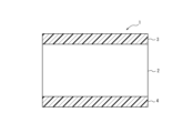
- FIG. 2 is a diagram showing a cross section of an example of a resin-coated metal plate.
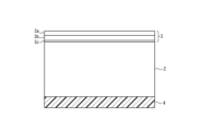
- FIG. 1 is a diagram showing a cross section of an example of a resin-coated metal sheet having a three-layer resin coating layer.
- the resin-coated metal sheet of the present invention is a resin-coated metal sheet having a resin coating layer on at least one side of a metal sheet, the resin coating layer containing 90% by mass or more of polyester resin based on the total resin, the amount of crystals in the resin coating layer being 15% or less, the arithmetic mean height Sa of the surface of the resin coating layer being 0.30 ⁇ m or less, the resin coating layer containing 8% by mass or more and 30% by mass or less of titanium dioxide, and the amount of Ti detected at the interface of the resin coating layer with the metal sheet as determined by elemental analysis using X-ray photoelectron spectroscopy is 2 atomic % or less.
- the present invention can suppress appearance defects (rough surface) that occur in the resin coating layer of a resin-coated metal sheet during heat treatment after can-making, and can also suppress a decrease in the smoothness of the surface of the resin coating layer during coating. This makes it possible to provide a resin-coated metal sheet with a smooth and beautiful appearance. Furthermore, it is possible to provide a resin-coated metal sheet that reduces residual stress after can-making and has excellent workability of the resin coating layer and adhesion after processing.
- FIG. 1 shows an example of a cross section of a resin-coated metal sheet 1 according to one embodiment.
- the resin-coated metal sheet 1 shown in FIG. 1 has a resin coating layer 3 on the front side of the metal sheet 2 and a resin coating layer 4 on the back side of the metal sheet 2.
- the resin coating layer may be provided on only one side of the metal sheet 2.
- the resin coating layer 3 provided on the front side of the metal sheet 2 and the resin coating layer 4 provided on the back side of the metal sheet 2 are located on the outer and inner sides of the two-piece can after can forming, respectively.
- At least one of the resin coating layers 3 and 4 is a resin coating layer containing titanium dioxide.
- metal sheet First, the metal sheet will be described.
- a steel sheet, an aluminum sheet, or the like that is widely used as a material for cans can be used.
- TFS tin free steel
- the TFS is not particularly limited by the adhesion amount of the metal chromium layer and the chromium oxide layer, but preferably has a metal chromium layer with an adhesion amount of 50 mg/ m2 or more and 200 g /m2 or less, and a chromium oxide layer with an adhesion amount of 3 mg/ m2 or more and 30 g/m2 or less on the surface thereof, calculated as metal chromium.
- the type of metal sheet is not particularly limited as long as it can be formed into a desired shape, but a steel sheet having the component composition and manufacturing method described below is preferred.
- DR Double Reduced
- IF Interstitial Free
- the mechanical properties of the metal plate are not particularly limited, so long as it can be formed into the desired shape.
- the Lankford value (r value) which is an index of plastic anisotropy, is preferably 0.8 or more.
- the absolute value of the in-plane anisotropy ⁇ r of the r value is 0.7 or less.
- the composition of the metal plate is not particularly limited, but may be, for example, a steel plate containing component elements such as Si, Mn, P, S, Al, and N.
- the Si content is preferably 0.001% by mass or more and preferably 0.1% by mass or less.
- the Mn content is preferably 0.01% by mass or more and preferably 0.6% by mass or less.
- the P content is preferably 0.002% by mass or more and preferably 0.05% by mass or less.
- the S content is preferably 0.002% by mass or more and preferably 0.05% by mass or less.
- the Al content is preferably 0.005% by mass or more and preferably 0.100% by mass or less.
- the N content is preferably 0.0005% by mass or more and preferably 0.020% by mass or less.
- the composition may further contain other components such as Ti, Nb, B, Cu, Ni, Cr, Mo, and V. From the viewpoint of ensuring corrosion resistance, etc., it is preferable that the total content of these component elements is 0.02 mass
- the thickness of the metal plate is not particularly limited, but can be, for example, 0.10 mm or more and 0.50 mm or less.
- the resin-coated metal sheet is provided with a resin coating layer mainly composed of polyester resin on at least one side of the metal sheet.
- the resin coating layer is made to have a polyester resin content of 90% by mass or more in terms of solid content.
- the polyester resin content of the resin minus the weight of the inorganic additives is made to be 90% by mass or more.
- Polyester resin is a polymer consisting of dicarboxylic acid units and glycol units.
- the dicarboxylic acid units that can be used include units derived from aromatic dicarboxylic acids such as terephthalic acid, isophthalic acid, naphthalenedicarboxylic acid, diphenyldicarboxylic acid, diphenylsulfonedicarboxylic acid, diphenoxyethanedicarboxylic acid, 5-sodium sulfoisophthalic acid, and phthalic acid; aliphatic dicarboxylic acids such as oxalic acid, succinic acid, adipic acid, sebacic acid, dimer acid, maleic acid, and fumaric acid; alicyclic dicarboxylic acids such as cyclohexanedicarboxylic acid; and oxycarboxylic acids such as p-oxybenzoic acid.
- aromatic dicarboxylic acids such as terephthalic acid, isophthalic acid, naphthalenedicarboxylic acid, diphenyldicarboxylic acid, diphen
- the polyester resin contains 90 mol % or more of terephthalic acid units among the dicarboxylic acid units. If the terephthalic acid units are 90 mol % or more of the dicarboxylic acid units contained in the polyester resin, sufficient heat resistance against frictional heat during continuous can forming processing can be ensured, and more stable moldability and coatability can be obtained.
- glycol units units derived from aliphatic glycols such as ethylene glycol, propanediol, butanediol, pentanediol, hexanediol, and neopentyl glycol; alicyclic glycols such as cyclohexanedimethanol; aromatic glycols such as bisphenol A and bisphenol S; and diethylene glycol, etc., can be used.
- aliphatic glycols such as ethylene glycol, propanediol, butanediol, pentanediol, hexanediol, and neopentyl glycol
- alicyclic glycols such as cyclohexanedimethanol
- aromatic glycols such as bisphenol A and bisphenol S
- the above dicarboxylic acids and glycols may be used in combination as long as the heat resistance and processability are not impaired.
- the titanium dioxide content is 8% by mass or more and 30% by mass or less. If the titanium dioxide content is less than 8% by mass, the underlying metal cannot be sufficiently concealed, and if it exceeds 30% by mass, the workability of the resin coating layer is impaired. In other words, if the titanium dioxide content is within the above-mentioned range, it is possible to conceal the underlying metal and increase the clarity of the print, obtain a good white appearance, and do not impair the workability of the resin coating layer.
- alumina, calcium carbonate, barium sulfate, etc. can be exemplified as white pigments, but titanium dioxide has strong coloring power and can ensure good appearance even after can formation.
- titanium dioxide of the rutile acid type with a purity of 90% by mass or more is preferable because it has better dispersibility when mixed with a resin material.
- the titanium dioxide content of the resin coating layer is preferably 10% by mass or more.
- the titanium dioxide content of the resin coating layer is preferably 22% by mass or less.
- the titanium dioxide content of the entire resin coating layer composed of multiple layers is set to 8% by mass or more and 30% by mass or less.
- the amount of crystals in the resin coating layer is 15% or less. By setting the amount of crystals to 15% or less, it is possible to obtain high moldability required for forming a two-piece can, and to suppress defects in appearance (rough skin) that occur in the resin coating layer during heat treatment after can-making. In addition, by setting the amount of crystals to a low value and reducing the residual stress in the resin coating layer after can-making, it is possible to obtain excellent adhesion even after processing.
- the amount of crystals in the resin coating layer is preferably 12% or less, more preferably 10% or less.
- the amount of crystals in the resin material minus the mass of the inorganic additive must be 15% or less.
- the lower limit of the amount of crystals is not particularly limited, but the amount of crystals may be 1% or more.
- the amount of crystals is calculated based on the content of the inorganic additive obtained by thermogravimetry, and the heat of crystallization and the heat of fusion obtained by differential scanning calorimetry, as shown below.
- the inorganic additive refers to an inorganic additive among inorganic pigments and additives other than inorganic pigments.
- the amount of crystallinity is measured as follows. In the same manner as in the measurement of the inorganic additive content, the metal plate is dissolved from the resin-coated metal plate to isolate the resin coating layer, and then dried. The resin coating layer after drying is measured from 0°C to 300°C at a heating rate of 10°C/min using a differential scanning calorimeter (DSCQ100) manufactured by TA Instruments. The amount of crystallinity is calculated from the area of the exothermic peak observed between 100 and 200°C, and the amount of heat of fusion is calculated from the area of the endothermic peak measured between 200°C and 280°C. The amount of crystallinity is calculated from the obtained amount of crystallization and amount of heat of fusion according to the following formula (2).
- the content of the inorganic additive is determined by the above-mentioned method.
- Amount of crystallization [%] (amount of heat of fusion [J/g] - amount of heat of crystallization [J/g]) x 100 / (100 - content of inorganic additive [%]) / 140.2 [J/g] x 100 ...
- the arithmetic mean height Sa of the resin coating layer surface is 0.30 ⁇ m or less. If the arithmetic mean height Sa of the resin coating layer surface exceeds 0.30 ⁇ m, the roughness of the resin coating layer surface is large, so that a colored resin coating layer has a mottled pattern, and a colorless resin coating layer has a cloudy appearance.
- the lower limit of the arithmetic mean height Sa of the resin coating layer surface is not particularly limited, but the arithmetic mean height Sa is preferably 0.10 ⁇ m or more.
- the arithmetic mean height Sa of the resin coating layer surface is measured by surface roughness analysis using a 3D shape measuring instrument.
- shape measurements are taken over a field of view of 1.9 mm x 1.4 mm at 160x magnification, and the arithmetic mean height Sa is calculated by surface roughness analysis. Measurements are taken at five randomly selected locations on the same surface of the resin-coated metal plate, and the maximum value is taken as the arithmetic mean height Sa of the resin-coated metal plate.
- the arithmetic mean height Sa is used as an index of surface smoothness because it is highly correlated with the appearance of the product.
- arithmetic mean height examples include Ra, which is the arithmetic mean height of lines, and Sa, which is the arithmetic mean height of surfaces.
- the amount of crystals and surface smoothness of the resin coating layer can be achieved, for example, by a two-step process described in the manufacturing method described below, in which the resin coating layer is coated with a metal plate at a low temperature, and then heat-treated for a very short period of time at a temperature above the melting point.
- the amount of Ti detected at the interface between the resin coating layer and the metal plate, which is elementally analyzed by X-ray photoelectron spectroscopy is 2 atomic % or less.
- the amount of Ti detected at the interface between the resin coating layer and the metal plate exceeds 2 atomic %, titanium dioxide present at the interface between the resin coating layer and the metal plate inhibits adhesion between the metal plate and the resin coating layer, and the adhesion of the resin coating layer after can manufacturing is insufficient.
- the amount of Ti detected at the interface between the resin coating layer and the metal plate, which is elementally analyzed by X-ray photoelectron spectroscopy is 1 atomic % or less.
- the lower limit of the amount of Ti detected at the interface between the resin coating layer and the metal plate, which is elementally analyzed by X-ray photoelectron spectroscopy is not particularly limited, and may be 0 atomic %.
- the amount of Ti detected at the interface between the resin coating layer and the metal plate, which is elementally analyzed by X-ray photoelectron spectroscopy can be measured by a conventionally known method, as described in the examples described later. It is preferable that the measurement is performed at randomly selected multiple points on the same surface of the resin-coated metal plate, and the average value of the measurement results is taken as the amount of Ti detected.
- the number of randomly selected locations is preferably five or more, taking into consideration variations within the surface.
- FIG. 2 shows a resin-coated metal plate having a multi-layer structure in which a first layer 3c, a second layer 3b, and a third layer 3a are laminated in this order on a metal plate 2.
- the third layer 3a is an optional layer.
- the thickness of the first layer 3c is preferably 2 ⁇ m or more in order to ensure sufficient adhesion with the metal plate, and is preferably 5 ⁇ m or less in order to ensure a good appearance of the film.
- the titanium dioxide content of the first layer 3c is preferably 2 mass% or less.
- the amount of Ti detected on the surface of the resin coating layer as analyzed by X-ray photoelectron spectroscopy is 2 atomic % or less. If the amount of Ti detected is 2 atomic % or less, scraping of the resin coating layer can be suppressed even in more severe can manufacturing processes. More preferably, the amount of Ti detected on the surface of the resin coating layer as analyzed by X-ray photoelectron spectroscopy is 1 atomic % or less. There is no particular limit to the lower limit of the amount of Ti detected on the surface of the resin coating layer as analyzed by X-ray photoelectron spectroscopy, and it may be 0 atomic %.
- the amount of Ti detected on the resin coating layer surface analyzed by X-ray photoelectron spectroscopy is measured by the following method.
- the isolated resin coating layer is then thoroughly washed with distilled water and vacuum dried.
- X-ray photoelectron spectroscopy is performed on the interface side of the dried resin coating layer with the metal plate using an X-ray photoelectron spectroscopy analyzer (SSX-100 manufactured by SSI).
- the X-ray source is monochromated K ⁇ rays of Al, and the measurement is performed under the conditions of a measurement area of 600 ⁇ m ⁇ , six accumulations, and a photoelectron escape angle of 35°.
- the elements are quantified from the wide scan spectrum obtained by the measurement, and the element ratio of Ti among the detected elements is calculated. Measurements are performed at five randomly selected points for each sample, and the average value is taken as the amount of Ti detected on the resin coating layer surface analyzed by X-ray photoelectron spectroscopy. The measurement positions are spaced at least 5 mm apart from each other.
- the Ti element ratio on the surface of the resin-coated metal plate is also obtained by measuring the surface of the resin-coated metal plate under similar conditions.
- the surface of the resin coating layer has a layer that does not contain titanium dioxide or has a very low titanium dioxide content.
- the titanium dioxide content of the third layer 3a shown in Figure 2 can be reduced.
- the layer thickness of the third layer 3a is preferably 2 ⁇ m or more, and preferably 5 ⁇ m or less.
- the titanium dioxide content of the third layer 3a is preferably 2 mass% or less.
- the resin coating layer In order to reduce the amount of titanium dioxide on the surface of the resin coating layer in addition to the interface between the resin coating layer and the metal plate described above, it is preferable to have at least a three-layer structure in which the resin coating layer has layers with a low titanium dioxide content on both sides (the third layer 3a and the first layer 3c in Figure 2).
- 0.010% by mass or more of wax may be added to the resin coating layer on at least one side, or 1.0% by mass or less of wax may be added.
- the amount of wax added is 1.0% by mass or less, it is easier to form the resin coating layer, so the amount of wax added is preferably 1.0% by mass or less.
- the resin coating layer has a multi-layer structure as described above, only the wax added near the surface of the resin coating layer contributes to the sliding properties of the resin coating layer surface, so wax may be added only to the layer located on the surface.
- wax may also be added to the layer on the metal plate side of the resin coating layer, for example, by using the same material for both layers of the resin coating layer.
- the wax at least one selected from the group consisting of polyolefin waxes such as polyethylene and polypropylene and modified products thereof; natural waxes such as carnauba wax; polyamide waxes; and polyester waxes, or mixtures thereof, can be used.
- Additional additives such as antioxidants, heat stabilizers, lubricants, crystal nucleating agents, ultraviolet absorbers, and antistatic agents may be added to the resin coating layer as necessary, provided that the effects of the present invention are not impaired.
- Coloring pigments other than white pigments may also be added to the resin coating layer to improve the appearance of the inner and outer surfaces of the metal container.
- the thickness of the resin coating layer is not particularly limited, but may be, for example, 6 mm or more and 50 mm or less.
- two-piece cans with a smooth and beautiful appearance can be manufactured.
- the two-piece cans can be manufactured by conventional methods.
- the resin coating layer is located on the outer surface side of the two-piece can.
- the method for producing a resin-coated metal sheet according to the present invention comprises preparing a thermoplastic resin film having a thickness of 2 ⁇ m or more, a multilayer structure including a first layer containing 2 mass% or less of titanium dioxide, and a second layer in contact with the first layer, the thermoplastic resin film containing 8 mass% or more to 30 mass% or less of titanium dioxide as a whole, and containing 90 mass% or more of polyester resin based on the total resin,
- the thermoplastic resin film is pressed against at least one surface of a metal plate heated to a temperature between (the melting point of the thermoplastic resin film - 40 ° C) and (the melting point of the thermoplastic resin film + 5 ° C), with the first layer being brought into contact with the metal plate;
- the method is characterized in that the metal plate is heated to a heat treatment temperature of (the melting point of the thermoplastic resin film + 5°C) or more (the melting point of the thermoplastic resin film +
- thermoplastic resin film that will become the resin coating layer is first produced.
- the thermoplastic resin film contains a thermoplastic resin and titanium dioxide.
- the thermoplastic resin that can be used is a resin that contains 90 mass% or more of polyester resin relative to the total resin. Additives, etc. are also as described above in the explanation of the resin coating layer.
- the amount of titanium dioxide added during production is the titanium dioxide content in the resin coating layer.
- the thermoplastic resin film includes a first layer having a thickness of 2 ⁇ m or more and containing 2 mass% or less of titanium dioxide, and a second layer in contact with the first layer. Furthermore, the thermoplastic resin film contains 8 mass% or more and 30 mass% or less of titanium dioxide as a whole, and contains 90 mass% or more of polyester resin based on the total resin. In addition, the thermoplastic resin film preferably has a three-layer structure having a third layer in contact with the second layer. The third layer preferably has a thickness of 2 ⁇ m or more and contains 2 mass% or less of titanium dioxide.
- the thickness of the entire resin coating layer and each resin layer is measured using the method described below.
- the resin-coated metal plate is cut into a size of approximately 20 mm x 15 mm, embedded in embedding resin, and cross-section polished.
- the surface of the resin-coated metal plate to be observed is then cross-section polished using a cross-section polisher (CP).
- CP cross-section polisher
- a cross-sectional photograph of each resin layer of the resin-coated metal plate is taken at a magnification of 1000 to 3000 times using an FE-SEM.
- the thickness of the entire resin coating layer and each resin layer is obtained by measuring the cross-sectional photograph obtained.
- thermoplastic resin film is not particularly limited, but in one example, it can be produced as follows. First, the thermoplastic resin raw materials and titanium dioxide that make up each layer are heated and dried under vacuum as necessary, and then fed into independent extruders, where the thermoplastic resin is heated and melted. The heated and melted thermoplastic resin is poured into different flow paths through a filter or the like. Foreign matter and denatured resin can be removed by the filter. Each thermoplastic resin is fed into a lamination device through a different flow path. A feed block and a multi-manifold die can be used as the lamination device.
- each thermoplastic resin is formed into a sheet shape using a T-die, discharged, and extruded onto a cooling body such as a cast drum.
- the extruded sheet is cooled and solidified to obtain an unstretched thermoplastic resin film having a multi-layer structure.
- the thermoplastic resin film forming the resin coating layer is preferably obtained by stretching the above-mentioned unstretched film to form a stretched film, from the viewpoint of reducing the surface roughness of the resin coating layer.
- the method of obtaining a stretched film is not particularly limited, but it is possible to use a method of obtaining a uniaxially stretched film by stretching in the lengthwise or widthwise direction of a film forming machine; a method of obtaining a sequentially biaxially stretched film by stretching in the lengthwise or widthwise direction and then stretching in the other direction; and a method of obtaining a simultaneous biaxially stretched film by simultaneously stretching in the lengthwise and widthwise directions.
- thermoplastic resin film is heated to above its melting point and pressed onto a metal plate using a laminating roll (thermocompression film lamination method).
- This thermocompression film lamination method is advantageous in that it keeps manufacturing costs down and allows for energy-saving production.
- the first layer of the thermoplastic resin film is pressed into contact with the metal plate.
- a resin-coated metal plate is manufactured by carrying out a two-stage process in which the metal plate is coated with a thermoplastic resin film at a low temperature, and then heat-treated for a very short time at a temperature above the melting point.
- thermocompression bonding time When bonding a thermoplastic resin film to a metal plate, it is necessary to control the bonding conditions and ensure a smooth surface.
- the time during which the resin film is bonded to the metal plate by the laminating roll is preferably 10 msec or more, and more preferably 40 msec or less.
- thermocompression bonding time is 40 msec or less, softening of the laminating roll side of the thermoplastic resin film can be more appropriately prevented, and the smoothness of the resin coating layer surface can be more appropriately improved.
- the thermocompression bonding time is more preferably 15 msec or more.
- the thermocompression bonding time is more preferably 30 msec or less.
- the temperature of the metal plate during compression should be at least (melting point of thermoplastic resin film - 40°C) and not more than (melting point of thermoplastic resin film + 5°C). If the temperature of the metal plate during compression is less than (melting point of thermoplastic resin film - 40°C), the metal plate side of the thermoplastic resin film may not melt sufficiently, and the adhesion between the metal plate and the resin coating layer may decrease.
- the temperature of the metal plate during compression exceeds (melting point of thermoplastic resin film + 5°C)
- the surface of the thermoplastic resin film on the laminating roll side will soften and the smoothness of the resin coating layer surface will be impaired, which is not preferable.
- the temperature of the metal plate is based on the surface temperature of the metal plate.
- the temperature of the laminating roll during lamination is not particularly limited, but it is preferable to set it to 60°C or higher to ensure the impact resistance of the film after lamination. Also, it is preferable to set it to 150°C or lower to prevent the film from welding to the laminating roll during lamination.
- the resin-coated metal plate is cooled.
- a cooling method water cooling using temperature-adjusted water or gas cooling using air, nitrogen, etc. is preferable. From the viewpoint of simplifying the equipment, water cooling is more preferable.
- the water cooling method include a method of immersing the resin-coated metal plate in a water tank containing water, and a method of spraying water onto the resin-coated metal plate from a nozzle, etc.
- the cooling stop temperature is preferably 5°C or higher. By setting the cooling stop temperature to 5°C or higher, condensation on the resin-coated metal plate and surrounding equipment after cooling can be more effectively prevented.
- the cooling stop temperature is preferably (glass transition temperature of the thermoplastic resin film - 10°C) or lower. If the cooling stop temperature is (glass transition temperature of the thermoplastic resin film - 10°C) or lower, the fluidity of the amorphous structure inside the resin coating layer can be more effectively suppressed, and the resin-coated metal plate can be more effectively prevented from coming into contact with a roll, etc. after cooling, resulting in roughness on the surface.
- the resin-coated metal sheet laminated at low temperatures as described above has a smooth surface, it has a high degree of crystallinity and is unable to suppress appearance defects (rough skin) that occur in the resin coating layer during heat treatment after can manufacturing.
- appearance defects rough skin
- the preferred method of heat treatment is to pass the sheet through a heating furnace that uses infrared rays (IR) or induction heating (IH), which can heat the sheet without contact and in a short time.
- IR infrared rays
- IH induction heating
- the resin-coated metal sheet does not come into contact with various rolls, etc., from the start of heat treatment to the end of cooling.
- the heat treatment temperature should be at least (melting point of thermoplastic resin film + 5°C) and at most (melting point of thermoplastic resin film + 30°C). If the heat treatment temperature is less than (melting point of thermoplastic resin film + 5°C), the resin coating layer may not melt sufficiently, and the desired crystallization of the resin coating layer may not be achieved. On the other hand, if the heat treatment temperature exceeds (melting point of thermoplastic resin film + 30)°C, it is not preferable because the resin coating layer may deteriorate due to heat.
- the heat treatment temperature is based on the temperature of the metal plate.
- the resin coating layers on both sides satisfy the above heat treatment temperature conditions. Therefore, it is preferable that the difference in melting points of the resin coating layers on both sides is 25°C or less. If the difference in melting points of the resin coating layers on both sides is 25°C or less, it is easy to set the heat treatment temperature of both sides to the above-mentioned range of (melting point of thermoplastic resin film + 5°C) or more and (melting point of thermoplastic resin film + 30°C) or less.
- the temperature is raised to the above heat treatment temperature in 0.5 to 1.5 seconds. If the temperature is raised in less than 0.5 seconds, it is difficult to control the temperature, and temperature differences in the width direction may occur, resulting in variations in the physical properties of the resin coating layer.
- the heat treatment temperature is maintained for 0.5 to 1.5 seconds. If the heat treatment temperature is maintained for less than 0.5 seconds, the thermoplastic resin film may not melt sufficiently, and the desired degree of crystallization of the resin coating layer may not be achieved.
- the heating time or the time held at the heat treatment temperature exceeds 1.5 seconds, it will be necessary to transport the plate over a very long distance without contacting rolls, etc., which will require huge equipment and may cause problems such as plate vibration. Therefore, it is preferable that the heating time and the time held at the heat treatment temperature are each 1.5 seconds or less, and that the total time is also 3.0 seconds or less.
- the resin-coated metal sheet is cooled.
- a cooling method water cooling using temperature-adjusted water or gas cooling using air, nitrogen, etc. is preferable. From the viewpoint of simplifying the equipment, water cooling is more preferable.
- the water cooling method include a method of immersing the resin-coated metal sheet in a water tank and a method of spraying water onto the resin-coated metal sheet from a nozzle, etc.
- the cooling stop temperature is preferably 5°C or higher. By setting the cooling stop temperature to 5°C or higher, condensation on the resin-coated metal sheet and surrounding equipment after cooling can be more effectively prevented.
- the cooling stop temperature is preferably (glass transition temperature of the thermoplastic resin film - 10°C) or lower.
- the cooling stop temperature is (glass transition temperature of the thermoplastic resin film - 10°C) or lower, the fluidity of the amorphous structure inside the resin coating layer can be more effectively suppressed, and the resin-coated metal sheet can be more effectively prevented from coming into contact with a roll, etc. after cooling, resulting in roughness on the surface.
- the manufacturing conditions other than those mentioned above can be determined by conventional methods.
- a chrome-plated steel plate (TFS) with a thickness of 0.22 mm, a metal chrome deposition amount of 120 mg/m 2 , a chrome oxide deposition amount of 10 mg/m 2 (metal chrome equivalent), and a tempering degree of T3CA was used.
- TFS chrome-plated steel plate
- a metal chrome deposition amount of 120 mg/m 2 a chrome oxide deposition amount of 10 mg/m 2 (metal chrome equivalent)
- a tempering degree of T3CA was used as the metal plate.
- a resin having the composition shown in Table 1 a rutile acid type titanium dioxide having a purity of 90 mass%, and a wax were prepared.
- the resin, titanium dioxide, and wax were put into an extruder and heated and melted.
- the melted raw material was sent to a lamination device (feed block) through a filter, formed into a sheet shape with a T-die, and cooled and solidified on a cast drum to produce a thermoplastic resin film.
- the thermoplastic resin film was stretched in the longitudinal direction and then in the transverse direction to obtain a sequentially biaxially stretched film.
- thermocompression film lamination method in each example, a resin film was coated on a metal plate using the thermocompression film lamination method under the conditions shown in Table 2, and then water-cooled.
- the thermocompression time was 20 msec., and the first layer of the thermoplastic resin film was brought into contact with the metal plate and pressed (in No. 24, a titanium dioxide-added layer was pressed).
- a heat treatment was performed under the conditions shown in Table 2, followed by water cooling to produce a resin-coated metal plate. Note that no heat treatment was performed for Nos. 26 and 27.
- the thickness of the resin coating layer, inorganic additive content, crystal amount, surface roughness, Ti element ratio at the interface between the resin coating layer and the metal plate, and at the surface of the resin coating layer were measured for the obtained resin-coated metal sheets using the methods described above.
- the melting point of the resin coating layer was also measured using the method described below. The measurement results are shown in Table 1. Note that in each example, the resin constituting the resin coating layer was polyester resin, with the proportion of polyester resin being 100% by mass in solid content terms relative to the total resin, and the composition of the polyester resin in each example is shown in Table 1.
- the resin-coated metal plate was immersed in a 1:1 mixed solution of concentrated hydrochloric acid (12 mol/L):distilled water at room temperature, and the metal plate was dissolved to isolate the resin coating layer. The isolated resin coating layer was then thoroughly washed with distilled water and vacuum dried. The dried resin coating layer was measured from 0°C to 300°C at a heating rate of 10°C/min using a differential scanning calorimeter (DSCQ100) manufactured by TA Instruments, and the peak temperature of the endothermic peak measured between 200°C and 280°C was taken as the melting point of the resin coating layer.
- DSCQ100 differential scanning calorimeter
- a part of the resin coating layer was peeled off from the end of the cut-out sample on the can body opening side, and the peeled resin coating layer was opened in the opposite direction (angle 180 degrees) to the metal plate from which the resin coating layer was peeled off, and a peel test was performed at a tensile speed of 30 mm/min.
- the adhesion per 15 mm width was evaluated according to the following criteria.
- the surface to be evaluated for adhesion was the outer surface side of the can. Evaluation " ⁇ ": 3.0N/15mm or more Evaluation " ⁇ ”: 2.0N/15mm or more, less than 3.0N/15mm Evaluation " ⁇ ”: 1.0N/15mm or more, less than 2.0N/15mm Evaluation " ⁇ ": less than 1.0N/15mm
- the present invention can suppress appearance defects (rough surface) that occur in the resin coating layer of a resin-coated metal sheet during heat treatment after can manufacturing, and can also suppress a decrease in the smoothness of the surface of the resin coating layer during coating. This makes it possible to provide a resin-coated metal sheet that has a smooth and beautiful appearance, excellent workability, and excellent adhesion of the resin coating layer after processing.
Landscapes
- Engineering & Computer Science (AREA)
- Mechanical Engineering (AREA)
- Physics & Mathematics (AREA)
- Fluid Mechanics (AREA)
- Thermal Sciences (AREA)
- Laminated Bodies (AREA)
Abstract
Description
前記樹脂被覆層の結晶量が15%以下であり、
前記樹脂被覆層の表面の算術平均高さSaが0.30μm以下であり、
前記樹脂被覆層が8質量%以上30質量%以下の二酸化チタンを含有し、
X線光電子分光測定により元素分析した前記樹脂被覆層の前記金属板との界面におけるTi検出量が2原子%以下である、樹脂被覆金属板。
前記第一層が、2μm以上の厚みを有し、かつ、2質量%以下の二酸化チタンを含有する、[1]又は[2]に記載の樹脂被覆金属板。
前記第三層が、2μm以上の厚みを有し、かつ、2質量%以下の二酸化チタンを含有する、[3]に記載の樹脂被覆金属板。
前記熱可塑性樹脂フィルムを、(前記熱可塑性樹脂フィルムの融点-40℃)以上(前記熱可塑性樹脂フィルムの融点+5℃)以下に加熱した金属板の少なくとも片面に、前記第一層を前記金属板に接触させて圧着し、
前記金属板を0.5秒以上1.5秒以下で(前記熱可塑性樹脂フィルムの融点+5℃)以上(前記熱可塑性樹脂フィルムの融点+30℃)以下の熱処理温度まで昇温して、前記熱処理温度で0.5秒以上1.5秒以下保持した後に冷却して、樹脂被覆金属板を得る、樹脂被覆金属板の製造方法。
はじめに、金属板について説明する。樹脂被覆金属板の金属板としては、缶用材料に広く用いられている鋼板及びアルミニウム板等を用いることができる。
(1)C(カーボン)量が0.003質量%超0.10質量%以下の低炭素鋼を用い、連続焼鈍で再結晶焼鈍して得た鋼板。
(2)C量が0.003質量%超0.10質量%以下の低炭素鋼を用い、連続焼鈍で再結晶焼鈍及び過時効処理して得た鋼板。
(3)C量が0.003質量%超0.10質量%以下の低炭素鋼を用い、箱焼鈍で再結晶焼鈍して得た鋼板。
(4)C量が0.003質量%超0.10質量%以下の低炭素鋼を用い、連続焼鈍又は箱焼鈍で再結晶焼鈍した後に、二次冷間圧延(DR(Double Reduced)圧延)して得た鋼板。
(5)C量が0.003質量%以下の極低炭素鋼にNb、Ti等の固溶したCを固定する元素を添加したIF(Interstitial Free)鋼を用い、連続焼鈍で再結晶焼鈍して得た鋼板。
樹脂被覆金属板は、上記の金属板の少なくとも片面に、ポリエステル樹脂を主成分とする樹脂被覆層を備える。樹脂被覆層は、構成する樹脂中のポリエステル樹脂の割合が固形分換算で90質量%以上であるものとする。樹脂被覆層中に無機添加材(無機顔料など)が含まれる場合は、それら無機添加材の重量を差し引いた樹脂中のポリエステル樹脂の割合が90質量%以上であるものとする。
樹脂被覆層の結晶量は15%以下とする。結晶量を15%以下とすることで、2ピース缶の成形に必要な高い成形性を得ることができ、製缶加工後の熱処理時に樹脂被覆層に生じる外観上の欠陥(肌荒れ)を抑制することができる。また、結晶量を低い値とし、製缶加工後の樹脂被覆層中の残留応力を低減することで、加工後においても優れた密着性を得ることができる。樹脂被覆層の結晶量は、好ましくは12%以下、より好ましくは10%以下である。樹脂被覆層に無機添加材(無機顔料など)が含まれる場合は、無機添加材の質量を差し引いた樹脂材料中における結晶量が15%以下である必要がある。結晶量の下限は特に限定されないが、結晶量は1%以上であり得る。なお、結晶量は、以下に示すとおり、熱重量測定により得られた無機添加材含有量、並びに、示差走査熱量測定により得られた結晶化熱量及び融解熱量に基づいて算出する。ここで無機添加材とは、無機顔料及び無機顔料以外の添加材のうち無機系の添加材を指す。
無機添加材の含有量[%]=800℃における重量[mg]/室温における重量[mg]×100…(1)
結晶量[%]=(融解熱量[J/g]-結晶化熱量[J/g])×100/(100-無機添加材含有量[%])/140.2[J/g]×100…(2)
樹脂被覆層表面の算術平均高さSaは0.30μm以下とする。樹脂被覆層表面の算術平均高さSaが0.30μmを超える場合、樹脂被覆層表面の粗さが大きいため、有色の樹脂被覆層の場合はまだら模様に、無色の樹脂被覆層の場合は曇った外観となる。樹脂被覆層表面の算術平均高さSaの下限は特に限定されないが、当該算術平均高さSaは0.10μm以上とすることが好ましい。
X線光電子分光測定により元素分析した樹脂被覆層と金属板との界面におけるTi検出量は、2原子%以下とする。樹脂被覆層と金属板との界面におけるTi検出量が2原子%を超える場合、樹脂被覆層と金属板との界面に存在する二酸化チタンが金属板と樹脂被覆層との密着を阻害し、製缶加工後の樹脂被覆層の密着性が不足する。好ましくは、X線光電子分光測定により元素分析した樹脂被覆層と金属板との界面におけるTi検出量は1原子%以下である。X線光電子分光測定により元素分析した樹脂被覆層と金属板との界面におけるTi検出量の下限は特に限定されず、0原子%であってもよい。X線光電子分光測定により元素分析した樹脂被覆層と金属板との界面におけるTi検出量は、後述の実施例に記載のように、従来公知の方法で測定できる。測定は、樹脂被覆金属板の同一面内の無作為に選んだ複数箇所で行い、測定結果の平均値をTi検出量とするのが好ましい。無作為に選ぶ複数箇所の数は、面内のばらつきを考慮して5か所以上であることが好ましい。
本発明に係る樹脂被覆金属板の製造方法は、2μm以上の厚みを有し、かつ、2質量%以下の二酸化チタンを含有する第一層と、前記第一層に接する第二層と、を含む複層構造を有し、全体として8質量%以上30質量%以下の二酸化チタンを含有し、ポリエステル樹脂を全樹脂に対して90質量%以上含有する熱可塑性樹脂フィルムを用意し、
前記熱可塑性樹脂フィルムを、(前記熱可塑性樹脂フィルムの融点-40℃)以上(前記熱可塑性樹脂フィルムの融点+5℃)以下に加熱した金属板の少なくとも片面に、前記第一層を前記金属板に接触させて圧着し、
前記金属板を0.5秒以上1.5秒以下で(前記熱可塑性樹脂フィルムの融点+5℃)以上(前記熱可塑性樹脂フィルムの融点+30℃)以下の熱処理温度まで昇温して、前記熱処理温度で0.5秒以上1.5秒以下保持した後に冷却して、樹脂被覆金属板を得ることを特徴とする。
室温で濃塩酸(12mоl/L):蒸留水=1:1混合溶液中に樹脂被覆金属板を浸漬し、金属板を溶解して樹脂被覆層を単離した。その後、単離した樹脂被覆層を蒸留水で十分に洗浄した後に真空乾燥した。乾燥後の樹脂被覆層について、TAインスツルメンツ社製の示差走査熱量測定装置(DSCQ100)を用いて、10℃/分の昇温速度で0℃から300℃まで測定し、200℃~280℃の間で測定された吸熱ピークのピーク温度を、樹脂被覆層の融点とした。

各例の樹脂被覆金属板にパラフィンワックスを塗布した後、直径180mmの円板ブランクを打抜いた。この円板ブランクにカッピングプレス機での絞り成形、次いで2段の再絞り成形及び1段のしごき成形による加工を施し、内径52mm、缶高さ163mmの缶を成形した。成形後の缶について、缶体外面側の樹脂被覆層表面を目視で観察し、以下の基準に従って加工性を評価した。
評価「◎」:削れが観察されない。
評価「○」:缶フランジ部から5mm以内の高さで削れが発生。実用上の問題なし。
評価「×」:缶フランジ部から5mmを超えた高さで削れが発生。実用上の問題あり。
各例の樹脂被覆金属板にパラフィンワックスを塗布した後、直径180mmの円板ブランクを打抜いた。この円板ブランクにカッピングプレス機での絞り成形、次いで2段の再絞り成形及び1段のしごき成形による加工を施し、内径52mm、缶高さ163mmの缶を成形した。成形後の缶を、2分間で缶体温度が(樹脂被覆層の融点+5)℃となる条件で熱風炉を用いて加熱した後に、冷風で急冷した。冷却後の缶体外面側の樹脂被覆層の状態を目視確認し、以下の基準に従って肌荒れを評価した。
評価「◎」:黒点、しわ等の外観上の欠陥が観察されない。
評価「○」:黒点、しわ等の外観上の欠陥が、缶フランジ部より5mm以内の高さ位置に発生。実用上の問題なし。
評価「△」:黒点、しわ等の外観上の欠陥が、缶フランジ部から5mmを超えて20mm以内の高さ位置に発生。実用上の問題あり。
評価「×」:黒点、しわ等の外観上の欠陥が、缶フランジ部から20mmを超えた高さ位置に発生。実用上の問題あり。
各例の樹脂被覆金属板の両面の、表面平滑性における外観の均一性について目視確認し、以下の基準に従い外観を評価した。
評価「〇」:外観上の異常なし。
評価「×」:まだら模様又は曇った外観など、外観上の異常あり。
各例の樹脂被覆金属板にパラフィンワックスを塗布した後、直径180mmの円板ブランクを打抜いた。この円板ブランクにカッピングプレス機での絞り成形、次いで2段の再絞り成形及び1段のしごき成形による加工を施し、内径52mm、高さ163mmの缶を成形した。成形後の缶の胴部より、缶高さ方向が長手方向(試験方向)となるようにピール試験用のサンプル(幅15mm×長さ120mm)を切り出した。切り出したサンプルの缶体開口部側の端部から樹脂被覆層を一部剥離し、剥離した樹脂被覆層を樹脂被覆層が剥離された金属板とは反対方向(角度180度)に開き、引張速度30mm/min.でピール試験を行った。以下に示す基準に従って幅15mm当たりの密着性を評価した。密着性評価の対象面は缶の外面側とした。
評価「◎」:3.0N/15mm以上
評価「○」:2.0N/15mm以上、3.0N/15mm未満
評価「△」:1.0N/15mm以上、2.0N/15mm未満
評価「×」:1.0N/15mm未満

2 金属板
3 樹脂被覆層
3a 第三層
3b 第二層
3c 第一層
4 樹脂被覆層
Claims (8)
- 金属板の少なくとも片面に、ポリエステル樹脂を全樹脂に対して90質量%以上含有する樹脂被覆層を備える樹脂被覆金属板であって、
前記樹脂被覆層の結晶量が15%以下であり、
前記樹脂被覆層の表面の算術平均高さSaが0.30μm以下であり、
前記樹脂被覆層が8質量%以上30質量%以下の二酸化チタンを含有し、
X線光電子分光測定により元素分析した前記樹脂被覆層の前記金属板との界面におけるTi検出量が2原子%以下である、樹脂被覆金属板。 - X線光電子分光測定により元素分析した前記樹脂被覆層の表面におけるTi検出量が2原子%以下である、請求項1に記載の樹脂被覆金属板。
- 前記樹脂被覆層が、前記金属板と接する第一層と、前記第一層上に位置する第二層と、を含む複層構造を有し、
前記第一層が、2μm以上の厚みを有し、かつ、2質量%以下の二酸化チタンを含有する、請求項1又は2に記載の樹脂被覆金属板。 - 前記樹脂被覆層が、前記第二層上に位置し、前記樹脂被覆層の表面を形成する第三層をさらに含む複層構造を有し、
前記第三層が、2μm以上の厚みを有し、かつ、2質量%以下の二酸化チタンを含有する、請求項3に記載の樹脂被覆金属板。 - 前記樹脂被覆層が0.010質量%以上1.0質量%以下のワックスを含有する、請求項1から4のいずれか一項に記載の樹脂被覆金属板。
- 請求項1から5のいずれか一項に記載の樹脂被覆金属板を用いてなり、前記樹脂被覆層が外面側に位置する、2ピース缶。
- 2μm以上の厚みを有し、かつ、2質量%以下の二酸化チタンを含有する第一層と、前記第一層に接する第二層と、を含む複層構造を有し、全体として8質量%以上30質量%以下の二酸化チタンを含有し、ポリエステル樹脂を全樹脂に対して90質量%以上含有する熱可塑性樹脂フィルムを用意し、
前記熱可塑性樹脂フィルムを、(前記熱可塑性樹脂フィルムの融点-40℃)以上(前記熱可塑性樹脂フィルムの融点+5℃)以下に加熱した金属板の少なくとも片面に、前記第一層を前記金属板に接触させて圧着し、
前記金属板を0.5秒以上1.5秒以下で(前記熱可塑性樹脂フィルムの融点+5℃)以上(前記熱可塑性樹脂フィルムの融点+30℃)以下の熱処理温度まで昇温して、前記熱処理温度で0.5秒以上1.5秒以下保持した後に冷却して、樹脂被覆金属板を得る、樹脂被覆金属板の製造方法。 - 前記熱可塑性樹脂フィルムが、前記第二層に接する第三層を有し、第三層が、2μm以上の厚みを有し、かつ、2質量%以下の二酸化チタンを含有する、請求項7に記載の樹脂被覆金属板の製造方法。
Priority Applications (4)
| Application Number | Priority Date | Filing Date | Title |
|---|---|---|---|
| JP2024521875A JP7750403B2 (ja) | 2023-01-23 | 2023-11-13 | 樹脂被覆金属板、2ピース缶、及び樹脂被覆金属板の製造方法 |
| CN202380089979.1A CN120457029A (zh) | 2023-01-23 | 2023-11-13 | 树脂覆盖金属板、两片罐及树脂覆盖金属板的制造方法 |
| EP23918531.7A EP4613478A4 (en) | 2023-01-23 | 2023-11-13 | Resin-coated metal sheet, two-part box, and method for producing a resin-coated metal sheet |
| KR1020257021436A KR20250116083A (ko) | 2023-01-23 | 2023-11-13 | 수지 피복 금속판, 2 피스 캔, 및 수지 피복 금속판의 제조 방법 |
Applications Claiming Priority (2)
| Application Number | Priority Date | Filing Date | Title |
|---|---|---|---|
| JP2023-008363 | 2023-01-23 | ||
| JP2023008363 | 2023-01-23 |
Publications (1)
| Publication Number | Publication Date |
|---|---|
| WO2024157576A1 true WO2024157576A1 (ja) | 2024-08-02 |
Family
ID=91970305
Family Applications (1)
| Application Number | Title | Priority Date | Filing Date |
|---|---|---|---|
| PCT/JP2023/040820 Ceased WO2024157576A1 (ja) | 2023-01-23 | 2023-11-13 | 樹脂被覆金属板、2ピース缶、及び樹脂被覆金属板の製造方法 |
Country Status (6)
| Country | Link |
|---|---|
| EP (1) | EP4613478A4 (ja) |
| JP (1) | JP7750403B2 (ja) |
| KR (1) | KR20250116083A (ja) |
| CN (1) | CN120457029A (ja) |
| TW (1) | TWI880490B (ja) |
| WO (1) | WO2024157576A1 (ja) |
Cited By (1)
| Publication number | Priority date | Publication date | Assignee | Title |
|---|---|---|---|---|
| WO2026009578A1 (ja) * | 2024-07-04 | 2026-01-08 | Jfeスチール株式会社 | 容器用金属板、容器用金属板の製造方法及び、缶の製造方法 |
Citations (9)
| Publication number | Priority date | Publication date | Assignee | Title |
|---|---|---|---|---|
| JPH07323259A (ja) * | 1994-05-31 | 1995-12-12 | Kawasaki Steel Corp | Di缶用潤滑性樹脂被覆鋼板 |
| JP2004148324A (ja) * | 2002-10-28 | 2004-05-27 | Toyo Seikan Kaisha Ltd | 樹脂被覆金属絞りしごき缶の製造方法 |
| JP2010023440A (ja) * | 2008-07-24 | 2010-02-04 | Toyobo Co Ltd | ポリエステルフィルムラミネート金属板 |
| WO2013030972A1 (ja) | 2011-08-31 | 2013-03-07 | Jfeスチール株式会社 | 樹脂被膜金属板 |
| JP2014184619A (ja) * | 2013-03-22 | 2014-10-02 | Jfe Steel Corp | 2ピース缶用ラミネート金属板および2ピースラミネート缶体 |
| JP2015080938A (ja) * | 2013-10-24 | 2015-04-27 | Jfeスチール株式会社 | 容器用樹脂被覆金属板 |
| JP2017030210A (ja) * | 2015-07-31 | 2017-02-09 | Jfeスチール株式会社 | 容器用樹脂被膜金属板 |
| WO2018221385A1 (ja) * | 2017-05-31 | 2018-12-06 | Jfeスチール株式会社 | 容器用樹脂被膜金属板 |
| WO2021182256A1 (ja) * | 2020-03-11 | 2021-09-16 | Jfeスチール株式会社 | 容器用樹脂被覆金属板 |
Family Cites Families (4)
| Publication number | Priority date | Publication date | Assignee | Title |
|---|---|---|---|---|
| EP0881069B1 (en) * | 1996-10-18 | 2003-01-15 | Teijin Limited | White laminated polyester film for lamination |
| JP2004091825A (ja) | 2002-08-29 | 2004-03-25 | Fujitsu Ltd | 薄膜成長方法 |
| JPWO2019124416A1 (ja) * | 2017-12-22 | 2020-12-10 | 東洋製罐株式会社 | 有機樹脂被覆ツーピースアルミニウム缶 |
| JP7333315B2 (ja) * | 2018-05-23 | 2023-08-24 | 東洋鋼鈑株式会社 | 熱可塑性樹脂フィルム、熱可塑性樹脂被覆金属板、及び熱可塑性樹脂被覆金属容器 |
-
2023
- 2023-11-13 WO PCT/JP2023/040820 patent/WO2024157576A1/ja not_active Ceased
- 2023-11-13 CN CN202380089979.1A patent/CN120457029A/zh active Pending
- 2023-11-13 JP JP2024521875A patent/JP7750403B2/ja active Active
- 2023-11-13 EP EP23918531.7A patent/EP4613478A4/en active Pending
- 2023-11-13 KR KR1020257021436A patent/KR20250116083A/ko active Pending
- 2023-11-29 TW TW112146181A patent/TWI880490B/zh active
Patent Citations (9)
| Publication number | Priority date | Publication date | Assignee | Title |
|---|---|---|---|---|
| JPH07323259A (ja) * | 1994-05-31 | 1995-12-12 | Kawasaki Steel Corp | Di缶用潤滑性樹脂被覆鋼板 |
| JP2004148324A (ja) * | 2002-10-28 | 2004-05-27 | Toyo Seikan Kaisha Ltd | 樹脂被覆金属絞りしごき缶の製造方法 |
| JP2010023440A (ja) * | 2008-07-24 | 2010-02-04 | Toyobo Co Ltd | ポリエステルフィルムラミネート金属板 |
| WO2013030972A1 (ja) | 2011-08-31 | 2013-03-07 | Jfeスチール株式会社 | 樹脂被膜金属板 |
| JP2014184619A (ja) * | 2013-03-22 | 2014-10-02 | Jfe Steel Corp | 2ピース缶用ラミネート金属板および2ピースラミネート缶体 |
| JP2015080938A (ja) * | 2013-10-24 | 2015-04-27 | Jfeスチール株式会社 | 容器用樹脂被覆金属板 |
| JP2017030210A (ja) * | 2015-07-31 | 2017-02-09 | Jfeスチール株式会社 | 容器用樹脂被膜金属板 |
| WO2018221385A1 (ja) * | 2017-05-31 | 2018-12-06 | Jfeスチール株式会社 | 容器用樹脂被膜金属板 |
| WO2021182256A1 (ja) * | 2020-03-11 | 2021-09-16 | Jfeスチール株式会社 | 容器用樹脂被覆金属板 |
Non-Patent Citations (1)
| Title |
|---|
| See also references of EP4613478A4 |
Cited By (1)
| Publication number | Priority date | Publication date | Assignee | Title |
|---|---|---|---|---|
| WO2026009578A1 (ja) * | 2024-07-04 | 2026-01-08 | Jfeスチール株式会社 | 容器用金属板、容器用金属板の製造方法及び、缶の製造方法 |
Also Published As
| Publication number | Publication date |
|---|---|
| EP4613478A4 (en) | 2026-03-11 |
| JP7750403B2 (ja) | 2025-10-07 |
| EP4613478A1 (en) | 2025-09-10 |
| KR20250116083A (ko) | 2025-07-31 |
| JPWO2024157576A1 (ja) | 2024-08-02 |
| TWI880490B (zh) | 2025-04-11 |
| CN120457029A (zh) | 2025-08-08 |
| TW202430375A (zh) | 2024-08-01 |
Similar Documents
| Publication | Publication Date | Title |
|---|---|---|
| TWI718430B (zh) | 容器用樹脂被膜金屬板 | |
| JP7226555B2 (ja) | 容器用樹脂被覆金属板 | |
| WO2015068720A1 (ja) | 樹脂被覆金属板及びシームレス缶 | |
| US20250256300A1 (en) | Resin-coated drawn and ironed can | |
| JP7750403B2 (ja) | 樹脂被覆金属板、2ピース缶、及び樹脂被覆金属板の製造方法 | |
| TWI796181B (zh) | 容器用樹脂包覆金屬板 | |
| JP7803429B2 (ja) | ポリエステルフィルム、ポリエステルフィルムの製造方法、ラミネート金属板、ラミネート金属板の製造方法及び、ラミネート金属容器 | |
| JP7750383B2 (ja) | 樹脂被覆金属板、2ピース缶、及び樹脂被覆金属板の製造方法 | |
| JP5347343B2 (ja) | 容器用ポリエステル樹脂被覆金属板 | |
| CA2000356C (en) | Copolyester resin film laminated metal sheet and method for production thereof | |
| JP7803471B1 (ja) | 容器用金属板、容器用金属板の製造方法及び、缶の製造方法 | |
| JP7673878B2 (ja) | 容器用樹脂被覆金属板、金属製容器及び容器用樹脂被覆金属板の製造方法 | |
| WO2026009576A1 (ja) | 容器用金属板、容器用金属板の製造方法及び、缶の製造方法 | |
| JP2803837B2 (ja) | ポリエステル樹脂フィルム積層鋼板の製造方法 | |
| EP4733348A1 (en) | Polyester film, polyester film production method, laminated metal plate, laminated metal plate production method, and laminated metal container | |
| WO2026009579A1 (ja) | 容器用金属板、容器用金属板の製造方法及び、缶の製造方法 | |
| WO2026009578A1 (ja) | 容器用金属板、容器用金属板の製造方法及び、缶の製造方法 | |
| WO2026014491A1 (ja) | ラミネート金属板、ラミネート金属板の製造方法、及びラミネート金属容器 | |
| JP2000158588A (ja) | ラミネート金属板の製造方法 | |
| JP2002264258A (ja) | 容器用フィルムラミネート金属板 | |
| JPH02169246A (ja) | 缶用複合鋼板及び加工缶 | |
| JP2000158584A (ja) | ラミネート金属板の製造方法 |
Legal Events
| Date | Code | Title | Description |
|---|---|---|---|
| WWE | Wipo information: entry into national phase |
Ref document number: 2024521875 Country of ref document: JP |
|
| 121 | Ep: the epo has been informed by wipo that ep was designated in this application |
Ref document number: 23918531 Country of ref document: EP Kind code of ref document: A1 |
|
| WWE | Wipo information: entry into national phase |
Ref document number: 2023918531 Country of ref document: EP |
|
| ENP | Entry into the national phase |
Ref document number: 2023918531 Country of ref document: EP Effective date: 20250604 |
|
| WWE | Wipo information: entry into national phase |
Ref document number: 202380089979.1 Country of ref document: CN |
|
| WWP | Wipo information: published in national office |
Ref document number: 1020257021436 Country of ref document: KR |
|
| WWP | Wipo information: published in national office |
Ref document number: 202380089979.1 Country of ref document: CN |
|
| NENP | Non-entry into the national phase |
Ref country code: DE |
|
| WWP | Wipo information: published in national office |
Ref document number: 2023918531 Country of ref document: EP |