WO2024161792A1 - 機器ユニット - Google Patents
機器ユニット Download PDFInfo
- Publication number
- WO2024161792A1 WO2024161792A1 PCT/JP2023/043779 JP2023043779W WO2024161792A1 WO 2024161792 A1 WO2024161792 A1 WO 2024161792A1 JP 2023043779 W JP2023043779 W JP 2023043779W WO 2024161792 A1 WO2024161792 A1 WO 2024161792A1
- Authority
- WO
- WIPO (PCT)
- Prior art keywords
- case
- hole
- hole shape
- drainage
- drainage holes
- Prior art date
- Legal status (The legal status is an assumption and is not a legal conclusion. Google has not performed a legal analysis and makes no representation as to the accuracy of the status listed.)
- Ceased
Links
Images


Classifications
-
- H—ELECTRICITY
- H05—ELECTRIC TECHNIQUES NOT OTHERWISE PROVIDED FOR
- H05K—PRINTED CIRCUITS; CASINGS OR CONSTRUCTIONAL DETAILS OF ELECTRIC APPARATUS; MANUFACTURE OF ASSEMBLAGES OF ELECTRICAL COMPONENTS
- H05K5/00—Casings, cabinets or drawers for electric apparatus
- H05K5/02—Details
- H05K5/0213—Venting apertures; Constructional details thereof
-
- H—ELECTRICITY
- H01—ELECTRIC ELEMENTS
- H01R—ELECTRICALLY-CONDUCTIVE CONNECTIONS; STRUCTURAL ASSOCIATIONS OF A PLURALITY OF MUTUALLY-INSULATED ELECTRICAL CONNECTING ELEMENTS; COUPLING DEVICES; CURRENT COLLECTORS
- H01R13/00—Details of coupling devices of the kinds covered by groups H01R12/70 or H01R24/00 - H01R33/00
- H01R13/46—Bases; Cases
- H01R13/52—Dustproof, splashproof, drip-proof, waterproof, or flameproof cases
- H01R13/5227—Dustproof, splashproof, drip-proof, waterproof, or flameproof cases with evacuation of penetrating liquids
Definitions
- the present invention relates to a drainage structure for an equipment unit.
- FIGS 1 and 2 are diagrams showing the drainage structure of the conventional technology.
- the vehicle-side connector 10 disclosed in this conventional technology has a hood-shaped connector fitting portion 22 that opens forward, a front housing (inlet housing 20) in which a drain hole 25 is provided through the lower end of the rear wall 23 of the connector fitting portion 22, and a rear housing (retainer 90) that has a drain portion 97 that can drain water that has infiltrated into the connector fitting portion 22 to the outside of the vehicle and is attached to the rear side of the front housing.
- the rear housing is located between the drain hole 25 and the drain portion 97 and has an inclined wall 95 that slopes downward as it approaches the inside of the vehicle, and the lower surface 95A of the inclined wall 95 is located so as to face the drain hole 25.
- drain hole water that should be drained may become stuck (trapped) near the drain outlet of the drain hole.
- the phenomenon of drainage being trapped (hereafter also referred to as “trapping phenomenon”) inhibits drainage from the drain hole and causes water to accumulate inside the case. This may cause metal parts such as connectors (hereafter also referred to as “metal parts”) to rust.
- the drainage holes could be made larger to prevent the trapping phenomenon, the adhesion of water droplets could be suppressed.
- making the drainage holes larger poses the problem that it may become easier for foreign matter to get inside the device.
- the present invention aims to provide an equipment unit that can actively drain water that has been guided from inside the equipment to a drain hole without increasing the risk of foreign matter entering the inside of the equipment.
- the equipment unit includes a case whose interior is divided into a waterproof area and a non-waterproof area, and a metal component mounted in the non-waterproof area of the case.
- the case is provided on the non-waterproof area side, and has a drainage hole having a first hole shape that penetrates from the inside to the outside of the case in order to drain water from the metal component, and a cutout portion in the drainage hole that cuts out a predetermined range around the circumference of the first hole shape from midway in the penetration direction to the outside of the case.
- the drain hole has a cutout portion that cuts out a predetermined range around the circumference of the first hole shape from midway in the penetration direction to the outside of the case.
- FIG. 1 is a diagram for explaining a conventional technology of an equipment unit having a drainage structure.
- FIG. 2 is a diagram for explaining a conventional technology of an equipment unit having a drainage structure.
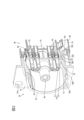
- FIG. 3(a) is a perspective view showing an embodiment of a connector unit as an example of a device unit in this embodiment, FIG. 3(b) is a side view thereof, and FIG. 3(c) is a front view thereof.
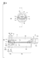
- 4(a) is a rear view of the connector unit shown in FIG. 3(a), and FIG. 4(b) is a cross-sectional view taken along line CC in FIG. 4(a).
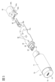
- FIG. 5 is an exploded perspective view of the connector unit shown in FIG. FIG.
- FIG. 6(a) is a perspective view showing the printed circuit board 35 in the connector unit shown in FIG. 3(a), and FIG. 6(b) is a side view of the printed wiring board 30 shown in FIG. 6(a).
- Fig. 7A is a perspective view of the printed circuit board 35 integrally formed with the waterproof seal member 60.
- Fig. 7B is a cross-sectional view of the connector unit 100 cut along a plane including the boundary 30c as viewed from the interface connector 40 side.
- FIG. 8(a) is a rear view showing one embodiment of a connector unit having a rear cover 80
- FIG. 8(b) is a cross-sectional view taken along line CC in FIG. 8(a).
- Figure 9 is a diagram for explaining the water-guiding member 28, where Figure 9(a) is a diagram showing the area from the front panel portion 74 in Figure 3(b) to the section line B-B in the A-A cross-sectional view in Figure 3(c), Figure 9(b) is a B-B cross-sectional view in Figure 3(b), Figure 9(c) is an oblique view of Figure 9(b) viewed from the upper left, and Figure 9(d) is an oblique view of Figure 9(b) viewed from the lower left.
- FIG. 10 is an enlarged view of the area indicated by the dashed line in FIG.
- Fig. 11 is a diagram for explaining drainage holes 76 1 , 76 2 and cutout portion 761 according to the first embodiment.
- FIG. 11(a) is a side view of connector unit 100
- Fig. 11(b) is a Y-Y cross-sectional view of Fig. 11(a)
- Fig. 11(c) is an enlarged view of the area surrounded by the dashed line in Fig. 11(b) in the X-X cross-sectional view of Fig. 11(a)
- Fig. 11(d) is an enlarged view of the area surrounded by the dashed line in Fig. 11(b) in the Z-Z cross-sectional view of Fig. 11(a)
- Fig. 11(e) is a W-W cross-sectional view of Fig. 11(a)
- Fig. 11(a) is a side view of connector unit 100
- Fig. 11(b) is a Y-Y cross-sectional view of Fig. 11(a)
- Fig. 11(c) is an enlarged view of the area surrounded by the dashed line in Fig. 11(b
- FIG. 11(f) is an enlarged view of the area shown by the dashed line in Fig. 11(e).
- Figure 12 is a schematic diagram corresponding to Figure 11(f) showing an example of the effect of drainage by providing a cutout portion 761, where Figure 12(a) shows the case where the cutout portion 761 is not provided and Figure 12(b) shows the case where the cutout portion 761 is provided.
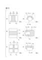
- Figures 13A and 13B are diagrams for explaining drainage holes and cutout portions relating to a modified example of the first embodiment, with Figure 13(a) being a simplified schematic diagram of the vicinity of drainage holes 76-1 and drainage holes 76-2 in Figure 11(a), and Figures 13B to 13F being simplified schematic diagrams of the drainage holes and cutout portions relating to the modified example, similar to Figure 13(a).
- Figure 14 is a diagram for explaining the drainage holes and cutout portions in the second embodiment
- Figure 14(a) is a simplified schematic diagram similar to Figure 13(a)
- Figure 14(b) is a diagram extracting drainage holes 76 1 and 76 2 from Figure 14(a)
- Figure 14(c) is a U-U cross-sectional view
- Figure 14(d) is a V-V cross-sectional view.
- a connector unit is used as an example of an equipment unit.
- the present invention is not limited to a connector unit, and other equipment units may be used as long as the equipment unit has a metal part on the non-waterproof area side described later.
- components having the same function are given the same numbers, and duplicated descriptions will be omitted.
- FIG. 3(a) is a perspective view showing one embodiment of a connector unit as an example of an equipment unit in this embodiment
- FIG. 3(b) is a side view thereof
- FIG. 3(c) is a front view thereof
- FIG. 4(a) is a rear view of the connector unit shown in FIG. 3(a)
- FIG. 4(b) is a cross-sectional view taken along line C-C in FIG. 4(a).
- the potting resin 130 described below is not shown
- FIG. 4(b) the electronic component 50 is not shown.
- FIG. 5 is an exploded perspective view of the connector unit shown in FIG. 3(a).
- the connector unit 100 in this embodiment is configured with the following main elements: a printed wiring board 30, an interface connector 40, electronic components 50, a waterproof seal member 60, a case 70, and a rear connector 91.
- the printed wiring board 30 is a single-layer or multi-layer wiring board made mainly of, for example, glass epoxy resin.
- Figure 6(a) is a perspective view showing the printed circuit board 35 in the connector unit shown in Figure 3(a)
- Figure 6(b) is a side view of the printed wiring board 30 shown in Figure 6(a).
- the printed wiring board 30 in this embodiment has a flat plate shape consisting of a substantially rectangular upper surface 30A and a lower surface 30B facing the upper surface 30A, and has an end 32 having an end face at one end in the length direction, and an end 33 having an end face opposite the end 32.
- the printed wiring board 30 has a first region 30a that extends from the end 32 toward the end 33, and a second region 30b that is adjacent to the first region 30a and extends to the end 33.
- the boundary surface between the first region 30a and the second region 30b is defined as the boundary 30c
- the first region 30a is the region from the end 32 to the boundary 30c in the printed wiring board 30
- the second region 30b is the region from the boundary 30c to the end 33 in the printed wiring board 30.
- the interface connector 40, electronic components 50, and rear connector 91 are mounted on the upper surface 30A of the printed wiring board 30.
- the printed wiring board 30 on which the interface connector 40, electronic components 50, and rear connector 91 are mounted is referred to as the "printed circuit board 35."
- the printed circuit board 35 is housed in a case 70.
- the printed wiring board 30 has two through holes 31b (see FIG. 9).
- the through hole 31b has a circular hole and has two ends, an end 31b1 on the upper surface 30A side and an end 31b2 on the lower surface 30B side (see FIG. 10).
- An interface connector 40 is mounted on the upper surface 30A of the printed wiring board 30 on the end 32 side of the first region 30a, and is connected to a connector of a smartphone or the like.
- the interface connector 40 is a type of electronic component. As shown in Figs. 4 to 6, the interface connector 40 has terminals 42 covered by a shell 41 having a non-watertight structure made of metal, and is positioned so as to face the outside of the case 70 through an opening 73 provided in a front plate portion 74 of the case 70.
- the shell 41 has a first end 41a and a second end 41b.
- the interface connector 40 has two convex portions 43b (see one convex portion 43b shown in Fig.
- the convex portion 43b is inserted into a through hole 31b (Fig. 10) provided in the printed wiring board 30.
- the protrusions 43c and 43d are inserted into the through holes 31c and 31d, respectively.
- the interface connector 40 is positioned on the printed wiring board 30 by inserting the protrusions 43b, 43c, and 43d into the through holes 31b, 31c, and 31d.
- the through holes 31b, 31c, and 31d are holes that penetrate the upper surface 30A and the lower surface 30B of the printed wiring board 30, and are formed as non-through holes here.
- the interface connector 40 in this embodiment is a USB Type-C connector.
- the type of the interface connector 40 is not particularly limited as long as it is an interface connector having a non-watertight structure.
- other interface connectors such as a USB Type-A connector or an HDMI (registered trademark) connector may be used. Since the interface connector 40 has a non-watertight structure, even if the interface connector 40 becomes wet through the opening 73, as long as the amount of water is small, the water will not remain inside the interface connector 40 but will be drained to the outside of the interface connector 40.
- Electronic component 50 On the upper surface 30A of the printed wiring board 30, electronic components 50, which are surface-mount components such as IC chips and capacitors, are mounted on the second region 30b side. As shown in FIG. 6, a plurality of electronic components 50 are mounted on the electronic components 50 in this embodiment.
- the electronic components 50 in this embodiment are different types of electronic components from the interface connector 40 and the rear connector 91 described later.
- the number of electronic components 50 on the printed wiring board 30 is not limited to a plurality.
- the first region 30a side in the case 70 is a non-waterproof region
- the second region 30b side is a waterproof region. Therefore, the electronic components 50 in this embodiment may include electronic components that require higher waterproofing measures than the interface connector 40. Note that if the connector unit 100 of this embodiment can be realized without the electronic components 50, the electronic components 50 do not necessarily have to be mounted.
- FIG. 7(a) is a perspective view of the printed circuit board 35 integrally formed with the waterproof seal member 60.
- Fig. 7(b) is a cross-sectional view seen from the interface connector 40 side when the connector unit 100 is cut along a plane including the boundary 30c.
- the waterproof seal member 60 is formed integrally with the printed wiring board 30 while closely adhering to the printed wiring board 30 and covering the outer periphery 30c1 of the boundary 30c in the printed wiring board 30.
- the waterproof seal member 60 formed on the printed wiring board 30 has pressing surfaces 60A, 60B, 60C, and 60D that press the inner surface of the cylindrical portion 72 when inserted into the case 70.
- the pressing surfaces 60A and 60B, the pressing surfaces 60B and 60C, the pressing surfaces 60C and 60D, and the pressing surfaces 60D and 60A are continuous and form a continuous surface as a whole.
- the pressing surfaces 60A, 60B, 60C, and 60D are the inner periphery of the cylindrical portion 72 of the case 70, and are arranged to be in close contact with the inner surface of the cylindrical portion 72 by pressing the inner periphery 72c that faces the outer periphery 30c1.
- the waterproof seal member 60 separates the inside of the case 70 into a first area 30a side and a second area 30b side.
- the second region 30b side of the case 70 is a waterproof region.
- Specific examples of realizing a waterproof region include injecting potting resin 130 and providing a rear connector 91, as described below.
- the second area 30b side By providing the waterproof seal member 60 and making the second area 30b side inside the case 70 a waterproof area, the second area 30b side exhibits a waterproof function not only when water gets in through the opening 73 of the case 70, but also when water gets in from the rear end side of the case 70 (the side of the case 70 opposite the front panel portion 74). Therefore, no matter what orientation the connector unit 100 is attached to other equipment such as the vehicle in which it is installed, the printed wiring board 30 and electronic components 50 on the second area 30b side inside the case 70 will not be affected by water.
- the waterproof seal member 60 is formed, for example, by insert molding, so as to be integrated with the printed wiring board 30.
- the waterproof seal member 60 is not necessarily limited to being formed as a single member, and may be formed, for example, as multiple non-annular members formed separately from the printed wiring board 30.
- the printed circuit board 35 with the waterproof seal member 60 integrally formed therewith is housed in a case 70.
- the case 70 is a molded product made of a thermoplastic resin such as ABS.
- the waterproof seal member 60 separates the inside of the case 70 into a first region 30a side and a second region 30b side. That is, by implementing a means for realizing a waterproof region, which will be described later, the inside of the case 70 is divided into a non-waterproof region and a waterproof region, with the waterproof seal member 60 as a boundary.
- the case 70 has cylindrical portions 71 and 72 and a front plate portion 74 located at the front end of the cylindrical portion 72.
- the cylindrical portion 71 has a cylindrical shape that is slightly larger than the cylindrical portion 72.
- the front plate portion 74 of the cylindrical portion 72 has an opening 73 through which the mating connector of the interface connector 40 can be inserted and removed.
- the cylindrical portion 72 i.e., the first region 30a side of the case 70, has six drainage holes 76, two on each side surface and two on the bottom surface. In Figs. 3 and 2, subscripts are added to each symbol to identify each drainage hole.
- the openings 73 and drainage holes 76 all lead to the internal space of the cylindrical portion 72.
- the structure of the drainage holes 76 1 to 76 4 will be described in detail later.
- the printed circuit board 35 with the waterproof seal member 60 integrally formed is inserted (pressed) into the case 70 from the rear end side of the cylindrical portion 71 (the side opposite the front panel portion 74 in the case 70).
- sliders 71a, 71b, 71c, and 71d are formed on the inner surface of the cylindrical portion 71 in the left and right side areas.
- the interface connector 40, electronic components 50, waterproof seal member 60, and rear connector 91 excluding the fitting portion 91a on the printed wiring board 30 are housed in the case 70 together with the printed wiring board 30 at a predetermined position and a predetermined height.
- the waterproof seal member 60 separates the inside of the case 70 into a first region 30a side and a second region 30b side. That is, when the waterproof seal member 60 is used as the waterproof seal member, as shown in FIG. 7(b), the pressing surfaces 60A, 60B, 60C, and 60D of the waterproof seal member 60 press against the inner surface of the cylindrical portion 72. In this way, the waterproof seal member 60 separates the inside of the case 70 into a first region 30a side and a second region 30b side.
- the rear connector 91 A rear connector 91 to be connected to a harness connector (not shown) is mounted on the upper surface 30A of the printed wiring board 30 on the end 33 side of the second region 30b.
- the rear connector 91 is a type of electronic component.
- the rear connector 91 is composed of a housing 91A and a terminal 92.
- the housing 91A is cylindrical and includes a fitting portion 91a that fits with the harness connector described above and a base portion 91b that covers the base end of the fitting portion 91a.
- two terminal press-fitting holes 91c are formed in the base portion 91b.
- the rear connector 91 in this embodiment has two terminals 92.
- the terminals 92 are bent into an L-shape, and a pair of protrusions 92a protruding on both sides in the width direction are formed on one side of the L-shape. As shown in FIG. 4 and FIG. 5, the terminals 92 are attached to the housing 91A by pressing one side of the L-shape into the terminal press-fitting hole 91c. One side of the press-fitted terminal 92 is exposed in the fitting portion 91a so as to be connectable to the harness connector described above, while the other side of the L-shape of the terminal 92 is inserted into a through-hole 31a provided on the end portion 33 side of the printed wiring board 30 and connected by soldering.
- the potting resin 130 is injected into the second region 30b side of the case 70.
- the material of the potting resin 130 include, but are not limited to, urethane resin, epoxy resin, and silicon resin.
- the injected potting resin 130 is shown using a symbol, but is shown without a pattern such as diagonal lines so that it can be distinguished from the cylindrical portion 71 and the printed wiring board 30.
- the potting resin 130 is injected until the second region 30b side of the case 70 is filled with the potting resin 130, as shown in FIG. 4B. By filling the potting resin 130, the first region 30a side of the case 70 can be made a non-waterproof region, and the second region 30b side can be made a waterproof region.
- Example 2 for realizing a waterproof area rear cover 80
- the second region 30b side of the case 70 may be left hollow without injecting the potting resin 130, and instead, a rear cover 80 may be provided on the cylindrical portion 71 to provide waterproofing.
- FIG. 8(a) is a rear view showing one embodiment of a connector unit having a rear cover 80
- FIG. 8(b) is a cross-sectional view taken along line C-C in FIG. 8(a).
- the electronic component 50 is not shown.
- the potting resin 130 is not filled on the second region 30b side of the case 70. Instead, the rear end of the cylindrical portion 71 of the case 70, i.e., the end on the second region 30b side of the case 70, is covered by the rear cover 80.
- the rear cover 80 has a circular flat plate having the same shape as the inner diameter of the cylindrical portion 71.
- the contact portion between the rear cover 80 and the case 70 i.e., the inner peripheral surface of the rear end of the cylindrical portion 71 and the outer peripheral surface of the rear cover 80, is firmly bonded with an adhesive or the like.
- the second area 30b side of the case 70 is waterproofed.
- the rear cover 80 When the rear cover 80 is provided, it may be formed so that it is integrated between the fitting portion 91a and the base portion 91b ( Figure 5). As a result, the base portion 91b forms part of the rear cover 80, and the fitting portion 91a protrudes rearward from the rear cover 80.
- the rear cover 80 may be formed as a separate body from the rear connector 91.
- the rear cover 80 may be structured to hold the rear connector 91. It is conceivable that the rear cover 80 is formed from the same material as the waterproof seal member 60, but this is not limited to this.
- the rear cover 80 like the potting resin 130, can provide waterproofing for the second region 30b side of the case 70, and can also provide waterproofing at a lower cost than the potting resin 130.
- FIG. 9 is a diagram for explaining the water guide member 28, in which Fig. 9(a) is a diagram showing the area from the front plate portion 74 in Fig. 3(b) to the cross-sectional line B-B in the A-A cross-sectional view in Fig. 3(c), Fig. 9(b) is a cross-sectional view in Fig. 3(b) taken along the line B-B, Fig. 9(c) is a perspective view of Fig. 9(b) seen from the upper left, and Fig. 9(d) is a perspective view of Fig. 9(b) seen from the lower left.
- Fig. 10 is an enlarged view of the area shown by the dashed line in Fig. 9(a).
- the water guide member 28 is formed below the interface connector 40 on the underside 30B of the printed wiring board 30, starting from the inner surface of the front panel portion 74 and protruding toward the waterproof seal member 60.
- the water guide member 28 is composed of a base 281, two legs 282, and a reinforcing portion 283.
- the base 281 has a flat plate shape that protrudes from the inner surface of the front panel portion 74 toward the waterproof seal member 60 as a square prism with a rectangular bottom.
- the thickness of the base 281, starting from the inner surface of the front panel 74, is constant up to the area having surface 281a, as shown in FIG. 10, and the area having surface 281b is formed so as to become thinner toward the waterproof seal member 60 side. That is, surface 281b is inclined from surface 281a by an angle ⁇ in a direction away from the lower surface 30B.
- the two legs 282 are provided by extending in a curved shape from both ends of the longitudinal direction of the base 281.
- the base 281 and the two legs 282 are connected to each other, forming a C-shape as a whole. At least a part of the base 281 is positioned in a position facing each through hole 31b.
- the legs 282 have a shape that protrudes from the inner surface of the front panel 74 toward the waterproof seal member 60 side by the same length as the base 281.
- the thickness of the leg 282 is constant up to a specified region corresponding to surface 281a, but similar to the base 281, the region corresponding to surface 281b is formed to become thinner toward the waterproof seal member 60 side.
- the reinforcing portion 283 extends from the inner surface of the front plate portion 74 toward the waterproof seal member 60 side, from the center position in the longitudinal direction of the base 281 so as to reinforce the base 281.
- the extension length is formed to be slightly shorter than the base 281.
- the water guide member 28 has an inclined surface (surface 281b) having a predetermined angle (90 degrees - ⁇ ) with respect to the penetrating direction of the through hole 31b, and is arranged so that the shortest distance (distance X in FIG. 10) from the center of gravity of the shape of the end 31b2 is shorter than the radius of the largest circle that can be inserted into the shape of the end 31b2. That is, in the example of FIG. 10, it is provided at a position that maintains the relationship of X ⁇ (D/2). Therefore, when the received water protrudes downward from the end 31b2, the water comes into contact with the water guide member 28.
- the base 281 and the leg 282 with the inclined surface become a flow path, and the water that would have stayed in the through hole 31b flows downward. Therefore, the water guide member 28 drains the water that has entered the through hole 31b of the printed wiring board 30 out of the printed wiring board 30. Additionally, the thinned portion of the base 281, the curved portion of the leg 282, and the thinned portion of the leg 282 guide water toward each part.
- the water guide member 28 is C-shaped with a base 281 and legs 282, and has a reinforcing portion 283 that reinforces the base 281.
- the water guide member 28 is provided in contact with the inner surface of the front plate portion 74. Therefore, even if a force is applied to the front plate portion 74 while the mating connector of the interface connector 40 is being inserted or removed through the opening 73, deformation or damage to the front plate portion 74 is reduced.
- Drainage hole 76, cutout portion 761 Six drainage holes 76 are formed in the cylindrical portion 72. On the right side surface of the cylindrical portion 72 (hereinafter also referred to as the "right side surface of the cylindrical portion 72") as viewed from the front plate portion 74 side (FIG. 3(c)), drainage holes 761 and 762 are formed as a set of drainage holes spaced apart by a predetermined distance from each other in order from the front plate portion 74 side.
- drainage holes 763 and 764 are formed as a set of drainage holes spaced apart by a predetermined distance from each other in order from the front plate portion 74 side.
- drainage holes 765 and 766 are formed as a set of drainage holes spaced apart by a predetermined distance from each other in order from the front plate portion 74 side.
- Each of the drainage holes 76 1 to 76 6 is formed to penetrate from the surface 72A, which is the inner surface, to the surface 72B, which is the outer surface, of the cylindrical portion 72.
- the hole shapes of the drainage holes 76 which are through holes, are approximately rounded quadrilateral hole shapes 76 a, 76 b, 76 c, 76 d, 76 e, and 76 f, in that order of the drainage holes 76 1 to 76 6 .
- a notch 761 is provided between drainage holes 761 and 762 , and between drainage holes 763 and 764.
- drainage holes 761 to 764 and the two notches 761 are formed in a symmetrical structure with the CC cross section shown in Fig. 4A as the reference plane.
- the drainage holes 761 and 762 and the notch 761 provided between drainage holes 761 and 762 will be described. Descriptions of drainage holes 763 and 764 , the notch 761 provided between drainage holes 763 and 764, and drainage holes 765 and 766 which do not have the notch 761 will be omitted.
- FIG. 11 is a diagram for explaining the drainage holes 76 1 , 76 2 and the cutout portion 761 according to the first embodiment.
- Fig. 11(a) is a side view of the connector unit 100
- Fig. 11(b) is a Y-Y cross-sectional view of Fig. 11(a)
- Fig. 11(c) is an enlarged view of the area surrounded by the dashed line in Fig. 11(b) in the X-X cross-sectional view of Fig. 11(a)
- Fig. 11(d) is an enlarged view of the area surrounded by the dashed line in Fig. 11(b) in the Z-Z cross-sectional view of Fig. 11(a)
- Fig. 11(a) is a side view of the connector unit 100
- Fig. 11(b) is a Y-Y cross-sectional view of Fig. 11(a)
- Fig. 11(c) is an enlarged view of the area surrounded by the das
- FIG. 11(e) is a W-W cross-sectional view of Fig. 11(a)
- Fig. 11(f) is an enlarged view of the area surrounded by the dashed line in Fig. 11(e).
- the water guide member 28 and the printed wiring board 30 visible from the drainage holes 76 1 and 76 2 are not shown in Fig. 11(a).
- a cutout portion 761 having a length L2 (Fig. 11(f)) is provided between the pair of drainage holes 761 and 762.
- the cutout portion 761 has a hole shape that expands the hole shape of the drainage hole while contacting a part of the circumference of the hole shape from the middle of the drainage hole in the penetration direction to the outer surface of the case.
- the cutout portion 761 is formed so that the drainage hole 761 and the drainage hole 762 are cut out from a position that is a length L1 away from the surface 72A, which is on the way from the inner surface (surface 72A) of the cylindrical portion 72 to the outer surface (surface 72B) in the penetration direction, and cuts out the cylindrical portion 72 by a length (length L2) from the surface 72A to the surface 72B.
- the cutout portion 761 has a substantially rectangular hole shape 761a that expands the hole shape 76a and the hole shape 76b while contacting the ends 761a and 762a (see FIG. 13A ) that are part of the circumference of the drainage hole ( 761 , 762 ) at a position away from the surface 72A by a length L1. That is, the cutout portion 761 is formed so as to cut out the tubular portion 72 by a length L2 in the penetration direction (the direction penetrating from the surface 72A to the surface 72B) while having the hole shape 761a, starting from the ends 761a and 762a . As a result, the cutout portion 761 forms a substantially rectangular parallelepiped space (opening) having the hole shape 761a.
- the size and shape of the drainage holes 761 and 762 change at the boundary of the position of length L1 (i.e., starting from the ends 761a and 762a ).
- the drainage holes 761 and 762 have the shapes and sizes of hole shapes 76a and 76b, respectively, from the surface 72A to the ends 761a and 762a at the distance of length L1.
- the hole shapes of the drainage holes 761 and 762 are a shape in which the three hole shapes of hole shape 76a, hole shape 761a, and hole shape 76b are connected in the portion of length L2 from the ends 761a and 762a to the surface 72B.
- the hole shapes of drainage holes 761 and 762 become discontinuous from the position of length L1 (ends 761a , 762a ) which is halfway in the penetration direction, and the shape and size change from two hole shapes having hole shapes 76a and 76b to one hole shape having the size of hole shape 76a + hole shape 761a + hole shape 76b.
- FIG. 12 is a schematic diagram corresponding to FIG. 11(f) showing an example of the effect of the cutout portion 761 on drainage, in which FIG. 12(a) shows a case where the cutout portion 761 is not provided and FIG. 12(b) shows a case where the cutout portion 761 is provided.
- the connector unit 100 is assumed to be used by being attached to, for example, a motorcycle or other vehicle, and the posture of the use state is not necessarily maintained in the state shown in FIG. 3. That is, the connector unit 100 can be used in various postures depending on the usage form of the user. Therefore, in the following description, the description will be based on the posture in which the penetration direction of the drainage hole 76 and the direction of gravity coincide, which is considered to promote drainage the most.
- the direction of gravity (G) in FIG. 12 is vertically upward when FIG. 12 is viewed from the front. Additionally, the openings of drainage holes 76 1 and 76 2 on the surface 72A side are referred to as drainage holes 76 1-IN and 76 2- IN , and the openings on the surface 72B side are referred to as drainage holes 76 1-OUT and 76 2-OUT .
- Water received by opening 73 travels through interface connector 40 and printed wiring board 30 to reach surface 72A inside cylindrical portion 72. Alternatively, it reaches surface 72A directly from interface connector 40. Some of the water that reaches surface 72A enters drainage holes 76 1-IN and 76 2-IN and flows into drainage holes 76 1-OUT and 76 2-OUT .
- the connector unit 100 is formed with certain restrictions on the shape and size of the drain holes 76 to prevent foreign matter from entering the cylindrical portion 72.
- One cause of the trapping phenomenon is when the size of the hole shape of the drain holes 76 cannot be sufficiently ensured, and the liquid does not become large enough to drip.
- the size of the hole shape suddenly expands from hole shape 76a or hole shape 76b to hole shape 76a + hole shape 761a + hole shape 76b at the position of length L1, i.e., at the ends 761a and 762a (see FIG. 13(a)).
- This sudden change is not in all directions around the drainage hole, but is limited to a certain direction, namely, the ends 761a and 762a (see FIG. 13(a)).
- the drainage holes 761 and 762 are cut out in predetermined ranges around the hole shapes 76a and 76b.
- the water that has entered the drainage holes 76 1-IN and 76 2-IN maintains its flow direction from surface 72A to surface 72B, but is trapped at the ends 76 1 a and 76 2 a (i.e., the cut-out peripheral area).
- the drainage holes 76 1 and 76 2 continue all the way to surface 72B, so the water tends to continue to flow in the penetration direction.
- other water flows in later, accelerating the above-mentioned situation.
- the direction of the tip surface of the water near the ends 76 1 a and 76 2 a is tilted at a certain angle from the penetration direction toward the cut-out area.
- the water that sticks to the periphery of the uncut side will be closer to surface 72B than the water that sticks to the periphery of the cut-out side, and as a result, the tip surface of the water near ends 76 1 a, 76 2 a will tend to face in a direction that is obliquely inclined relative to the penetration direction.
- the diameter of the droplets that remain near the ends 76 1 a and 76 2 a tends to be larger than when the cutouts 761 are not provided. If droplets with a larger diameter are generated than when the cutouts 761 are not provided, the weight of the droplets becomes heavier than that shown in FIG. 12(a), and the surface tension becomes weaker, making it easier to drip. Therefore, by providing the cutouts 761, the trapping phenomenon can be avoided.
- the droplets of water that have been received from the drainage holes 76 1 and 76 2 come into contact with each other at the cutouts 761, and become even larger droplets.
- the drainage holes 761 , 762 have a larger hole shape on the surface 72B side, but the hole shape on the surface 72A side still maintains the size of the original hole shapes 76a, 76b, so there is no increased risk of foreign matter being mixed in.
- the diameter of droplets generated from the stagnant water can be increased and made to drip more easily than when no cutout portion is provided, so that water that has entered the drainage hole can be actively drained into the device without increasing the risk of foreign matter entering the inside of the device.
- Fig. 13 is a diagram for explaining drainage holes and cutouts according to a modification of the first embodiment
- Fig. 13(a) is a schematic diagram showing the vicinity of drainage holes 76 1 and 76 2 in Fig. 11(a) in a simplified manner
- Figs. 13(b) to 13(f) are schematic diagrams showing the drainage holes and cutouts according to the modification in a simplified manner similar to Fig. 13(a).
- the areas of the cutouts are shown using dotted lines in order to distinguish between the drainage holes and the cutouts.
- the direction of gravity (G) in Fig. 13 is the vertical forward direction when Fig. 13 is viewed from the front.
- the drainage holes may be arranged vertically in the above-mentioned cylindrical portion 72.
- a drainage hole 761 may be provided horizontally on the right side surface of the cylindrical portion 72, and a drainage hole 762 may be provided horizontally below the drainage hole 761 (i.e., vertically) at a predetermined distance from the drainage hole 761 , with a notch 761 formed therebetween.
- the fact that the arrangement direction of the drainage holes is not important has the advantage of increasing the freedom of design.
- the number of sets of drainage holes provided in the cylindrical portion 72 may be more than one.
- two sets of drainage holes (drainage holes 76 1-1 , 76 2-1 and drainage holes 76 1-2 , 76 2-2 ) may be provided that are spaced apart from each other by a predetermined distance, and the sets of drainage holes may also be spaced apart from each other by a predetermined distance.
- a cutout portion 761 2 having a substantially cross-shaped hole shape 761 2 a is formed between each drainage hole.
- only drainage holes having a hole shape smaller than the above-mentioned drainage holes 76 1 , 76 2 are provided.
- the cutout portion may be provided for each drainage hole.
- one drainage hole may be formed to have a hole shape that expands the hole shape while contacting at least half of the circumference of the hole shape of the drainage hole from the middle of the penetration direction to the outside of the case.
- the cutout portion 761 3 is formed to have a hole shape 761 3 a that expands the hole shape 76g while contacting an end portion 76 3 a that corresponds to at least half of the circumference of the drainage hole 76 1-3 .
- the cutout portion 761 3 is a cutout portion dedicated to the drainage hole 76 1-3 and is not shared with other drainage holes. Therefore, FIG. 13(d) has a higher degree of freedom in the direction and shape of the cutout of the cylindrical portion 72 compared to FIG. 13(a), and the degree of freedom in design is higher.
- Fig. 13(e) is another example in which the length of the end 76 3 a is secured to be more than half the circumference of the drainage hole 76 1-3 .
- the cutout 76 1 4 contacts the end 76 4 a (three sides and four corners of the rounded rectangle), which is the majority of the circumference of the drainage hole 76 1-4 having a rounded rectangular hole shape 76 h, but does not contact the end 76 4 b.
- the cutout 76 1 4 has a hole shape 76 1 4 a that expands the rounded rectangular hole shape 76 h.
- drain hole 761-4 most of drain hole 761-4 is contained within cutout 761-4 , but the surface in the penetrating direction including end 764b of drain hole 761-4 forms a continuous surface from surface 72A to surface 72B. Therefore, water not only stays in cutout 761-4 , but also continues to flow in the drain direction, providing a dripping effect.
- the cutout portion When the cutout portion has a rounded rectangular hole shape, it may be formed so as to include and contact at least one side of the circumference of the drainage hole 76 and both corners of the both ends. For example, as shown in FIG. 13( f ), the cutout portion 761 5 contacts one longitudinal side of the drainage hole 76 1 -5 having a rounded rectangular hole shape 76i and an end 76 5 a including both corners of the both ends.
- the cutout portion 761 5 has a hole shape 761 5 a.
- the cutout portion 761 5 When the cutout portion 761 5 can secure a hole shape of approximately the same size as or larger than the hole shape 761 5 a, the cutout portion 761 5 may be formed so as to contact one lateral side of the drainage hole 76 1 -5 and an end including both corners of the both ends.
- the hole shape must be a rounded rectangle, this has the advantage of allowing greater freedom in design than Figure 13(d) in that it is not restricted by the condition that the cutout portion must be in contact with at least half of the circumference of the drain hole.
- the cutout portion in the first embodiment and its modified example described above has a hole shape that expands the hole shape while contacting a predetermined range on the circumference of the hole shape of the drain hole from midway in the penetration direction (from surface 72A to surface 72B) to the outside of the cylindrical portion 72 that constitutes the case 70.
- the cutout portion cuts out a predetermined range on the circumference of the hole shape of the drain hole from midway in the penetration direction to the outside of the case 70.
- the second embodiment is configured to obtain the same effect as the first embodiment by not providing a cutout portion, but by providing a protrusion 77 that extends further outward from a portion of the circumference of the drainage hole beyond the outer surface (surface 72B) of the tubular portion 72.
- Fig. 14 is a diagram for explaining the drainage holes and cutouts according to the second embodiment
- Fig. 14(a) is a schematic diagram in a simplified form similar to Fig. 13(a)
- Fig. 14(b) is a diagram in which drainage holes 76 1 and 76 2 are extracted from Fig. 14(a)
- Fig. 14(c) is a U-U cross-sectional view
- Fig. 14(d) is a V-V cross-sectional view.
- this embodiment like the first embodiment, there is a pair of drainage holes 76 1 and 76 2 .
- the cylindrical portion 72 in the second embodiment has a protruding portion 77.
- the protruding portion 77 is provided on the outer surface (surface 72B) of the cylindrical portion 72, and is connected to three sides that are part of the circumference of each of the drainage holes 76 1 and 76 2 and two corners (ends 76 1 b, 76 2 b) between them, and protrudes further outward from the surface 72B with a plate thickness t, surrounding a pair of drainage holes 76 1 and 76 2.
- the length L3 of the protrusion is appropriately adjusted with reference to the length L2 ( FIG. 12 ).
- the drainage holes 76 1 and 76 2 are illustrated by dotted lines, and the ends 76 1 b and 76 2 b are illustrated by thick lines.
- the drain holes 76 1 and 76 2 extend further outward from the surface 72B.
- an opening 761 6 is formed, which is a space having a hole shape 761 6 a. That is, two holes, hole shape 76 1 a and hole shape 76 2 a, are formed from the surface 72A to the surface 72B, but from the surface 72B to the outside, one hole shape (hole shape 76 1 a + hole shape 761 6 a + hole shape 76 2 a) is formed.
- the opening 761 6 can also be said to be a predetermined range cut out from the drain holes 76 1 and 76 2 around the hole shapes 76 1 a and 76 2 a. Therefore, the opening 7616 has the same function as the notch 761, and can actively drain water that has entered the drain hole inside the device without increasing the risk of foreign matter entering the inside of the device.
- the opening 761-6 has the same function as the notch 761. Therefore, instead of providing a notch in Figs. 13(a) to (c), a protrusion may be provided in which the area corresponding to the notch protrudes further outward from the surface 72B.
- a protrusion may be provided in which the area corresponding to the notch protrudes further outward from the surface 72B.
- the area corresponding to the notch 761 may be provided as a protrusion so as to protrude further outward from the surface 72B.
- the area corresponding to the notch 761-2 may be provided as a protrusion so as to protrude further outward from the surface 72B.
- the protrusion may be provided for each drain hole, similar to the cutout 761. Therefore, instead of providing a cutout in Figs. 13(d) to (f), a protrusion may be provided in which an area corresponding to the cutout protrudes further outward from the surface 72B.
- a protrusion may be provided in which an area corresponding to the cutout protrudes further outward from the surface 72B.
- an area secured from the end 76 3 a by a predetermined thickness for example, thickness t
- a predetermined thickness for example, thickness t
- an area secured from the end 76 4 a by a predetermined thickness may be provided as a protrusion so as to protrude further outward from the surface 72B.
- a predetermined thickness for example, thickness t
- an area secured by a predetermined thickness e.g., thickness t
- a predetermined thickness e.g., thickness t
- the protrusions in the second embodiment and its modified example described above are provided on the outer surface (surface 72B) of the cylindrical portion 72 constituting the case 70, and protrude from the cylindrical portion 72 in the penetration direction (from surface 72A to surface 72B) while contacting a predetermined range around the drain hole.
- water that has entered the drain hole in the device can be actively drained without increasing the risk of foreign matter entering the inside of the device.
- the hole shape of the drainage hole 76 is not limited to the above-mentioned shape and may be other hole shapes.
- the hole shapes of the drainage holes 76 1 , 76 2 , 76 1-1 , 76 2-1 , 76 1-2 , 76 2-2 , 76 1-4 are not limited to a rounded rectangle and may be other hole shapes such as a circle or an ellipse.
- the hole shape of the drainage hole 76 1-3 is not limited to a circle and may be other shapes such as a rounded rectangle or an ellipse.
- the cutout portion 761 may be provided between the drainage holes 76 5 and 76 6 formed on the bottom surface of the tubular portion 72. Needless to say, the connector unit 100 described in this embodiment can be appropriately modified within the scope of the present invention.
Landscapes
- Engineering & Computer Science (AREA)
- Microelectronics & Electronic Packaging (AREA)
- Connector Housings Or Holding Contact Members (AREA)
- Casings For Electric Apparatus (AREA)
- Motor Or Generator Frames (AREA)
Abstract
Description
以下、本発明の第1の実施の形態について図面を参照して説明する。この説明では、機器ユニットとしてコネクタユニットを例に用いた場合について説明する。但し、本発明は、後述する非防水領域側に金属部品を備えた機器ユニットであれば、その種類は特にコネクタユニットに限定されず、他の機器ユニットでもよい。なお、以降の説明において、同じ機能を有する構成部には同じ番号を付し、重複説明を省略する。
プリント配線板30は、例えばガラスエポキシ樹脂を主材料とした単層あるいは多層からなる配線板である。図6(a)は図3(a)に示したコネクタユニットにおいて、プリント回路板35を示した斜視図であり、図6(b)は図6(a)に示したプリント配線板30の側面図である。
プリント配線板30の上面30A上には、第1の領域30aの端部32側に、例えばスマートフォン等のコネクタと接続されるインタフェースコネクタ40が実装されている。インタフェースコネクタ40は電子部品の一種である。図4から図6に示すように、インタフェースコネクタ40は、端子42が金属製の非水密構造からなるシェル41で覆われており、ケース70の前面板部74に設けられている開口部73を介してケース70の外側に臨むように位置されている。シェル41は、第1端部41aと第2端部41bとを有する。インタフェースコネクタ40は、底面の端部41b側に2つの凸部43b(図10に示した1つの凸部43bを参照)、シェル41の両側面には、端部41a側から順に凸部43c、43d(図6(a))を備えている。凸部43bは、プリント配線板30に設けられた貫通穴31b(図10)に挿入されている。同様に、凸部43c,43dは、それぞれ貫通穴31c,31dに挿入されている。凸部43b、43c、43dが、貫通穴31b、31c、31dに挿入されることで、インタフェースコネクタ40がプリント配線板30上に位置決めされることとなる。貫通穴31b、31c、31dは、プリント配線板30の上面30Aと下面30Bとを貫通する穴であり、ここではノンスルーホールとして形成されている。本実施形態におけるインタフェースコネクタ40は、USB Type-Cコネクタである。但し、非水密構造を有するインタフェースコネクタであれば、インタフェースコネクタ40の種類は特に限定されない。例えば、USB Type-Aコネクタや、HDMI(登録商標)コネクタ等の他のインタフェースコネクタを用いてもよい。インタフェースコネクタ40は非水密構造を有していることから、開口部73を介してインタフェースコネクタ40が被水したとしても、少量の被水である限りにおいては、被水はインタフェースコネクタ40内には滞留せず、インタフェースコネクタ40の外側に排水されることとなる。
プリント配線板30の上面30Aには、第2の領域30b側に、例えばICチップやコンデンサなどの表面実装部品である電子部品50が実装されている。本実施形態における電子部品50は、図6に示すように複数の電子部品50が実装されている。本実施形態における電子部品50は、インタフェースコネクタ40や後述する後面コネクタ91とは別の種類の電子部品である。但し、プリント配線板30上の電子部品50の点数は複数に限定されるものではない。また、後述するように、本実施形態では、ケース70内の第1の領域30a側を非防水領域とし、第2の領域30b側を防水領域とする。したがって、本実施形態における電子部品50の中には、インタフェースコネクタ40よりも高い防水対策が求められる電子部品が含まれていてもよい。なお、本実施形態のコネクタユニット100が、電子部品50が無くても実現できるような場合であれば、必ずしも電子部品50が実装されていなくても良い。
プリント配線板30には、境界30cの外周30c1上に、ホットメルト材からなる防水シール部材60が形成されている。図7(a)は、防水シール部材60が一体形成されたプリント回路板35の斜視図である。図7(b)は、コネクタユニット100を境界30cを含む面で切断した場合のインタフェースコネクタ40側から見た断面図である。
防水シール部材60が一体形成されたプリント回路板35は、ケース70内に収容されている。ケース70は、例えばABS等の熱可塑性樹脂で形成された成型品である。既述の通り、防水シール部材60は、ケース70内を第1の領域30a側と第2の領域30b側とに隔離する。即ち、後述する防水領域を実現する手段を施すことにより、ケース70は、防水シール部材60を境に、ケース70内を非防水領域と防水領域とに区分けされる。
プリント配線板30の上面30Aには、第2の領域30bの端部33側に、ハーネスコネクタ(不図示)と接続される後面コネクタ91が実装されている。後面コネクタ91は電子部品の一種である。後面コネクタ91は、図5に示すように、ハウジング91Aと、端子92とから構成されている。ハウジング91Aは筒状をなし、上述したハーネスコネクタと嵌合される嵌合部91aと、嵌合部91aの基端を蓋する基部91bよりなる。基部91bには、図4(a)に示すように、端子圧入穴91cが2つ形成されている。本実施形態における後面コネクタ91は、2本の端子92を有している。端子92はL字状に折り曲げられた形状を有し、L字の一辺には幅方向両側に突出する一対の突起92aが形成されている。図4及び図5に示したように、端子92はL字の一辺が端子圧入穴91cに圧入されてハウジング91Aに取り付けられている。圧入された端子92の一辺は、上述したハーネスコネクタと接続できるように、嵌合部91a内で露出した状態になっている。一方、端子92のL字の他辺はプリント配線板30の端部33側に設けられたスルーホール31aに挿入されてはんだ付け接続されている。
防水シール部材60とプリント回路板35とがケース70内に収容された後に、ケース70内の第2の領域30b側にポッティング樹脂130を注入する。ポッティング樹脂130の材質としては、例えば、ウレタン樹脂、エポキシ樹脂、シリコン樹脂が挙げられるがこれに限定されるものではない。図4(b)には注入されたポッティング樹脂130を符号を用いて示しているが、筒状部71やプリント配線板30と識別できるように、斜線等を用いずに模様を付さないで示している。ポッティング樹脂130の注入は、図4(b)に示すように、ケース70内の第2の領域30b側がポッティング樹脂130により充填されるまで行う。このポッティング樹脂130の充填により、ケース70内の第1の領域30a側を非防水領域とし、第2の領域30b側を防水領域とすることができる。
ケース70内の第2の領域30b側を、ポッティング樹脂130を注入することなく中空状態とし、これに代わり筒状部71に後面カバー80を設けて防水化を図るように構成してもよい。
筒状部72には導水部材28が形成されている。図9は、導水部材28を説明するための図であって、図9(a)は、図3(c)におけるA-A断面図において図3(b)の前面板部74から断面線B-Bまでの領域を表示した図であり、図9(b)は図3(b)におけるB-B断面図であり、図9(c)は図9(b)を左上方向から見た斜視図であり、図9(d)は図9(b)を左下方向から見た斜視図である。図10は、図9(a)の一点鎖線で示した領域内の拡大図である。
筒状部72には、6つの排水穴76が形成されている。前面板部74側(図3(c))から見て筒状部72の右側側面(以下、「筒状部72の右側側面」ともいう。)には、前面板部74側から順番に、排水穴761及び排水穴762が、互いが所定の距離だけ離れて一組の排水穴として形成されている。前面板部74側から見て筒状部72の左側側面(以下、「筒状部72の左側側面」ともいう。)には、前面板部74側から順番に、排水穴763及び排水穴764が、互いが所定の距離だけ離れて一組の排水穴として形成されている。前面板部74側から見て筒状部72の底面には、前面板部74側から順番に、排水穴765及び排水穴766が、互いが所定の距離だけ離れて一組の排水穴として形成されている。各排水穴761~766は、筒状部72の内側の面である面72Aから外側の面である面72Bへ貫通するように形成されている。貫通穴である排水穴76の穴形状は、排水穴761~766の順に、略角丸四辺形の穴形状76a、76b、76c、76d、76e、76fを有する。
図13は、第1の実施の形態の変形例に係る排水穴及び切り欠き部を説明するための図であり、図13(a)は、図11(a)において、排水穴761と排水穴762の近傍を簡略化して表した模式図、図13(b)~図13(f)は、変形例に係る排水穴及び切り欠き部を図13(a)と同様に簡略化して表した模式図である。図13では、排水穴と切り欠き部とを識別するために、切り欠き部の領域を点線模様を用いて示している。図13における重力の方向(G)は、図13を正面から見て、垂直手前方向であるとする。
第2の実施の形態は、切り欠き部を設けずに、排水穴の周の一部を、筒状部72の外側の面(面72B)から更に外側に張り出す突出部77を設けることにより、第1と同様の効果を得る構成としたものである。
上述したように、開口部7616は切り欠き部761と同等の機能を有する。したがって、図13(a)~(c)において、切り欠き部を設ける代わりに、切り欠き部に相当する領域を、面72Bから更に外側に突出させた突出部を設けてもよい。例えば、図13(b)に示した、排水穴761と排水穴762が設けられている場合、切り欠き部761を設ける代わりに、切り欠き部761に相当する領域を面72Bから更に外側に突出するように突出部として設けてもよい。また、図13(c)に示した、排水穴761-1,762-1、及び排水穴761-2,762-2が設けられている場合、切り欠き部7612を設ける代わりに、切り欠き部7612に相当する領域を面72Bから更に外側に突出するように突出部として設けてもよい。
30A 上面 30a 第1の領域
30B 下面 30b 第2の領域
30c 境界 30c1 外周
31a スルーホール 31b~31d 貫通穴
31b1、31b2 端部 31bJ 軸
32、33 端部 35 プリント回路板
40 インタフェースコネクタ 41 シェル
41a、41b 端部 42 端子
43b~43d 凸部 50 電子部品
60 防水シール部材 60A~60D 押圧面
70 ケース 71、72 筒状部
71a~71d スライダ 72c 内周
72A、72B 面 73 開口部
74 前面板部 76 排水穴
761a~765a 端部 761b、762b 端部
76a~76i 穴形状 761a 穴形状
7612a~7616a 穴形状 761 切り欠き部
7612~7615 切り欠き部 7616 開口部
77 突出部 80 後面カバー
91 後面コネクタ 91A ハウジング
91a 嵌合部 91b 基部
91c 端子圧入穴 92 端子
92a 突起 100 コネクタユニット
130 ポッティング樹脂 281 基部
281a、281b 面 282 脚部
282a、282b 面 283 補強部
D 直径 L1、L2 長さ
t 厚さ X 距離
Claims (9)
- 内部が防水領域と、非防水領域とに区分けされたケースと、
前記ケースの非防水領域内に実装された金属製部品と、
を備え、
前記ケースは、
前記非防水領域側に設けられ、前記金属製部品の被水を排出するために、前記ケースの内側から外側へ貫通する第1穴形状を有した排水穴と、
前記排水穴において、貫通方向の途中から前記ケースの外側に至るまで、前記第1穴形状の周における予め定めた範囲を切り欠いた切り欠き部と、
を有する機器ユニット。 - 前記切り欠き部における、前記第1穴形状の周における予め定めた範囲とは、前記第1穴形状の周の少なくとも半分である、
請求項1に記載の機器ユニット。 - 前記排水穴における前記第1穴形状は、角丸四辺形であり、
前記切り欠き部における、前記第1穴形状の周における予め定めた範囲とは、前記角丸四辺形の穴形状の少なくとも一辺とその両端の角である、
請求項1に記載の機器ユニット。 - 内部が防水領域と、非防水領域とに区分けされたケースと、
前記ケースの非防水領域内に実装された金属製部品と、
を備え、
前記ケースは、
前記非防水領域側に互いが所定の距離だけ離れて設けられ、前記金属製部品の被水を排出するために、夫々が前記ケースの内側から外側へ貫通する第1穴形状を有した一組の排水穴と、
前記一組の排水穴の間に設けられ、夫々の前記排水穴の貫通方向の途中から前記ケースの外側に至るまで、前記排水穴の夫々の周の一部と接しつつ、前記第1穴形状を拡げる第2穴形状を有した切り欠き部と、
を有する機器ユニット。 - 内部が防水領域と、非防水領域とに区分けされたケースと、
前記ケースの非防水領域内に実装された金属製部品と、
を備え、
前記ケースは、
前記非防水領域側に設けられ、前記金属製部品の被水を排出するために、前記ケースの内側から外側へ貫通する第1穴形状を有した排水穴と、
前記ケースの外側の面に設けられ、前記第1穴形状の周における予め定めた範囲と接しつつ、前記ケースから貫通方向へ突出する突出部と、
を有する機器ユニット。 - 前記突出部における、前記第1穴形状の周における予め定めた範囲とは、前記第1穴形状の周の少なくとも半分である、
請求項5に記載の機器ユニット。 - 内部が防水領域と、非防水領域とに区分けされたケースと、
前記ケースの非防水領域内に実装された金属製部品と、
を備え、
前記ケースは、
前記非防水領域側に互い所定の距離だけ離れて設けられ、前記金属製部品の被水を排出するために、夫々が前記ケースの内側から外側へ貫通する第1穴形状を有した一組の排水穴と、
前記ケースの外側の面における前記一組の排水穴の間に設けられ、前記排水穴の夫々の周の一部と連接しつつ、前記ケースから貫通方向へ突出する突出部と、
を有する機器ユニット。 - 前記突出部は、前記ケースの外側の面に設けられ、前記排水穴の夫々の周の一部と連接しつつ前記一組の排水穴を囲んで前記ケースから貫通方向へ突出する、
請求項7に記載の機器ユニット。 - 前記排水穴の穴形状は、円形、長円形、または角丸四辺形のいずれかである、
請求項1から2、または請求項4から8のいずれかに記載の機器ユニット。
Priority Applications (3)
| Application Number | Priority Date | Filing Date | Title |
|---|---|---|---|
| US19/143,068 US20260106401A1 (en) | 2023-02-01 | 2023-12-07 | Equipment unit |
| EP23919927.6A EP4611182A4 (en) | 2023-02-01 | 2023-12-07 | DEVICE UNIT |
| CN202380089854.9A CN120391019A (zh) | 2023-02-01 | 2023-12-07 | 机器单元 |
Applications Claiming Priority (2)
| Application Number | Priority Date | Filing Date | Title |
|---|---|---|---|
| JP2023014027A JP7536914B1 (ja) | 2023-02-01 | 2023-02-01 | 機器ユニット |
| JP2023-014027 | 2023-02-01 |
Publications (1)
| Publication Number | Publication Date |
|---|---|
| WO2024161792A1 true WO2024161792A1 (ja) | 2024-08-08 |
Family
ID=92146327
Family Applications (1)
| Application Number | Title | Priority Date | Filing Date |
|---|---|---|---|
| PCT/JP2023/043779 Ceased WO2024161792A1 (ja) | 2023-02-01 | 2023-12-07 | 機器ユニット |
Country Status (6)
| Country | Link |
|---|---|
| US (1) | US20260106401A1 (ja) |
| EP (1) | EP4611182A4 (ja) |
| JP (1) | JP7536914B1 (ja) |
| CN (1) | CN120391019A (ja) |
| TW (1) | TWI904521B (ja) |
| WO (1) | WO2024161792A1 (ja) |
Citations (2)
| Publication number | Priority date | Publication date | Assignee | Title |
|---|---|---|---|---|
| JP2017208227A (ja) | 2016-05-18 | 2017-11-24 | 住友電装株式会社 | 車両側コネクタ |
| JP2019204598A (ja) * | 2018-05-21 | 2019-11-28 | 日本航空電子工業株式会社 | コネクタユニット |
Family Cites Families (8)
| Publication number | Priority date | Publication date | Assignee | Title |
|---|---|---|---|---|
| JPS6130312Y2 (ja) * | 1978-06-27 | 1986-09-05 | ||
| JPS59134897A (ja) * | 1983-01-20 | 1984-08-02 | 松下電器産業株式会社 | 電気器具の排水装置 |
| JPH11266516A (ja) * | 1998-01-16 | 1999-09-28 | Sumitomo Wiring Syst Ltd | 配電ボックス |
| JP4096255B2 (ja) * | 2003-06-24 | 2008-06-04 | 住友電装株式会社 | 電線カバー |
| JP5741945B2 (ja) * | 2011-09-14 | 2015-07-01 | 住友電装株式会社 | 電気接続箱 |
| EP3778362B1 (en) * | 2018-03-29 | 2023-09-06 | Honda Motor Co., Ltd. | Usb terminal unit structure for saddle riding-type vehicle |
| CN114503793B (zh) * | 2019-10-16 | 2023-11-14 | 三菱电机株式会社 | 电气设备装置 |
| JP7278928B2 (ja) * | 2019-11-15 | 2023-05-22 | 京セラ株式会社 | 電気機器用ケース及び蓄電装置 |
-
2023
- 2023-02-01 JP JP2023014027A patent/JP7536914B1/ja active Active
- 2023-12-07 US US19/143,068 patent/US20260106401A1/en active Pending
- 2023-12-07 WO PCT/JP2023/043779 patent/WO2024161792A1/ja not_active Ceased
- 2023-12-07 EP EP23919927.6A patent/EP4611182A4/en active Pending
- 2023-12-07 CN CN202380089854.9A patent/CN120391019A/zh active Pending
- 2023-12-15 TW TW112148990A patent/TWI904521B/zh active
Patent Citations (2)
| Publication number | Priority date | Publication date | Assignee | Title |
|---|---|---|---|---|
| JP2017208227A (ja) | 2016-05-18 | 2017-11-24 | 住友電装株式会社 | 車両側コネクタ |
| JP2019204598A (ja) * | 2018-05-21 | 2019-11-28 | 日本航空電子工業株式会社 | コネクタユニット |
Non-Patent Citations (1)
| Title |
|---|
| See also references of EP4611182A4 |
Also Published As
| Publication number | Publication date |
|---|---|
| JP7536914B1 (ja) | 2024-08-20 |
| TW202433815A (zh) | 2024-08-16 |
| EP4611182A4 (en) | 2026-03-18 |
| US20260106401A1 (en) | 2026-04-16 |
| JP2024116432A (ja) | 2024-08-28 |
| TWI904521B (zh) | 2025-11-11 |
| CN120391019A (zh) | 2025-07-29 |
| EP4611182A1 (en) | 2025-09-03 |
Similar Documents
| Publication | Publication Date | Title |
|---|---|---|
| US6390854B2 (en) | Resin shield circuit device | |
| US7950931B2 (en) | Electrical junction box with drainage portions | |
| CN109315073B (zh) | 基板单元 | |
| CN111316505B (zh) | 电路装置 | |
| JP2024017071A (ja) | コネクタユニット、及び車載用コネクタ装置 | |
| US4574297A (en) | Encapsulated semiconductor with terminals having tabs to increase solder wetting | |
| JP7536914B1 (ja) | 機器ユニット | |
| JP7654046B1 (ja) | コネクタユニット | |
| JP7654047B1 (ja) | コネクタユニット | |
| WO2025088881A1 (ja) | コネクタユニット | |
| JP2018125334A (ja) | 電子制御装置 | |
| CN119732189A (zh) | 电子设备 | |
| JP7100983B2 (ja) | コネクタ及び電子機器 | |
| JP6972710B2 (ja) | 継電器 | |
| US20250218705A1 (en) | Switch device | |
| JP3501192B2 (ja) | 表面実装型電子ユニットパッケージ | |
| JPH08167438A (ja) | 回路基板用の接続部材 | |
| KR100743319B1 (ko) | 표면 실장형 반도체 장치 및 그 제조 방법 | |
| JP2000068656A (ja) | 筐体構造 | |
| JPH09162316A (ja) | 面実装パッケージ | |
| JP2005302430A (ja) | 素子内蔵コネクタ及びコネクタ |
Legal Events
| Date | Code | Title | Description |
|---|---|---|---|
| 121 | Ep: the epo has been informed by wipo that ep was designated in this application |
Ref document number: 23919927 Country of ref document: EP Kind code of ref document: A1 |
|
| WWE | Wipo information: entry into national phase |
Ref document number: 2023919927 Country of ref document: EP |
|
| ENP | Entry into the national phase |
Ref document number: 2023919927 Country of ref document: EP Effective date: 20250530 |
|
| WWE | Wipo information: entry into national phase |
Ref document number: 202517060712 Country of ref document: IN |
|
| WWE | Wipo information: entry into national phase |
Ref document number: 202380089854.9 Country of ref document: CN |
|
| WWP | Wipo information: published in national office |
Ref document number: 202380089854.9 Country of ref document: CN |
|
| WWP | Wipo information: published in national office |
Ref document number: 202517060712 Country of ref document: IN |
|
| NENP | Non-entry into the national phase |
Ref country code: DE |
|
| WWP | Wipo information: published in national office |
Ref document number: 2023919927 Country of ref document: EP |