WO2024162155A1 - Feuille d'électrode pour condensateurs électrolytiques, condensateur électrolytique et procédé de fabrication d'une feuille d'électrode pour condensateurs électrolytiques - Google Patents
Feuille d'électrode pour condensateurs électrolytiques, condensateur électrolytique et procédé de fabrication d'une feuille d'électrode pour condensateurs électrolytiques Download PDFInfo
- Publication number
- WO2024162155A1 WO2024162155A1 PCT/JP2024/002143 JP2024002143W WO2024162155A1 WO 2024162155 A1 WO2024162155 A1 WO 2024162155A1 JP 2024002143 W JP2024002143 W JP 2024002143W WO 2024162155 A1 WO2024162155 A1 WO 2024162155A1
- Authority
- WO
- WIPO (PCT)
- Prior art keywords
- porous portion
- foil
- electrode foil
- main surface
- hardness
- Prior art date
- Legal status (The legal status is an assumption and is not a legal conclusion. Google has not performed a legal analysis and makes no representation as to the accuracy of the status listed.)
- Ceased
Links
Images


Classifications
-
- H—ELECTRICITY
- H01—ELECTRIC ELEMENTS
- H01G—CAPACITORS; CAPACITORS, RECTIFIERS, DETECTORS, SWITCHING DEVICES, LIGHT-SENSITIVE OR TEMPERATURE-SENSITIVE DEVICES OF THE ELECTROLYTIC TYPE
- H01G9/00—Electrolytic capacitors, rectifiers, detectors, switching devices, light-sensitive or temperature-sensitive devices; Processes of their manufacture
- H01G9/004—Details
- H01G9/04—Electrodes or formation of dielectric layers thereon
- H01G9/048—Electrodes or formation of dielectric layers thereon characterised by their structure
- H01G9/055—Etched foil electrodes
-
- H—ELECTRICITY
- H01—ELECTRIC ELEMENTS
- H01G—CAPACITORS; CAPACITORS, RECTIFIERS, DETECTORS, SWITCHING DEVICES, LIGHT-SENSITIVE OR TEMPERATURE-SENSITIVE DEVICES OF THE ELECTROLYTIC TYPE
- H01G9/00—Electrolytic capacitors, rectifiers, detectors, switching devices, light-sensitive or temperature-sensitive devices; Processes of their manufacture
- H01G9/145—Liquid electrolytic capacitors
-
- H—ELECTRICITY
- H01—ELECTRIC ELEMENTS
- H01G—CAPACITORS; CAPACITORS, RECTIFIERS, DETECTORS, SWITCHING DEVICES, LIGHT-SENSITIVE OR TEMPERATURE-SENSITIVE DEVICES OF THE ELECTROLYTIC TYPE
- H01G9/00—Electrolytic capacitors, rectifiers, detectors, switching devices, light-sensitive or temperature-sensitive devices; Processes of their manufacture
- H01G9/15—Solid electrolytic capacitors
Definitions
- This disclosure relates to electrode foil for electrolytic capacitors, electrolytic capacitors, and methods for manufacturing electrode foil for electrolytic capacitors.
- the electrode foil of an electrolytic capacitor contains a valve metal and has a porous portion and a core portion that is continuous with the porous portion.
- the porous portion provides an electrode foil with a large surface area, increasing the capacity of the electrolytic capacitor.
- Patent Document 1 proposes an electrode foil for aluminum electrolytic capacitors in which aluminum foil that has been subjected to a surface expansion treatment by etching is compressed in the foil thickness direction, thereby increasing the surface area per unit volume compared to before compression.
- an electrode foil for an electrolytic capacitor comprising a metal foil containing a valve action metal, the metal foil having a core and a porous portion continuous with the core, the porous portion having a main surface of the metal foil, and a hardness X of the porous portion measured by a nanoindentation method at a maximum indentation load of 100 mN on the main surface being 40 mN/mm2 or more .
- an electrolytic capacitor comprising a capacitor element, the capacitor element comprising a winding body and an electrolyte, the winding body being configured by winding an anode foil, a cathode foil, and a separator disposed between the anode foil and the cathode foil, the anode foil comprising the above-mentioned electrode foil and a dielectric layer covering a metal skeleton constituting the porous portion of the electrode foil.
- Yet another aspect of the present disclosure relates to a method for producing an electrode foil for an electrolytic capacitor, the method including: etching a sheet containing a valve metal to form a porous portion on a main surface of the sheet; and compressing the sheet after the etching in a thickness direction to form the porous portion having a hardness X of 40 mN/ mm2 or more, wherein the hardness X is the hardness when a maximum indentation load on the main surface is 100 mN, as measured by a nanoindentation method.
- This disclosure makes it possible to obtain a highly reliable, high-capacity electrolytic capacitor.
- FIG. 1 is a cross-sectional view illustrating a schematic example of an electrode foil for an electrolytic capacitor according to an embodiment of the present disclosure.
- FIG. 2 is a diagram illustrating an example of a compression step in a method for producing an electrode foil for an electrolytic capacitor according to an embodiment of the present disclosure.
- FIG. 1 is a cross-sectional view illustrating a schematic example of an electrolytic capacitor according to an embodiment of the present disclosure.
- FIG. 4 is a perspective view showing a schematic configuration of a wound body in the electrolytic capacitor of FIG. 3 .
- the electrode foil for electrolytic capacitors includes a metal foil containing a valve metal.
- the metal foil has a core and a porous portion continuous with the core.
- the porous portion has a main surface of the metal foil.
- the hardness X hereinafter also simply referred to as "hardness X"
- hardness X of the porous portion measured by a nanoindentation method when the maximum indentation load on the main surface is 100 mN is 40 mN/ mm2 or more.
- the porous portion contains many pores (pits), and in order to increase capacity, it is conceivable to increase the pit density or the thickness of the porous portion to increase the surface area of the foil.
- increasing the pit density or the thickness of the porous portion reduces the strength of the electrode foil, which can lead to cracks in the electrode foil or cuts in the foil during the manufacturing process of the electrolytic capacitor.
- the reduction in strength of the electrode foil is due to a reduction in the strength of the surface layer of the porous portion, and this reduction in strength of the surface layer is particularly noticeable when the pit density or thickness of the porous portion is high.
- the following (a) to (c) are presumed to be factors that reduce the strength of the surface layer of the porous portion.
- the surface layer is likely to deteriorate when the etching solution comes into contact with the surface of the metal foil during electrolytic etching.
- the stress that occurs when the metal foil is rolled during the manufacturing process of the electrolytic capacitor is likely to become large on the surface layer of the metal foil. This stress becomes large, for example, when the diameter of the roller that rolls up the metal foil is small. Furthermore, this stress is larger on the outer periphery side of the rolled metal foil than on the inner periphery side.
- Rolled foil is usually used for long sheets containing valve metals used as the raw material for the metal foil (e.g., raw aluminum foil), which have rolling marks and are likely to remain on the surface layer of the porous portion even after etching.
- the hardness X of the porous portion can be increased by compressing the etching foil, etc.
- the hardness X may be increased by adjusting the etching conditions (such as the amount of dissolution of the sheet surface) to suppress deterioration of the surface layer and decrease in strength during etching, but in a high-capacity electrode foil with a large porous layer thickness, it is difficult to increase the hardness X to 40 mN/ mm2 or more by simply adjusting the etching conditions.
- the hardness X may be increased by combining the adjustment of the etching conditions with the compression conditions, etc.
- the hardness X is 40 mN/ mm2 or more
- the decrease in strength of the surface layer when the pit density or the thickness of the porous portion is increased is suppressed, and the tensile strength of the electrode foil is increased.
- the capacity per unit volume is sufficiently increased.
- the hardness X is 40 mN/ mm2 or more, preferably 54 mN/ mm2 or more, and more preferably 57 mN/ mm2 or more. If the hardness of the porous layer is high, the density (occupancy rate) of the metal skeleton of the porous layer increases, the pits become smaller, and the actual surface area of the porous portion becomes smaller, so that the strength increases but the capacitance of the electrode foil decreases. Therefore, from the viewpoint of suppressing the decrease in capacitance, the hardness X may be, for example, 85 mN/ mm2 or less, or 75 mN/ mm2 or less.
- the elastic modulus indicates the ease of deformation of a material, and in the elastic deformation range, the stress and strain applied to the material are generally proportional to each other, with the elastic modulus being the proportional constant (Hooke's law).
- the higher the hardness the higher the elastic modulus.
- the higher the hardness the higher the elastic modulus.
- the elastic modulus is also an important parameter from the viewpoint of increasing the strength of the electrode foil for an electrolytic capacitor.
- the elastic modulus of the porous part when the maximum indentation load on the main surface of the metal foil (porous part) is 100 mN, as measured by the nanoindentation method, is preferably 520 mN/mm 2 or more, more preferably 560 mN/mm 2 or more, and even more preferably 580 mN/mm 2 or more.
- the upper limit of the elastic modulus is, for example, 800 mN/mm 2 or less.
- the elastic modulus can be increased within the above range by appropriately adjusting the thickness of the etched foil (porous part) to be compressed and the thickness reduction rate during compression.
- the amount of creep indicates how easily a material deforms when a constant load is applied for a constant period of time.
- the greater the amount of creep the higher the tensile strength.
- the amount of creep is an important parameter from the viewpoint of increasing the strength of electrode foil for electrolytic capacitors.
- the amount of creep in the porous portion when the maximum indentation load on the main surface of the metal foil (porous portion) is 100 mN, as measured by the nanoindentation method is preferably 5% or more, more preferably 5.3% or more, and even more preferably 5.4% or more.
- the upper limit of the amount of creep is, for example, 6.5% or less. The greater the rate of thickness reduction during compression, the greater the amount of creep tends to be.
- the hardness X, elastic modulus, and creep amount of the porous portion are determined by the nanoindentation method in accordance with ISO 14577-1 (2014). An indenter is pressed into the main surface of the metal foil having a porous portion, and an indentation load is applied up to 100 mN. The hardness X and elastic modulus are measured based on the indentation behavior of the indenter into the porous portion at this time. The creep amount is determined by the change in indentation depth when the maximum load of 100 mN is held for 5 seconds.
- the creep amount (%) is calculated as (h2-h1)/h1 x 100.
- the measurement conditions are as follows:
- Measuring device Ultra-micro indentation hardness tester "ENT-5" manufactured by Elionix Co., Ltd. Ambient temperature: 30°C Indenter: Berkovich type diamond indenter Test load (maximum pressing load): 100 mN Measurement points: 3 points are averaged.
- the electrode foil sample is fixed to a sample stage using STE TAPE manufactured by SHINTO PAINT.
- the porous portion has a thickness T (thickness per one side of the metal foil) and has an inner layer region on the core side and a surface layer region on the opposite side to the core.
- the surface layer region is a region that is a distance of T/4 or less from the outer surface of the porous portion when the porous portion has a thickness T ( ⁇ m).
- the inner layer region is a region that is a distance of T/4 or less from the boundary between the porous portion and the core.
- the ratio D 1 /D 2 of the average diameter D 1 to the average diameter D 2 is preferably 0.98 or less, more preferably 0.95 or less, and may be 0.9 or less.
- D 1 /D 2 is preferably 0.5 or more, more preferably 0.55 or more, may be 0.6 or more, or may be 0.7 or more.
- the range of D 1 /D 2 may be a range that combines the above upper and lower limits arbitrarily, for example, 0.5 or more and 0.98 or less, and more preferably 0.55 or more and 0.95 or less. When the hardness X is within the above range, D 1 /D 2 is easy to adjust to 0.98 or less.
- the above average diameter D1 and average diameter D2 can be determined as follows.
- (i) A cross-sectional image of the electrode foil is obtained by a scanning electron microscope (SEM). Using the image, the thickness of the porous portion is measured at any ten points, and the average value is calculated to be the thickness T of the porous portion.
- the surface region is defined as a region that is a distance of T/4 or less from the outer surface of the porous portion (surface S1 in FIG. 1).
- a cross-sectional image of the surface region is obtained, and the image is subjected to a binarization process to distinguish between the metal skeleton region constituting the surface region and the pore (pit) region other than the metal skeleton region.
- a point in the pore region of the surface layer region is arbitrarily selected, a line segment passing through the selected point and crossing the pore region is drawn, and the length of the line segment at the shortest length is measured. This measurement is performed for 20 points in the pore region of the surface layer region, and the average value of the obtained measurements is calculated to be the average diameter D1 of the pores in the surface layer region.
- the region that is at a distance of T/4 or less from the boundary between the porous portion and the core portion (surface B in FIG. 1) is defined as the inner layer region.
- the average diameter D2 of the pores in the inner layer region is also determined in the same manner as in (iii) and (iv) above.
- the porosity P1 of the surface layer region is likely to be smaller than the porosity P2 of the inner layer region.
- the ratio P1 / P2 of the porosity P1 to the porosity P2 is preferably 0.95 or less, more preferably 0.92 or less, and may be 0.85 or less.
- P1 / P2 is preferably 0.5 or more, more preferably 0.55 or more, may be 0.6 or more, or may be 0.7 or more.
- the range of P1 / P2 may be a range that combines the above upper and lower limits arbitrarily, for example, 0.5 or more and 0.95 or less, and more preferably 0.55 or more and 0.92 or less. When the hardness X is within the above range, P1 / P2 is easily adjusted to 0.95 or less.
- the porosity P1 of the surface region is determined by measuring the area S0 of the entire region of the cross-sectional image of the surface region after the binarization process in (iii) obtained in the process of determining the average diameter D1, and the area S1 of the region occupied by the pores in the image, and calculating ( S1 / S0 ) x 100.
- the porosity P2 of the inner layer region is determined in the same manner as above.
- the surface roughness Ra of the metal foil (roughness of the outer surface of the porous portion) is preferably 1.5 ⁇ m or less, more preferably 0.1 ⁇ m or more and 1.5 ⁇ m or less, and may be 0.5 ⁇ m or more and 1.5 ⁇ m or less.
- the surface roughness Ra of the metal foil means the arithmetic mean roughness, and the arithmetic mean roughness Ra is determined in accordance with JIS B 0601:2001.
- the surface roughness Ra of the metal foil When the surface roughness Ra of the metal foil is reduced to 1.5 ⁇ m or less by the compression process described below, the effects of the rolling marks can be sufficiently reduced.
- the surface roughness of the metal foil can be made smaller than the surface roughness based on the rolling marks of the original foil, and unnecessary oxides along the rolling marks can be removed. Furthermore, when the surface roughness Ra of the metal foil is 0.1 ⁇ m or more, the surface area of the metal foil is sufficiently secured, making it easy to increase the capacity.
- V S1 /V 0 In the pore distribution of the porous portion measured by mercury intrusion porosimetry, it is preferable that the relationship V S1 /V 0 ⁇ 0.07 is satisfied. It is further preferable that the relationship V S2 /V 0 ⁇ 0.05 (or 0.04) is satisfied. When the hardness X is within the above range, V S1 /V 0 (and further V S2 /V 0 ) is likely to be within the above range.
- V0 is the cumulative pore volume ( cm3 /g) when the pore diameter is 0.01 ⁇ m or more and 1 ⁇ m or less.
- Vs1 is the cumulative pore volume ( cm3 /g) when the pore diameter is 0.01 ⁇ m or more and 0.06 ⁇ m or less.
- Vs2 is the cumulative pore volume ( cm3 /g) when the pore diameter is 0.01 ⁇ m or more and 0.05 ⁇ m or less.
- an AutoPore V series manufactured by Micromeritics is used to measure the pore distribution.
- Small pores with a pore diameter of 0.01 ⁇ m or more and 0.06 ⁇ m or less (or 0.05 ⁇ m or less) are easily blocked by the dielectric layer, which is disadvantageous in terms of increasing capacity, reducing ESR, and strength.
- the portion where the pores are blocked by the dielectric layer not only does not contribute to improving the capacity, but also becomes hard and brittle. If the number of small pores and the number of blocked portions increase, the strength of the electrode foil decreases, and the electrode foil may crack or break during the manufacturing process of the electrolytic capacitor (transporting the electrode foil, slitting, winding, connection with the lead member by crimping, etc.).
- V S1 /V 0 (and further V S2 /V 0 ) is within the above range, there are few small pores and many pores having a pore diameter suitable for improving the capacity are distributed, making it easy to increase the capacity. In this case, the number of blocked portions is small, making it easy to suppress a decrease in strength.
- VL1 / V0 ⁇ 0.4 is satisfied, and more preferably the relationship VL2 / V0 ⁇ 0.1 (or 0.08) is satisfied.
- VL1 / V0 (and furthermore VL2 / V0 ) is likely to be within the above range.
- V L1 is the cumulative pore volume (cm 3 /g) for pores with diameters of 0.16 ⁇ m or more and 1 ⁇ m or less
- V L2 is the cumulative pore volume (cm 3 /g) for pores with diameters of 0.5 ⁇ m or more and 1 ⁇ m or less.
- V L1 /V 0 (and further V L2 /V 0 ) is within the above range, there are few large pores and many pores having a pore diameter suitable for improving the capacity are distributed, making it easy to increase the surface area of the electrode foil and to increase the capacity.
- the thickness T A of the metal foil is, for example, 60 ⁇ m or more, preferably 90 ⁇ m or more, more preferably 110 ⁇ m or more, and even more preferably 120 ⁇ m or more.
- the thickness T A of the metal foil may be 200 ⁇ m or less.
- the thickness T of the porous portion may be 25 ⁇ m or more and 90 ⁇ m or less, or 35 ⁇ m or more and 80 ⁇ m or less.
- the thickness of the core portion may be, for example, 20 ⁇ m or more, or 25 ⁇ m or more.
- the thickness TA of the metal foil is large (for example, when it is 90 ⁇ m or more or 120 ⁇ m or more), the stress generated in the metal foil (surface layer) during winding becomes large, and therefore, when the hardness X is within the above range, the effect of improving the strength of the surface layer (the effect of suppressing the occurrence of cracks due to the stress) is significantly obtained.
- the metal foil contains a valve metal.
- valve metals include aluminum (Al), tantalum (Ta), and niobium (Nb).
- the metal foil may be a foil of a valve metal (e.g., Al), or may be a foil containing an alloy or compound containing a valve metal (e.g., Al).
- a dielectric layer may be formed so as to cover the metal skeleton that constitutes the porous portion.
- the dielectric layer is, for example, a layer containing an oxide of the valve metal.
- FIG. 1 is a cross-sectional view that shows a schematic example of an electrode foil for electrolytic capacitors according to one embodiment of the present disclosure.
- FIG. 1 shows a cross section in the thickness direction of the electrode foil. Note that the electrode foil for electrolytic capacitors according to the present disclosure is not limited to this.
- the electrode foil contains a valve metal and has a core 330, and a first porous portion 310 and a second porous portion 320 connected to the core 330.
- the metal foil 300 has a first main surface S1 and a second main surface S2 opposite the first main surface S1.
- the first porous portion 310 and the second porous portion 320 are formed to sandwich the core 330.
- the first porous portion 310 has the first main surface S1 of the metal foil 300.
- the second porous portion 320 has the second main surface S2 of the metal foil 300.
- a dielectric layer is formed by chemical conversion treatment or the like to cover the surfaces of the metal skeletons that constitute the first porous portion 310 and the second porous portion 320.
- At least one of the first hardness X1 of the first porous portion 310 and the second hardness X2 of the second porous portion 320 is a hardness X within the above range.
- the first hardness X1 is the hardness of the first porous portion 310 when the maximum indentation load on the first main surface S1 is 100 mN, measured by a nanoindentation method.
- the second hardness X2 is the hardness of the second porous portion 320 when the maximum indentation load on the second main surface S2 is 100 mN, measured by a nanoindentation method.
- At least one of the first hardness X1 and the second hardness X2 may be a hardness X within the above range. It is preferable that both the first hardness X1 and the second hardness X2 are hardness X within the above range.
- the first hardness X1 is usually approximately the same as the second hardness X2 , but may be different.
- the porous portion 310 has a thickness T ( ⁇ m) and includes an inner layer region 312 on the core portion 330 side and a surface layer region 311 on the opposite side to the core portion 330.
- the surface layer region 311 is a region that is a distance of T/4 or less from the outer surface S1 of the porous portion 310.
- the inner layer region 312 is a region that is a distance of T/4 or less from the boundary B between the porous portion 310 and the core portion 330.
- the first hardness X1 is a hardness X within the above range
- the average diameter D1 (nm) of the pores in the surface layer region 311 can be smaller than the average diameter D2 (nm) of the pores in the inner layer region 312. The same can be said about the porous portion 320 (the surface layer region 321 and the inner layer region 322).
- the method for producing an electrode foil for an electrolytic capacitor includes an etching step of etching a sheet containing a valve metal to form a porous portion on a main surface of the sheet, and a compression step of compressing the etched sheet in the thickness direction to form a porous portion having a hardness X of 40 mN/ mm2 or more.
- the hardness X is the hardness measured by a nanoindentation method when the maximum indentation load on the main surface is 100 mN.
- the sheet used in the etching process contains a valve metal.
- valve metals include Al, Ta, and Nb.
- the raw material sheet may be a sheet of a valve metal (e.g., Al), or may be a sheet containing an alloy or compound containing a valve metal (e.g., Al).
- a long or strip-shaped rolled sheet (rolled foil) is usually used as the raw material sheet.
- the etching process forms a porous portion on the main surface of the sheet, and the other portion remains as a core.
- the sheet has a core and a porous portion that is continuous with the core, and the porous portion has the main surface of the sheet.
- the porous portion is usually formed on both main surfaces of the sheet, sandwiching the core.
- the compression process the sheet having the porous portion formed by the etching process is compressed.
- the surface layer of the porous portion has low strength and is easily compressed in the compression process.
- the thickness of the porous portion (particularly the surface layer) is reduced by compression. It is acceptable for the thickness of the core to be slightly smaller before and after compression, but it is desirable for it to remain almost the same.
- the hardness X, D1 / D2 , P1/P2, Vs1 / V0 , Vs2 / V0 , VL1 / V0 , VL2 / V0 , etc. can be controlled within the above-mentioned ranges.
- the sheet comes into contact with processing liquids (e.g., etching liquid, chemical conversion liquid) and rollers, which can cause unevenness (or scratches).
- processing liquids e.g., etching liquid, chemical conversion liquid
- rollers which can cause unevenness (or scratches).
- stress can concentrate on the unevenness, causing the sheet to break (or cracks to form in the sheet).
- the aluminum foil used in the sheet has rolling marks that occur during the manufacturing process, and etching pits can be formed unevenly along the rolling marks, i.e., along the length direction (rolling direction) of the long sheet.
- the rolling marks can cause the sheet to break (or cracks to form in the sheet).
- the thickness T A of the sheet may be 90 ⁇ m or more and 200 ⁇ m or less, or 120 ⁇ m or more and 200 ⁇ m or less.
- the thickness T of the porous portion per side may be 25 ⁇ m or more and ⁇ (T A /2)-10 ⁇ ⁇ m or less.
- the core portion can be secured with a sufficient thickness.
- the thickness T may be 25 ⁇ m or more and 90 ⁇ m or less, or 35 ⁇ m or more (or 40 ⁇ m or more) and 80 ⁇ m or less.
- the thickness T of the porous portion is large, and the effect of improving the surface layer strength by compression is significantly obtained.
- a high-capacity foil is used, and the thickness T A of the sheet (electrode foil) is preferably 90 ⁇ m or more or 120 ⁇ m or more, and the thickness T of the porous portion per side is preferably 25 ⁇ m or more or 35 ⁇ m or more (or 40 ⁇ m or more).
- the etching step the surface of the sheet containing the valve metal is etched to roughen the surface of the sheet and form a porous portion continuous with the core.
- the etching may be electrolytic etching or chemical etching, and may be performed using a known method.
- the hardness X can be adjusted to some extent by changing the etching conditions.
- the electrolytic etching may be performed at a current density of 2.0 A/ cm2 or less, 1.5 A/ cm2 or less, or 1.2 A/ cm2 or less.
- the current density may be changed during etching. The larger the pore diameter, the easier it is to form a thicker dielectric layer, and this is advantageous in terms of increasing the voltage.
- the electrolytic etching is preferably AC etching, but DC etching may also be used.
- AC etching is more likely to form porous areas that contain sponge-like pits with relatively small diameters.
- DC etching is more likely to form porous areas that contain tunnel-like pits with relatively large diameters.
- the temperature of the etching solution may be set to 10° C. or more and 60° C. or less between 0 and 0.7T E , and may be set to 5° C. or more and 40° C. or less between 0.7T E and T E . In this case, the variation in the pit diameter in the thickness direction of the porous portion can be reduced.
- the etching time T E is, for example, 15 minutes or more and 30 minutes or less.
- the etched sheet may be conveyed between a pair of rollers and compressed.
- the etched sheet conveyed between the pair of rollers is compressed by the pressure of the pair of rollers.
- the pair of rollers may be arranged in multiple stages to compress the sheet in stages.
- the diameter of the pair of rollers may be changed for each stage, or may be made smaller as the sheet is compressed.
- the compression process may include a process of conveying the sheet by the rollers and a process of winding up the compressed sheet. The compression increases the strength of the surface layer of the sheet, and prevents the sheet from breaking when it is wound up by the rollers.
- Fig. 2 is a configuration diagram showing an example of the compression process.
- Arrow X in Fig. 2 indicates the conveying direction of the long sheet 400.
- a compression device shown in Fig. 2 is used.
- the compression device includes a pair of rollers 500 that compresses the sheet 400.
- the sheet 400 having a thickness T B (mm) after the etching process is compressed to a thickness T A (mm) by pressing with the pair of rollers 500.
- the sheet sending speed may be 0.5 m/min or more, or may be 0.5 m/min or more and 50 m/min or less.
- the thickness reduction rate of the sheet in the compression step is preferably 5% or more and 40% or less, more preferably 10% or more (or 12% or more) and 30% or less, and even more preferably 10% or more and 25% or less.
- the thickness reduction rate is a value calculated by ⁇ (T B -T A )/T B ⁇ 100 when the thickness of the sheet is reduced from T B to T A by compression.
- the contact area 410 between the roller 500 and the sheet 400 is arc-shaped, and the central angle ⁇ of the roller 500 with respect to the arc of the contact area 410 may be 0.15° or more and 1.5° or less (or 1.75° or less).
- the length L of the projection area in the conveying direction X of the sheet 400 may be 0.5 mm or more and 5 mm or less.
- the sheet 400 may be compressed with a linear pressure of 0.55 kN/cm or more and 14 kN/cm or less.
- the diameter D of the roller 500 may be 75 mm or more and 1800 mm or less.
- the thickness T 0 (mm) of the porous portion of the sheet 400 before compression and the diameter D (mm) of the roller 500 may satisfy the relationship 380 ⁇ D/T 0 ⁇ 9800.
- the device may further include a roller for transporting the sheet 400, and may also include a roller for winding up the compressed sheet 400.
- the device may also include a control unit for controlling the rotation speed of the rollers 500, etc.
- the control unit may also control the feed speed of the sheet 400.
- the manufacturing method of the electrode foil may include a step of slitting the compressed sheet.
- the slitting process uses a slitting device and a roller that winds up the slitted sheet.
- the compression increases the strength of the surface layer of the sheet, and prevents the sheet from breaking when it is wound up by the roller.
- the electrode foil for electrolytic capacitor according to the embodiment of the present disclosure is suitable for use in an electrolytic capacitor including a wound capacitor element.
- the wound capacitor element includes a wound body and an electrolyte.
- the wound body is configured by winding an anode foil, a cathode foil, and a separator disposed between the anode foil and the cathode foil.
- the anode foil includes an electrode foil according to the embodiment of the present disclosure (hereinafter also referred to as "electrode foil A”) and a dielectric layer covering a metal skeleton that constitutes a porous portion of the electrode foil A.
- electrolytic capacitors with a rated voltage of 20V or more aluminum foil that has been chemically treated at a chemical voltage of 30V or more is used as the anode foil.
- aluminum foil that has been chemically treated at a chemical voltage of 30V or more is often used as the anode foil.
- an electrode foil with a relatively large pit diameter is used, and a dielectric layer with a relatively large thickness (for example, a thickness of 45 nm or more) is formed, and the strength of the surface layer is likely to decrease.
- the electrode foil A has a significant effect of improving the surface layer strength.
- the formed chemical film becomes thick, so by using an electrode foil with a large pit diameter, the blocking of the pits by the thick chemical film is suppressed, and high capacity can be efficiently achieved.
- the anode foil includes an electrode foil A and a dielectric layer covering a metal skeleton constituting the porous portion of the electrode foil A.
- the dielectric layer is obtained, for example, by forming an oxide film of a valve metal on the surface of the metal skeleton constituting the porous portion by anodization (chemical conversion treatment).
- the chemical conversion voltage may be, for example, 5 V or more, or 40 V or more.
- the main surface of the anode foil may have a first main surface and a second main surface opposite to the first main surface.
- the porous portion may include a first porous portion having a first main surface and a second porous portion having a second main surface, sandwiching the core portion.
- the dielectric layer may include a first dielectric layer covering the metal skeleton constituting the first porous portion and a second dielectric layer covering the metal skeleton constituting the second porous portion.
- at least one of the first hardness X 1 of the first porous portion and the second hardness X 2 of the second porous portion may have a hardness X within the above range. It is preferable that both the first hardness X 1 and the second hardness X 2 are hardness X within the above range.
- the first hardness X 1 may be greater than the second hardness X 2 , and at least the first hardness X 1 may have a hardness X within the above range.
- the anode foil is wound such that the first main surface of the first porous portion having the first hardness X1 faces the outer periphery of the wound body.
- the tensile stress generated during winding is greater on the main surface on the outer periphery of the wound body, and therefore the effect of improving the strength of the surface layer (the effect of suppressing the occurrence of cracks during winding) can be significantly obtained.
- the thickness of the anode foil may be 60 ⁇ m or more and 200 ⁇ m or less, preferably 90 ⁇ m or more and 200 ⁇ m or less, and more preferably 120 ⁇ m or more and 200 ⁇ m or less.
- the thickness of the dielectric layer is, for example, 45 nm or more.
- the cathode foil may be a metal foil containing a valve metal such as Al, Ta, or Nb. If necessary, the surface of the metal foil may be roughened by etching. That is, the cathode foil may be a metal foil having a porous portion and a core portion continuous with the porous portion.
- the electrode foil for electrolytic capacitors according to the present disclosure may be used for the cathode foil.
- the thickness of the cathode foil is, for example, 10 ⁇ m or more and 70 ⁇ m or less.
- the separator is not particularly limited, and may be, for example, a nonwoven fabric containing fibers of cellulose, polyethylene terephthalate, vinylon, or polyamide (for example, aliphatic polyamide, aromatic polyamide such as aramid).
- the electrolyte covers at least a portion of the anode foil (dielectric layer) and is interposed between the anode foil (dielectric layer) and the cathode foil.
- the electrolyte includes at least one of a solid electrolyte and an electrolytic solution.
- the capacitor element may include a solid electrolyte, or may include a solid electrolyte and a liquid component (electrolytic solution or a non-aqueous solvent).
- the dielectric layer is covered with an electrolyte by, for example, impregnating the anode foil (or wound body) with a treatment solution (or electrolyte solution) containing a conductive polymer.
- a treatment solution or electrolyte solution
- the average diameter D1 is smaller than the average diameter D2 (and the porosity P1 is smaller than the porosity P2 ), so that the treatment solution impregnated in the porous portion tends to remain in the pores, and the inner walls of the pores tend to be covered with the electrolyte, improving the contact between the anode foil (dielectric layer) and the electrolyte.
- the solid electrolyte includes a conductive polymer.
- the conductive polymer include ⁇ -conjugated polymers.
- Examples of the conductive polymer include polypyrrole, polythiophene, polyfuran, polyaniline, etc.
- the conductive polymer may be used alone or in combination of two or more types, or may be a copolymer of two or more types of monomers.
- the weight-average molecular weight of the conductive polymer is, for example, 1,000 to 100,000.
- polypyrrole, polythiophene, polyfuran, polyaniline, etc. refer to polymers having polypyrrole, polythiophene, polyfuran, polyaniline, etc. as their basic skeletons, respectively. Therefore, polypyrrole, polythiophene, polyfuran, polyaniline, etc. may also include their respective derivatives.
- polythiophene includes poly(3,4-ethylenedioxythiophene), etc.
- the conductive polymer may be doped with a dopant.
- the solid electrolyte may contain a dopant together with the conductive polymer. Examples of dopants include polystyrene sulfonic acid.
- the solid electrolyte may further contain an additive as necessary.
- the liquid component may be an electrolyte or a non-aqueous solvent.
- the electrolyte contains a non-aqueous solvent and an ionic substance (solute (e.g., an organic salt)) dissolved therein.
- the non-aqueous solvent may be an organic solvent or an ionic liquid.
- the non-aqueous solvent is preferably a high boiling point solvent.
- a high boiling point solvent for example, polyol compounds such as ethylene glycol, sulfone compounds such as sulfolane, lactone compounds such as ⁇ -butyrolactone, ester compounds such as methyl acetate, carbonate compounds such as propylene carbonate, ether compounds such as 1,4-dioxane, ketone compounds such as methyl ethyl ketone, etc. can be used.
- the liquid component may contain an acid component (anion) and a base component (cation).
- a salt may be formed by the acid component and the base component.
- the acid component contributes to the film repair function.
- the acid component include organic carboxylic acids and inorganic acids.
- inorganic acids include phosphoric acid, boric acid, and sulfuric acid.
- the base component include primary to tertiary amine compounds.
- An organic salt is a salt in which at least one of the anion and cation contains an organic substance.
- organic salts include trimethylamine maleate, triethylamine borodisalicylate, ethyldimethylamine phthalate, mono 1,2,3,4-tetramethylimidazolinium phthalate, and mono 1,3-dimethyl-2-ethylimidazolinium phthalate.
- the liquid component contains more acid components than base components. Also, since the acid components contribute to the film repair function of the liquid component, it is preferable that the liquid component contains more acid components than base components.
- the molar ratio of the acid component to the base component: (acid component/base component) is, for example, 1.1 or more.
- the pH of the liquid component may be 6 or less, or may be 1 or more and 5 or less.
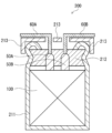
- FIG. 3 is a cross-sectional view that shows a schematic example of an electrolytic capacitor according to an embodiment of the present disclosure.
- FIG. 4 is a perspective view that shows a schematic configuration of a wound body in the electrolytic capacitor of FIG. 3.
- the electrolytic capacitor 200 comprises a capacitor element, which comprises a wound body 100 and an electrolyte (not shown).
- the wound body 100 is formed by winding an anode foil 10 and a cathode foil 20 with a separator 30 interposed therebetween.
- lead tabs 50A and 50B are connected to the anode foil 10 and the cathode foil 20, respectively, and the wound body 100 is formed by winding the lead tabs 50A and 50B.
- Lead wires 60A and 60B are connected to the other ends of the lead tabs 50A and 50B, respectively.
- a stop tape 40 is placed on the outer surface of the cathode foil 20 located at the outermost layer of the wound body 100, and the end of the cathode foil 20 is fixed by the stop tape 40.
- the wound body 100 may be further subjected to a chemical conversion treatment in order to provide a dielectric layer on the cut surface.
- An electrolyte is interposed between the anode foil 10 (dielectric layer) and the cathode foil 20 in the wound body 100.
- the capacitor element is obtained, for example, by impregnating the wound body 100 with a treatment liquid containing an electrolyte. The impregnation may be performed under reduced pressure, for example, in an atmosphere of 10 kPa to 100 kPa.
- the wound body 100 is housed in the bottomed case 211 so that the lead wires 60A and 60B are located on the opening side of the bottomed case 211.
- the material of the bottomed case 211 can be a metal such as aluminum, stainless steel, copper, iron, brass, or an alloy of these metals.
- the wound body 100 is sealed in the bottomed case 211 by placing a sealing member 212 at the opening of the bottomed case 211 that contains the wound body 100 and the electrolyte, crimping the open end of the bottomed case 211 to the sealing member 212 and curling it, and placing a seat plate 213 on the curled portion.
- the sealing member 212 is formed so that the lead wires 60A and 60B pass through it.
- the sealing member 212 may be made of any insulating material, and is preferably made of an elastic material. Among these, silicone rubber, fluororubber, ethylene propylene rubber, hypalon rubber, butyl rubber, isoprene rubber, etc., which have high heat resistance, are preferred.
- the electrode foil according to the embodiment of the present disclosure can be used in an electrolytic capacitor having the above-mentioned wound type capacitor element, but may also be used in an electrolytic capacitor having a laminated type capacitor element.
- the porous portion may be formed on a part of the electrode foil surface.
- the laminated type capacitor element includes an anode body, a solid electrolyte layer, and a cathode lead layer covering the solid electrolyte layer.
- the anode body includes an electrode foil and a dielectric layer covering a part of the electrode foil surface.
- the solid electrolyte layer is formed so as to cover the dielectric layer.
- the cathode lead layer includes, for example, a carbon layer and a silver paste layer. An anode lead is connected to the part of the anode body not covered by the dielectric layer, and a cathode lead is connected to the cathode lead layer.
- Examples 1 and 2 (Etching process) An etching process was performed on a foil-shaped aluminum (Al) sheet (thickness T B : 130 ⁇ m) to form porous portions (thickness T 0 per side: 50 ⁇ m) on both sides of the Al sheet.
- etching process AC etching was performed and the current density was appropriately adjusted within a range of 1.5 A/cm 2 or less.
- the etching time was also appropriately adjusted so as to obtain a predetermined dissolution amount.
- the Al sheet was conveyed between a pair of rollers (diameter D: 75 mm) and compressed.
- the pressing force and linear pressure of the rollers were set to the values shown in Table 1.
- the feed speed of the Al sheet was set to the value shown in Table 1.
- the ratio of the roller diameter D (mm) to the thickness T0 (mm) of the porous portion before compression of the sheet: D/ T0 was 1500.
- the angle ⁇ in Fig. 2 was set to the value shown in Table 1.
- the length L in Fig. 2 was set to the value shown in Table 1.
- the hardness X, elastic modulus, creep amount, D1 / D2 , and P1 / P2 obtained by the above-mentioned methods were the values shown in Table 2.
- the arithmetic mean roughness Ra of the electrode foil was the value shown in Table 2.
- the Vs1 / V0 , Vs2 / V0 , VL1 / V0 , and VL2 / V0 obtained by the above-mentioned methods were the values shown in Table 2.
- the values of thickness T, hardness X, and the like relating to the porous portion indicate the measured values of the porous portion on one surface of the Al sheet, but approximately the same measured values were also obtained for the porous portion on the other surface of the Al sheet.
- the electrode foils a1 and a2 were subjected to a chemical conversion treatment to form a dielectric layer covering the metal skeleton constituting the porous portion.
- the chemical conversion treatment was performed at a chemical conversion voltage of 65 V in accordance with the test method for electrode foils for aluminum electrolytic capacitors (EIAJ RC-2364A) of the Electronic Equipment Industry Standards of Japan. In this manner, the anode foils A1 and A2 were produced.
- Electrode foils a1-a2 are examples 1-2, and anode foils A1-A2 are chemically treated versions of electrode foils a1-a2.
- Electrode foil b1 was prepared in the same manner as electrode foil a1, except that the Al sheet was not compressed after the etching treatment.
- Anode foil B1 was prepared in the same manner as electrode foil A1, except that electrode foil b1 was used instead of electrode foil a1.
- Electrode foils a1-a2 had a higher tensile strength than electrode foil b1.
- Anode foils A1-A2 all had good capacitance, and it was confirmed that they had a high capacitance per unit volume.
- Examples 3 to 5 An etching process was performed on a foil-shaped Al sheet (thickness T B : 150 ⁇ m) to form porous portions (thickness T 0 per side: 60 ⁇ m) on both sides of the Al sheet.
- etching process AC etching was performed, and the current density was appropriately adjusted within a range of 1.5 A/cm 2 or less, and the etching time was also appropriately adjusted so as to obtain a predetermined dissolution amount.
- the Al sheet was conveyed between a pair of rollers (diameter D: 75 mm) and compressed.
- the pressing force and linear pressure of the rollers were set to the values shown in Table 4.
- the feed speed of the Al sheet was set to the value shown in Table 4.
- the ratio of the roller diameter D (mm) to the thickness T0 (mm) of the porous portion before compression of the sheet: D/ T0 was 1250.
- the angle ⁇ in Fig. 2 was set to the value shown in Table 4.
- the length L in Fig. 2 was set to the value shown in Table 4.
- the hardness X, elastic modulus, creep amount, D1 / D2 , and P1 / P2 determined by the methods described above were the values shown in Table 5.
- the arithmetic mean roughness Ra of the electrode foil was the value shown in Table 5.
- Vs1 / V0 , Vs2 / V0 , VL1 / V0 , and VL2 / V0 determined by the methods described above were the values shown in Table 5.
- the electrode foils a3 to a5 were subjected to a chemical conversion treatment to form a dielectric layer covering the metal skeleton constituting the porous portion.
- the chemical conversion treatment was performed at a chemical conversion voltage of 65 V in accordance with the test method for electrode foils for aluminum electrolytic capacitors (EIAJ RC-2364A) of the Electronic Equipment Industry Standards of Japan. In this manner, the anode foils A3 to A5 were produced.
- Electrode foils a3 to a5 are examples 3 to 5, and anode foils A3 to A5 are chemically treated versions of electrode foils a3 to a5.
- Electrode foil b2 was prepared in the same manner as electrode foil a3, except that the Al sheet was not compressed after the etching treatment.
- Anode foil B2 was prepared in the same manner as electrode foil A3, except that electrode foil b2 was used instead of electrode foil a3.
- the above evaluation 1 was performed on electrode foils a3 to a5 and b2.
- the evaluation results are shown in Table 5.
- the tensile strength is shown as a relative value when the tensile strength of electrode foil b2 is set to 100.
- the above evaluation 2 was performed on anode foils A3 to A5 and B2.
- the evaluation results are shown in Table 6.
- the capacitance is shown as a relative value when the capacitance of anode foil B2 is set to 100.
- Table 6 also shows the capacitance per unit volume of the anode foils.
- Electrode foils a3 to a5 had a higher tensile strength than electrode foil b2. Anode foils A3 to A5 all had good capacitance, and it was confirmed that they had a high capacitance per unit volume.
- a metal foil including a valve metal is provided,
- the metal foil has a core portion and a porous portion continuous with the core portion,
- the porous portion has a main surface of the metal foil,
- Electrode foil for electrolytic capacitors wherein the hardness X of the porous portion is 40 mN/mm2 or more when the maximum indentation load on the main surface is 100 mN, as measured by a nanoindentation method.
- the porous portion has a thickness T and includes an inner layer region on the core portion side and a surface layer region on the opposite side to the core portion, the surface region is a region that is a distance from an outer surface of the porous portion that is equal to or less than T/4; the inner layer region is a region whose distance from the boundary between the porous portion and the core portion is T/4 or less, 5.
- the electrode foil for an electrolytic capacitor according to any one of claims 1 to 4, wherein an average diameter D1 of the pores in the surface layer region is smaller than an average diameter D2 of the pores in the inner layer region.
- the cumulative pore volume V S1 (cm 3 /g) for pores having a diameter of 0.01 ⁇ m or more and 0.06 ⁇ m or less means: V S1 /V 0 ⁇ 0.07
- the cumulative pore volume V L1 (cm 3 /g) for pores having a diameter of 0.16 ⁇ m or more and 1 ⁇ m or less means: V L1 /V 0 ⁇ 0.4
- the main surface of the metal foil includes a first main surface and a second main surface opposite to the first main surface, the porous portion includes a first porous portion having the first main surface and a second porous portion having the second main surface, the first porous portion sandwiching the core portion; 14.
- the electrode foil for electrolytic capacitors according to any one of claims 1 to 13, wherein at least one of a first hardness X 1 of the first porous portion when a maximum indentation load on the first main surface is 100 mN, measured by a nanoindentation method, and a second hardness X 2 of the second porous portion when a maximum indentation load on the second main surface is 100 mN, measured by a nanoindentation method, is the hardness X.
- the capacitor element includes a wound body and an electrolyte, the wound body is configured by winding an anode foil, a cathode foil, and a separator disposed between the anode foil and the cathode foil,
- the anode foil comprises the electrode foil according to any one of Techniques 1 to 15, and a dielectric layer covering a metal skeleton constituting the porous portion of the electrode foil.
- the capacitor element may include a solid electrolyte as the electrolyte and may further include a liquid component, 18.
- a main surface of the metal foil of the anode foil includes a first main surface and a second main surface opposite to the first main surface, the porous portion includes a first porous portion having the first main surface and a second porous portion having the second main surface, the first porous portion sandwiching the core portion;
- the dielectric layer includes a first dielectric layer covering a metal skeleton constituting the first porous portion, and a second dielectric layer covering a metal skeleton constituting the second porous portion, a first hardness X1 of the first porous portion measured by a nanoindentation method when a maximum indentation load on the first main surface is 100 mN is greater than a second hardness X2 of the second porous portion measured by a nanoindentation method when a maximum indentation load on the second main surface is 100 mN; At least the first hardness X1 is the hardness X, 19.
- the electrolytic capacitor according to any one of techniques 16 to 18, wherein in the wound body, the anode foil is wound
- the thickness T A ( ⁇ m) of the sheet and the thickness T ( ⁇ m) of one side of the porous portion are 90 ⁇ T A ⁇ 200, and 25 ⁇ T ⁇ (T A /2) ⁇ 10
- the electrode foil disclosed herein is suitable for use in electrolytic capacitors that require high reliability and capacity.
Landscapes
- Engineering & Computer Science (AREA)
- Power Engineering (AREA)
- Microelectronics & Electronic Packaging (AREA)
- Fixed Capacitors And Capacitor Manufacturing Machines (AREA)
Abstract
Priority Applications (2)
| Application Number | Priority Date | Filing Date | Title |
|---|---|---|---|
| JP2024574502A JPWO2024162155A1 (fr) | 2023-01-30 | 2024-01-25 | |
| CN202480008868.8A CN120660161A (zh) | 2023-01-30 | 2024-01-25 | 电解电容器用电极箔、电解电容器以及电解电容器用电极箔的制造方法 |
Applications Claiming Priority (2)
| Application Number | Priority Date | Filing Date | Title |
|---|---|---|---|
| JP2023-012207 | 2023-01-30 | ||
| JP2023012207 | 2023-01-30 |
Publications (1)
| Publication Number | Publication Date |
|---|---|
| WO2024162155A1 true WO2024162155A1 (fr) | 2024-08-08 |
Family
ID=92146283
Family Applications (1)
| Application Number | Title | Priority Date | Filing Date |
|---|---|---|---|
| PCT/JP2024/002143 Ceased WO2024162155A1 (fr) | 2023-01-30 | 2024-01-25 | Feuille d'électrode pour condensateurs électrolytiques, condensateur électrolytique et procédé de fabrication d'une feuille d'électrode pour condensateurs électrolytiques |
Country Status (3)
| Country | Link |
|---|---|
| JP (1) | JPWO2024162155A1 (fr) |
| CN (1) | CN120660161A (fr) |
| WO (1) | WO2024162155A1 (fr) |
Cited By (1)
| Publication number | Priority date | Publication date | Assignee | Title |
|---|---|---|---|---|
| WO2026029005A1 (fr) * | 2024-07-30 | 2026-02-05 | パナソニックIpマネジメント株式会社 | Feuille d'électrode, condensateur électrolytique et procédé de production de feuille d'électrode |
Citations (9)
| Publication number | Priority date | Publication date | Assignee | Title |
|---|---|---|---|---|
| JPS6215813A (ja) * | 1985-07-12 | 1987-01-24 | 昭和アルミニウム株式会社 | 電解コンデンサ用陽極材料 |
| JPH02216812A (ja) * | 1989-02-17 | 1990-08-29 | Nippon Chikudenki Kogyo Kk | 電解コンデンサ用アルミニウム電極箔 |
| JPH03109711A (ja) * | 1989-09-25 | 1991-05-09 | Nippon Chikudenki Kogyo Kk | 電解コンデンサ用アルミニウム電極箔及びその製造方法 |
| JPH06204094A (ja) * | 1993-01-06 | 1994-07-22 | Showa Alum Corp | 電解コンデンサ電極用アルミニウム材料の製造方法 |
| JPH10189398A (ja) * | 1996-12-25 | 1998-07-21 | K D K Kk | 電解コンデンサ用アルミニウム電極箔 |
| JPH1126320A (ja) * | 1997-07-02 | 1999-01-29 | Matsushita Electric Ind Co Ltd | アルミニウム電解コンデンサ用電極箔およびアルミニウム電解コンデンサ |
| JP2000068159A (ja) * | 1998-06-09 | 2000-03-03 | Showa Denko Kk | 固体電解コンデンサ用電極箔、その製造方法及び固体電解コンデンサ |
| WO2020174751A1 (fr) * | 2019-02-28 | 2020-09-03 | パナソニックIpマネジメント株式会社 | Feuille d'électrode pour condensateur électrolytique, condensateur électrolytique et procédés de production associés |
| WO2023008558A1 (fr) * | 2021-07-30 | 2023-02-02 | パナソニックIpマネジメント株式会社 | Feuille d'électrode pour condensateur électrolytique, condensateur électrolytique et procédé de fabrication de feuille d'électrode pour condensateur électrolytique |
-
2024
- 2024-01-25 WO PCT/JP2024/002143 patent/WO2024162155A1/fr not_active Ceased
- 2024-01-25 CN CN202480008868.8A patent/CN120660161A/zh active Pending
- 2024-01-25 JP JP2024574502A patent/JPWO2024162155A1/ja active Pending
Patent Citations (9)
| Publication number | Priority date | Publication date | Assignee | Title |
|---|---|---|---|---|
| JPS6215813A (ja) * | 1985-07-12 | 1987-01-24 | 昭和アルミニウム株式会社 | 電解コンデンサ用陽極材料 |
| JPH02216812A (ja) * | 1989-02-17 | 1990-08-29 | Nippon Chikudenki Kogyo Kk | 電解コンデンサ用アルミニウム電極箔 |
| JPH03109711A (ja) * | 1989-09-25 | 1991-05-09 | Nippon Chikudenki Kogyo Kk | 電解コンデンサ用アルミニウム電極箔及びその製造方法 |
| JPH06204094A (ja) * | 1993-01-06 | 1994-07-22 | Showa Alum Corp | 電解コンデンサ電極用アルミニウム材料の製造方法 |
| JPH10189398A (ja) * | 1996-12-25 | 1998-07-21 | K D K Kk | 電解コンデンサ用アルミニウム電極箔 |
| JPH1126320A (ja) * | 1997-07-02 | 1999-01-29 | Matsushita Electric Ind Co Ltd | アルミニウム電解コンデンサ用電極箔およびアルミニウム電解コンデンサ |
| JP2000068159A (ja) * | 1998-06-09 | 2000-03-03 | Showa Denko Kk | 固体電解コンデンサ用電極箔、その製造方法及び固体電解コンデンサ |
| WO2020174751A1 (fr) * | 2019-02-28 | 2020-09-03 | パナソニックIpマネジメント株式会社 | Feuille d'électrode pour condensateur électrolytique, condensateur électrolytique et procédés de production associés |
| WO2023008558A1 (fr) * | 2021-07-30 | 2023-02-02 | パナソニックIpマネジメント株式会社 | Feuille d'électrode pour condensateur électrolytique, condensateur électrolytique et procédé de fabrication de feuille d'électrode pour condensateur électrolytique |
Cited By (1)
| Publication number | Priority date | Publication date | Assignee | Title |
|---|---|---|---|---|
| WO2026029005A1 (fr) * | 2024-07-30 | 2026-02-05 | パナソニックIpマネジメント株式会社 | Feuille d'électrode, condensateur électrolytique et procédé de production de feuille d'électrode |
Also Published As
| Publication number | Publication date |
|---|---|
| CN120660161A (zh) | 2025-09-16 |
| JPWO2024162155A1 (fr) | 2024-08-08 |
Similar Documents
| Publication | Publication Date | Title |
|---|---|---|
| US7852614B2 (en) | Solid electrolytic capacitor and process for fabricating same | |
| JP6723252B2 (ja) | 電極箔の製造方法、及び巻回形コンデンサの製造方法 | |
| CN109074960B (zh) | 电解电容器及其制造方法 | |
| JP7839982B2 (ja) | 電解コンデンサ用電極箔、電解コンデンサ、および電解コンデンサ用電極箔の製造方法 | |
| US20100020472A1 (en) | Electrolytic capacitor and method of making the same | |
| JP2023015261A (ja) | 電極箔、巻回形コンデンサ、電極箔の製造方法、及び巻回形コンデンサの製造方法 | |
| WO2024162155A1 (fr) | Feuille d'électrode pour condensateurs électrolytiques, condensateur électrolytique et procédé de fabrication d'une feuille d'électrode pour condensateurs électrolytiques | |
| TWI798668B (zh) | 電解電容器用電極箔及電解電容器 | |
| US8491672B2 (en) | Method of manufacturing metal foil for electrolytic capacitor | |
| JP7839980B2 (ja) | 電解コンデンサ用電極箔および電解コンデンサ | |
| WO2024071327A1 (fr) | Feuille d'électrode pour condensateur électrolytique, condensateur électrolytique et procédé de production de feuille d'électrode pour condensateur électrolytique | |
| JPH1126320A (ja) | アルミニウム電解コンデンサ用電極箔およびアルミニウム電解コンデンサ | |
| WO2026029005A1 (fr) | Feuille d'électrode, condensateur électrolytique et procédé de production de feuille d'électrode | |
| JP2024107980A (ja) | コンデンサ用電極箔の製造システムおよび製造方法 | |
| WO2024202739A1 (fr) | Feuille d'électrode, procédé de fabrication de feuille d'électrode, et procédé de fabrication de condensateur enroulé | |
| JP2009064958A (ja) | アルミニウム電解コンデンサ | |
| WO2025164651A1 (fr) | Feuille métallique pour condensateur électrolytique, et condensateur électrolytique | |
| WO2023008358A1 (fr) | Feuille d'électrode pour condensateurs électrolytiques, et condensateur électrolytique associé | |
| WO2023100888A1 (fr) | Feuille d'électrode à utilisation de condensateur électrolytique, condensateur électrolytique et procédé de fabrication de condensateur électrolytique | |
| WO2024024884A1 (fr) | Feuille métallique pour la production de feuille d'électrode, procédé de fabrication de feuille d'électrode pour condensateur électrolytique, feuille d'électrode pour condensateur électrolytique, et condensateur électrolytique | |
| WO2025164544A1 (fr) | Feuille métallique pour condensateur électrolytique, et condensateur électrolytique | |
| WO2025164540A1 (fr) | Élément condensateur et condensateur électrolytique | |
| WO2023042681A1 (fr) | Feuille d'électrode pour condensateurs électrolytiques, et condensateur électrolytique associé | |
| WO2023182509A1 (fr) | Procédé de fabrication de séparateur de condensateur électrolytique, procédé de fabrication de condensateur électrolytique, séparateur de condensateur électrolytique et condensateur électrolytique | |
| WO2023127928A1 (fr) | Condensateur électrolytique et son procédé de production |
Legal Events
| Date | Code | Title | Description |
|---|---|---|---|
| 121 | Ep: the epo has been informed by wipo that ep was designated in this application |
Ref document number: 24750104 Country of ref document: EP Kind code of ref document: A1 |
|
| WWE | Wipo information: entry into national phase |
Ref document number: 2024574502 Country of ref document: JP |
|
| WWE | Wipo information: entry into national phase |
Ref document number: 202480008868.8 Country of ref document: CN |
|
| NENP | Non-entry into the national phase |
Ref country code: DE |
|
| WWP | Wipo information: published in national office |
Ref document number: 202480008868.8 Country of ref document: CN |
|
| 122 | Ep: pct application non-entry in european phase |
Ref document number: 24750104 Country of ref document: EP Kind code of ref document: A1 |