WO2024162425A1 - Procédé de communication - Google Patents
Procédé de communication Download PDFInfo
- Publication number
- WO2024162425A1 WO2024162425A1 PCT/JP2024/003196 JP2024003196W WO2024162425A1 WO 2024162425 A1 WO2024162425 A1 WO 2024162425A1 JP 2024003196 W JP2024003196 W JP 2024003196W WO 2024162425 A1 WO2024162425 A1 WO 2024162425A1
- Authority
- WO
- WIPO (PCT)
- Prior art keywords
- multicast
- rrc
- ptm
- mcch
- mrb
- Prior art date
- Legal status (The legal status is an assumption and is not a legal conclusion. Google has not performed a legal analysis and makes no representation as to the accuracy of the status listed.)
- Ceased
Links
Images


Classifications
-
- H—ELECTRICITY
- H04—ELECTRIC COMMUNICATION TECHNIQUE
- H04W—WIRELESS COMMUNICATION NETWORKS
- H04W76/00—Connection management
- H04W76/20—Manipulation of established connections
- H04W76/27—Transitions between radio resource control [RRC] states
-
- H—ELECTRICITY
- H04—ELECTRIC COMMUNICATION TECHNIQUE
- H04W—WIRELESS COMMUNICATION NETWORKS
- H04W76/00—Connection management
- H04W76/20—Manipulation of established connections
- H04W76/28—Discontinuous transmission [DTX]; Discontinuous reception [DRX]
-
- H—ELECTRICITY
- H04—ELECTRIC COMMUNICATION TECHNIQUE
- H04W—WIRELESS COMMUNICATION NETWORKS
- H04W76/00—Connection management
- H04W76/30—Connection release
-
- H—ELECTRICITY
- H04—ELECTRIC COMMUNICATION TECHNIQUE
- H04W—WIRELESS COMMUNICATION NETWORKS
- H04W76/00—Connection management
- H04W76/40—Connection management for selective distribution or broadcast
-
- H—ELECTRICITY
- H04—ELECTRIC COMMUNICATION TECHNIQUE
- H04W—WIRELESS COMMUNICATION NETWORKS
- H04W4/00—Services specially adapted for wireless communication networks; Facilities therefor
- H04W4/06—Selective distribution of broadcast services, e.g. multimedia broadcast multicast service [MBMS]; Services to user groups; One-way selective calling services
Definitions
- This disclosure relates to a communication method used in a mobile communication system.
- the 3rd Generation Partnership Project (3GPP) has defined the technical specifications for NR (New Radio), a fifth-generation (5G) wireless access technology. Compared to LTE (Long Term Evolution), the fourth-generation (4G) wireless access technology, NR has features such as high speed, large capacity, high reliability, and low latency. 3GPP has defined the technical specifications for 5G/NR multicast/broadcast service (MBS).
- NR New Radio
- 5G fifth-generation
- 4G wireless access technology Compared to LTE (Long Term Evolution), the fourth-generation (4G) wireless access technology, NR has features such as high speed, large capacity, high reliability, and low latency.
- 3GPP has defined the technical specifications for 5G/NR multicast/broadcast service (MBS).
- MBS multicast/broadcast service
- Radio Resource Control In 3GPP Release 17, only user equipment in a Radio Resource Control (RRC) connected state can receive MBS multicast (i.e., multicast reception) (see, for example, Non-Patent Document 1). In contrast, in 3GPP Release 18, the technical specifications are scheduled to be extended so that user equipment in an RRC inactive state can receive multicast.
- RRC Radio Resource Control
- the communication method is a communication method used in a mobile communication system that provides a multicast/broadcast service (MBS), and includes a step in which a user equipment in a radio resource control (RRC) connected state receives a point-to-multipoint (PTM) configuration for a multicast session from a base station on a dedicated control channel (DCCH).
- the receiving step includes a step of receiving the PTM configuration from the base station on the DCCH, the PTM configuration including the same information element as an information element provided on a multicast control channel (MCCH).
- MCS multicast/broadcast service
- RRC radio resource control
- the receiving step includes a step of receiving the PTM configuration from the base station on the DCCH, the PTM configuration including the same information element as an information element provided on a multicast control channel (MCCH).
- MCCH multicast control channel
- the communication method according to the second aspect is a communication method used in a mobile communication system that provides a multicast/broadcast service (MBS), and includes a step in which a user device that is in a radio resource control (RRC) connected state and has already participated in a multicast session receives configuration information from a base station on a dedicated control channel (DCCH).
- the receiving step includes a step of receiving, if the multicast session has not yet been activated, from the base station configuration information regarding permission for multicast reception in an RRC inactive state.
- FIG. 1 is a diagram showing a configuration of a mobile communication system according to an embodiment.
- FIG. 2 is a diagram showing a configuration of a UE (user equipment) according to an embodiment.
- FIG. 3 A diagram showing an overview of an operation that enables a UE 100 in an RRC inactive state to perform multicast reception.
- FIG. 2 is a diagram for explaining an overview of the operation according to the first embodiment.
- FIG. 4 is a diagram illustrating an example of a first operation pattern according to the first embodiment.
- FIG. 11 is a diagram illustrating an example of a second operation pattern according to the first embodiment.
- FIG. 11 is a diagram illustrating an example of a first operation pattern according to the second embodiment.
- FIG. 13 is a diagram illustrating an example of a second operation pattern according to the second embodiment.
- FIG. 13 is a diagram for explaining an example of operation when distribution mode 2 is applied to MBS multicast.
- FIG. 11 is a diagram for explaining the operation of a mobile communication system according to another embodiment.
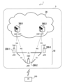
- FIG. 1 is a diagram showing a configuration of a mobile communication system 1 according to an embodiment.
- the mobile communication system 1 complies with the 3GPP standard 5th Generation System (5GS).
- 5GS is taken as an example, but the mobile communication system may be at least partially applied with an LTE (Long Term Evolution) system.
- LTE Long Term Evolution
- 6G 6th Generation
- the mobile communication system 1 has a user equipment (UE) 100, a 5G radio access network (NG-RAN: Next Generation Radio Access Network) 10, and a 5G core network (5GC: 5G Core Network) 20.
- NG-RAN Next Generation Radio Access Network
- 5GC 5G Core Network
- the NG-RAN 10 may be simply referred to as the RAN 10.
- the 5GC 20 may be simply referred to as the core network (CN) 20.
- the RAN 10 and the CN 20 constitute the network 5 of the mobile communication system 1.
- UE100 is a mobile wireless communication device.
- UE100 may be any device that is used by a user.
- UE100 is a mobile phone terminal (including a smartphone) and/or a tablet terminal, a notebook PC, a communication module (including a communication card or chipset), a sensor or a device provided in a sensor, a vehicle or a device provided in a vehicle (Vehicle UE), or an aircraft or a device provided in an aircraft (Aerial UE).
- NG-RAN10 includes base station (referred to as "gNB” in the 5G system) 200.
- gNB200 are connected to each other via an Xn interface, which is an interface between base stations.
- gNB200 manages one or more cells.
- gNB200 performs wireless communication with UE100 that has established a connection with its own cell.
- gNB200 has a radio resource management (RRM) function, a routing function for user data (hereinafter simply referred to as “data”), a measurement control function for mobility control and scheduling, etc.
- RRM radio resource management
- Cell is used as a term indicating the smallest unit of a wireless communication area.
- Cell is also used as a term indicating a function or resource for performing wireless communication with UE100.
- One cell belongs to one carrier frequency (hereinafter simply referred to as "frequency").
- gNBs can also be connected to the Evolved Packet Core (EPC), which is the core network of LTE.
- EPC Evolved Packet Core
- LTE base stations can also be connected to 5GC.
- LTE base stations and gNBs can also be connected via a base station-to-base station interface.
- 5GC20 includes AMF (Access and Mobility Management Function) and UPF (User Plane Function) 300.
- AMF performs various mobility controls for UE100.
- AMF manages the mobility of UE100 by communicating with UE100 using NAS (Non-Access Stratum) signaling.
- UPF controls data forwarding.
- AMF and UPF are connected to gNB200 via the NG interface, which is an interface between a base station and a core network.
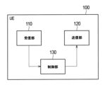
- FIG. 2 is a diagram showing the configuration of a UE 100 (user equipment) according to an embodiment.
- the UE 100 has a receiving unit 110, a transmitting unit 120, and a control unit 130.
- the receiving unit 110 and the transmitting unit 120 constitute a wireless communication unit that performs wireless communication with the gNB 200.
- the receiving unit 110 performs various types of reception under the control of the control unit 130.
- the receiving unit 110 includes an antenna and a receiver.
- the receiver converts the radio signal received by the antenna into a baseband signal (received signal) and outputs it to the control unit 130.
- the transmitting unit 120 performs various transmissions under the control of the control unit 130.
- the transmitting unit 120 includes an antenna and a transmitter.
- the transmitter converts the baseband signal (transmission signal) output by the control unit 130 into a radio signal and transmits it from the antenna.
- the control unit 130 performs various controls and processes in the UE 100. Such processes include the processes of each layer described below. The operations of the UE 100 described above and below may be operations under the control of the control unit 230.
- the control unit 130 includes at least one processor and at least one memory.
- the memory stores programs executed by the processor and information used in the processing by the processor.
- the processor may include a baseband processor and a CPU (Central Processing Unit).
- the baseband processor performs modulation/demodulation and encoding/decoding of baseband signals.
- the CPU executes programs stored in the memory to perform various processes.
- FIG. 3 is a diagram showing the configuration of a gNB 200 (base station) according to an embodiment.
- the gNB 200 has a transmitting unit 210, a receiving unit 220, a control unit 230, and a backhaul communication unit 240.
- the transmitting unit 210 and the receiving unit 220 constitute a wireless communication unit that performs wireless communication with the UE 100.
- the backhaul communication unit 240 constitutes a network communication unit that performs communication with the CN 20.
- the transmitting unit 210 performs various transmissions under the control of the control unit 230.
- the transmitting unit 210 includes an antenna and a transmitter.
- the transmitter converts the baseband signal (transmission signal) output by the control unit 230 into a radio signal and transmits it from the antenna.
- the receiving unit 220 performs various types of reception under the control of the control unit 230.
- the receiving unit 220 includes an antenna and a receiver.
- the receiver converts the radio signal received by the antenna into a baseband signal (received signal) and outputs it to the control unit 230.
- the control unit 230 performs various controls and processes in the gNB 200. Such processes include the processes of each layer described below.
- the operations of the gNB 200 described above and below may be operations under the control of the control unit 230.
- the control unit 230 includes at least one processor and at least one memory.
- the memory stores programs executed by the processor and information used in the processing by the processor.
- the processor may include a baseband processor and a CPU.
- the baseband processor performs modulation/demodulation and encoding/decoding of baseband signals.
- the CPU executes programs stored in the memory to perform various processes.
- the backhaul communication unit 240 is connected to adjacent base stations via an Xn interface, which is an interface between base stations.
- the backhaul communication unit 240 is connected to the AMF/UPF 300 via an NG interface, which is an interface between a base station and a core network.
- the gNB 200 may be composed of a CU (Central Unit) and a DU (Distributed Unit) (i.e., functionally divided), and the two units may be connected via an F1 interface, which is a fronthaul interface.
- Figure 4 shows the protocol stack configuration of the wireless interface of the user plane that handles data.
- the user plane radio interface protocol has a physical (PHY) layer, a medium access control (MAC) layer, a radio link control (RLC) layer, a packet data convergence protocol (PDCP) layer, and a service data adaptation protocol (SDAP) layer.
- PHY physical
- MAC medium access control
- RLC radio link control
- PDCP packet data convergence protocol
- SDAP service data adaptation protocol
- the PHY layer performs encoding/decoding, modulation/demodulation, antenna mapping/demapping, and resource mapping/demapping. Data and control information are transmitted between the PHY layer of UE100 and the PHY layer of gNB200 via a physical channel.
- the PHY layer of UE100 receives downlink control information (DCI) transmitted from gNB200 on a physical downlink control channel (PDCCH).
- DCI downlink control information
- PDCCH physical downlink control channel
- RNTI radio network temporary identifier
- the DCI transmitted from gNB200 has CRC parity bits scrambled by the RNTI added.
- the MAC layer performs data priority control, retransmission processing using Hybrid Automatic Repeat reQuest (HARQ), and random access procedures. Data and control information are transmitted between the MAC layer of UE100 and the MAC layer of gNB200 via a transport channel.
- the MAC layer of gNB200 includes a scheduler. The scheduler determines the uplink and downlink transport format (transport block size, modulation and coding scheme (MCS)) and the resource blocks to be assigned to UE100.
- MCS modulation and coding scheme
- the RLC layer uses the functions of the MAC layer and PHY layer to transmit data to the RLC layer on the receiving side. Data and control information are transmitted between the RLC layer of UE100 and the RLC layer of gNB200 via logical channels.
- the PDCP layer performs header compression/decompression, encryption/decryption, etc.
- the SDAP layer maps IP flows, which are the units for which the core network controls QoS (Quality of Service), to radio bearers, which are the units for which the AS (Access Stratum) controls QoS. Note that if the RAN is connected to the EPC, SDAP is not necessary.
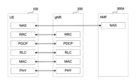
- Figure 5 shows the configuration of the protocol stack for the wireless interface of the control plane that handles signaling (control signals).
- the protocol stack of the radio interface of the control plane has an RRC (Radio Resource Control) layer and a NAS (Non-Access Stratum) layer instead of the SDAP layer shown in Figure 4.
- RRC Radio Resource Control
- NAS Non-Access Stratum
- RRC signaling for various settings is transmitted between the RRC layer of UE100 and the RRC layer of gNB200.
- the RRC layer controls logical channels, transport channels, and physical channels in response to the establishment, re-establishment, and release of radio bearers.
- RRC connection connection between the RRC of UE100 and the RRC of gNB200
- UE100 is in an RRC connected state.
- RRC connection no connection between the RRC of UE100 and the RRC of gNB200
- UE100 is in an RRC idle state.
- UE100 is in an RRC inactive state.
- the NAS layer (also simply referred to as "NAS") located above the RRC layer performs session management, mobility management, etc.
- NAS signaling is transmitted between the NAS layer of UE100 and the NAS layer of AMF300A.
- UE100 also has an application layer, etc.
- AS layer also simply referred to as "AS”
- the mobile communication system 1 can perform resource-efficient distribution by using a multicast/broadcast service (MBS).
- MBS multicast/broadcast service
- a session refers to a series of communications (from start to finish) of a service (application)
- an MBS session refers to a session used in MBS.
- a multicast communication service (also called "MBS multicast”)
- MBS multicast the same service and the same specific content data are provided simultaneously to a specific set of UEs. That is, not all UEs 100 in the multicast service area are allowed to receive the data.
- the multicast communication service is delivered to the UEs 100 using a multicast session, which is a type of MBS session.
- the UEs 100 can receive the multicast communication service in the RRC connected state using mechanisms such as PTP (Point-to-Point) and/or PTM (Point-to-Multipoint) delivery.
- the UEs 100 may receive the multicast communication service in the RRC inactive (or RRC idle) state.
- Such a delivery mode is also called "Delivery Mode 1".
- the UEs 100 can receive the multicast session only after joining the multicast session.
- joining a multicast session may mean being registered in the network 5 (CN 20) as a UE 100 capable of receiving the multicast session.
- broadcast communication service also referred to as "MBS broadcast”
- MBS broadcast the same service and the same specific content data are provided simultaneously to all UEs 100 in a geographical area. That is, all UEs 100 in the broadcast service area are allowed to receive the data.
- the broadcast communication service is delivered to the UEs 100 using a broadcast session, which is a type of MBS session.
- the UEs 100 can receive the broadcast communication service in any of the following states: RRC idle state, RRC inactive state, and RRC connected state.
- Such a delivery mode is also referred to as "delivery mode 2".
- the main logical channels used for MBS distribution are the Multicast Traffic Channel (MTCH), the Dedicated Traffic Channel (DTCH), and the Multicast Control Channel (MCCH).
- the MTCH is a PTM downlink channel for transmitting MBS data of either a multicast session or a broadcast session from the network 10 to the UE 100.
- the DTCH is a PTP channel for transmitting MBS data of a multicast session from the network 10 to the UE 100.
- the MCCH is a PTM downlink channel for transmitting MBS broadcast control information associated with one or more MTCHs from the network 10 to the UE 100.
- DCCH Dedicated Control Channel
- MBS packets can be either point-to-point (PTP) transmission, which is equivalent to unicast, or point-to-multipoint (PTM) transmission.
- PTP point-to-point
- PTM point-to-multipoint
- the gNB 200 can independently deliver individual copies of the MBS packet to each UE 100. For example, the gNB 200 schedules a UE-specific PDSCH scrambled with a UE-specific RNTI (e.g., C-RNTI) using a UE-specific PDCCH with a CRC (Cyclic Redundancy Code) scrambled with a UE-specific RNTI.
- a UE-specific RNTI e.g., C-RNTI
- CRC Cyclic Redundancy Code
- the gNB 200 delivers a single copy of the MBS packet to a set (group) of multiple UEs 100.
- gNB200 schedules a group-common PDSCH scrambled by a group-common RNTI using a group-common PDCCH having a CRC scrambled by a group-common RNTI (e.g., G-RNTI).
- UE100 in RRC idle state, RRC inactive state, or RRC connected state receives PTM settings for the broadcast session (e.g., parameters required for MTCH reception) via MCCH.
- the parameters required for MCCH reception (MCCH settings) are provided via system information.
- system information block type 20 SIB20
- SIB type 21 SIB21 includes information on service continuity for MBS broadcast reception.
- MCCH provides a list of all broadcast services including ongoing sessions transmitted on MTCH, and the related information for the broadcast session includes MBS session identifiers (e.g., TMGI (Temporary Mobile Group Identity)), related MTCH scheduling information, and information on neighboring cells providing a particular service on MTCH.
- MBS session identifiers e.g., TMGI (Temporary Mobile Group Identity)
- TMGI Temporal Mobile Group Identity
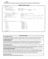
- FIG. 6 shows the MBS Broadcast Configuration message in the MCCH defined in the RRC technical specification (TS38.331).
- the MCCH includes an MBS Session Information List (mbs-SessionInfoList) that provides the configuration of each MBS session (each broadcast session) provided by MBS broadcast in the current cell, a list of neighboring cells that provide the MBS broadcast service via the broadcast MRB (mbs-NeighborCellList), a list of DRX settings (drx-ConfigPTM-List), and parameters for acquiring the PDSCH for the MTCH (pdsch-ConfigMTCH).
- mbs-SessionInfoList MBS Session Information List
- mbs-NeighborCellList a list of neighboring cells that provide the MBS broadcast service via the broadcast MRB
- drx-ConfigPTM-List a list of DRX settings
- pdsch-ConfigMTCH parameters for acquiring the PDSCH for the
- UE100 can only receive multicast session data in the RRC connected state.
- gNB200 sends an RRC Reconfiguration message to UE100, including PTM settings for the multicast session.
- PTM settings are also referred to as multicast radio bearer (MRB) settings, MTCH settings, or PTM settings.
- the MRB setting includes other parameters such as the MBS session identifier (mbs-SessionId), the MRB identifier (mrb-Identity), and the PDCP setting (pdcp-Config) for the MRB (multicast MRB) to be set in UE100.
- MBS session identifier mbs-SessionId
- MRB identifier mrb-Identity
- PDCP setting pdcp-Config
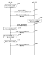
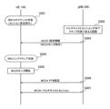
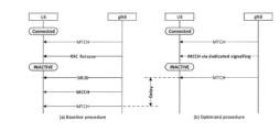
- Figure 7 shows an overview of the operation.
- Possible solutions for a UE 100 in an RRC inactive state to receive multicast include a distribution mode 1 based solution shown in FIG. 7(a) and a distribution mode 2 based solution shown in FIG. 7(b). Assume that the UE 100 supports multicast reception in an RRC inactive state and has already joined a multicast session.
- step S1 the gNB 200 sends an RRC Reconfiguration message including MBS settings (PTM settings) for the multicast session to the UE 100 in the RRC connected state.
- the UE 100 receives multicast data on the MTCH via the multicast session (multicast MRB) based on the PTM settings received in the RRC Reconfiguration message.
- step S2 gNB200 transmits an RRC Release message to UE100 in the RRC Connected state to transition UE100 to the RRC Inactive state.
- the RRC Release message includes a setting (Suspend Config.) for the RRC Inactive state.
- step S3 UE 100 transitions from the RRC connected state to the RRC inactive (INACTIVE) state in response to receiving the RRC Release message in step S2.
- step S4 UE 100 in the RRC inactive state continues to use the PTM settings of step S1 to receive multicast data on the MTCH via the multicast session.
- PTM configuration may also be performed using an RRC Release message.
- the RRC Reconfiguration message and the RRC Release message are both RRC messages transmitted individually to a UE on a dedicated control channel (DCCH), and are hereinafter also referred to as dedicated RRC messages or dedicated signaling.
- DCCH dedicated control channel
- step S11 the gNB 200 transmits an RRC Release message to the UE 100 in the RRC connected state to transition the UE 100 to the RRC inactive state.
- the RRC Release message includes a setting (Suspend Config.) for the RRC inactive state.
- step S12 UE 100 transitions to the RRC inactive (INACTIVE) state in response to receiving the RRC Release message in step S11.
- step S13 gNB200 transmits an MCCH including MBS settings (PTM settings) for the multicast session.
- UE100 receives the MCCH.
- UE100 receives SIB20 prior to receiving the MCCH, and receives the MCCH based on SIB20.
- MCCH transmission (and reception) may be performed prior to step S11, or may be performed simultaneously with step S11.
- step S14 UE 100 in the RRC inactive state receives multicast data on the MTCH via a multicast session based on the PTM setting received on the MCCH in step S13. This enables UE 100 in the RRC inactive state to perform multicast reception.
- a solution that combines a distribution mode 1-based solution and a distribution mode 2-based solution is also possible.
- a mixed setting method is possible in which the initial setting of the MBS setting (PTM setting) is performed by dedicated signaling, and the update of the MBS setting (PTM setting) is performed by MCCH.
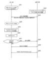
- FIG. 8 is a diagram for explaining an overview of the operation according to the first embodiment.
- Fig. 8(a) shows, as a comparative example, an example of a mixed setting method in which a solution based on distribution mode 1 and a solution based on distribution mode 2 are mixed.
- Fig. 8(b) shows an overview of the operation according to the first embodiment.
- step S51 UE 100 is in an RRC connected state.
- UE 100 supports multicast reception in an RRC inactive state and has already participated in a multicast session.
- step S52 gNB200 transmits an RRC Reconfiguration message including MBS settings (PTM settings) for the multicast session to UE100 in the RRC connected state on the DCCH.
- UE100 receives the RRC Reconfiguration message and establishes a multicast MRB. At this point, the multicast session becomes activated.
- MBS settings PTM settings
- step S53 gNB200 transmits the multicast session on the MTCH.
- UE100 receives the multicast session on the MTCH via the multicast MRB based on the PTM setting received in the RRC Reconfiguration message in step S52.
- step S54 gNB200 transmits an RRC Release message to UE100 in the RRC connected state to transition UE100 to the RRC inactive state.
- step S55 UE 100 transitions to the RRC inactive (INACTIVE) state in response to receiving the RRC Release message in step S54.
- step S56 gNB200 transmits SIB20 including the MCCH setting on BCCH.
- UE100 in the RRC inactive state receives SIB20.
- gNB200 transmits PTM configuration (e.g., MBSBroadcastConfiguration message) for the multicast session on the MCCH.
- PTM configuration e.g., MBSBroadcastConfiguration message
- UE100 in the RRC inactive state receives the PTM configuration on the MCCH based on SIB20 in step S56.
- UE100 establishes a new MRB according to the PTM configuration.
- the new MRB may be a broadcast MRB.
- step S58 gNB200 transmits the multicast session on MTCH via the new MRB.
- UE100 in the RRC inactive state receives the multicast session on MTCH.
- the gNB 200 transmits a PTM setting for the multicast session on the DCCH to the UE 100 that is in the RRC connected state and has already participated in the multicast session (step S104).
- the gNB 200 transmits a PTM setting on the DCCH that includes the same information element as the information element provided on the MCCH.
- the UE 100 that is in the RRC connected state and has already participated in the multicast session receives the PTM setting on the DCCH (step S104).
- the UE 100 can quickly receive the multicast session on the MTCH (step S106) after transitioning to the RRC inactive state (step S105).
- step S101 UE 100 is in an RRC connected state.
- UE 100 supports multicast reception in an RRC inactive state, and has already participated in a multicast session.
- step S102 gNB200 transmits an RRC Reconfiguration message including MBS settings (PTM settings) for the multicast session to UE100 in the RRC connected state on the DCCH.
- UE100 receives the RRC Reconfiguration message and establishes a multicast MRB (first MRB). At this point, the multicast session is in an activated state.
- MBS settings PTM settings
- step S103 gNB200 transmits the multicast session on the MTCH.
- UE100 receives the multicast session on the MTCH via the multicast MRB based on the PTM setting received in the RRC Reconfiguration message in step S102.
- gNB200 transmits a PTM setting similar to the PTM setting (e.g., MBSBroadcastConfiguration message) transmitted on the MCCH to UE100 in the RRC connected state on the DCCH (i.e., dedicated signaling). For example, gNB200 transmits an RRC Reconfiguration message including the PTM setting or an RRC Release message including the PTM setting.
- UE100 in the RRC connected state receives the PTM setting on the DCCH.
- UE100 recognizes the received PTM setting as setting information for multicast reception.
- UE100 establishes a new MRB (second MRB) according to the PTM setting.
- the new MRB may be a broadcast MRB.
- step S105 UE100 transitions to the RRC inactive state. If step S104 is performed with an RRC Reconfiguration message, gNB200 transmits an RRC Release message to transition UE100 to the RRC inactive state. UE100 transitions to the RRC inactive state in response to receiving the RRC Release message.
- step S106 the gNB 200 transmits the multicast session on the MTCH via the new MRB (second MRB).
- the UE 100 in the RRC inactive state receives the multicast session on the MTCH.
- the UE 100 may perform a predetermined process for switching from the first MRB to the second MRB depending on the result of comparing the sequence number of the MBS packet received via the first MRB for the RRC connected state with the sequence number of the MBS packet received via the second MRB for the RRC inactive state. This makes it easier to achieve consistency of received packets between the first MRB and the second MRB.
- step S104 is performed by an RRC Reconfiguration message.
- the specified process may be a process of transmitting a notification for the switching (e.g., a consistency notification) to the gNB200.
- step S104 is performed by an RRC Release message.
- the specified process may be a process of transitioning from an RRC connected state to an RRC inactive state.
- FIG. 9 is a diagram showing an example of the first operation pattern of the first embodiment. Here, a description of operations that overlap with the operations shown in FIG. 8(b) will be omitted.
- step S111 UE 100 in the RRC connected state participates in the multicast session.
- step S112 gNB200 sends a multicast MRB setting (PTM setting) to UE100 in an RRC Reconfiguration message.
- UE100 receives the PTM setting and establishes a multicast MRB (first MRB).
- the multicast session becomes activated.
- step S113 UE 100 in the RRC connected state receives a multicast session from gNB 200 on MTCH via the first MRB.
- step S114 gNB200 decides to have UE100 perform multicast reception in the RRC inactive state.
- step S115 gNB200 transmits the PTM settings (setting information such as MTCH scheduling) of the multicast session to UE100 via DCCH.
- the message transmitted on DCCH in step S115 is an RRC Reconfiguration message.
- UE100 receives the PTM settings and establishes a second MRB.
- the second MRB may be 1) a multicast MRB, 2) a broadcast MRB for multicast, or 3) a new type of MRB for multicast reception in an RRC inactive state.
- UE100 associates the originally configured multicast MRB (first MRB) with the newly configured MRB for an RRC inactive state (second MRB).
- the PTM setting in step S115 may be the same PTM setting as the MBS broadcast setting provided on the MCCH.
- the PTM setting in step S115 is new information used for multicast reception in the RRC inactive state, and may include the same information elements as the MBS broadcast setting provided on the MCCH.
- the PTM setting in step S115 may include only the PTM setting of the multicast session that UE100 is receiving. That is, the PTM setting in step S115 may include only the PTM setting of the activated multicast session. Alternatively, the PTM setting in step S115 may include only the PTM setting of the MBS session in which the multicast MRB is set in UE100. The PTM setting in step S115 may not include the PTM setting of the broadcast session. Alternatively, the PTM setting in step S115 may include only the PTM setting of the multicast session in which UE100 has joined. That is, the PTM setting in step S115 may include only the PTM setting of the multicast session that can be activated.
- step S116 UE100 recognizes that the PTM setting received from gNB200 via DCCH is related to a multicast session.
- UE100 may perform this recognition when it receives a PTM setting that does not include an MRB setting (MRB-ToAddMod).
- UE100 may perform this recognition when it receives a PTM setting that does not include an MRB identifier (MRB-Identity).
- MRB-Identity MRB identifier
- UE100 may recognize that the PTM setting is a setting to be used for reception in an RRC inactive state. However, UE100 may perform multicast reception using the setting while remaining in an RRC connected state.
- step S117 UE 100 in the RRC connected state receives a multicast session from gNB 200 on the MTCH via the second MRB based on the PTM setting in step S115.
- step S118 the UE 100 in the RRC connected state compares the sequence number (SN) of the received packet in the first MRB with the SN of the received packet in the second MRB. For example, the UE 100 compares the PDCP SN of the received PDCP packet in the first MRB with the PDCP SN of the received PDCP packet in the second MRB. The UE 100 may determine that there are no unreceived packets if there is no gap between the SN of the last packet received in the first MRB and the SN of the first packet received in the second MRB.
- the UE 100 may determine that there are no unreceived packets if the difference between the SN of the last packet received in the first MRB and the SN of the first packet received in the second MRB is equal to or less than a threshold.
- the threshold may be set in the UE 100 by the gNB 200.
- UE100 in the RRC connected state transmits a notification to gNB200 indicating that switching from the first MRB to the second MRB is possible or that the switching has been completed.
- UE100 may transmit the notification to gNB200 by including it in a response message (e.g., an RRC Reconfiguration Complete message) corresponding to the RRC Reconfiguration message of step S115.
- UE100 may transmit the notification in a UE Assistance Information message.
- UE100 may transmit it as part of Release Assistance Information (specifically, the "ReleasePreference" IE), which is an information element included in the UE Assistance Information message.
- step S120 based on the notification in step S119, gNB200 transmits an RRC Release message to UE100 to transition UE100 to the RRC inactive state.
- step S121 UE100 transitions to the RRC inactive state in response to receiving the RRC Release message.
- step S122 UE 100 in the RRC connected state receives a multicast session from gNB 200 on the MTCH via the second MRB based on the PTM setting in step S115.
- FIG. 10 is a diagram showing an example of the second operation pattern of the first embodiment. Here, a description of operations that overlap with the first operation pattern of FIG. 9 will be omitted.
- steps S131 to S134 are similar to those in steps S111 to S114 in FIG. 9.
- step S135 gNB200 transmits the PTM settings of the multicast session (setting information such as MTCH scheduling) to UE100 via DCCH.
- the message transmitted on DCCH in step S135 is an RRC Release message.
- UE100 receives the PTM settings and establishes a second MRB.
- the second MRB may be 1) a multicast MRB, 2) a broadcast MRB for multicast, or 3) a new type of MRB for multicast reception in an RRC inactive state.
- UE100 associates the originally configured multicast MRB (first MRB) with the newly configured MRB for an RRC inactive state (second MRB).
- the PTM setting in step S135 may be the same PTM setting as the MBS broadcast setting provided on the MCCH.
- the PTM setting in step S135 is new information used for multicast reception in the RRC inactive state, and may include the same information elements as the MBS broadcast setting provided on the MCCH.
- the PTM settings in step S135 may include only the PTM settings of the multicast session that UE100 is receiving. That is, the PTM settings in step S135 may include only the PTM settings of the activated multicast session. Alternatively, the PTM settings in step S135 may include only the PTM settings of the MBS session in which the multicast MRB is set in UE100. The PTM settings in step S135 may not include the PTM settings of the broadcast session.
- step S136 UE100 recognizes that the PTM setting received from gNB200 via DCCH is related to a multicast session.
- UE100 may recognize that the PTM setting is a setting to be used for reception in an RRC inactive state. However, UE100 may perform multicast reception using the setting while remaining in an RRC connected state.
- step S137 UE 100 in the RRC connected state receives a multicast session from gNB 200 on the MTCH via the second MRB based on the PTM setting in step S135. At this point, UE 100 that has received the RRC Release message suspends transition to the RRC inactive state.
- step S138 the UE 100 in the RRC connected state compares the sequence number (SN) of the received packet in the first MRB with the SN of the received packet in the second MRB. For example, the UE 100 compares the PDCP SN of the received PDCP packet in the first MRB with the PDCP SN of the received PDCP packet in the second MRB. The UE 100 may determine that there are no unreceived packets if there is no gap between the SN of the last packet received in the first MRB and the SN of the first packet received in the second MRB.
- the UE 100 may determine that there are no unreceived packets if the difference between the SN of the last packet received in the first MRB and the SN of the first packet received in the second MRB is equal to or less than a threshold.
- the threshold may be set in the UE 100 by the gNB 200.
- step S139 UE 100 in the RRC connected state transitions to the RRC inactive state.
- step S140 UE 100 in the RRC connected state receives a multicast session from gNB 200 on the MTCH via the second MRB based on the PTM setting in step S135.
- Second embodiment A second embodiment will be described, focusing mainly on the differences from the first embodiment, with reference to Fig. 11 and Fig. 12. Note that the second embodiment may be implemented in combination with the first embodiment.
- gNB 200 when a multicast session has not yet been activated, gNB 200 provides UE 100 with configuration information related to the RRC inactive state via DCCH (dedicated signaling). Specifically, gNB 200 configures information related to permission for multicast reception in the RRC inactive state for UE 100 in the RRC connected state via dedicated signaling for a multicast session in the inactive state (before activation).
- DCCH dedicated signaling
- UE100 which is in an RRC connected state and has already participated in a multicast session, receives configuration information from gNB200 on DCCH.
- UE100 receives configuration information regarding permission to receive multicast in an RRC inactive state from gNB200 on DCCH.
- the setting information includes an information element that instructs monitoring the MCCH (obtaining the PTM setting from the MCCH).
- the information element may be an information element that instructs monitoring the MCCH after transitioning to the RRC inactive state.
- the UE 100 monitors the MCCH based on the information element.
- the setting information may include an information element that permits a request for an MCCH when the serving cell is not transmitting an MCCH.
- the information element may be an information element that permits a request for an MCCH when the current serving cell is not transmitting an MCCH after transition to the RRC inactive state and when the multicast session is activated.
- the configuration information may include an information element that prohibits UE 100 from transitioning to the RRC connected state in response to receiving a paging message indicating activation of a multicast session. Even if UE 100 receives a paging message indicating activation of a multicast session from gNB 200, UE 100 maintains the RRC inactive state without transitioning to the RRC connected state.
- FIG. 11 is a diagram showing an example of the first operation pattern of the second embodiment.
- step S201 UE 100 in the RRC connected state participates in a multicast session.
- step S202 gNB200 recognizes that the multicast session has not yet been activated (i.e., is in an inactive state). In addition, gNB200 can recognize whether the multicast session has been activated or not based on a message (e.g., a "MULTICAST SESSION ACTIVATION REQUEST" message) received on the NG interface from CN20 (AMF300A).
- a message e.g., a "MULTICAST SESSION ACTIVATION REQUEST" message
- step S203 gNB200 transmits configuration information regarding multicast reception in the RRC inactive state to UE100 in the RRC connected state on the DCCH (i.e., by dedicated signaling).
- UE100 receives the configuration information on the DCCH.
- the dedicated signaling may be an RRC Reconfiguration message or an RRC Release message.
- the configuration information of step S203 may include an information element that instructs UE100 to monitor the MCCH (even in the RRC connected state).
- the configuration information of step S203 may include an information element that instructs UE100 to monitor the MCCH when UE100 transitions to the RRC inactive state.
- the configuration information of step S203 may include an MBS session ID (e.g., TMGI) of a multicast session for which PTM settings should be obtained from the MCCH.
- UE100 may notify gNB200 when it successfully receives MCCH (in the RRC connected state) (or when it successfully establishes an MRB).
- UE100 may send the notification in a UE Assistance Information message. For example, it may be transmitted as part of Release Assistance Information (specifically, the "ReleasePreference" IE), which is an information element included in UE Assistance Information.
- UE 100 may notify gNB 200 when MCCH reception fails.
- the configuration information of step S203 may include an information element that instructs UE100 not to monitor group paging (i.e., a paging message including the MBS session ID of the multicast session to be activated) in the RRC inactive state, or to ignore the MBS session ID in the paging message.
- group paging i.e., a paging message including the MBS session ID of the multicast session to be activated
- UE100 is prevented from transitioning to the RRC connected state in response to receiving group paging, and it becomes easier for UE100 to continue multicast reception in the RRC inactive state.
- UE100 can be controlled not to transition to the RRC connected state.
- step S204 UE100 may transition to the RRC inactive state. If step S203 is performed with an RRC Reconfiguration message, gNB200 may transmit an RRC Release message to transition UE100 to the RRC inactive state. UE100 may transition to the RRC inactive state in response to receiving the RRC Release message.
- step S205 UE 100 in the RRC inactive state or the RRC connected state starts monitoring the MCCH based on the configuration information in step S203.
- step S206 gNB200 transmits (broadcasts) the PTM settings for the multicast session on the MCCH.
- gNB200 recognizes that the multicast session has been activated, and may transmit (broadcast) the PTM settings for the activated multicast session on the MCCH.
- UE100 receives the PTM settings on the MCCH.
- step S207 gNB200 transmits (multicasts) the multicast session on MTCH.
- UE100 receives the multicast session on MTCH based on the PTM setting in step S206.
- FIG. 12 is a diagram showing an example of the second operation pattern of the second embodiment. Here, a description of operations that overlap with the first operation pattern shown in FIG. 11 will be omitted. Note that this second operation pattern may be implemented in combination with the first operation pattern shown in FIG. 11.
- step S231 UE100 is in an RRC connected state and has already participated in the multicast session.
- step S232 gNB200 recognizes that the multicast session has not yet been activated (i.e., is in an inactive state).
- step S233 gNB200 transmits configuration information regarding multicast reception in RRC inactive state to UE100 in RRC connected state on DCCH.
- UE100 receives the configuration information on DCCH.
- the configuration information may include an information element that instructs UE100 to obtain PTM settings from MCCH.
- the configuration information may include an information element that permits UE100 to make a request for MCCH.
- gNB200 may transition UE100 to an RRC inactive state by an RRC Release message.
- UE100 that has transitioned to the RRC inactive state may reselect a cell other than the cell in which the setting in step S233 was performed.
- UE100 in the RRC inactive state or the RRC connected state recognizes the activation timing, which is the timing at which the multicast session is started (activated).
- the activation timing may be the timing at which UE100 receives a group paging including the MBS session ID of the multicast session from gNB200.
- the activation timing may be the timing at which UE100 receives an MCCH Change Notification from gNB200 and the PTM setting of the multicast session is added.
- the activation timing may be the timing at which the start time of the multicast session is reached based on USD (User Service Description) information previously held by UE100.
- USD User Service Description
- step S236 UE 100 in the RRC inactive state or the RRC connected state starts monitoring the MCCH in response to recognizing the activation timing.
- step S2308 UE100 in the RRC inactive state or the RRC connected state transmits an MCCH request to gNB200.
- UE100 may transmit the MCCH request in Msg1, Msg3, or Msg5 of the random access procedure.
- UE100 may transmit the MCCH request in an MBS Interest Indication message or a UE Assistance information message.
- gNB200 transmits the PTM setting of the multicast session on the MCCH.
- gNB200 may start broadcasting the MCCH.
- gNB200 may transmit the MCCH contents (PTM setting) to UE100 in the RRC connected state in an RRC Reconfiguration message.
- gNB200 may transmit the MCCH contents (PTM setting) to UE100 in an RRC Release message.
- UE100 may request the MCCH contents (PTM setting) from gNB200 in Msg3 (RRC Resume message) of the random access procedure, and in response to the Msg3, gNB200 may transmit the MCCH contents (PTM setting) to UE100 in an RRC Release message.
- Msg3 RRC Resume message
- step S240 gNB200 transmits (multicasts) the multicast session on the MTCH.
- UE100 receives the multicast session on the MTCH based on the PTM setting in step S239.
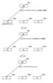
- FIG. 13 is a diagram for explaining an example of operation when the distribution mode 2 is applied to the MBS multicast.
- the gNB 200 transmits the SIB 20 including the MCCH setting (specifically, the scheduling information of the MCCH, etc.) to the UE 100 (UEs 100a to 100c in the illustrated example) on the broadcast control channel (BCCH).
- FIG. 14 shows the configuration of the SIB 20 specified in the RRC specification (TS38.331) of 3GPP Release 17.
- the SIB 20 includes the mcch-Config-r17, which is the MCCH setting.
- the PTM setting (MTCH setting) is transmitted on the MCCH from the gNB 200 to the UE 100.
- the multicast session (specifically, multicast PTM data) is transmitted on the MTCH from the gNB 200 to the UE 100.
- SIB20 transmission and MCCH transmission are performed by broadcast, all UEs 100 in the cell to which SIB20 and MCCH are transmitted can receive the multicast session.
- MBS multicast should only be received by a specific set of UEs participating in the multicast session. Therefore, there is a security concern if the multicast PTM settings (i.e., MCCH) are available to all UEs 100.
- an operation (communication method) capable of performing appropriate multicast distribution using MCCH will be described.
- FIG. 15 is a diagram for explaining the operation (communication method) of a mobile communication system 1 according to another embodiment.
- the gNB 200 transmits, to the UE 100 (UE 100a in the illustrated example) in an RRC connected state, scheduling information of the MCCH (MCCH setting) that transmits the PTM setting of the multicast session by dedicated signaling (e.g., DCCH).
- the UE 100 receives the MCCH scheduling information (MCCH setting).
- the MCCH scheduling information (MCCH setting) is scheduling information of the MCCH for the multicast session that transmits the PTM setting of the multicast session.
- the MCCH for the multicast session is an MCCH different from the MCCH for the broadcast session that transmits the PTM setting of the broadcast session.
- gNB200 transmits an MCCH for a multicast session.
- gNB200 may transmit the MCCH for a multicast session with a different scheduling (e.g., time/frequency resources) than the MCCH for a broadcast session.
- UE100 (UE100a in the illustrated example) receives the MCCH for the multicast session.
- UE100 may be in an RRC connected state, an RRC inactive state, or an RRC idle state.
- gNB200 transmits a multicast session (multicast MBS data) on MTCH.
- UE100 receives the multicast session.
- UE100 may be in an RRC connected state, an RRC inactive state, or an RRC idle state.
- the MCCH configuration for the MCCH for the multicast session is provided to the UEs 100 by dedicated signaling. This allows the MCCH configuration for the multicast session to be provided only to a specific UE 100 (or a specific set of UEs 100). Therefore, even when an MCCH is used, it becomes easy for only a specific UE 100 (or a specific set of UEs 100) participating in a multicast session to receive the multicast session.
- multicast reception in the RRC inactive state has been mainly described, but the operation according to the above embodiment may be applied to multicast reception in the RRC idle state.
- the above-mentioned RRC resume is replaced with RRC establishment.
- Each of the above-mentioned operation flows can be implemented not only separately but also by combining two or more operation flows. For example, some steps of one operation flow can be added to another operation flow, or some steps of one operation flow can be replaced with some steps of another operation flow. In each flow, it is not necessary to execute all steps, and only some of the steps can be executed.
- the base station is an NR base station (gNB)
- the base station may be an LTE base station (eNB) or a 6G base station.
- the base station may also be a relay node such as an IAB (Integrated Access and Backhaul) node.
- the base station may be a DU of an IAB node.
- the UE 100 may also be an MT (Mobile Termination) of an IAB node.
- network node primarily refers to a base station, but may also refer to a core network device or part of a base station (CU, DU, or RU).
- a network node may also be composed of a combination of at least part of a core network device and at least part of a base station.
- a program may be provided that causes a computer to execute each process performed by the UE100, the gNB200, or the relay device.
- the program may be recorded in a computer-readable medium.
- the computer-readable medium on which the program is recorded may be a non-transient recording medium.
- the non-transient recording medium is not particularly limited, and may be, for example, a recording medium such as a CD-ROM or a DVD-ROM.
- a circuit that executes each process performed by the UE100, the gNB200, or the relay device may be integrated, and at least a part of the UE100, the gNB200, or the relay device may be configured as a semiconductor integrated circuit (chip set, SoC: System on a chip).
- UE100, gNB200 network node
- relay device may be implemented in circuitry or processing circuitry, including general-purpose processors, application-specific processors, integrated circuits, ASICs (Application Specific Integrated Circuits), CPUs (Central Processing Units), conventional circuits, and/or combinations thereof, programmed to realize the described functions.
- Processors include transistors and other circuits and are considered to be circuitry or processing circuitry.
- Processors may be programmed processors that execute programs stored in memory.
- circuitry, units, and means are hardware that is programmed to realize the described functions or hardware that executes them.
- the hardware may be any hardware disclosed herein or any hardware known to be programmed or capable of performing the described functions. If the hardware is a processor considered to be a type of circuitry, the circuitry, means, or unit is a combination of hardware and software used to configure the hardware and/or processor.
- the terms “based on” and “depending on/in response to” do not mean “based only on” or “only in response to” unless otherwise specified.
- the term “based on” means both “based only on” and “based at least in part on”.
- the term “in response to” means both “only in response to” and “at least in part on”.
- the terms “include”, “comprise”, and variations thereof do not mean including only the recited items, but may include only the recited items or may include additional items in addition to the recited items.
- the term “or” as used in this disclosure is not intended to mean an exclusive or.
- a communication method for use in a mobile communication system providing a multicast/broadcast service comprising: A method comprising: a user equipment, which is in a Radio Resource Control (RRC) connected state and has joined a multicast session, receiving a point-to-multipoint (PTM) configuration for the multicast session from a base station on a dedicated control channel (DCCH); The receiving step includes receiving the PTM configuration from the base station on the DCCH including information elements that are the same as information elements provided on a multicast control channel (MCCH) if the multicast session is activated.
- RRC Radio Resource Control
- DCCH dedicated control channel
- the step of receiving the PTM configuration includes the step of receiving an RRC reconfiguration message including the PTM configuration;
- the communication method according to claim 3, wherein the step of performing the predetermined process includes a step of transmitting a notification for the switching to the base station.
- the step of receiving the PTM configuration includes the step of receiving an RRC release message including the PTM configuration;
- the communication method according to claim 3, wherein the step of performing the predetermined process includes a step of transitioning from the RRC connected state to the RRC inactive state.
- a communication method for use in a mobile communication system providing a multicast/broadcast service comprising: A method comprising: a user equipment in a Radio Resource Control (RRC) connected state and having joined a multicast session receiving configuration information from a base station on a Dedicated Control Channel (DCCH); The communication method, wherein the receiving step includes a step of receiving, from the base station, configuration information regarding permission of multicast reception in an RRC inactive state if the multicast session has not yet been activated.
- RRC Radio Resource Control
- the setting information includes an information element instructing monitoring of a multicast control channel (MCCH), The communication method of claim 6, further comprising the step of the user equipment monitoring the MCCH based on the information element.
- MCCH multicast control channel
- the configuration information includes an information element that allows the user equipment to request the base station to provide a multicast control channel (MCCH); the user equipment detecting activation of the multicast session;
- PTM Configuration Distribution Rel-17 specifies two distribution modes: a mode called “distribution mode 1" for multicast sessions and a mode called “distribution mode 2" for broadcast sessions.
- MTCH reception configuration is performed by RRC reconfiguration only for UEs in the connected state
- MTCH reception configuration is performed by MCCH for UEs in all RRC states.
- RAN2#119e specifies these delivery modes, namely option 1, option 2, and a "mix" of these options, as candidates for inactive multicast reception.
- RAN2 For distribution of PTM settings, RAN2 is further considering the following solutions: Option 1: Dedicated signalling Option 2: Solution based on SIB+MCCH A "mix" of options is not excluded.
- RAN2#120 has reached a consensus to move forward with a "mixed approach.”
- We have a mixed approach starting as follows: 1.
- the NW configures a UE to continue multicast reception in an inactive state, the NW provides PTM configuration for an activated multicast session via RRC dedicated signaling at least for the serving cell (other cases require further consideration).
- MCCH is used when PTM settings need to be changed or when PTM settings need to be indicated during transition across serving cells/gNBs. Session state changes and other indications require further study. 3. It is assumed that a UE can receive a multicast service after joining the session. 4. Whether the MCCH configuration is initially provided to the UE via dedicated signaling needs further study.
- the network sets the PTM configuration of the activated multicast session to the UE via dedicated signaling. Since the multicast session is activated, it is assumed that the connected UE is already receiving the multicast session and that this PTM configuration allows the UE to continue receiving the multicast session even after the UE transitions to inactive.
- the "mixed approach" agreed upon by RAN2 means using MCCH for updating PTM settings, etc., and is therefore closer to Rel-17's delivery mode 2.
- dedicated signaling only provides MCCH content (e.g., MBS Broadcast Configuration) rather than Rel-17-specific multicast settings (e.g., mrb-ToAddModList).
- Such dedicated signaling is useful for avoiding UEs monitoring MCCH while connected, and for minimizing service interruptions due to delays in acquiring MCCH after transitioning to inactive.
- Proposal 1 RAN2 should agree to provide MCCH content for multicast reception when dedicated signaling is inactive (i.e., MBS Broadcast Configuration).
- RAN2 has agreed that an inactive UE can start receiving a multicast session, i.e., Scenario 2 of the agreement below, so it is unclear what can be configured for a deactivated multicast session.
- multicast reception for an inactive UE supports at least the following scenarios, assuming the UE already has a valid PTM configuration: - Scenario 1: The UE is connected and receiving multicast, goes inactive and continues receiving multicast. - Scenario 2: A UE joins a multicast session and is induced to become inactive; the UE starts receiving the multicast session. Further consideration is required regarding state changes, such as state changes due to services not being provided in the inactive state.
- Actual PTM settings may not be provided for an inactivated multicast session, but may be provided once the multicast session is activated.
- an inactive UE transitions to connected upon receiving a group paging for multicast session activation.
- some kind of indication may be provided via dedicated signaling in advance to allow the UE to remain inactive and use the PTM settings obtained from the MCCH for the multicast session.
- Another approach is for such an indication to be provided by group paging as discussed in the following section.
- Proposal 2 RAN2 should discuss whether any configuration can be provided via dedicated signaling if the UE transitions to inactive before the multicast session is activated.
- MCCH is used when PTM settings need to be changed or when PTM settings need to be indicated during transition across serving cells/gNBs. Session status changes and other indications are a bit ambiguous, i.e. whether MCCH is used for indication or to provide PTM settings. If it was only indication, it could mean MCCH Change Notification. But MCCH provides PTM settings, e.g. updating PTM setting configuration of inactive UEs.
- Proposal 3 RAN2 should clarify whether MCCH provides PTM configuration for multicast sessions of inactive UEs, e.g. when PTM configuration is updated.
- RAN2 leaves the question of whether the MCCH configuration is initially provided to the UE via dedicated signaling.
- MCCH configuration means SIB20.
- SIB20 As RAN2 agreed, since dedicated signaling is inactive and provides PTM configuration for multicast reception, the UE does not need to read the MCCH immediately, and the UE does not need to know what SIB20, i.e. the MCCH configuration, is. Of course, the UE will get SIB20 and MCCH later and check whether the PTM configuration has been updated.
- Proposal 4 RAN2 should agree that MCCH configuration (i.e., SIB20) does not need to be provided via dedicated signaling.
- MCCH Mobility and Service Continuity RAN2#120 agreed that MCCH will be used during UE transition.
- This disclosure has a mixed approach and begins as follows. 1. If the NW configures the UE to continue multicast reception in an inactive state, the NW provides the PTM configuration of the activated multicast session via RRC dedicated signaling at least for the serving cell (other cases require further consideration). 2. MCCH is used when the PTM setting needs to be changed or when the PTM setting needs to be indicated during transition across serving cells/gNBs. Session state changes and other indications require further study. 3. It is assumed that a UE can receive a multicast service after joining the session. 4. Whether the MCCH configuration is initially provided to the UE via dedicated signaling needs further study.
- WID states that seamless/lossless mobility is not required. Specifies support for multicast reception by UEs in RRC inactive state [RAN2, RAN3] PTM configuration for UE receiving multicast in RRC inactive state [RAN2] Investigating the impact of mobility and state transitions for UEs receiving multicast in RRC inactive (seamless/lossless mobility is not mandatory) [RAN2, RAN3]
- the new PTM configuration delivery method is similar to Rel-17 delivery mode 2. Therefore, it is natural to base the service continuity mechanism of Rel-17 MBS broadcast on it. In this case, the multicast session must first ensure that neighbor cell information is provided by the MCCH to allow UEs to prioritize MBS frequencies during cell reselection.
- LTE SC-PTM and NR MBS Broadcast it is up to the UE implementation to determine how to ensure service continuity. For example, how to use neighboring cell information, whether to prioritize MBS frequencies, and how/when to acquire MCCH from neighboring cells are all up to the UE implementation.
- Proposal 5 RAN2 should agree that neighbor cell information for multicast sessions will be provided by MCCH, similar to MBS broadcast.
- Proposal 6 RAN2 should agree that UEs are allowed to prioritize MBS multicast frequencies during cell reselection, similar to MBS broadcast.
- PTM settings in multiple cells can improve service continuity during UE transitions.
- Intra-gNB PTM settings in each cell can be easily aligned (if necessary), but inter-gNB is difficult and requires negotiation involving Xn-AP.
- RAN2 needs to discuss whether PTM settings can be applied to multiple cells in a gNB.
- Proposal 7 RAN2 should consider whether PTM configuration can be applied to multiple cells within a gNB.
- the intra-gNB scenario is the basic assumption.
- WID says that seamless/lossless mobility is not required, it does not mean that all multicast sessions that the UE can receive inactively do not require seamless/lossless mobility. For example, due to congestion, the network needs to transition the UE to inactive, but due to QoS requirements, the UE needs to transition after it is connected.
- Rel-17 MBS multicast supports handover in RRC connection. Therefore, the network may need an option to control whether the UE should perform cell reselection or resume RRC connection before cell reselection (in case of handover in connected).
- Proposal 8 RAN2 should discuss whether gNB can indicate whether UE is allowed to perform inactive mode mobility or should resume RRC connection before cell reselection for better QoS control.
- eMBS enhanced MBS
- RAN2 Identifying support for multicast reception by UEs in RRC inactive state [RAN2, AN3] PTM configuration for UEs receiving multicast in RRC inactive state [RAN2] Study the impact of mobility and state transitions for UEs receiving multicast in RRC inactive (seamless/lossless mobility is not mandatory) [RAN2, RAN3]
- notification and RRC state transition behavior for multicast reception in inactive mode is discussed in this appendix.
- the multicast session is considered to be inactivated or released. In this case, there is no reason for the UE to continue monitoring the MTCH, but it shall do so unless the PTM configuration is removed. From a UE power saving point of view, it is desirable to stop monitoring MTCH as soon as possible.
- the UE should be allowed to stop monitoring MTCH when it receives a notification for multicast session deactivation, regardless of how it is notified. Also, the UE should remain in RRC inactive when such a notification is received.
- Proposal 1 RAN2 should agree that upon receiving a multicast session release notification, the UE is allowed to stop the monitor MTCH.
- RAN2 has stated that further consideration is required regarding the method of notifying UEs, such as group paging, MCCH, or other methods.
- the SC-PTM Stop Indication MAC CE is introduced to inform the UE to stop monitoring the PDCCH of the G-RNTI, and the MAC CE is multiplexed onto the SC-MTCH associated with the G-RNTI.
- This lightweight signaling may work under the constraint of one-to-one mapping between TMGI and G-RNTI.
- NR MBS allows many-to-one mapping between TMGI and G-RNTI, so when the MAC CE is introduced, it is necessary to indicate the inactivated TMGI. Since the MAC CE is sent together with the MTCH, it is expected to minimize the delay between receiving the last multicast data and stopping monitoring the MTCH.
- Group paging is used to page multiple UEs in a group simultaneously using TMGI instead of UE-ID. Since the existing paging group list (i.e. list of TMGI) can also be applied to legacy UEs, group paging requires adding a new TMGI list for invalidation notification to avoid impacting legacy UEs. This means that there is a delay between receiving the last multicast data and stopping MTCH monitoring based on the I-DRX period.
- the third option is to reuse the MCCH.
- the MCCH needs to be updated, so an MCCH change notification needs to be sent to the UE in advance. This requires a longer delay between the reception of the last multicast data and the stopping of MTCH monitoring.
- any delay between receiving the last multicast data and stopping MTCH monitoring can directly impact unnecessary UE power consumption increase. From a UE power saving point of view, notifications need to be sent as soon as possible, so the first option using MAC CE is the preferred solution.
- Proposal 2 RAN2 should agree that when a multicast session becomes inactive, a new MAC CE (similar to the existing SC-PTM Stop Indication) is notified to inactive UEs.
- the Rel-17 NAS-based indication agreed by RAN2 applies, which may be "Multicast session release requested by network or MBS session release".
- This procedure assumes that the UE is paged by the gNB and transitions to RRC connected to communicate with the AMF.
- This procedure assumes that existing group paging (or conventional individual paging) can be reused.
- a new MAC CE is introduced for multicast session invalidation notification as in Proposal 2
- this procedure can be used for free. That is, the gNB sends a MAC CE to allow the UE to stop monitoring the MTCH, and then the gNB can distribute the timing of pages to the UE, i.e., using legacy individual paging, to avoid signaling storms caused by simultaneous RRC state transitions.
- Proposal 3 RAN2 should agree that no enhancements specific to multicast session release are required, i.e. UEs will transition to RRC Connected via existing (group) paging.
- Case 2 Selective Transition When a Multicast Session is Active RAN2 #119e has reached the following agreement regarding Case 2. It is the gNB that decides whether a UE can receive a multicast session inactively. Further consideration is required as to what information to provide the gNB to make such a decision (related to the discussion of SA2). A gNB is supported to transmit one multicast session to both connected and inactive UEs in the same cell, how the gNB configures this needs further study. It is assumed that the network can select which UEs receive in RRC Inactive and which UEs receive in RRC Connected, and can transition UEs between states for receiving multicast services.
- the gNB can select the UE to release based on the UE capabilities, UE assistance information, and/or CN assistance information (if specified), in the same way as today, i.e., by RRC Release with Suspend Config. Therefore, no enhancements regarding selective transition of UEs are foreseen for the RRC Release message.
- RAN2#119bis-e agreed to the following: When a Rel-18 session becomes active, inactive UEs can be notified (details need to be further studied). As a baseline, group paging can be used to inform Rel-18 UEs of session activation (details, e.g., UE behavior upon receiving such a group notification, require further study). How to determine whether the UE can trust the multicast session in RRC inactive when the session is activated will be determined after further consideration taking into account the following solutions (the description can be further updated if necessary, multiple solutions may be required). 1.
- the UE can receive the multicast session in RRC Inactive if the PTM configuration used in RRC Inactive for the session is available to the UE and the UE is already in the session (e.g., configuration provided to the UE via Dedicated RRC signaling or MCCH), otherwise it returns to RRC Connected to receive the multicast session.
- the UE is indicated in group paging whether it can receive the multicast session in RRC inactive (detailed signaling needs further study).
- the UE is configured by dedicated signaling whether it can receive the multicast session in RRC inactive before the UE is released. When the multicast session becomes active, the UE will stay in RRC inactive or resume RRC connected accordingly (detailed signaling needs further study).
- Rel-17 multicast session activation is signaled by group paging.
- Rel-18 there is no need to differ from the legacy mechanism, so RAN2 needs to ensure that UEs are informed of multicast session activation using group paging.
- Proposal 4 RAN2 should ensure that group paging can be used to notify Rel-18 UEs of session activation.
- RAN2 specifies three options for UE behavior upon receiving a multicast activation notification, as mentioned above.
- option 1 a UE can receive a multicast session even in inactive state if it has a valid PTM configuration. This is considered the baseline for the behavior of all other UEs, since an inactive UE cannot receive a multicast session without a PTM configuration. Therefore, option 1 should be agreed upon.
- Proposal 5 RAN2 shall allow the UE to receive the multicast session in RRC inactive if, for the UE behavior option 1, when a multicast session is activated, the PTM configuration used in RRC inactive for the session is available to the UE and the UE is already participating in the session (e.g., configuration provided to the UE via dedicated RRC signaling or MCCH).
- the UE is informed in advance by RRC reconfiguration or RRC release whether it should receive the multicast session inactively.
- option 2 In the case of network congestion, it can be assumed that the cell load changes from moment to moment.
- option 2 an instruction is sent within the group paging, so the gNB can take the latest load state into account when deciding whether the UE should remain inactive.
- option 3 the gNB needs to predict the future load when notifying the UE, and the cell load may have changed by the time the gNB actually sends the group paging. Therefore, there is a risk that the congestion will worsen and an increase in UEs will transition to connected, or that an increase in UEs will remain inactive even after the congestion is resolved. Therefore, option 2 is preferable for efficiently controlling the RRC state of the UE.
- Option 2 is considered to be more efficient and can cover the usage of Option 3. Therefore, RAN2 should at least agree to Option 2.
- Proposal 6 RAN2 should agree to UE behavior option 2: "When a multicast session becomes active, the UE is indicated by group paging whether it can receive the multicast session in RRC inactive (detailed signaling needs further study)."
- the current specification specifies the UE behavior upon receiving a group paging. That is, if the paging message contains the TMGI of interest, all UEs will initiate the RRC resume procedure, so the gNB cannot include the TMGI in the paging message if selective paging is required in option 2. If the gNB only includes the UE-ID for selective paging (i.e., legacy dedicated paging without TMGI to page selected Rel-18 UEs), it cannot page Rel-17 UEs that are inactive and waiting for multicast activation. Furthermore, it is inefficient in terms of signaling overhead.
- Rel-18 UEs will also be paged by the interested TMGI. Therefore, to prevent selected UEs from transitioning to Connected, it is conceivable to define a new list of UE-IDs, the "Paging Cancellation List" (or “Inactive Allowed List”), so that UEs listed in this list will remain inactive to receive the multicast session.
- RAN2 should discuss how to enhance group paging to page a subset of UEs.
- Proposal 7 RAN2 should discuss how to enhance group paging to page a subset of UEs, for example using a new UE-ID list that remains inactive for multicast session reception.
- Case 3 QoS Enforcement RAN2 #119e has reached the following agreements related to Case 3: In RRC inactive multicast reception, HARQ feedback and PTP are not supported.
- inactive multicast reception is similar to MBS broadcast reception (so-called distribution mode 2) defined in Rel-17.
- MBS broadcast is a best-effort type.
- reception quality thresholds such as RSRP and BLER, which are expected to be used to ensure a certain level of QoS requirements for multicast reception. They are also useful for the network to manage QoS requirements. If inactive multicast reception cannot meet the corresponding QoS requirements, the UE should transition to Connected and use HARQ feedback/retransmissions and/or PTP (or split MRB) to guarantee reception quality.
- Multicast sessions should ensure consistent QoS requirements even when the UE is inactive.
- RSRP threshold because NR MBS is assumed to be a single-cell transmission method, it is considered necessary for the UE to always transition to connected whenever it moves to the cell edge or performs cell reselection. This may not be optimal operation depending on the deployment from the perspective of network congestion and UE power saving.
- the BLER threshold is considered to be easier to ensure QoS requirements. Therefore, these options should be discussed if RRC state transitions based on reception quality are to be introduced.
- Proposal 8 RAN2 should agree that an inactive UE should transition to connected if the reception quality becomes worse than a threshold (e.g., RSRP or BLER).
- a threshold e.g., RSRP or BLER
- the UE can remain in the inactive state to obtain the updated PTM settings. Therefore, from the perspective of the inactive UE, the delivery method of the new PTM settings is similar to delivery mode 2 in Rel-17. In this case, it is very easy to reuse the existing MCCH change notification to notify the PTM settings update. Therefore, no additional notification is required for the PTM settings update of the inactive UE.
- Proposal 9 RAN2 should agree that existing MCCH change notifications will be used to update the PTM configuration.
- the UE should use the Multicast MRB for reception after transitioning to Connected. But it is unclear (i.e., in terms of the lossless principle) how the UE switches between these MRBs, when the UE discards the Broadcast MRB, and what the UE should do if the Multicast MRB is an AM MRB, etc. Therefore, RAN2 needs to discuss UE behavior upon RRC restart in terms of MRB handling and service continuity of multicast sessions.
- Proposal 10 RAN2 should discuss UE behavior upon RRC resumption during continuous reception of a multicast session (e.g., handling of broadcast MRBs and multicast MRBs).
- Mobile communication system 5 Network 10: RAN 20: C.N. 100: UE (user equipment) 110: Receiving unit 120: Transmitting unit 130: Control unit 200: gNB (base station) 210: Transmitter 220: Receiver 230: Controller 240: Backhaul Communication Unit
Landscapes
- Engineering & Computer Science (AREA)
- Computer Networks & Wireless Communication (AREA)
- Signal Processing (AREA)
- Mobile Radio Communication Systems (AREA)
Abstract
Priority Applications (4)
| Application Number | Priority Date | Filing Date | Title |
|---|---|---|---|
| CN202480024306.2A CN121040093A (zh) | 2023-02-03 | 2024-02-01 | 通信方法 |
| EP24750374.1A EP4648446A4 (fr) | 2023-02-03 | 2024-02-01 | Procédé de communication |
| JP2024574993A JPWO2024162425A5 (ja) | 2024-02-01 | 通信方法、ユーザ装置、プロセッサ、プログラム、及び移動通信システム | |
| US19/289,907 US20250358900A1 (en) | 2023-02-03 | 2025-08-04 | Communication method |
Applications Claiming Priority (2)
| Application Number | Priority Date | Filing Date | Title |
|---|---|---|---|
| US202363443083P | 2023-02-03 | 2023-02-03 | |
| US63/443,083 | 2023-02-03 |
Related Child Applications (1)
| Application Number | Title | Priority Date | Filing Date |
|---|---|---|---|
| US19/289,907 Continuation US20250358900A1 (en) | 2023-02-03 | 2025-08-04 | Communication method |
Publications (1)
| Publication Number | Publication Date |
|---|---|
| WO2024162425A1 true WO2024162425A1 (fr) | 2024-08-08 |
Family
ID=92146658
Family Applications (1)
| Application Number | Title | Priority Date | Filing Date |
|---|---|---|---|
| PCT/JP2024/003196 Ceased WO2024162425A1 (fr) | 2023-02-03 | 2024-02-01 | Procédé de communication |
Country Status (4)
| Country | Link |
|---|---|
| US (1) | US20250358900A1 (fr) |
| EP (1) | EP4648446A4 (fr) |
| CN (1) | CN121040093A (fr) |
| WO (1) | WO2024162425A1 (fr) |
Families Citing this family (1)
| Publication number | Priority date | Publication date | Assignee | Title |
|---|---|---|---|---|
| US20240284556A1 (en) * | 2023-02-16 | 2024-08-22 | Samsung Electronics Co., Ltd. | Configuring user equipment for multicast reception in telecommunication network |
Citations (5)
| Publication number | Priority date | Publication date | Assignee | Title |
|---|---|---|---|---|
| WO2022056857A1 (fr) * | 2020-09-18 | 2022-03-24 | Nec Corporation | Procédés, dispositifs et supports lisibles par ordinateur pour communications |
| WO2022149489A1 (fr) * | 2021-01-06 | 2022-07-14 | 京セラ株式会社 | Procédé de commande de communication et équipement utilisateur |
| WO2022153991A1 (fr) * | 2021-01-12 | 2022-07-21 | 京セラ株式会社 | Procédé de commande de communication |
| WO2022202833A1 (fr) * | 2021-03-23 | 2022-09-29 | 京セラ株式会社 | Procédé de commande de communication et équipement utilisateur |
| WO2022239774A1 (fr) * | 2021-05-10 | 2022-11-17 | 京セラ株式会社 | Procédé de commande de communication, station de base et équipement utilisateur |
-
2024
- 2024-02-01 EP EP24750374.1A patent/EP4648446A4/fr active Pending
- 2024-02-01 WO PCT/JP2024/003196 patent/WO2024162425A1/fr not_active Ceased
- 2024-02-01 CN CN202480024306.2A patent/CN121040093A/zh active Pending
-
2025
- 2025-08-04 US US19/289,907 patent/US20250358900A1/en active Pending
Patent Citations (5)
| Publication number | Priority date | Publication date | Assignee | Title |
|---|---|---|---|---|
| WO2022056857A1 (fr) * | 2020-09-18 | 2022-03-24 | Nec Corporation | Procédés, dispositifs et supports lisibles par ordinateur pour communications |
| WO2022149489A1 (fr) * | 2021-01-06 | 2022-07-14 | 京セラ株式会社 | Procédé de commande de communication et équipement utilisateur |
| WO2022153991A1 (fr) * | 2021-01-12 | 2022-07-21 | 京セラ株式会社 | Procédé de commande de communication |
| WO2022202833A1 (fr) * | 2021-03-23 | 2022-09-29 | 京セラ株式会社 | Procédé de commande de communication et équipement utilisateur |
| WO2022239774A1 (fr) * | 2021-05-10 | 2022-11-17 | 京セラ株式会社 | Procédé de commande de communication, station de base et équipement utilisateur |
Non-Patent Citations (1)
| Title |
|---|
| See also references of EP4648446A1 |
Also Published As
| Publication number | Publication date |
|---|---|
| CN121040093A (zh) | 2025-11-28 |
| US20250358900A1 (en) | 2025-11-20 |
| EP4648446A1 (fr) | 2025-11-12 |
| EP4648446A4 (fr) | 2026-04-08 |
| JPWO2024162425A1 (fr) | 2024-08-08 |
Similar Documents
| Publication | Publication Date | Title |
|---|---|---|
| JP7672530B2 (ja) | 通信制御方法、ユーザ装置、チップセット、プログラム、基地局及びシステム | |
| US20180035340A1 (en) | Base station and user terminal in mobile communication system | |
| JP7807403B2 (ja) | 通信制御方法、ユーザ装置、チップセット、プログラム、及び移動通信システム | |
| JP7813727B2 (ja) | 通信制御方法 | |
| US20250185118A1 (en) | Communication method | |
| WO2024096048A1 (fr) | Procédé de communication | |
| US20250358900A1 (en) | Communication method | |
| JP2026048829A (ja) | 通信方法、ユーザ装置、移動通信システム、プログラム及びチップセット | |
| JP7738072B2 (ja) | 通信方法、ユーザ装置 | |
| US20250365814A1 (en) | Communication method | |
| JP2025186474A (ja) | 通信方法、ユーザ装置、移動通信システム、プログラム及びチップセット | |
| JP2026010095A (ja) | 通信制御方法、ユーザ装置、プロセッサ、プログラム、及び移動通信システム | |
| US20250184167A1 (en) | Communication method | |
| CN119999240A (zh) | 用于多播数据接收的方法和设备 | |
| JP7847222B2 (ja) | 通信方法及びユーザ装置 | |
| US20260032779A1 (en) | Communication method, user equipment, non-transitory computer-readable medium, chipset and system | |
| WO2025070499A1 (fr) | Procédé de communication, équipement utilisateur et nœud de réseau | |
| US20260067990A1 (en) | Communication method | |
| WO2025070501A1 (fr) | Procédé de communication et dispositif utilisateur | |
| US20260067981A1 (en) | Communication method | |
| WO2024232437A1 (fr) | Procédé de communication et dispositif utilisateur | |
| WO2025028593A1 (fr) | Procédé de communication | |
| WO2025070500A1 (fr) | Procédé de communication, équipement utilisateur et nœud de réseau | |
| WO2025028594A1 (fr) | Procédé de communication, équipement utilisateur et nœud de réseau | |
| WO2025070504A1 (fr) | Procédé de communication, dispositif utilisateur et nœud de réseau |
Legal Events
| Date | Code | Title | Description |
|---|---|---|---|
| 121 | Ep: the epo has been informed by wipo that ep was designated in this application |
Ref document number: 24750374 Country of ref document: EP Kind code of ref document: A1 |
|
| ENP | Entry into the national phase |
Ref document number: 2024574993 Country of ref document: JP Kind code of ref document: A |
|
| WWE | Wipo information: entry into national phase |
Ref document number: 2024574993 Country of ref document: JP |
|
| WWE | Wipo information: entry into national phase |
Ref document number: 2024750374 Country of ref document: EP |
|
| ENP | Entry into the national phase |
Ref document number: 2024750374 Country of ref document: EP Effective date: 20250804 |
|
| NENP | Non-entry into the national phase |
Ref country code: DE |
|
| WWP | Wipo information: published in national office |
Ref document number: 2024750374 Country of ref document: EP |