WO2024166317A1 - エレベーターの温度推定システム - Google Patents
エレベーターの温度推定システム Download PDFInfo
- Publication number
- WO2024166317A1 WO2024166317A1 PCT/JP2023/004416 JP2023004416W WO2024166317A1 WO 2024166317 A1 WO2024166317 A1 WO 2024166317A1 JP 2023004416 W JP2023004416 W JP 2023004416W WO 2024166317 A1 WO2024166317 A1 WO 2024166317A1
- Authority
- WO
- WIPO (PCT)
- Prior art keywords
- temperature
- elevator
- temperature estimation
- thermal
- control information
- Prior art date
- Legal status (The legal status is an assumption and is not a legal conclusion. Google has not performed a legal analysis and makes no representation as to the accuracy of the status listed.)
- Ceased
Links
Images


Classifications
-
- B—PERFORMING OPERATIONS; TRANSPORTING
- B66—HOISTING; LIFTING; HAULING
- B66B—ELEVATORS; ESCALATORS OR MOVING WALKWAYS
- B66B1/00—Control systems of elevators in general
- B66B1/24—Control systems with regulation, i.e. with retroactive action, for influencing travelling speed, acceleration, or deceleration
- B66B1/28—Control systems with regulation, i.e. with retroactive action, for influencing travelling speed, acceleration, or deceleration electrical
- B66B1/30—Control systems with regulation, i.e. with retroactive action, for influencing travelling speed, acceleration, or deceleration electrical effective on driving gear, e.g. acting on power electronics, on inverter or rectifier controlled motor
-
- B—PERFORMING OPERATIONS; TRANSPORTING
- B66—HOISTING; LIFTING; HAULING
- B66B—ELEVATORS; ESCALATORS OR MOVING WALKWAYS
- B66B3/00—Applications of devices for indicating or signalling operating conditions of elevators
Definitions
- This disclosure relates to an elevator temperature estimation system.
- Patent Document 1 discloses an example of an elevator control device.
- the control device predicts and calculates the temperature state of the elevator's component equipment. Based on the predicted temperature state, the control device controls the operation of the elevator so that the component equipment is not overloaded.
- the elevator control device in Patent Document 1 estimates the temperature state of the inverter, which is a component device, using a transfer function model with the drive current as an input. For this reason, prediction accuracy may decrease in devices that are subject to thermal interference due to heat generation or cooling from the surroundings in addition to self-heating. On the other hand, using an advanced model such as the finite element method to improve prediction accuracy may result in excessive calculation time and computing power being required.
- the present disclosure is directed to solving such problems.
- the present disclosure provides an elevator temperature estimation system that can more easily improve the accuracy of temperature estimation even when there is thermal interference due to heat generation or cooling.
- the elevator temperature estimation system comprises an elevator control device, an ambient temperature sensor that measures the ambient temperature around the elevator, and a calculation unit that performs a temperature estimation calculation at a preset temperature estimation point in the elevator based on a preset thermal model, and the temperature estimation calculation by the calculation unit is a calculation that takes as input the ambient temperature input from the ambient temperature sensor, parameters of the thermal model, and control information that is causally related to transient heat generation or cooling and input from the control device, and outputs a time series of temperature fluctuations at the temperature estimation point as a calculation result, and the thermal model is an RC ladder and and a heat flow source, the parameters of the thermal model are identified in advance by a regression analysis method based on the control information according to the elevator operating conditions and the temperature of the temperature estimation point and the ambient temperature measured in a test under the operating conditions performed in advance, the RC ladder includes thermal resistances and heat capacities connected in one or more dimensions and at one or more stages by a Foster network or a Cauer network, and the heat flow source uses the control information as an
- the elevator temperature estimation system disclosed herein makes it easier to improve the accuracy of temperature estimation even when there is thermal interference due to heat generation or cooling.
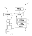
- FIG. 1 is a configuration diagram of an elevator to which a temperature estimation system according to a first embodiment is applied.
- FIG. 2 is a diagram illustrating an example of a thermal model of the temperature estimation system according to the first embodiment.
- FIG. 2 is a diagram illustrating an example of a thermal model of the temperature estimation system according to the first embodiment.
- 5 is a flowchart showing an example of the operation of the temperature estimation system according to the first embodiment.
- 1 is a hardware configuration diagram of a main part of a temperature estimation system according to a first embodiment.
- FIG. 11 is a configuration diagram of an elevator to which a temperature estimation system according to a second embodiment is applied.
- FIG. 11 is a configuration diagram of an elevator to which a temperature estimation system according to a third embodiment is applied.
- FIG. 1 is a configuration diagram of an elevator to which a temperature estimation system according to a first embodiment is applied.
- Elevator 1 is applied to buildings with multiple floors.
- a hoistway 2 for elevator 1 is provided in the building.
- Hoistway 2 is a long space in the vertical direction that spans the multiple floors of the building.
- Elevator 1 includes a hoisting machine 3, a main rope 4, a car 5, a counterweight 6, and a control device 7.
- the hoist 3 has a sheave.
- the hoist 3 is a device that has the function of generating torque to rotate the sheave.
- the hoist 3 includes, for example, a motor that generates torque.
- the main rope 4 is wound around a sheave of the hoist 3.
- the main rope 4 suspends the car 5 in the hoistway 2, thereby supporting the load of the car 5.
- the main rope 4 suspends the counterweight 6 in the hoistway 2, thereby supporting the load of the counterweight 6.
- the main rope 4 may be, for example, a strand rope or a belt rope.
- the car 5 and counterweight 6 run in opposite directions in the hoistway 2 as the main rope 4 moves with the rotation of the sheave of the hoisting machine 3.
- the car 5 is a device that transports passengers and the like between multiple floors by running vertically inside the hoistway 2.
- the counterweight 6 is a device that balances the load on the main rope 4 between the car 5 on both sides of the sheave of the hoisting machine 3.
- the car 5 and counterweight 6 run vertically inside the hoistway 2 by being guided, for example, by a guide rail (not shown).
- the control device 7 is a device that controls the operation of the elevator 1.
- the control device 7 controls, for example, the running of the car 5 in response to a call. In this example, the running of the car 5 from when it leaves the departure floor to when it stops at the destination floor is considered to be one run of the car 5.
- the control device 7 also controls, for example, the opening and closing of the doors provided on the car 5 of the elevator 1.
- the control device 7 holds control information related to the control of the elevator 1.
- the control information includes parameters that are causally related to one or both of the transient heat generation and cooling of each device that constitutes the elevator 1.
- the parameters may be continuous, may be discrete, or may represent one of multiple options.
- the control information includes discontinuous values that represent the operation mode of the elevator 1, such as an inverter drive command signal, a fan drive command signal, a door open command signal, and a door close command signal.
- the control information includes continuous values, such as a motor current command value and a car speed command value.
- the inverter is, for example, a device that outputs a drive current to the hoist 3.
- the fan is, for example, a device that blows air into the air-cooled equipment that makes up the elevator 1.
- the temperature estimation system 8 is applied to the elevator 1.
- the temperature estimation system 8 is a system that estimates the temperature of a preset temperature estimation point in the elevator 1 based on a preset thermal model.
- the temperature estimation point is a point that corresponds to equipment constituting the elevator 1 and is the subject of temperature estimation.
- the temperature estimation point may be a point corresponding to equipment such as the control device 7 or the hoist 3, or may be a point corresponding to other equipment.
- the temperature estimation system 8 may be a system that estimates the temperature of multiple temperature estimation points.
- a thermal model may be set individually for each temperature estimation point. Multiple temperature estimation points may be set for each equipment constituting the elevator 1.
- the temperature estimation points may be set for some or all of the magnet temperature and winding temperature of a permanent magnet motor, the bearing temperature, the chip temperature and case temperature of a power semiconductor, the electrolytic capacitor temperature, or the battery temperature.
- the temperature estimation system 8 includes a control device 7 of the elevator 1.
- the temperature estimation system 8 includes an ambient temperature sensor 9, a memory unit 10, and a calculation unit 11.
- some or all of the functions of the memory unit 10 and the calculation unit 11 may be installed in a device external to the elevator 1, or may be installed in equipment such as the control device 7 of the elevator 1.
- the ambient temperature sensor 9 is a sensor that measures the ambient temperature of the elevator 1.
- the ambient temperature of the elevator 1 is, for example, the temperature around the equipment that constitutes the elevator 1, which represents the temperature of the operating environment in which the equipment operates.
- the ambient temperature sensor 9 is preferably installed in a position where the impact of local heat generation by the equipment that constitutes the elevator 1 is small.
- the ambient temperature sensor 9 is installed, for example, below the control device 7.
- the ambient temperature sensor 9 measures the ambient temperature at the installed position.
- the temperature estimation system 8 may be equipped with multiple ambient temperature sensors 9 installed in different positions.
- the memory unit 10 is a part equipped with a function for storing information.
- the memory unit 10 includes a parameter memory area 12 and a threshold memory area 13.
- the parameter memory area 12 is a memory area that stores the parameters of the thermal model.
- the threshold memory area 13 is a memory area that stores the temperature protection thresholds of the equipment of the elevator 1.
- the temperature protection thresholds are temperature thresholds that are set in advance for each temperature estimation point in order to provide temperature protection for the equipment that corresponds to the temperature estimation point.
- the calculation unit 11 is a part equipped with a function for performing temperature estimation calculations at the temperature estimation point.
- the calculation unit 11 receives control information for the elevator 1 from the control device 7.
- the calculation unit 11 receives ambient temperature measured by the ambient temperature sensor 9 from the ambient temperature sensor 9.
- the calculation unit 11 reads the parameters of the thermal model stored in the parameter storage area 12 of the storage unit 10. For example, as a temperature estimation calculation, the calculation unit 11 receives the control information for the elevator 1 and the parameters of the thermal model as input and calculates a temperature rise value at the temperature estimation point.
- the calculation unit 11 adds the calculated temperature rise value to the ambient temperature and outputs a time series of temperature fluctuations at the temperature estimation point as the calculation result.
- the calculation unit 11 may perform temperature estimation calculations sequentially in real time, or may perform them intermittently, such as for each trip of the elevator 1 or after a certain period of time has elapsed.
- the frequency of temperature estimation calculations by the calculation unit 11 may be set for each temperature estimation point depending on the thermal time constant of the equipment to which the temperature estimation point corresponds.
- the frequency of temperature estimation calculations by the calculation unit 11 is, for example, every few seconds to every few hours.
- the calculation unit 11 compares the estimated temperature calculated for the temperature estimation point with the temperature protection threshold corresponding to the temperature estimation point. When the estimated temperature of the temperature estimation point exceeds the temperature protection threshold corresponding to the temperature estimation point, the calculation unit 11 outputs an alert signal to the control device 7 that applies operational protection to the equipment corresponding to the temperature estimation point.
- the alert signal may be a signal instructing an emergency stop of the car 5's travel, a signal instructing the car 5 to stop at the nearest floor, or a simple warning, depending on the severity of the incident caused by an abnormality in the equipment.
- the control device 7 controls the operation of the elevator 1 in accordance with the instruction.
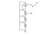
- FIG. 2A and 2B are diagrams illustrating an example of a thermal model of the temperature estimation system according to the first embodiment.
- the thermal model is a thermal circuit model including an RC ladder 14 and a heat flow source 15.
- FIG. 2A a thermal circuit model of a one-dimensional three-stage Foster network connection is shown.
- FIG. 2B a thermal circuit model of a one-dimensional three-stage Cauer network connection is shown.
- the RC ladder 14 is composed of thermal resistance 16 and thermal capacitance 17 connected in a ladder shape.
- the RC ladder 14 is composed of a Foster network or a Cauer network.
- the thermal resistance 16 and the thermal capacitance 17 are connected in one or more dimensions and in one or more stages.
- the resistance value of the thermal resistance 16 is expressed, for example, as a quantity in units of K/W.
- the capacitance value of the thermal capacitance 17 is expressed, for example, as a quantity in units of Ws/K.
- the heat flow rate of the heat flow source 15 is expressed, for example, as a quantity in units of W.
- the thermal circuit model is set independently for each temperature estimation point.
- the individual thermal models become simpler, thereby shortening the calculation time. This also tends to improve the temperature estimation accuracy. Note that in individual thermal models, a sufficiently high estimation accuracy can often be obtained with a one-dimensional RC ladder 14, but the RC ladder 14 may be expanded to two or more dimensions as necessary.
- the heat flow source 15 uses the control information of the elevator 1 as an argument and expresses the change over time in the heat generation or cooling state of the equipment that affects each temperature estimation point as a change in the magnitude of the heat flow.
- the heat flow source 15 expresses the change over time in the heat generation or cooling state of other equipment, such as equipment surrounding the equipment corresponding to the temperature estimation point, as a change in the magnitude of the heat flow.
- the heat flow source 15 is configured, for example, by an arbitrary function such as that expressed by the following equation (1).
- tn represents the time at the n-th point in the time series.
- P( tn ) represents the heat flow rate of the heat flow source 15 at time tn .
- xi ( tn ) represents the value of the i-th control information of the elevator 1 at time tn .
- Aj represents the j-th parameter among the constant parameters of the thermal model that are independent of time.
- Tn represents the temperature of the temperature estimation point at the n-th point in the time series.
- the function fk is the k-th function among the preset functions that constitute the model of the heat flow source 15.
- the model of the heat flow source 15 is represented by the sum of the functions fk .
- n, i, j, and k are natural numbers.
- the model of the heat flow source 15 may be the sum of three or less or five or more functions, or may be a combination by the product or composition of multiple functions.
- Each function f k is preferably a function that does not accumulate errors over time. Each function f k is preferably a function whose absolute value does not diverge to infinity over time. Each function f k may be a function determined by a constant parameter, such as function f 1 in formula (1). Each function f k may include control information x 1 as an argument, such as function f 2 in formula (1). Each function f k may include multiple constant parameters, such as function f 3 in formula (1). Each function f k may include one or both of a first-order lag element and a dead time element, such as function f 3 in formula (1).
- each function f k may also use a temperature at a past time as an argument, such as function f 4 in formula (1).
- the thermal model can more accurately represent the thermal behavior of the equipment of the elevator 1. Note that, since the control information of the elevator 1 required when creating a model of the heat flow source 15 differs depending on each temperature estimation point, the model formula of the heat flow source 15 differs for each temperature estimation point.
- the thermal model includes the resistance value of the thermal resistance 16 and the capacitance value of the heat capacitance 17 of the RC ladder 14, and the parameter A j of the heat flow source 15 as parameters of the thermal model.
- These parameters of the thermal model are identified in a test carried out in advance. In the test, the elevator 1 is operated under a plurality of operating conditions. The parameters of the thermal model are identified for each temperature estimation point by a regression analysis method based on the control information corresponding to these operating conditions, the temperature of the temperature estimation point measured in the operation, and the ambient temperature of the elevator 1.
- the resistance value of the thermal resistance 16 and the capacitance value of the heat capacitance 17 of the RC ladder 14 as parameters of the model do not need to be directly related to the physical thermal resistance 16 and heat capacitance 17 of any device of the elevator 1, etc.
- the model of the heat flow source 15 does not need to be directly related to the physical amount of heat generated in any device of the elevator 1, etc.
- the following formulas (2) to (4) show examples of the calculations that are sequentially performed in the calculation unit 11 using a thermal model that includes a one-dimensional Foster network RC ladder 14.
- tn represents the time at the nth point in the time series.
- P( tn ) represents the heat flow rate of the heat flow source 15 at time tn .
- Rm represents the resistance value of the thermal resistor 16 at the mth stage of the RC ladder 14.
- Cm represents the capacitance value of the heat capacitance 17 at the mth stage of the RC ladder 14.
- P Cm ( tn ) represents the heat flow rate flowing through the heat capacitance 17 at the mth stage of the RC ladder 14 at time tn .
- T( tn ) represents the temperature rise value of the temperature estimation point at time tn .
- the temperature rise value T( tn ) of the temperature estimation point is expressed as shown in formula (4) by the sum of the temperature differences Tm ( tn ) at each stage of the RC ladder 14 over all stages.
- the temperature difference Tm at each stage of the RC ladder 14 is calculated using formula (2).
- the heat flow rate P Cm (t n-1 ) flowing through the heat capacity 17 at the previous time point t n-1 is required.
- This heat flow rate P Cm (t n-1 ) is calculated in advance using equation (3) when calculating the time point t n-1 prior to the calculation of time point t n .
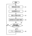
- FIG. 3 is a flowchart showing an example of the operation of the temperature estimation system according to the first embodiment.
- step S1 the ambient temperature sensor 9 measures the ambient temperature of the elevator 1. After that, the processing of the temperature estimation system 8 proceeds to step S2.
- step S2 the control device 7 outputs control information for the elevator 1 to the calculation unit 11. After that, the processing of the temperature estimation system 8 proceeds to step S3.
- step S3 the calculation unit 11 calculates the temperature rise value of the temperature estimation point using a thermal model based on the control information. After that, the processing of the temperature estimation system 8 proceeds to step S4.
- step S4 the calculation unit 11 adds the temperature rise value to the ambient temperature to estimate the temperature at the temperature estimation point.
- the calculation unit 11 outputs the estimated temperature as time-series data to, for example, the control device 7. After that, the processing of the temperature estimation system 8 proceeds to step S5.
- step S5 the calculation unit 11 determines whether the estimated temperature of the temperature estimation point exceeds the temperature protection threshold corresponding to that temperature estimation point. If it is determined that the estimated temperature exceeds the temperature protection threshold, the processing of the temperature estimation system 8 proceeds to step S6. On the other hand, if it is not determined that the estimated temperature exceeds the temperature protection threshold, the processing of the temperature estimation system 8 proceeds to step S1.
- step S6 the calculation unit 11 outputs an alert signal to the control device 7.
- the control device 7 controls the elevator 1 based on the alert signal. After that, the processing of the temperature estimation system 8 proceeds to step S1.
- the temperature estimation system 8 includes the control device 7 of the elevator 1, the ambient temperature sensor 9, and the calculation unit 11.
- the ambient temperature sensor 9 measures the ambient temperature of the elevator 1.
- the calculation unit 11 performs a temperature estimation calculation of a preset temperature estimation point in the elevator 1 based on a preset thermal model.
- the calculation unit 11 receives the ambient temperature input from the ambient temperature sensor 9, the parameters of the thermal model, and control information that is causally related to transient heat generation or cooling and is input from the control device 7.
- the calculation unit 11 outputs a time series of temperature fluctuations at the temperature estimation point as a calculation result.
- the thermal model is a thermal circuit model including the RC ladder 14 and the heat flow source 15.
- the parameters of the thermal model are identified in advance by a regression analysis method based on the control information according to the operating conditions of the elevator 1 and the temperature of the temperature estimation point and the ambient temperature measured in a test performed in advance under the operating conditions.
- the RC ladder 14 includes thermal resistances 16 and thermal capacitances 17 that are connected in one or more dimensions and at one or more stages by a Foster network or a Cauer network.
- the heat flow source 15 uses control information as an argument to express the temporal change in the heating or cooling state of the equipment that affects the temperature of the temperature estimation point by the change in the magnitude of the heat flow.
- the temperature estimation system 8 estimates the temperature at the temperature estimation point using a thermal model including the RC ladder 14 and the heat flow source 15.
- the time-dependent changes in the heat generation or cooling of the surrounding equipment are expressed by the change in the magnitude of the heat flow of the heat flow source 15.
- This makes it possible to improve the accuracy of the temperature estimation at the temperature estimation point without using an advanced model such as the finite element method.
- the structural function of the equipment changes over time, for example, when the on and off states of the cooling fan that cools the equipment corresponding to the temperature estimation point are switched over time, the accuracy of the temperature estimation at the temperature estimation point can be improved by the change in the heat flow via the control information.
- the thermal model is composed of the RC ladder 14, the required calculation time and computing power are not excessive. Therefore, the temperature at the temperature estimation point can be estimated in a short time by simple calculation, and real-time constant temperature estimation is possible at low cost.
- the results of the temperature estimation can be used for various applications in the maintenance management of the elevator 1, such as estimating the lifespan from the operating temperature of each equipment to plan maintenance replacement, or using the operating temperature of each equipment for quality control.
- the thermal model also includes at least one of a first-order lag and a dead time element in the heat flow source 15.
- This configuration makes it possible to improve the accuracy of temperature estimation predictions at the temperature estimation point even in cases where the influence of heat generation or cooling from surrounding devices is greater than the self-heating of the device corresponding to the temperature estimation point, and temperature changes lag behind changes in control information.
- the heat flow source 15 of the thermal model includes an element that takes the temperature of the temperature estimation point as an argument.
- This configuration can improve the prediction accuracy of temperature estimation at the temperature estimation point even when the time constant of the heating process and the time constant of the cooling process are different.
- the calculation unit 11 when the estimated temperature at the temperature estimation point exceeds a temperature protection threshold preset for the equipment of elevator 1, the calculation unit 11 outputs an alert signal to the control device 7 to activate operation protection for the equipment.
- This configuration makes it possible to use the results of temperature estimation at the temperature estimation point to provide advanced sensorless temperature protection for the device corresponding to the temperature estimation point, without the need for a sensor that directly measures the temperature at that point.
- FIG. 4 is a hardware configuration diagram of a main part of the temperature estimation system according to the first embodiment.
- Each function of the temperature estimation system 8 may be realized by a processing circuit.
- the processing circuit includes at least one processor 100a and at least one memory 100b.
- the processing circuit may include at least one dedicated hardware 200 in addition to or in place of the processor 100a and memory 100b.
- each function of the temperature estimation system 8 is realized by software, firmware, or a combination of software and firmware. At least one of the software and firmware is written as a program. The program is stored in the memory 100b. The processor 100a realizes each function of the temperature estimation system 8 by reading and executing the program stored in the memory 100b.
- the processor 100a is also called a CPU (Central Processing Unit), processing device, arithmetic unit, microprocessor, microcomputer, or DSP.
- the memory 100b is composed of non-volatile or volatile semiconductor memory such as RAM, ROM, flash memory, EPROM, and EEPROM.
- processing circuitry comprises dedicated hardware 200
- the processing circuitry may be implemented, for example, as a single circuit, a composite circuit, a programmed processor, a parallel programmed processor, an ASIC, an FPGA, or a combination thereof.
- Each function of the temperature estimation system 8 can be realized by a processing circuit. Alternatively, each function of the temperature estimation system 8 can be realized collectively by a processing circuit. Some of the functions of the temperature estimation system 8 may be realized by dedicated hardware 200, and other parts may be realized by software or firmware. In this way, the processing circuit realizes each function of the temperature estimation system 8 by dedicated hardware 200, software, firmware, or a combination of these.
- Embodiment 2 In the second embodiment, differences from the example disclosed in the first embodiment will be described in particular detail. For features not described in the second embodiment, any of the features of the example disclosed in the first embodiment may be adopted.
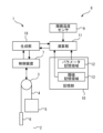
- FIG. 5 is a configuration diagram of an elevator to which the temperature estimation system according to the second embodiment is applied.
- the temperature estimation system 8 includes a generation unit 18.
- some or all of the functions of the memory unit 10, the calculation unit 11, and the generation unit 18 may be mounted on an external device of the elevator 1, or may be mounted on equipment such as the control device 7 of the elevator 1.
- the generation unit 18 is a part equipped with a function for generating control information for each run of the car 5 of the elevator 1 before that run.
- the generation unit 18 receives input of running information including the current floor and destination floor of the car 5 from the control device 7 immediately before the car 5 starts running. Based on the running information, the generation unit 18 generates control information for one run when that run is performed at each of a number of preset rated speeds before that run.
- the generation unit 18 outputs the control information generated for each rated speed to the calculation unit 11.
- the calculation unit 11 estimates the temperature at the temperature estimation point when the car 5 runs at each rated speed based on the control information generated by the generation unit 18 for each rated speed.
- the calculation unit 11 outputs to the control device 7 the fastest rated speed among the multiple rated speeds at which the estimated temperature does not exceed the temperature protection threshold corresponding to the temperature estimation point.
- the control device 7 controls the car 5 to travel from the current floor to the destination floor based on the rated speed input from the calculation unit 11.
- the car 5 travels based on the rated speed selected after comparing the estimated temperatures for multiple rated speeds with the temperature protection threshold. As a result, even if the temperature of the equipment becomes high, the elevator 1 can continue to provide service by reducing the travel speed to a level that does not trigger temperature protection for the equipment that constitutes the elevator 1.
- Embodiment 3 In the third embodiment, differences from the examples disclosed in the first or second embodiment will be described in particular detail. For features not described in the third embodiment, any of the features of the examples disclosed in the first or second embodiment may be adopted.
- FIG. 6 is a configuration diagram of an elevator to which the temperature estimation system according to the third embodiment is applied.
- the temperature estimation system 8 includes a gateway 19 and a data server 20.
- the gateway 19 is a device that can be connected to a public line network such as the Internet or a telephone line network.
- the gateway 19 is provided, for example, in a building to which the elevator 1 is applied.
- the gateway 19 is connected, for example, to the calculation unit 11.
- the data server 20 is a server equipped with a function for accumulating and storing data about the elevator 1.
- the data server 20 is an example of a storage unit.
- the data server 20 may be composed of, for example, one or more server devices.
- the data server 20 may be constructed on a cloud service.
- the data server 20 is provided, for example, outside the building to which the elevator 1 is applied.
- the data server 20 is connected to the gateway 19, for example, via a public line network.
- the calculation unit 11 uploads the estimated temperature for each temperature estimation point to the data server 20 via the gateway 19.
- the data server 20 accumulates and stores the time series history of the estimated temperature for each temperature estimation point uploaded from the calculation unit 11 for long-term storage.
- the temperature estimation does not necessarily have to be performed in real time.
- some or all of the functions of the calculation unit 11 and the memory unit 10 may be mounted on the data server 20.
- the calculation unit 11 obtains information such as control information for the elevator 1 and the measured value of the ambient temperature from the control device 7, for example, via the gateway 19.
- the temperature estimation system disclosed herein can be applied to elevators.
Landscapes
- Engineering & Computer Science (AREA)
- Automation & Control Theory (AREA)
- Elevator Control (AREA)
Abstract
Description
図1は、実施の形態1に係る温度推定システムが適用されるエレベーターの構成図である。
図2Aおよび図2Bは、実施の形態1に係る温度推定システムの熱モデルの例を示す図である。

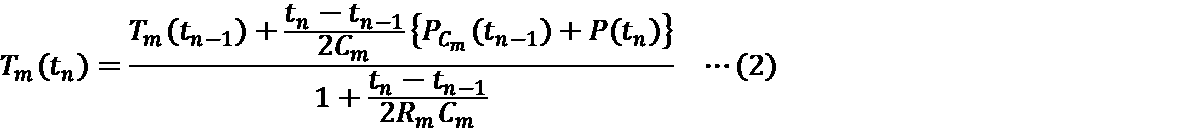
図3は、実施の形態1に係る温度推定システムの動作の例を示すフローチャートである。
図4は、実施の形態1に係る温度推定システムの主要部のハードウェア構成図である。
実施の形態2において、実施の形態1で開示される例と相違する点について特に詳しく説明する。実施の形態2で説明しない特徴については、実施の形態1で開示される例のいずれの特徴が採用されてもよい。
実施の形態3において、実施の形態1または実施の形態2で開示される例と相違する点について特に詳しく説明する。実施の形態3で説明しない特徴については、実施の形態1または実施の形態2で開示される例のいずれの特徴が採用されてもよい。
Claims (6)
- エレベーターの制御装置と、
エレベーターの周囲温度を測定する周囲温度センサと、
エレベーターにおいて予め設定された温度推定点の温度推定演算を、予め設定された熱モデルに基づいて行う演算部と、
を備え、
前記演算部による前記温度推定演算は、前記周囲温度センサから入力される前記周囲温度、前記熱モデルのパラメータ、および過渡的な発熱または冷却と因果関係があり前記制御装置から入力される制御情報を入力とし、前記温度推定点の温度変動の時系列を計算結果として出力する演算であり、
前記熱モデルは、RCラダーおよび熱流源を含む熱回路モデルであり、
前記熱モデルの前記パラメータは、エレベーターの運転条件に応じた前記制御情報と、予め実施される当該運転条件下の試験において測定される前記温度推定点の温度および前記周囲温度とに基づいて、回帰解析的手法により予め同定され、
前記RCラダーは、フォスターネットワークまたはカウアーネットワークにより1次元以上かつ1段以上で接続された熱抵抗および熱容量を含み、
前記熱流源は、前記制御情報を引数として、前記温度推定点の温度に影響する機器の発熱状態または冷却状態の時間的変化を、熱流量の大きさの変化によって表現する、
エレベーターの温度推定システム。 - 前記熱モデルは、一次遅れおよびむだ時間の少なくとも一方の要素を前記熱流源に含む、
請求項1に記載のエレベーターの温度推定システム。 - 前記熱モデルの前記熱流源は、温度を引数とする要素を含む、
請求項1または請求項2に記載のエレベーターの温度推定システム。 - 前記演算部は、エレベーターの機器について予め設定された温度保護閾値を前記温度推定点の温度の推定値が超えるときに、当該機器の動作保護を掛けるアラート信号を前記制御装置に出力する、
請求項1から請求項3のいずれか一項に記載のエレベーターの温度推定システム。 - エレベーターの各回の走行について、前記制御装置から入力されるエレベーターのかごの現在階床および目的階床を含む情報に基づいて、予め設定された複数の定格速度で当該走行をそれぞれ実行した場合の前記制御情報を当該走行の前に生成する生成部
を備え、
前記演算部は、前記生成部から入力される前記複数の定格速度で当該走行をそれぞれ実行した場合の前記制御情報に基づいて、前記複数の定格速度で当該走行をそれぞれ実行した場合の前記温度推定点の温度を推定し、前記複数の定格速度のうち推定する温度が前記温度保護閾値を超えない中で最も速い定格速度を前記制御装置に出力し、
前記制御装置は、前記演算部から入力される定格速度に基づいて当該走行を実行する、
請求項4に記載のエレベーターの温度推定システム。 - 前記演算部が推定する前記温度推定点の温度を蓄積して記憶する蓄積部
を備える、請求項1から請求項5のいずれか一項に記載のエレベーターの温度推定システム。
Priority Applications (3)
| Application Number | Priority Date | Filing Date | Title |
|---|---|---|---|
| PCT/JP2023/004416 WO2024166317A1 (ja) | 2023-02-09 | 2023-02-09 | エレベーターの温度推定システム |
| JP2024576011A JPWO2024166317A1 (ja) | 2023-02-09 | 2023-02-09 | |
| CN202380066352.4A CN120584082A (zh) | 2023-02-09 | 2023-02-09 | 电梯的温度估计系统 |
Applications Claiming Priority (1)
| Application Number | Priority Date | Filing Date | Title |
|---|---|---|---|
| PCT/JP2023/004416 WO2024166317A1 (ja) | 2023-02-09 | 2023-02-09 | エレベーターの温度推定システム |
Publications (1)
| Publication Number | Publication Date |
|---|---|
| WO2024166317A1 true WO2024166317A1 (ja) | 2024-08-15 |
Family
ID=92262141
Family Applications (1)
| Application Number | Title | Priority Date | Filing Date |
|---|---|---|---|
| PCT/JP2023/004416 Ceased WO2024166317A1 (ja) | 2023-02-09 | 2023-02-09 | エレベーターの温度推定システム |
Country Status (3)
| Country | Link |
|---|---|
| JP (1) | JPWO2024166317A1 (ja) |
| CN (1) | CN120584082A (ja) |
| WO (1) | WO2024166317A1 (ja) |
Citations (5)
| Publication number | Priority date | Publication date | Assignee | Title |
|---|---|---|---|---|
| WO2005030627A1 (ja) * | 2003-09-29 | 2005-04-07 | Mitsubishi Denki Kabushiki Kaisha | エレベータの制御装置 |
| JP2011063432A (ja) * | 2009-09-18 | 2011-03-31 | Toshiba Elevator Co Ltd | エレベータ制御装置 |
| JP2018511868A (ja) * | 2015-03-09 | 2018-04-26 | アドバンスト・マイクロ・ディバイシズ・インコーポレイテッドAdvanced Micro Devices Incorporated | デバイス状態に基づく電力制限の変更 |
| JP2021196302A (ja) * | 2020-06-17 | 2021-12-27 | 株式会社明電舎 | 推定装置 |
| US20220169479A1 (en) * | 2019-09-11 | 2022-06-02 | Kone Corporation | Method for reducing thermal stress of a power semiconductor switch, an electrical converter unit and an elevator |
-
2023
- 2023-02-09 CN CN202380066352.4A patent/CN120584082A/zh active Pending
- 2023-02-09 WO PCT/JP2023/004416 patent/WO2024166317A1/ja not_active Ceased
- 2023-02-09 JP JP2024576011A patent/JPWO2024166317A1/ja active Pending
Patent Citations (5)
| Publication number | Priority date | Publication date | Assignee | Title |
|---|---|---|---|---|
| WO2005030627A1 (ja) * | 2003-09-29 | 2005-04-07 | Mitsubishi Denki Kabushiki Kaisha | エレベータの制御装置 |
| JP2011063432A (ja) * | 2009-09-18 | 2011-03-31 | Toshiba Elevator Co Ltd | エレベータ制御装置 |
| JP2018511868A (ja) * | 2015-03-09 | 2018-04-26 | アドバンスト・マイクロ・ディバイシズ・インコーポレイテッドAdvanced Micro Devices Incorporated | デバイス状態に基づく電力制限の変更 |
| US20220169479A1 (en) * | 2019-09-11 | 2022-06-02 | Kone Corporation | Method for reducing thermal stress of a power semiconductor switch, an electrical converter unit and an elevator |
| JP2021196302A (ja) * | 2020-06-17 | 2021-12-27 | 株式会社明電舎 | 推定装置 |
Also Published As
| Publication number | Publication date |
|---|---|
| CN120584082A (zh) | 2025-09-02 |
| JPWO2024166317A1 (ja) | 2024-08-15 |
Similar Documents
| Publication | Publication Date | Title |
|---|---|---|
| CN101269767B (zh) | 电梯的维护管理系统 | |
| ES2394323T3 (es) | Disposición de elevador | |
| US9573789B2 (en) | Elevator load detection system and method | |
| EA009189B1 (ru) | Устройство для контроля двери лифта | |
| CN104163369A (zh) | 用于监视自动门的状况的配置和方法 | |
| US7837012B2 (en) | Control device for elevator | |
| EP3617117B1 (en) | Model development framework for remote monitoring condition-based maintenance | |
| CN113148807A (zh) | 用于操作电梯的方法 | |
| JP7517597B2 (ja) | エレベーターのモータの異常検出システム | |
| CN108367885B (zh) | 电梯的控制装置 | |
| JP7226671B2 (ja) | エレベーターの故障診断装置 | |
| JP5289574B2 (ja) | エレベータ制御装置 | |
| WO2024166317A1 (ja) | エレベーターの温度推定システム | |
| US11853046B2 (en) | Prediction of faulty behaviour of a converter based on temperature estimation with machine learning algorithm | |
| JP5005401B2 (ja) | エレベーター制御装置 | |
| US11740607B2 (en) | Method and system for monitoring condition of electric drives | |
| JP7593865B2 (ja) | 巻上機、巻上機システム、および状態推定装置 | |
| JP4486104B2 (ja) | エレベータの診断運転装置及び診断運転方法 | |
| CN113104688A (zh) | 电梯控制装置和电梯控制方法 | |
| CN114901580A (zh) | 电梯的判定装置 | |
| JP6839259B1 (ja) | 昇降機の群管理制御装置 | |
| JPH09145109A (ja) | 道路トンネルの換気自動制御装置 | |
| CN119503562A (zh) | 信息系统以及信息取得方法 | |
| WO2024209548A1 (ja) | エレベーターの管理システム | |
| CN119998223A (zh) | 卷扬机、卷扬机系统和状态推算系统 |
Legal Events
| Date | Code | Title | Description |
|---|---|---|---|
| 121 | Ep: the epo has been informed by wipo that ep was designated in this application |
Ref document number: 23921148 Country of ref document: EP Kind code of ref document: A1 |
|
| WWE | Wipo information: entry into national phase |
Ref document number: 2024576011 Country of ref document: JP |
|
| WWE | Wipo information: entry into national phase |
Ref document number: 202380066352.4 Country of ref document: CN |
|
| WWP | Wipo information: published in national office |
Ref document number: 202380066352.4 Country of ref document: CN |
|
| NENP | Non-entry into the national phase |
Ref country code: DE |
|
| 122 | Ep: pct application non-entry in european phase |
Ref document number: 23921148 Country of ref document: EP Kind code of ref document: A1 |