WO2024172014A1 - 転がり軸受 - Google Patents
転がり軸受 Download PDFInfo
- Publication number
- WO2024172014A1 WO2024172014A1 PCT/JP2024/004770 JP2024004770W WO2024172014A1 WO 2024172014 A1 WO2024172014 A1 WO 2024172014A1 JP 2024004770 W JP2024004770 W JP 2024004770W WO 2024172014 A1 WO2024172014 A1 WO 2024172014A1
- Authority
- WO
- WIPO (PCT)
- Prior art keywords
- balls
- rolling bearing
- diameter side
- grease
- Prior art date
- Legal status (The legal status is an assumption and is not a legal conclusion. Google has not performed a legal analysis and makes no representation as to the accuracy of the status listed.)
- Ceased
Links
Images






Classifications
-
- F—MECHANICAL ENGINEERING; LIGHTING; HEATING; WEAPONS; BLASTING
- F16—ENGINEERING ELEMENTS AND UNITS; GENERAL MEASURES FOR PRODUCING AND MAINTAINING EFFECTIVE FUNCTIONING OF MACHINES OR INSTALLATIONS; THERMAL INSULATION IN GENERAL
- F16C—SHAFTS; FLEXIBLE SHAFTS; ELEMENTS OR CRANKSHAFT MECHANISMS; ROTARY BODIES OTHER THAN GEARING ELEMENTS; BEARINGS
- F16C33/00—Parts of bearings; Special methods for making bearings or parts thereof
- F16C33/30—Parts of ball or roller bearings
- F16C33/38—Ball cages
- F16C33/3887—Details of individual pockets, e.g. shape or ball retaining means
-
- F—MECHANICAL ENGINEERING; LIGHTING; HEATING; WEAPONS; BLASTING
- F16—ENGINEERING ELEMENTS AND UNITS; GENERAL MEASURES FOR PRODUCING AND MAINTAINING EFFECTIVE FUNCTIONING OF MACHINES OR INSTALLATIONS; THERMAL INSULATION IN GENERAL
- F16C—SHAFTS; FLEXIBLE SHAFTS; ELEMENTS OR CRANKSHAFT MECHANISMS; ROTARY BODIES OTHER THAN GEARING ELEMENTS; BEARINGS
- F16C33/00—Parts of bearings; Special methods for making bearings or parts thereof
- F16C33/30—Parts of ball or roller bearings
- F16C33/38—Ball cages
- F16C33/3837—Massive or moulded cages having cage pockets surrounding the balls, e.g. machined window cages
- F16C33/3862—Massive or moulded cages having cage pockets surrounding the balls, e.g. machined window cages comprising two annular parts joined together
- F16C33/3875—Massive or moulded cages having cage pockets surrounding the balls, e.g. machined window cages comprising two annular parts joined together made from plastic, e.g. two injection moulded parts joined by a snap fit
-
- F—MECHANICAL ENGINEERING; LIGHTING; HEATING; WEAPONS; BLASTING
- F16—ENGINEERING ELEMENTS AND UNITS; GENERAL MEASURES FOR PRODUCING AND MAINTAINING EFFECTIVE FUNCTIONING OF MACHINES OR INSTALLATIONS; THERMAL INSULATION IN GENERAL
- F16C—SHAFTS; FLEXIBLE SHAFTS; ELEMENTS OR CRANKSHAFT MECHANISMS; ROTARY BODIES OTHER THAN GEARING ELEMENTS; BEARINGS
- F16C33/00—Parts of bearings; Special methods for making bearings or parts thereof
- F16C33/30—Parts of ball or roller bearings
- F16C33/38—Ball cages
- F16C33/41—Ball cages comb-shaped
- F16C33/418—Details of individual pockets, e.g. shape or ball retaining means
-
- F—MECHANICAL ENGINEERING; LIGHTING; HEATING; WEAPONS; BLASTING
- F16—ENGINEERING ELEMENTS AND UNITS; GENERAL MEASURES FOR PRODUCING AND MAINTAINING EFFECTIVE FUNCTIONING OF MACHINES OR INSTALLATIONS; THERMAL INSULATION IN GENERAL
- F16C—SHAFTS; FLEXIBLE SHAFTS; ELEMENTS OR CRANKSHAFT MECHANISMS; ROTARY BODIES OTHER THAN GEARING ELEMENTS; BEARINGS
- F16C33/00—Parts of bearings; Special methods for making bearings or parts thereof
- F16C33/30—Parts of ball or roller bearings
- F16C33/38—Ball cages
- F16C33/42—Ball cages made from wire or sheet metal strips
- F16C33/422—Ball cages made from wire or sheet metal strips made from sheet metal
- F16C33/427—Ball cages made from wire or sheet metal strips made from sheet metal from two parts, e.g. ribbon cages with two corrugated annular parts
-
- F—MECHANICAL ENGINEERING; LIGHTING; HEATING; WEAPONS; BLASTING
- F16—ENGINEERING ELEMENTS AND UNITS; GENERAL MEASURES FOR PRODUCING AND MAINTAINING EFFECTIVE FUNCTIONING OF MACHINES OR INSTALLATIONS; THERMAL INSULATION IN GENERAL
- F16C—SHAFTS; FLEXIBLE SHAFTS; ELEMENTS OR CRANKSHAFT MECHANISMS; ROTARY BODIES OTHER THAN GEARING ELEMENTS; BEARINGS
- F16C33/00—Parts of bearings; Special methods for making bearings or parts thereof
- F16C33/30—Parts of ball or roller bearings
- F16C33/66—Special parts or details in view of lubrication
- F16C33/6603—Special parts or details in view of lubrication with grease as lubricant
- F16C33/6607—Retaining the grease in or near the bearing
- F16C33/6614—Retaining the grease in or near the bearing in recesses or cavities provided in retainers, races or rolling elements
-
- F—MECHANICAL ENGINEERING; LIGHTING; HEATING; WEAPONS; BLASTING
- F16—ENGINEERING ELEMENTS AND UNITS; GENERAL MEASURES FOR PRODUCING AND MAINTAINING EFFECTIVE FUNCTIONING OF MACHINES OR INSTALLATIONS; THERMAL INSULATION IN GENERAL
- F16C—SHAFTS; FLEXIBLE SHAFTS; ELEMENTS OR CRANKSHAFT MECHANISMS; ROTARY BODIES OTHER THAN GEARING ELEMENTS; BEARINGS
- F16C19/00—Bearings with rolling contact, for exclusively rotary movement
- F16C19/02—Bearings with rolling contact, for exclusively rotary movement with bearing balls essentially of the same size in one or more circular rows
- F16C19/04—Bearings with rolling contact, for exclusively rotary movement with bearing balls essentially of the same size in one or more circular rows for radial load mainly
- F16C19/06—Bearings with rolling contact, for exclusively rotary movement with bearing balls essentially of the same size in one or more circular rows for radial load mainly with a single row or balls
-
- F—MECHANICAL ENGINEERING; LIGHTING; HEATING; WEAPONS; BLASTING
- F16—ENGINEERING ELEMENTS AND UNITS; GENERAL MEASURES FOR PRODUCING AND MAINTAINING EFFECTIVE FUNCTIONING OF MACHINES OR INSTALLATIONS; THERMAL INSULATION IN GENERAL
- F16C—SHAFTS; FLEXIBLE SHAFTS; ELEMENTS OR CRANKSHAFT MECHANISMS; ROTARY BODIES OTHER THAN GEARING ELEMENTS; BEARINGS
- F16C2226/00—Joining parts; Fastening; Assembling or mounting parts
- F16C2226/50—Positive connections
- F16C2226/70—Positive connections with complementary interlocking parts
- F16C2226/74—Positive connections with complementary interlocking parts with snap-fit, e.g. by clips
-
- F—MECHANICAL ENGINEERING; LIGHTING; HEATING; WEAPONS; BLASTING
- F16—ENGINEERING ELEMENTS AND UNITS; GENERAL MEASURES FOR PRODUCING AND MAINTAINING EFFECTIVE FUNCTIONING OF MACHINES OR INSTALLATIONS; THERMAL INSULATION IN GENERAL
- F16C—SHAFTS; FLEXIBLE SHAFTS; ELEMENTS OR CRANKSHAFT MECHANISMS; ROTARY BODIES OTHER THAN GEARING ELEMENTS; BEARINGS
- F16C2300/00—Application independent of particular apparatuses
- F16C2300/20—Application independent of particular apparatuses related to type of movement
- F16C2300/22—High-speed rotation
Definitions
- This invention relates to a rolling bearing incorporating a retainer consisting of two annular bodies facing each other in the axial direction.
- an arc-shaped cutout is formed on the inner diameter side or outer diameter side of the pocket of the cage, and this cutout improves the scraping ability of grease adhering to the surface of the balls, thereby reducing the break-in time.
- some of the grease remaining in the stationary space is scraped off by the cutout, and heat generation is suppressed by supplying base oil between the balls and the pocket. While forming this cutout improves the scraping ability of grease, the centrifugal force acting on the cage rotating at high speed can deform the pocket so that the axial gap between the balls and the pocket narrows, causing interference between the balls and the pocket, which can deteriorate bearing parameters such as oil burn, abnormal wear, and heat generation.
- the shape of the cage pocket is cylindrical on the inner diameter side of the pitch circle of the balls to provide an escape, preventing interference between the balls and the pocket even if axial deformation occurs in the cage pocket due to centrifugal force.
- Patent Document 2 by making the inner diameter side of the pocket cylindrical, interference between the balls and the pocket on this inner diameter side can be prevented, but on the other hand, the gap between the balls and the pocket becomes larger, increasing the amount of grease that enters the pocket when operation begins, and the spatial volume inside the pocket increases, so the amount of grease that remains increases. As a result, there is a problem that the break-in time increases and the amount of heat generated by shear between the grease and the balls inside the pocket increases. Furthermore, by making the inner diameter side of the pocket cylindrical, the thickness of the pocket on this inner diameter side becomes smaller, reducing rigidity and increasing the amount of deformation due to centrifugal force, which may make it unsuitable for use in high-speed rotation.
- the objective of this invention is to provide a rolling bearing that prevents interference between the balls and the cage and has excellent high-speed rotation performance.
- the present invention provides: a ring-shaped body in which a plurality of pocket walls each having a recess that forms a pocket and a connecting plate portion that connects the pocket walls are alternately formed in a circumferential direction, and a cage in which a plurality of the pockets are formed in the circumferential direction by axially opposing two of the ring-shaped bodies; an inner ring having an inner ring raceway surface formed on an outer peripheral surface; an outer ring provided on an outer circumferential side of the inner ring and having an outer ring raceway surface formed on an inner circumferential surface; a plurality of balls interposed between the inner ring and the outer ring and held by the pockets formed in the cage;
- the rolling bearing has a spherical surface formed on the pocket wall portion so as to be out of contact with the balls when the balls are in contact with the circumferential ends of the pockets.
- a cutout portion can be formed on at least one of the inner diameter side and the outer diameter side of the pocket, making the radial width of the pocket wall portion smaller than the radial width of the connecting plate portion.
- the cutout portion has the effect of scraping off grease adhering to the balls, further reducing the break-in time.
- the spherical portion can be formed on the inner diameter side of the pocket, while the cylindrical portion can be formed on the outer diameter side of the pocket wall.
- the cylindrical portion functions as an escape portion.
- the circumferential wall surface of the spherical portion can be inclined along the radial direction of the pitch circle of the ball. In this way, the circumferential wall surface of the spherical portion does not provide resistance to the discharge of grease, suppressing the retention of grease in the pocket and further improving the dischargeability.
- the balls can be made of ceramics. This reduces the weight of the balls, reducing the impact when the balls collide with the cage, and improving quietness during high-speed rotation.
- a rolling bearing having a cage in which multiple pockets are formed in the circumferential direction by placing two annular bodies facing each other in the axial direction is configured so that a spherical portion that does not come into contact with the balls is formed on the pocket wall when the balls are in contact with the circumferential end of the pocket, thereby providing a rolling bearing with excellent high-speed rotation performance.
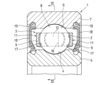
- FIG. 1 is a cross-sectional view showing one embodiment of a rolling bearing according to the present invention.
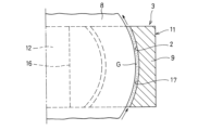
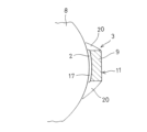
- 2 is a cross-sectional view of a main part of the rolling bearing shown in FIG. 1 ;
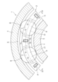
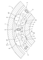
- 3 is a cross-sectional view taken along line III-III in FIG. 1.
- 4 is a cross-sectional view taken along line IV-IV in FIG.
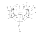
- FIG. 2 is a cross-sectional view showing a main portion of a first modified example of the rolling bearing shown in FIG. 6 is a cross-sectional view taken along line VI-VI in FIG.
- FIG. 6 is an axial cross-sectional view of a main part of the rolling bearing shown in FIG.
- FIG. 6 is a cross-sectional view showing a main part of the rolling bearing shown in FIG. 5 before deformation of the cage.
- FIG. 6 is a cross-sectional view showing a main part of the rolling bearing shown in FIG. 5 after deformation of the cage due to centrifugal force.
- FIG. 2 is a cross-sectional view showing a main part of a second modified example of the rolling bearing shown in FIG.
- FIG. 2 is a circumferential cross-sectional view of a main portion of a third modified example of the rolling bearing shown in FIG.
- FIG. 2 is an axial cross-sectional view of a main portion of a third modified example of the rolling bearing shown in FIG.
- the direction along the rotation axis of the rolling bearing 1 is called the axial direction
- the direction perpendicular to the rotation axis is called the radial direction
- the direction along the arc centered on the rotation axis is called the circumferential direction.
- the rolling bearing 1 is a ball bearing having a cage 3 in which multiple pockets 2 are formed at regular intervals in the circumferential direction, an inner ring 5 having an inner ring raceway surface 4 formed on its outer circumferential surface, an outer ring 7 provided on the outer circumferential side of the inner ring 5 and having an outer ring raceway surface 6 formed on its inner circumferential surface, and multiple balls 8 provided between the inner ring 5 and the outer ring 7 and held by the pockets 2 formed in the cage 3.
- the cage 3 is composed of two annular bodies 11 arranged axially opposite each other, in which a plurality of pocket walls 9 with recesses that form the pockets 2 and connecting plates 10 that connect the pocket walls 9 are alternately formed in the circumferential direction.
- the pocket walls 9 restrict the axial movement of the balls 8
- the connecting plates 10 restrict the circumferential movement of the balls 8.
- a spherical recess 12 is formed on the connecting plates 10 side of the pockets 2 so as to face the balls 8 circumferentially, and the balls 8 rotate while being guided by this spherical recess 12.
- This cage 3 is a ball guide type in which the cage 3 is positioned radially by contact between the inner surface of the pocket 2 and the balls 8. Therefore, the inner circumference of the cage 3 is not in contact with the inner ring 5, and the outer circumference of the cage 3 is not in contact with the outer ring 7.
- Each annular body 11 constituting the retainer 3 is formed by injection molding of synthetic resin.
- the two annular bodies 11 have the same shape and can be molded using the same mold.
- synthetic resins constituting each annular body 11 include thermoplastic resins such as polyamide (PA), polyphenylene sulfide (PPS), and polyether ether ketone (PEEK).
- PA polyamide
- PPS polyphenylene sulfide
- PEEK polyether ether ketone
- the synthetic resin constituting each annular body 11 is mixed with fibers such as glass fiber, carbon fiber, and aramid fiber.
- the joining plate portion 10 has a mating surface 13 that comes into surface contact when the two annular bodies 11 are assembled.
- a joining hole 14 is formed on one side of the mating surface 13, and a joining claw 15 is formed on the other side of the mating surface 13.
- the two annular bodies 11 are joined by fitting the joining claw 15 into the joining hole 14.
- the seam 16 of the two annular bodies 11 is arranged so as to avoid the center of the spherical recess 12.
- the pocket wall 9 has a spherical portion 17 formed to conform to the ball 8.
- Grease G that has entered the gap between the ball 8 and the pocket 2 from the inner diameter side of the rolling bearing 1 moves to the outer diameter side by centrifugal force as shown by the arrow in Figure 2, and is discharged from the pocket 2.
- the spherical portion 17 formed on the inner surface of the pocket 2 is designed so that when the cage 3 is deformed by centrifugal force with the balls 8 in contact with the circumferential end of the pocket 2 (the connecting plate portion 10 side), a small gap is created between the balls 8 and the axial end of the pocket 2 as an escape portion (see part A in Figure 8B), thereby preventing interference between the balls 8 and the axial end of the pocket 2.
- the spherical portion 17 is formed by increasing the radius of curvature of the inner surface of the pocket 2 so that a gap is secured between the balls 8 and the pocket 2 when the maximum expected centrifugal force acts on the cage 3.
- a pair of seal members 18 are provided between the inner ring 5 and the outer ring 7, facing each other in the axial direction with the balls 8 and the cage 3 between them.
- the outer periphery of the seal members 18 is fixed to seal grooves 19 formed on both axial sides of the outer ring raceway surface 6 of the outer ring 7, and the inner periphery of the seal members 18 is in sliding contact with the outer periphery of the inner ring 5.
- the seal members 18 prevent the grease G sealed in the annular space between the inner ring 5 and the outer ring 7 from leaking out of the rolling bearing 1.
- the balls 8 are made of ceramics having a smaller specific gravity than commonly used steel, for example, silicon nitride (Si 3 N 4 ), whose specific gravity is half or less than that of steel, can be used as this ceramic.
- a first modified example of the embodiment is shown in Figs. 5 to 8A and 8B.
- the rolling bearing 1 according to this first modified example has cutouts 20 formed on the inner and outer diameter sides of the pocket 2 of the rolling bearing 1 according to the embodiment, which make the radial width of the pocket wall 9 smaller than the radial width of the connecting plate 10.
- the cutouts 20 are formed, for example, during injection molding of the annular body 11, but can also be formed by additional processing after injection molding.
- the cutouts 20 are arc-shaped, and the radial width is smallest at the circumferential middle part of the pocket wall 9, and the radial width increases from the middle part toward both sides in the circumferential direction.
- the pitch circle P of the balls 8 is located approximately in the center of the radial width at the circumferential middle part of the pocket wall 9.
- Grease G that has entered the gap between the balls 8 and the pocket 2 from the inner diameter side of the rolling bearing 1 moves to the outer diameter side along the inner surface of the pocket 2 and the circumferential wall surface 21 of the spherical portion 17 due to centrifugal force, as shown by the dashed arrows in Figures 6 and 7, and is discharged from inside the pocket 2.
- the spherical portion 17 is formed on the inner surface of the pocket 2, when the cage 3 is deformed by centrifugal force, a small gap is created between the balls 8 and the axial end of the pocket 2, as shown in Figure 8B, preventing interference between the balls 8 and the axial end of the pocket 2.
- the spherical portion 17 functions as an escape portion.
- the notch 20 is formed on the inner diameter side and the outer diameter side of the pocket 2, but it is also possible to form the notch 20 on only one of the inner diameter side and the outer diameter side. Also, instead of making the notch 20 arc-shaped, it is also possible to make it have a stepped shape.
- a second modified example of the embodiment is shown in FIG. 9.
- the rolling bearing 1 according to the second modified example is the same as the rolling bearing 1 according to the first modified example in that the spherical portion 17 is formed on the inner diameter side of the pocket 2, but is different in that a cylindrical portion 22 extending in the radial direction is formed on the outer diameter side of the pocket 2.
- the spherical portion 17 and the cylindrical portion 22 are continuous near the pitch circle P of the ball 8, and the inner diameter of the cylindrical portion 22 is the same as the inner diameter of the spherical portion 17 (relief portion) at the boundary between the spherical portion 17 and the cylindrical portion 22.
- the boundary between the spherical portion 17 and the cylindrical portion 22 coincides with the pitch circle P, but this does not have to be exact.
- the boundary is shifted to the inner diameter side or outer diameter side of the pitch circle P by up to about 1/4 of the diameter of the ball 8.
- the grease G in the pocket 2 can be smoothly discharged from the cylindrical portion 22 to the outer diameter side by centrifugal force while preventing axial interference between the balls 8 and the pocket 2 and excessive intrusion of the grease G into the pocket 2, and the amount of imbalance due to heat generation caused by shear between the grease G and the balls 8 inside the pocket 2 and biasing of the grease G can be further suppressed.
- a third modified example of the embodiment described above is shown in Figures 10A and 10B.
- the rolling bearing 1 according to the third modified example is intended to improve the dischargeability of the grease G, as with the second modified example, and is characterized in that the circumferential wall surface 21 of the spherical portion 17 is inclined radially along the pitch circle P of the balls 8.
- the circumferential wall surface 21 of the spherical portion 17 does not provide resistance when discharging the grease G. This prevents the grease G from accumulating within the pocket 2 (particularly on the outer diameter side of the circumferential end of the pocket 2), and allows the grease G to be discharged more smoothly toward the outer diameter side by centrifugal force (see the dashed arrow in Figure 10B).
- Comparative example 1 (a configuration in which a notch is simply formed in the pocket) had relatively good temperature rise characteristics, vibration characteristics, and acoustic characteristics, but noticeable discoloration due to oil burn was observed, and it was found to have product problems.
- Comparative example 2 (a configuration in which the inner diameter side of the pocket is cylindrical) had no problems with oil burn, but it was found to have product problems in terms of temperature rise characteristics, vibration characteristics, and acoustic characteristics.
- the configuration according to the above embodiment of the present application had good oil burn, vibration characteristics, and acoustic characteristics, and the temperature rise characteristics were within the acceptable range, so there were no particular product problems, and it had a better balance of performance than the configurations of comparative examples 1 and 2.
- the rolling bearing 1 according to the embodiment and each of the modified examples described above has a spherical portion 17 formed on the inner surface of the pocket 2, which prevents the balls 8 and the pocket 2 from interfering with each other in the axial direction, providing a rolling bearing 1 with excellent high-speed rotation performance, such as oil burn, temperature rise characteristics, vibration characteristics, and acoustic characteristics.
- the relief shape is spherical, the size of the gap between the balls 8 and the pocket 2 is not excessively large compared to a cylindrical relief shape. This makes it possible to prevent the amount of grease G from entering the pocket 2 excessively at the start of operation, and reduces the break-in time.
- the rolling bearing 1 according to each modified example has cutouts 20 formed on the inner and outer diameter sides of the pocket 2, which reduces the grease retention area between the balls 8 and the cage 3 and reduces the amount of grease. This makes it possible to suppress heat generation due to shear between the grease G and the balls 8 inside the pocket 2.
- the cutouts 20 have the effect of scraping off the grease G adhering to the balls 8, further reducing the break-in time.
- the seam 16 between the two annular bodies 11 is arranged to avoid the center of the spherical recess 12, and there is no seam 16 in the area where the balls 8 and the retainer 3 make the strongest contact (the center of the spherical recess 12). Therefore, even if the retainer 3 is deformed by centrifugal force and a step occurs at the seam 16, the effect of the step can be suppressed, and the movement of the retainer 3 during high-speed rotation can be stabilized.
- the rolling bearing 1 according to the embodiment and each of the modified examples described above uses ceramic balls 8, which makes the balls 8 lighter than steel balls, reducing the impact when the balls 8 collide with the cage 3, and improving quietness during high-speed rotation.
Landscapes
- Engineering & Computer Science (AREA)
- General Engineering & Computer Science (AREA)
- Mechanical Engineering (AREA)
- Rolling Contact Bearings (AREA)
Abstract
Description
ポケットを構成する凹部を備えた複数のポケット壁部と、前記ポケット壁部同士を連結する結合板部を、周方向に交互に形成した環状体と、2枚の前記環状体を軸方向に対向させることで複数の前記ポケットが周方向に形成された保持器と、
外周面に内輪軌道面が形成された内輪と、
前記内輪の外周側に設けられ、内周面に外輪軌道面が形成された外輪と、
前記内輪と前記外輪との間に介在するよう設けられ、前記保持器に形成された前記ポケットによって保持された複数の玉と、
を有し、前記玉が前記ポケットの周方向端部に当接した状態で、前記玉と非接触となる球面部が前記ポケット壁部に形成された転がり軸受を構成した。
上記特許文献1として例示した構成(比較例1)および上記特許文献2として例示した構成(比較例2)と、本願の上記一実施形態(実施例)に係る構成に対し、油焼け(劣化油の軌道面への固着状況)、昇温特性(温度スパイクの発生状況)、振動特性(振動の発生状況)、および、音響特性(異音の発生状況)について性能評価を行った。その結果を表1に示す。表中の符号は、〇が良好、△が許容範囲内、×が不良であることを示す。

3 保持器
4 内輪軌道面
5 内輪
6 外輪軌道面
7 外輪
8 玉
9 ポケット壁部
10 結合板部
11 環状体
17 球面部
20 切り欠き部
21 周方向壁面
22 円筒部
P ピッチ円
Claims (5)
- ポケット(2)を構成する凹部を備えた複数のポケット壁部(9)と、前記ポケット壁部(9)同士を連結する結合板部(10)を、周方向に交互に形成した環状体(11)と、2枚の前記環状体(11)を軸方向に対向させることで複数の前記ポケット(2)が周方向に形成された保持器(3)と、
外周面に内輪軌道面(4)が形成された内輪(5)と、
前記内輪(5)の外周側に設けられ、内周面に外輪軌道面(6)が形成された外輪(7)と、
前記内輪(5)と前記外輪(7)との間に介在するよう設けられ、前記保持器(3)に形成された前記ポケット(2)によって保持された複数の玉(8)と、
を有し、前記玉(8)が前記ポケット(2)の周方向端部に当接した状態で、前記玉(8)と非接触となる球面部(17)が前記ポケット壁部(9)に形成された転がり軸受。 - 前記ポケット(2)の内径側と外径側の少なくとも一方に、前記ポケット壁部(9)の径方向幅を前記結合板部(10)の径方向幅よりも小さくする切り欠き部(20)が形成されている請求項1に記載の転がり軸受。
- 前記球面部(17)が前記ポケット(2)の内径側に形成されている一方で、円筒部(22)が前記ポケット壁部(9)の外径側に形成されている請求項1または2に記載の転がり軸受。
- 前記球面部(17)の周方向壁面(21)を前記玉(8)のピッチ円(P)の径方向に沿って傾斜させた請求項1から3のいずれか1項に記載の転がり軸受。
- 前記玉(8)をセラミックスで構成した請求項1から4のいずれか1項に記載の転がり軸受。
Priority Applications (2)
| Application Number | Priority Date | Filing Date | Title |
|---|---|---|---|
| EP24756859.5A EP4667766A4 (en) | 2023-02-17 | 2024-02-13 | BEARING |
| CN202480010273.6A CN120641673A (zh) | 2023-02-17 | 2024-02-13 | 滚动轴承 |
Applications Claiming Priority (2)
| Application Number | Priority Date | Filing Date | Title |
|---|---|---|---|
| JP2023-023370 | 2023-02-17 | ||
| JP2023023370A JP2024117330A (ja) | 2023-02-17 | 2023-02-17 | 転がり軸受 |
Publications (1)
| Publication Number | Publication Date |
|---|---|
| WO2024172014A1 true WO2024172014A1 (ja) | 2024-08-22 |
Family
ID=92420214
Family Applications (1)
| Application Number | Title | Priority Date | Filing Date |
|---|---|---|---|
| PCT/JP2024/004770 Ceased WO2024172014A1 (ja) | 2023-02-17 | 2024-02-13 | 転がり軸受 |
Country Status (4)
| Country | Link |
|---|---|
| EP (1) | EP4667766A4 (ja) |
| JP (1) | JP2024117330A (ja) |
| CN (1) | CN120641673A (ja) |
| WO (1) | WO2024172014A1 (ja) |
Citations (6)
| Publication number | Priority date | Publication date | Assignee | Title |
|---|---|---|---|---|
| JP2005061509A (ja) * | 2003-08-11 | 2005-03-10 | Nsk Ltd | 転がり軸受 |
| JP5876237B2 (ja) | 2011-06-27 | 2016-03-02 | Ntn株式会社 | 玉軸受用の合成樹脂製保持器および玉軸受 |
| JP2018168987A (ja) * | 2017-03-30 | 2018-11-01 | Ntn株式会社 | 転がり玉軸受用保持器及びモータ用軸受 |
| WO2020090305A1 (ja) * | 2018-10-31 | 2020-05-07 | 日本精工株式会社 | 円筒ころ軸受 |
| JP2020159548A (ja) | 2018-09-21 | 2020-10-01 | Ntn株式会社 | 玉軸受用保持器および転がり軸受 |
| JP2022135543A (ja) * | 2021-03-05 | 2022-09-15 | Ntn株式会社 | 転がり軸受および転がり軸受用保持器 |
Family Cites Families (2)
| Publication number | Priority date | Publication date | Assignee | Title |
|---|---|---|---|---|
| JP2006322564A (ja) * | 2005-05-20 | 2006-11-30 | Ozak Seiko Co Ltd | ベアリング |
| JP2015017710A (ja) * | 2014-10-30 | 2015-01-29 | Ntn株式会社 | 合成樹脂製保持器および玉軸受 |
-
2023
- 2023-02-17 JP JP2023023370A patent/JP2024117330A/ja active Pending
-
2024
- 2024-02-13 CN CN202480010273.6A patent/CN120641673A/zh active Pending
- 2024-02-13 EP EP24756859.5A patent/EP4667766A4/en active Pending
- 2024-02-13 WO PCT/JP2024/004770 patent/WO2024172014A1/ja not_active Ceased
Patent Citations (6)
| Publication number | Priority date | Publication date | Assignee | Title |
|---|---|---|---|---|
| JP2005061509A (ja) * | 2003-08-11 | 2005-03-10 | Nsk Ltd | 転がり軸受 |
| JP5876237B2 (ja) | 2011-06-27 | 2016-03-02 | Ntn株式会社 | 玉軸受用の合成樹脂製保持器および玉軸受 |
| JP2018168987A (ja) * | 2017-03-30 | 2018-11-01 | Ntn株式会社 | 転がり玉軸受用保持器及びモータ用軸受 |
| JP2020159548A (ja) | 2018-09-21 | 2020-10-01 | Ntn株式会社 | 玉軸受用保持器および転がり軸受 |
| WO2020090305A1 (ja) * | 2018-10-31 | 2020-05-07 | 日本精工株式会社 | 円筒ころ軸受 |
| JP2022135543A (ja) * | 2021-03-05 | 2022-09-15 | Ntn株式会社 | 転がり軸受および転がり軸受用保持器 |
Non-Patent Citations (1)
| Title |
|---|
| See also references of EP4667766A1 |
Also Published As
| Publication number | Publication date |
|---|---|
| CN120641673A (zh) | 2025-09-12 |
| EP4667766A1 (en) | 2025-12-24 |
| EP4667766A4 (en) | 2026-05-06 |
| JP2024117330A (ja) | 2024-08-29 |
Similar Documents
| Publication | Publication Date | Title |
|---|---|---|
| USRE49737E1 (en) | Ball bearing | |
| JP5876237B2 (ja) | 玉軸受用の合成樹脂製保持器および玉軸受 | |
| JP5436204B2 (ja) | ボール軸受のための保持器及びころがり軸受組立体 | |
| CN112780666A (zh) | 滚动轴承和保持架 | |
| JP7535372B2 (ja) | 玉軸受用保持器および転がり軸受 | |
| US20220090632A1 (en) | Bearing cage and bearing | |
| US7988365B2 (en) | Cage for a bearing assembly | |
| CN112997018A (zh) | 圆柱滚子轴承 | |
| JP2018159392A (ja) | 転がり軸受 | |
| EP2107261B1 (en) | Roller bearings and gas turbine engine systems involving such bearings | |
| JP7142629B2 (ja) | アンギュラ玉軸受保持器およびアンギュラ玉軸受 | |
| JP2024117330A (ja) | 転がり軸受 | |
| JP2000320558A (ja) | ころ軸受用合成樹脂製保持器 | |
| JP2024123446A (ja) | 転がり軸受 | |
| JP7714359B2 (ja) | 樹脂保持器 | |
| US20220341467A1 (en) | Bearing with integrated axial preload and method thereof | |
| JP5612946B2 (ja) | 玉軸受用波形保持器 | |
| JP7186061B2 (ja) | 玉軸受 | |
| WO2022186094A1 (ja) | 転がり軸受および転がり軸受用保持器 | |
| WO2020059829A1 (ja) | 玉軸受用保持器および転がり軸受 | |
| EP3470697B1 (en) | Rolling bearing | |
| JP4687494B2 (ja) | 転がり軸受装置 | |
| JP2025068919A (ja) | 転がり軸受 | |
| WO2026009805A1 (ja) | 転がり軸受 | |
| WO2025084219A1 (ja) | 転がり軸受 |
Legal Events
| Date | Code | Title | Description |
|---|---|---|---|
| 121 | Ep: the epo has been informed by wipo that ep was designated in this application |
Ref document number: 24756859 Country of ref document: EP Kind code of ref document: A1 |
|
| WWE | Wipo information: entry into national phase |
Ref document number: 202480010273.6 Country of ref document: CN |
|
| WWP | Wipo information: published in national office |
Ref document number: 202480010273.6 Country of ref document: CN |
|
| WWE | Wipo information: entry into national phase |
Ref document number: 2024756859 Country of ref document: EP |
|
| NENP | Non-entry into the national phase |
Ref country code: DE |
|
| ENP | Entry into the national phase |
Ref document number: 2024756859 Country of ref document: EP Effective date: 20250917 |
|
| WWP | Wipo information: published in national office |
Ref document number: 2024756859 Country of ref document: EP |