WO2024176544A1 - プロセスの制御方法、高炉の操業方法、溶銑の製造方法、プロセスの制御装置及びプログラム - Google Patents
プロセスの制御方法、高炉の操業方法、溶銑の製造方法、プロセスの制御装置及びプログラム Download PDFInfo
- Publication number
- WO2024176544A1 WO2024176544A1 PCT/JP2023/041872 JP2023041872W WO2024176544A1 WO 2024176544 A1 WO2024176544 A1 WO 2024176544A1 JP 2023041872 W JP2023041872 W JP 2023041872W WO 2024176544 A1 WO2024176544 A1 WO 2024176544A1
- Authority
- WO
- WIPO (PCT)
- Prior art keywords
- blast
- molten iron
- temperature
- value
- pulverized coal
- Prior art date
- Legal status (The legal status is an assumption and is not a legal conclusion. Google has not performed a legal analysis and makes no representation as to the accuracy of the status listed.)
- Ceased
Links
Images


Classifications
-
- C—CHEMISTRY; METALLURGY
- C21—METALLURGY OF IRON
- C21B—MANUFACTURE OF IRON OR STEEL
- C21B5/00—Making pig-iron in the blast furnace
-
- C—CHEMISTRY; METALLURGY
- C21—METALLURGY OF IRON
- C21B—MANUFACTURE OF IRON OR STEEL
- C21B5/00—Making pig-iron in the blast furnace
- C21B5/001—Injecting additional fuel or reducing agents
- C21B5/003—Injection of pulverulent coal
-
- C—CHEMISTRY; METALLURGY
- C21—METALLURGY OF IRON
- C21B—MANUFACTURE OF IRON OR STEEL
- C21B5/00—Making pig-iron in the blast furnace
- C21B5/006—Automatically controlling the process
-
- C—CHEMISTRY; METALLURGY
- C21—METALLURGY OF IRON
- C21B—MANUFACTURE OF IRON OR STEEL
- C21B5/00—Making pig-iron in the blast furnace
- C21B5/008—Composition or distribution of the charge
-
- C—CHEMISTRY; METALLURGY
- C21—METALLURGY OF IRON
- C21B—MANUFACTURE OF IRON OR STEEL
- C21B7/00—Blast furnaces
- C21B7/24—Test rods or other checking devices
-
- C—CHEMISTRY; METALLURGY
- C21—METALLURGY OF IRON
- C21B—MANUFACTURE OF IRON OR STEEL
- C21B2300/00—Process aspects
- C21B2300/04—Modeling of the process, e.g. for control purposes; CII
Definitions
- This disclosure relates to a process control method, a blast furnace operation method, a molten iron production method, and a process control device and program.
- Hot metal temperature is an important management index in the blast furnace process in the steel industry, and is mainly controlled by adjusting the pulverized coal ratio and blast moisture.
- blast furnaces have been operated under conditions of low coke ratio and high pulverized coal ratio in order to pursue rationalization of raw fuel costs, which makes the furnace conditions prone to instability. For this reason, it is necessary to suppress the variation in hot metal temperature.
- the blast furnace process is operated in a solid-filled state, the heat capacity of the entire process is large, and the time constant of the response to actions is long. Furthermore, it can take several hours, for example, for the raw materials charged at the top of the furnace to descend to the bottom of the furnace. Therefore, appropriate operation based on future furnace heat predictions is necessary to control the molten iron temperature.
- Patent Document 1 discloses a technology for predicting and calculating the molten iron temperature, and does not propose a control method that takes into account the reducing agent ratio according to the intention while continuing stable operation.
- the purpose of this disclosure which has been made to solve the above problems, is to provide a process control method, a blast furnace operation method, a molten iron production method, a process control device, and a program that suppresses variation in molten iron temperature in a blast furnace, while maintaining stable operation and proposing a reducing agent ratio according to the user's wishes.
- a method for controlling a process according to an embodiment of the present disclosure a response prediction step of obtaining a predicted value of the future molten iron temperature using a physical model capable of calculating the internal state of the blast furnace;
- a response prediction step of obtaining a predicted value of the future molten iron temperature using a physical model capable of calculating the internal state of the blast furnace;
- a predetermined threshold value When an absolute value of a difference between the predicted value and a target value of the molten iron temperature obtained in the response prediction step is equal to or greater than a predetermined threshold value, a deviation between the predicted value and a target value of the molten iron temperature is obtained, and manipulated variables for a pulverized coal ratio and a blast moisture are obtained so that an evaluation function having a term corresponding to the deviation and a term for reducing an reducing agent ratio or a blast moisture is minimized or maximized; and an operation amount determination step of determining an operation amount so as to maintain the predicted value by combining two of the pulverized coal ratio,
- the tendencies include a first tendency to prioritize a reduction in the reducing agent ratio, and a second tendency to temporarily increase exhaust gas from the blast furnace.
- the operation amount determination step includes: When the inclination is the first inclination, a combination of the pulverized coal ratio decreasing operation and the blast moisture decreasing operation, the pulverized coal ratio decreasing operation and the blast temperature increasing operation, or the blast temperature decreasing operation and the blast moisture decreasing operation is obtained; When the inclination is the second inclination, the operation amount is determined to be a combination of an operation of increasing the pulverized coal ratio and an operation of increasing the blast moisture content, an operation of increasing the pulverized coal ratio and an operation of decreasing the blast temperature, or an operation of increasing the blast temperature and an operation of increasing the blast moisture content.
- An operation amount for a combination of two of the pulverized coal ratio, the blast moisture, and the blast temperature is determined so that the theoretical combustion temperature falls within a predetermined range.
- the response prediction step uses the physical model to obtain a predicted value of the future molten iron temperature based on a predicted value of the future molten iron temperature when the current operating variables are maintained and a predicted value of the molten iron temperature when the current operating variables are changed.
- the operation variable determination step determines the unknown variables by using the evaluation function, which is a quadratic function of the unknown variables, under the constraint condition of a linear equation regarding the unknown variables, with the pulverized coal ratio and the blast moisture being the unknown variables.
- the evaluation function which is a quadratic function of the unknown variables, under the constraint condition of a linear equation regarding the unknown variables, with the pulverized coal ratio and the blast moisture being the unknown variables.
- the method further includes the steps of manipulating the blast flow rate so that the predicted value of the pig iron making rate coincides with the target value, and manipulating the coke rate so that the predicted value of the permeability is equal to or lower than an upper limit.
- a method for operating a blast furnace according to an embodiment of the present disclosure The operating conditions are changed using an operational variable manipulated by any one of the process control methods (1) to (7).
- a method for producing molten iron according to an embodiment of the present disclosure includes: (8) Molten iron is produced using the blast furnace operated according to the blast furnace operating method.
- a process control device that stores a physical model capable of calculating the internal state of a blast furnace; a molten iron temperature control unit that acquires a target molten iron temperature, which is a target value of the molten iron temperature, and calculates manipulated variables for a pulverized coal ratio and a blast moisture content so that the molten iron temperature becomes the target molten iron temperature;
- the molten iron temperature control unit includes: determining a predicted future molten iron temperature using the physical model; When an absolute value of a difference between the predicted value and a target value of the molten iron temperature is equal to or greater than a predetermined threshold value, a deviation between the predicted value and a target value of the molten iron temperature is calculated, and manipulated variables for the pulverized coal ratio and the blast moisture are calculated so as to minimize or maximize an evaluation function having a term corresponding to the deviation and a term for reducing the reducing agent ratio or the blast moisture; When the absolute value is less than
- a program On the computer, a response prediction step of obtaining a predicted value of the future molten iron temperature using a physical model capable of calculating the internal state of the blast furnace;
- a predetermined threshold value When an absolute value of a difference between the predicted value and a target value of the molten iron temperature obtained in the response prediction step is equal to or greater than a predetermined threshold value, a deviation between the predicted value and a target value of the molten iron temperature is obtained, and manipulated variables for a pulverized coal ratio and a blast moisture are obtained so that an evaluation function having a term corresponding to the deviation and a term for reducing an reducing agent ratio or a blast moisture is minimized or maximized; If the absolute value is less than the predetermined threshold value, an operation amount determination step is executed to determine an operation amount so as to maintain the predicted value by combining two of the pulverized coal ratio, the blast moisture, and the blast temperature according to the preference.
- FIG. 1 is a diagram showing the manipulated variables and the controlled variables in a blast furnace process.
- FIG. 2 is a diagram illustrating a method for controlling a process according to one embodiment of the present disclosure.
- FIG. 3 is a diagram showing the influence of the pulverized coal ratio, blast moisture, and blast temperature on the inside of the furnace.
- FIG. 4 is a diagram showing input/output information of a physical model used in the present disclosure.
- FIG. 5 is a diagram showing the results of a control simulation in which the pulverized coal ratio and blast moisture are simultaneously controlled.
- FIG. 6 is a diagram showing the results of a control simulation in which only the pulverized coal ratio is operated (comparative example).
- FIG. 7 is a diagram illustrating an example in which a manipulated variable is calculated by combining two manipulated variables.
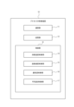
- FIG. 8 is a diagram illustrating an example of the configuration of a process control device according to an embodiment of the present disclosure.
- Figure 1 shows basic operation variables and control variables in the blast furnace process (steps in blast furnace operation).
- Control variables are variables that should be controlled in operation, but cannot be directly operated or are difficult to directly operate, and are changed via correlated operation variables.
- the pulverized coal ratio, blast moisture, etc. are mainly operated to set the molten iron temperature to a target value.
- the pulverized coal ratio, blast moisture, coke ratio, blast flow rate, etc. are mainly operated.
- the blast flow rate is mainly operated to set the iron-making rate to a target value.
- the furnace pressure loss which has a direct effect on blow-through, is used as the air permeability.
- the furnace pressure loss is the difference between the blast pressure and the furnace top pressure (pressure at the furnace top).
- various indices of permeability such as air resistance and opposing shaft differential pressure. Therefore, instead of the furnace pressure loss, another index of permeability may be used as the permeability, or a combination of multiple indexes of permeability may be used.
- the pulverized coal ratio and blast moisture which are operation variables for controlling the molten iron temperature
- optimal operation amounts for the pulverized coal ratio and blast moisture are determined so as to reduce the reducing agent ratio while controlling the molten iron temperature.
- attention is paid to the relationship between the pulverized coal ratio, blast moisture, and blast temperature, and operation amounts are determined for the combination of these.
- FIG. 2 is a diagram showing the process of the process control method according to this embodiment.
- cascade control described in Reference 1 (JP Patent No. 7107444) is used.
- control for calculating a target pulverized coal ratio (PCR) molten iron temperature control in FIG. 2
- control for calculating the pulverized coal flow rate required for the target PCR PCR tracking control in FIG. 2 are performed consecutively.
- a target molten iron temperature which is a target value of the molten iron temperature (HMT)
- the target PCR can be calculated using a physical model described later.
- the molten iron temperature control not only calculates the target PCR (not only determines the manipulated variable of the pulverized coal ratio), but also calculates the manipulated variable of the blast moisture.
- the process control method also includes ironmaking rate control and permeability control.
- the ironmaking rate control acquires a target ironmaking rate, which is a target value of the ironmaking rate (Prod), and calculates the operation amount of the blast flow rate (BV) using a physical model described below.
- the permeability control acquires an upper limit of the furnace pressure drop, which is an upper limit of the furnace pressure drop ( ⁇ P), and calculates the operation amounts of the blast flow rate and the coke ratio using a physical model described below.
- the actual values (which may be observed values or calculated values) in the plant including the blast furnace may be fed back for updating the physical models used in each control.
- PCR pulverized coal ratio
- HMT molten iron temperature
- ⁇ P furnace pressure drop
- Prod ironmaking rate
- individual controllers molten iron temperature control, aeration control, iron-making speed control
- HMT molten iron temperature
- ⁇ P furnace pressure drop
- Prod iron-making speed
- the molten iron temperature is controlled by manipulating the blast moisture and cascade control manipulating the pulverized coal ratio (PCR) and pulverized coal flow rate.
- PCR pulverized coal ratio
- the aeration is controlled by manipulating the blast flow rate and coke ratio.
- the iron-making speed is controlled by manipulating the blast flow rate.
- the blast flow rate is manipulated in the iron-making speed control, the change in the blast flow rate affects the molten iron temperature.
- a physical model of the blast furnace based on reaction kinetics is used to predict future hot metal temperature and hot metal making rate.
- the amount of change in the pulverized coal ratio and the blast moisture is determined so that the predicted value approaches the target value.
- the increase or decrease in the reducing agent ratio can be determined to be either a decrease or an increase depending on the intention.
- the intention is the policy in operation.
- the reducing agent ratio may be decreased.
- the reducing agent ratio may be increased. Examples of external requests include requests due to restrictions on the amount of power supply and restrictions on the amount of raw material inventory.
- the orientation includes a first orientation that prioritizes reducing the reducing agent ratio, and a second orientation that temporarily increases the exhaust gas from the blast furnace.
- the first orientation orientation toward a low reducing agent ratio
- the method disclosed herein can also be applied to, for example, the second orientation (orientation toward a temporary increase in exhaust gas).
- the process control method if the absolute value of the difference between the predicted value and the target value is less than a predetermined threshold, the predicted value is determined to be close to the target value, and the manipulated variables of the two parameters according to the inclination are determined while maintaining the predicted value.
- the process flow in the process control method according to this embodiment is outlined in steps 1 to 4 below.
- Step 1 the future molten iron temperature is predicted using a physical model.
- Step 1 is a response prediction step.
- a predicted value of the future molten iron temperature is obtained based on a predicted value of the future molten iron temperature when the current operating variables are held using a physical model, and a predicted value of the molten iron temperature when the current operating variables are changed.
- the predicted value of the future molten iron temperature when the current operating variables are held is a free response, which will be described later.
- the predicted value of the molten iron temperature when the current operating variables are changed is a step response, which will be described later in this embodiment, but is not limited to this.
- step 2 the manipulated variables are manipulated using quadratic programming so that the predicted value of the molten iron temperature in step 1 matches the target value and the reducing agent ratio is minimized.
- Step 2 is part of the manipulated variable determination step, in which the deviation between the predicted value and the target value is found, the manipulated variables to eliminate the deviation are found, and the manipulated variables are adjusted.
- the manipulated variables are the pulverized coal ratio and the blast moisture.
- the blast flow rate may be manipulated so that the predicted value of the iron-making rate matches the target value, and at least the coke ratio may be manipulated so that the predicted value of the air permeability is equal to or less than the upper limit.
- the air permeability is the pressure loss inside the furnace, and if the predicted value of the pressure loss inside the furnace exceeds the set upper limit, the air permeability state is determined to be abnormal. If the air permeability state is determined to be abnormal, an operation to increase the coke ratio may be executed.
- an operation to decrease the coke ratio may be executed.
- the manipulation of the blast flow rate and coke ratio in step 3 is a disturbance to the molten iron temperature control.
- step 4 when the predicted value of the molten iron temperature in step 1 is approximately equal to the target value, an operation amount is determined that can maintain the predicted value and is a set of two parameters among the pulverized coal ratio, blast moisture, and blast temperature according to the orientation.
- the blast temperature is the temperature of the blast air and is one of the operation variables.
- the fact that the predicted value of the molten iron temperature is approximately equal to the target value may be determined by the absolute value of the difference between the predicted value of the molten iron temperature and the target value being less than a predetermined threshold value.
- the predetermined threshold value may be determined in advance based on past performance data, etc.
- the orientation includes, for example, a first orientation (orientation toward a low reducing agent ratio) and a second orientation (orientation toward a temporary increase in exhaust gas).
- first orientation orientation toward a low reducing agent ratio
- second orientation orientation toward a temporary increase in exhaust gas.
- the operation amount is determined so that the blast moisture is also reduced in combination with the pulverized coal ratio reduction operation.
- the pulverized coal ratio reduction operation reduces the molten iron temperature and permeability.
- the blast moisture reduction operation increases the molten iron temperature and permeability, so the effects of each are offset.
- Figure 3 shows the effects of the pulverized coal ratio, blast moisture, and blast temperature on the inside of the furnace.
- An increase operation is an operation that increases the value of the manipulated variable.
- a decrease operation is an operation that decreases the value of the manipulated variable. As shown above, for example, by simultaneously performing decrease operations on the pulverized coal ratio and blast moisture, it is possible to maintain the predicted molten iron temperature and continue stable operation.
- the operation amount when the orientation is the first orientation (orientation toward a low reducing agent ratio), the operation amount may be determined to be a combination of an operation to reduce the pulverized coal ratio and an operation to reduce the blast moisture. At this time, the effects of each on the molten iron temperature and the air permeability are offset.
- the combination is not limited to this, and when the orientation is the first orientation, the operation amount may be determined to be a combination of an operation to reduce the pulverized coal ratio and an operation to increase the blast temperature, or an operation to reduce the blast temperature and an operation to reduce the blast moisture.
- the operation amount may be determined to be a combination of increasing the pulverized coal ratio and increasing the blast moisture.
- the combination is not limited to this, and in the case of the second tendency, the operation amount may be determined to be a combination of increasing the pulverized coal ratio and decreasing the blast temperature, or increasing the blast temperature and increasing the blast moisture.
- Whether the operation orientation is the first orientation or the second orientation may be determined in advance, or the control unit 13 described below may receive an input to specify the orientation.
- the manipulated variables are changed to maintain the predicted value of the molten iron temperature (to offset the effect), but the amount of change is not unlimited.
- the trend is the first trend and the predicted value of the molten iron temperature is almost the same as the target value
- the pulverized coal ratio and blast moisture cannot be decreased indefinitely.
- the trend is the second trend and the predicted value of the molten iron temperature is almost the same as the target value
- the pulverized coal ratio and blast moisture cannot be increased indefinitely.
- the theoretical combustion temperature (calculated combustion temperature) at which the pulverized coal and blast moisture are blown in must be within a predetermined range (control value). If the theoretical combustion temperature deviates from the control value, various operational problems may occur.
- the control value of the theoretical combustion temperature can be calculated using various known calculation formulas, but may be 2000°C to 2500°C as an example. When calculating the manipulated variable, it is preferable to take the theoretical combustion temperature into consideration.
- the calculations of steps 1 to 4 are explained in detail below.
- the physical model used in this disclosure is similar to the method described in Reference 2 (Hadano Michiharu et al., "Study of Blast Furnace Burn-in Operation Using a Non-Steady-State Model,” Tetsu-to-Haganen, vol. 68, p. 2369). That is, a physical model is used that is capable of calculating the state inside the blast furnace (inside the furnace) in a non-steady state, and is composed of a group of partial differential equations that take into account physical phenomena such as the reduction of ore, heat exchange between the ore and coke, and melting of ore. This physical model may be referred to below as the non-steady-state model.
- the main input variables given to the unsteady model that change over time are the blast flow rate, blast oxygen flow rate, pulverized coal flow rate, blast moisture, blast temperature, coke ratio, and top pressure.
- These input variables are the operational variables or operating factors of the blast furnace.
- the blast flow rate, blast oxygen flow rate, and pulverized coal flow rate are the flow rates of air, oxygen, and pulverized coal sent to the blast furnace, respectively.
- the blast moisture is the humidity of the air sent to the blast furnace.
- the blast temperature is the temperature of the air sent to the blast furnace.
- the coke ratio is the coke ratio at the top of the furnace, and is the weight of coke used per ton of molten iron produced.
- the main output variables of the unsteady model are the gas utilization rate, the amount of solution loss carbon, the reducing agent ratio, the iron-making rate, the molten iron temperature, and the pressure loss in the furnace.
- the unsteady model can be used to calculate the ever-changing molten iron temperature, the iron-making rate, and the pressure loss in the furnace.
- the calculation time interval is not particularly limited, but is 30 minutes in this embodiment.
- the time difference between "t+1" and "t" in the equation for the unsteady model described below is 30 minutes in this embodiment.
- the unsteady model can be expressed by the following equations (1) and (2).
- x(t) is a state variable calculated in the unsteady model.
- the state variables are, for example, the temperature of the coke, the temperature of the iron, the oxidation degree of the ore, the descending speed of the raw material, etc.
- y(t) is the control variable, which is the molten iron temperature, the iron-making speed, and the permeability (furnace pressure loss).
- u(t) is the above-mentioned input variable, which is a variable that can be manipulated by an operator who operates the blast furnace.
- the input variables are the blast flow rate BV(t), the blast oxygen flow rate BVO(t), the pulverized coal flow rate PCI(t), the blast moisture BM(t), the blast temperature BT(t), the coke ratio CR(t), and the furnace top pressure TGP(t).
- u(t) (BV(t), BVO(t), PCI(t), BM(t), BT(t), CR(t), TGP(t)) T.
- PCR pulverized coal ratio
- BM blast moisture
- the future hot metal temperature may be approximated by superposing the free response yf (t) and the step response.
- the predicted value of the hot metal temperature every two hours up to 10 hours ahead, ypre (t), is given by the following equation (5).
- S PCR (t) is the amount of change in molten iron temperature when the pulverized coal ratio (PCR) is operated by a unit amount (1 [kg/t]).
- S BM (t) is the amount of change in blast moisture (BM) when the blast moisture is operated by a unit amount (1 [g/Nm 3 ]).
- S PCR and S BM can be obtained, for example, by another physical model or a step response test in actual operation. In the calculations in this disclosure, the simulation results described in Reference 3 (Y. Hashimoto, Online prediction of hot metal temperature using transient model and moving horizon estimation. ISIJ Int. 2019, vol. 59, p. 1534) were used.
- equation (5) is expressed as the following equation (6) using the step response matrix S
- the deviation between the predicted value of the molten iron temperature and the target value y pre (t) is as shown in equation (7).
- the deviation of the free response y f (t) from the target value y pre (t) is represented as ⁇ y.
- the square of the deviation between the predicted value of the molten iron temperature and the target value y pre (t) is given by the following equation (8).
- the evaluation function J used in the quadratic programming method includes a term for reducing blast moisture (third term) in addition to the first and second terms of equation (8), as shown in equation (9).
- the evaluation function J also includes a fourth term to suppress excessive operation.
- a and R are coefficients. Comparing the responsiveness of the molten iron temperature to changes in the pulverized coal ratio (PCR) and blast moisture (BM), it is known that blast moisture has a more immediate response. However, in order to ensure that the blast moisture can be increased or decreased in an operable range, it is necessary to increase the average blast moisture. If the average blast moisture is increased, heat is absorbed due to the steam decomposition reaction of the blast moisture, and a problem arises in that more reducing material must be added to compensate for the heat loss due to the heat absorption.
- a third term is introduced, and the weighting of ⁇ PCR and ⁇ BM included in vector ⁇ can be changed depending on the size of the elements of coefficient vector a, and the manipulation distribution between the two can be adjusted.
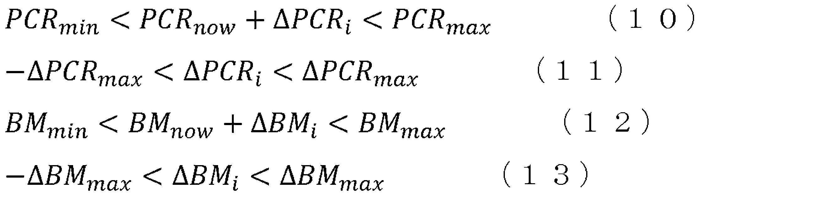
- ⁇ is determined using equation (9) under the constraints of equations (10) to (13) below.
- PCR max and PCR min are the upper and lower limits of the target range of the pulverized coal ratio (PCR), respectively.
- ⁇ PCR max is the upper limit of the magnitude of the allowable change in the pulverized coal ratio (PCR).
- BM max and BM min are the upper and lower limits of the target range of the blast moisture (BM), respectively.
- ⁇ BM max is the upper limit of the magnitude of the allowable change in the blast moisture (BM).
- the unknown variable ⁇ is determined using quadratic programming so as to minimize the evaluation function J, which is a quadratic function for the unknown variable ⁇ .
- the control for determining the unknown variable ⁇ using equation (9) corresponds to the molten iron temperature control in FIG.
- the evaluation function J is designed to reduce the blast moisture in order to reduce the reducing agent ratio, but the same effect can be obtained by using an evaluation function J that directly reduces the reducing agent ratio, for example by giving a penalty to an increase in the pulverized coal ratio.
- the unknown variable ⁇ is obtained when the evaluation function J is minimized, but the evaluation function J may be designed so that the minimization of the deviation between the predicted value and the target value of the molten iron temperature and the reducing agent ratio (or blast moisture) corresponds to the maximization of the evaluation function J.
- the operation amounts of the pulverized coal ratio and the blast moisture may be obtained so that the evaluation function J is minimized or maximized.
- the manipulated variables are manipulated using the following method in addition to the control variables other than the molten iron temperature (iron-making rate and furnace pressure loss).
- ⁇ BV which is the manipulated variable for the blast flow rate (BV) [Nm 3 /min]
- equation (14) is calculated by the following equation (14) so as to eliminate the deviation between the target value and the predicted value.
- Prod(t+T) is the predicted value of the iron-making rate T steps ahead.
- T may be 4, which means the predicted value for 2 hours (30 minutes x 4) ahead.
- Prod ref is the target iron-making rate (target value of the iron-making rate).
- S BV is the amount of change in the iron-making rate when the blast flow rate (BV) is changed by a unit amount (1 [Nm 3 /min]). S BV can be obtained by another physical model or a step response test in actual operation.
- b is a coefficient and is a positive number.
- the control to obtain ⁇ BV according to equation (14) corresponds to the iron-making rate control in FIG. 2.
- Furnace pressure loss ( ⁇ P) is compared with the upper limit (threshold value) to determine the operation amounts of the coke rate (CR) and the blast flow rate (BV).
- the furnace pressure loss ( ⁇ P) exceeds the upper limit, the operation amounts are determined to increase the coke rate and simultaneously decrease the blast flow rate. This corresponds to the operation of stabilizing the lowering of raw materials in the operation of a blast furnace.
- the furnace pressure loss is equal to or less than the upper limit
- the operation amount is determined to gradually decrease the coke rate. In principle, control is performed so that the furnace pressure loss does not exceed the upper limit, but when the furnace pressure loss is equal to or less than the upper limit, it is possible to reduce the operating cost by gradually decreasing the coke rate.
- Figure 5 shows the results of a simulation using the above process control, assuming that the absolute value of the difference between the predicted value of the molten iron temperature obtained in the response prediction step and the target value is equal to or greater than a predetermined threshold value.
- the blast moisture (BM), pulverized coal ratio (PCR), blast flow rate (BV), and coke ratio (CR) were manipulated based on predicted values using a non-steady-state model of the molten iron temperature (HMT), iron-making rate (Prod), and furnace pressure drop ( ⁇ P), which is an example of permeability.
- the target molten iron temperature was 1500°C.
- the target iron-making rate was 7 t/min.
- the upper limit of furnace pressure drop was 100 kPa.
- the hot metal temperature (HMT) is controlled to be close to the target value, and based on the evaluation function J shown in equation (9), the blast moisture (BM) is kept close to the lower limit while suppressing the variation in the hot metal temperature. Having the blast moisture close to the lower limit leads to a reduction in the reducing agent rate, as heat absorption due to the steam decomposition reaction, which requires the addition of reducing agent, is less likely to occur.
- the pig iron making rate (Prod) is controlled to be close to the target value, and the furnace pressure loss ( ⁇ P) is also kept below the upper limit.
- FIG. 6 is a diagram showing the results of a simulation performed by the control of the comparative example.
- the pulverized coal ratio (PCR), the blast flow rate (BV), and the coke ratio (CR) were manipulated based on the predicted values using a non-steady model of the hot metal temperature (HMT), the iron-making rate (Prod), and the furnace pressure drop ( ⁇ P), which is an example of permeability.
- the simulation conditions were the same as those in FIG. 5, except for the blast moisture (BM).
- the blast moisture was set to a constant value of 15.5 [g/Nm 3 ].
- the average value of the reducing agent ratio in the process control method according to the present embodiment was reduced compared to the average value of the reducing agent ratio in the comparative example.
- the amount of oxygen (oxygen consumption rate) [Nm 3 /t] blown from the tuyere required to produce 1 t of hot metal is reduced. Therefore, the target iron-making speed can be achieved with a smaller blast flow rate. As a result, there is a margin for pressure loss, and the coke rate can be reduced (see CR in Figures 5 and 6).
- Figure 7 shows an example of the results when the manipulated variable is calculated by combining two manipulated variables, assuming that the absolute value of the difference between the predicted value of the molten iron temperature obtained in the response prediction step and the target value is less than a predetermined threshold. Items such as BV and Prod are the same as in Figure 5. The horizontal axis is also a common time axis. The example in Figure 7 shows changes over a 12-hour period. As shown by the dashed circles for the pulverized coal ratio (PCR) and blast moisture (BM), the manipulated variable changes with a combination of lowering the pulverized coal ratio and lowering the blast moisture. However, even with this change, no significant change is seen in the molten iron temperature (HMT). In other words, it is possible to maintain the molten iron temperature and continue stable operation while changing the reducing agent ratio according to the intention.
- PCR pulverized coal ratio
- BM blast moisture
- FIG. 8 is a diagram showing an example of the configuration of a process control device 10 according to one embodiment.
- the process control device 10 includes a communication unit 11, a memory unit 12, and a control unit 13.
- the control unit 13 includes a molten iron temperature control unit 14, an iron-making speed control unit 15, a permeability control unit 16, and a PCR tracking control unit 17.
- the process control device 10 executes the above-mentioned process control method.
- the process control device 10 may display information such as the operation amount on a display unit such as a liquid crystal display.
- the communication unit 11 includes a communication module for communicating with a higher-level system.
- the higher-level system includes a process computer that manages processes in a plant including a blast furnace.
- the communication unit 11 may include a communication module that supports mobile communication standards such as 4G (4th Generation) and 5G (5th Generation).
- the communication unit 11 may include a communication module that supports wired or wireless LAN standards.
- the control unit 13 can acquire information such as the target molten iron temperature, the target iron-making speed, and the upper limit of pressure loss in the furnace from the higher-level system via the communication unit 11.
- the control unit 13 can also output information on the operation variables that have been operated, i.e., the operation variables that reflect the calculated operation amount, to the higher-level system via the communication unit 11.
- the storage unit 12 stores the above physical model.
- the storage unit 12 also stores programs and data related to the control of the blast furnace process.
- the storage unit 12 may include any storage device, such as a semiconductor storage device, an optical storage device, and a magnetic storage device.
- the semiconductor storage device may include, for example, a semiconductor memory.
- the storage unit 12 may include multiple types of storage devices.
- the control unit 13 controls and manages each functional unit constituting the process control device 10 and the entire process control device 10.
- the control unit 13 may also acquire data used for control. That is, the control unit 13 may acquire the molten iron temperature, iron-making speed, and permeability of the blast furnace by observed or calculated values.
- the control unit 13 is configured to include at least one processor, such as a CPU (Central Processing Unit), in order to control and manage various functions.
- the control unit 13 may be configured with one processor or multiple processors.
- the processor constituting the control unit 13 may function as the molten iron temperature control unit 14, iron-making speed control unit 15, permeability control unit 16, and PCR tracking control unit 17 by reading and executing a program from the memory unit 12.
- the molten iron temperature control unit 14 acquires the target molten iron temperature, which is the target value for the molten iron temperature, and calculates the operation amounts of the blast moisture and the pulverized coal ratio so that the molten iron temperature becomes the target molten iron temperature when the absolute value of the difference between the predicted value and the target value of the molten iron temperature is equal to or greater than a predetermined threshold value.
- the molten iron temperature control unit 14 is a functional unit that executes the "molten iron temperature control" in FIG. 2.
- the molten iron temperature control unit 14 combines two of the pulverized coal ratio, blast moisture, and blast temperature to determine the operation amounts so as to maintain the predicted value.
- the iron-making speed control unit 15 acquires the target iron-making speed, which is the target value of the iron-making speed, and calculates the operation amount of the blast flow rate so that the iron-making speed becomes the target iron-making speed.
- the iron-making speed control unit 15 is a functional unit that executes the "iron-making speed control" in FIG. 2.
- the air permeability control unit 16 acquires the upper limit of the air permeability (inner furnace pressure loss in this embodiment) and calculates at least the manipulated variable of the coke ratio so that the air permeability does not exceed the upper limit.
- the air permeability control unit 16 may further calculate the manipulated variable of the blast flow rate, as in this embodiment.
- the air permeability control unit 16 is a functional unit that executes the "air permeability control" in FIG. 2.
- the PCR tracking control unit 17 acquires the pulverized coal ratio (target PCR), which is the target value set by the molten iron temperature control unit 14, and calculates the manipulated variable of the pulverized coal flow rate (PCI) so as to track the target PCR through PCR tracking control.
- target PCR pulverized coal ratio
- PCI pulverized coal flow rate
- the molten iron temperature control unit 14, the iron-making speed control unit 15, and the permeability control unit 16 are individual controllers for controlling the molten iron temperature (HMT), the iron-making speed (Prod), and the furnace pressure drop ( ⁇ P), respectively.
- the molten iron temperature control unit 14 executes step 1 (response prediction step) using a physical model to obtain a predicted value of the molten iron temperature.
- the molten iron temperature control unit 14 executes step 2 (part of the operation amount determination step) to obtain the operation amounts of the pulverized coal ratio and the blast moisture.
- the iron-making speed control unit 15 executes step 3 to obtain the operation amount of the blast flow rate so as to eliminate the deviation between the target value and the predicted value of the iron-making speed.
- the permeability control unit 16 executes step 3 to obtain the operation amounts of the blast flow rate and the coke ratio so as to prevent the predicted value of the furnace pressure drop from exceeding the upper limit.
- the molten iron temperature control unit 14 executes step 4 (part of the operation amount determination step) to determine the operation amount for an appropriate combination of two of the pulverized coal ratio, blast moisture, and blast temperature according to the preference.
- the molten iron temperature control unit 14, the iron-making speed control unit 15, and the air permeability control unit 16, which are constructed as individual controllers, are control systems with disturbance removal characteristics that absorb fluctuations based on the operation of the operation variables by other control units by operating their own operation variables. Therefore, the molten iron temperature control unit 14, the iron-making speed control unit 15, and the air permeability control unit 16 can reduce the influence of interference of the operation variables from other control units.
- a process control method executed by the process control device 10 may be used as part of a blast furnace operation method.
- the operating variables manipulated in the above-mentioned process control method may be used to change the operating conditions in the operation of the blast furnace.
- such a blast furnace operation method may be executed as part of a manufacturing method for producing molten pig iron.
- raw iron ore is melted and reduced to become pig iron, which is then tapped as molten pig iron, and the blast furnace may be operated according to this operating method.
- the operating amount determined by the molten pig iron temperature control unit 14 may be displayed on a display device or the like as a proposal for a reducing agent ratio according to the operation orientation, and communicated to an operator.
- the process control device 10 may be realized, for example, by a computer separate from the process computer that controls the operation of the blast furnace, or may be realized by the process computer.
- the computer includes, for example, a memory and a hard disk drive (storage device), a CPU (processing device), and a display device such as a display.
- Various functions can be realized by organic cooperation between hardware such as the CPU and memory and programs.
- the memory unit 12 may be realized, for example, by a storage device.
- the control unit 13 may be realized, for example, by a CPU.
- the process control method, blast furnace operation method, molten iron production method, process control device 10, and program according to this embodiment realizes the proposal of reducing agent ratios according to the customer's wishes while suppressing variation in molten iron temperature and maintaining stable operation.
- the configuration of the process control device 10 shown in FIG. 8 is one example.
- the process control device 10 does not need to include all of the components shown in FIG. 8.
- the process control device 10 may include components other than those shown in FIG. 8.
- the process control device 10 may be configured to further include a display unit.
Landscapes
- Engineering & Computer Science (AREA)
- Chemical & Material Sciences (AREA)
- Manufacturing & Machinery (AREA)
- Materials Engineering (AREA)
- Metallurgy (AREA)
- Organic Chemistry (AREA)
- Manufacture Of Iron (AREA)
- Feedback Control In General (AREA)
- Manufacture And Refinement Of Metals (AREA)
- Waste-Gas Treatment And Other Accessory Devices For Furnaces (AREA)
Abstract
Description
高炉の内部の状態を計算可能な物理モデルを用いて将来の溶銑温度の予測値を求める応答予測ステップと、
前記応答予測ステップで求められた前記溶銑温度の予測値と目標値との差分の絶対値が所定の閾値以上の場合に、前記溶銑温度の予測値と目標値との偏差を求めて、前記偏差に対応する項と還元材比又は送風湿分を低減するための項とを有する評価関数が最小化又は最大化するように、微粉炭比及び送風湿分の操作量を求め、
前記絶対値が前記所定の閾値未満の場合に、志向に応じて、前記微粉炭比、前記送風湿分及び送風温度のうちの2つを組み合わせて、前記予測値を維持するように操作量を求める、操作量決定ステップと、を含む。
前記志向は、前記還元材比の低減を優先する第1志向と、一時的に前記高炉の排ガスを増加させる第2志向と、を含む。
前記操作量決定ステップは、
前記志向が前記第1志向の場合に、前記微粉炭比の下げ操作と前記送風湿分の下げ操作、前記微粉炭比の下げ操作と前記送風温度の上げ操作又は前記送風温度の下げ操作と前記送風湿分の下げ操作の組み合わせとなるように操作量を求め、
前記志向が前記第2志向の場合に、前記微粉炭比の上げ操作と前記送風湿分の上げ操作、前記微粉炭比の上げ操作と前記送風温度の下げ操作又は前記送風温度の上げ操作と前記送風湿分の上げ操作の組み合わせとなるように操作量を求める。
理論燃焼温度が予め定められた所定の範囲内の温度になるように、前記微粉炭比、前記送風湿分及び送風温度のうちの2つの組み合わせにおける操作量を求める。
前記応答予測ステップは、前記物理モデルを用いて現在の操作変数が保持された場合の将来の溶銑温度の予測値と現在の操作変数を変化させた場合の溶銑温度の予測値とに基づいて将来の前記溶銑温度の予測値を求める。
前記操作量決定ステップは、求める前記微粉炭比及び前記送風湿分の操作量を未知変数として、前記未知変数に関する一次式の制約条件下で、前記未知変数に関する二次関数である前記評価関数を用いて、前記未知変数を決定する。
造銑速度の予測値が目標値と合致するように送風流量を操作し、通気度の予測値が上限以下となるようにコークス比を操作するステップをさらに含む。
(1)から(7)のいずれかのプロセスの制御方法によって操作された操作変数を用いて操業条件を変更する。
(8)の高炉の操業方法によって操業される前記高炉を用いて溶銑を製造する。
高炉の内部の状態を計算可能な物理モデルを記憶する記憶部と、
溶銑温度の目標値である目標溶銑温度を取得して、前記溶銑温度が前記目標溶銑温度となるように、微粉炭比及び送風湿分の操作量を算出する溶銑温度制御部と、を備え、
前記溶銑温度制御部は、
前記物理モデルを用いて将来の溶銑温度の予測値を求め、
前記溶銑温度の予測値と目標値との差分の絶対値が所定の閾値以上の場合に、前記溶銑温度の予測値と目標値との偏差を求めて、前記偏差に対応する項と還元材比又は送風湿分を低減するための項とを有する評価関数が最小化又は最大化するように、微粉炭比及び送風湿分の操作量を求め、
前記絶対値が前記所定の閾値未満の場合に、志向に応じて、前記微粉炭比、前記送風湿分及び送風温度のうちの2つを組み合わせて、前記予測値を維持するように操作量を求める。
コンピュータに、
高炉の内部の状態を計算可能な物理モデルを用いて将来の溶銑温度の予測値を求める応答予測ステップと、
前記応答予測ステップで求められた前記溶銑温度の予測値と目標値との差分の絶対値が所定の閾値以上の場合に、前記溶銑温度の予測値と目標値との偏差を求めて、前記偏差に対応する項と還元材比又は送風湿分を低減するための項とを有する評価関数が最小化又は最大化するように、微粉炭比及び送風湿分の操作量を求め、
前記絶対値が前記所定の閾値未満の場合に、志向に応じて、前記微粉炭比、前記送風湿分及び送風温度のうちの2つを組み合わせて、前記予測値を維持するように操作量を求める、操作量決定ステップと、を実行させる。






11 通信部
12 記憶部
13 制御部
14 溶銑温度制御部
15 造銑速度制御部
16 通気度制御部
17 PCR追従制御部
Claims (11)
- 高炉の内部の状態を計算可能な物理モデルを用いて将来の溶銑温度の予測値を求める応答予測ステップと、
前記応答予測ステップで求められた前記溶銑温度の予測値と目標値との差分の絶対値が所定の閾値以上の場合に、前記溶銑温度の予測値と目標値との偏差を求めて、前記偏差に対応する項と還元材比又は送風湿分を低減するための項とを有する評価関数が最小化又は最大化するように、微粉炭比及び送風湿分の操作量を求め、
前記絶対値が前記所定の閾値未満の場合に、志向に応じて、前記微粉炭比、前記送風湿分及び送風温度のうちの2つを組み合わせて、前記予測値を維持するように操作量を求める、操作量決定ステップと、を含む、プロセスの制御方法。 - 前記志向は、前記還元材比の低減を優先する第1志向と、一時的に前記高炉の排ガスを増加させる第2志向と、を含む、請求項1に記載のプロセスの制御方法。
- 前記操作量決定ステップは、
前記志向が前記第1志向の場合に、前記微粉炭比の下げ操作と前記送風湿分の下げ操作、前記微粉炭比の下げ操作と前記送風温度の上げ操作又は前記送風温度の下げ操作と前記送風湿分の下げ操作の組み合わせとなるように操作量を求め、
前記志向が前記第2志向の場合に、前記微粉炭比の上げ操作と前記送風湿分の上げ操作、前記微粉炭比の上げ操作と前記送風温度の下げ操作又は前記送風温度の上げ操作と前記送風湿分の上げ操作の組み合わせとなるように操作量を求める、請求項2に記載のプロセスの制御方法。 - 理論燃焼温度が予め定められた所定の範囲内の温度になるように、前記微粉炭比、前記送風湿分及び送風温度のうちの2つの組み合わせにおける操作量を求める、請求項3に記載のプロセスの制御方法。
- 前記応答予測ステップは、前記物理モデルを用いて現在の操作変数が保持された場合の将来の溶銑温度の予測値と現在の操作変数を変化させた場合の溶銑温度の予測値とに基づいて将来の前記溶銑温度の予測値を求める、請求項1から4のいずれか一項に記載のプロセスの制御方法。
- 前記操作量決定ステップは、求める前記微粉炭比及び前記送風湿分の操作量を未知変数として、前記未知変数に関する一次式の制約条件下で、前記未知変数に関する二次関数である前記評価関数を用いて、前記未知変数を決定する、請求項1から5のいずれか一項に記載のプロセスの制御方法。
- 造銑速度の予測値が目標値と合致するように送風流量を操作し、通気度の予測値が上限以下となるようにコークス比を操作するステップをさらに含む、請求項1から6のいずれか一項に記載のプロセスの制御方法。
- 請求項1から7のいずれか一項に記載のプロセスの制御方法によって操作された操作変数を用いて操業条件を変更する、高炉の操業方法。
- 請求項8に記載の高炉の操業方法によって操業される前記高炉を用いて溶銑を製造する、溶銑の製造方法。
- 高炉の内部の状態を計算可能な物理モデルを記憶する記憶部と、
溶銑温度の目標値である目標溶銑温度を取得して、前記溶銑温度が前記目標溶銑温度となるように、微粉炭比及び送風湿分の操作量を算出する溶銑温度制御部と、を備え、
前記溶銑温度制御部は、
前記物理モデルを用いて将来の溶銑温度の予測値を求め、
前記溶銑温度の予測値と目標値との差分の絶対値が所定の閾値以上の場合に、前記溶銑温度の予測値と目標値との偏差を求めて、前記偏差に対応する項と還元材比又は送風湿分を低減するための項とを有する評価関数が最小化又は最大化するように、微粉炭比及び送風湿分の操作量を求め、
前記絶対値が前記所定の閾値未満の場合に、志向に応じて、前記微粉炭比、前記送風湿分及び送風温度のうちの2つを組み合わせて、前記予測値を維持するように操作量を求める、プロセスの制御装置。 - コンピュータに、
高炉の内部の状態を計算可能な物理モデルを用いて将来の溶銑温度の予測値を求める応答予測ステップと、
前記応答予測ステップで求められた前記溶銑温度の予測値と目標値との差分の絶対値が所定の閾値以上の場合に、前記溶銑温度の予測値と目標値との偏差を求めて、前記偏差に対応する項と還元材比又は送風湿分を低減するための項とを有する評価関数が最小化又は最大化するように、微粉炭比及び送風湿分の操作量を求め、
前記絶対値が前記所定の閾値未満の場合に、志向に応じて、前記微粉炭比、前記送風湿分及び送風温度のうちの2つを組み合わせて、前記予測値を維持するように操作量を求める、操作量決定ステップと、を実行させる、プログラム。
Priority Applications (4)
| Application Number | Priority Date | Filing Date | Title |
|---|---|---|---|
| EP23924188.8A EP4628599A4 (en) | 2023-02-21 | 2023-11-21 | Process control method, blast furnace operation method, molten-iron manufacturing method, and process control device and program |
| CN202380092881.1A CN120603961A (zh) | 2023-02-21 | 2023-11-21 | 工艺控制方法、高炉操作方法、铁水制造方法、工艺控制装置及程序 |
| KR1020257021593A KR20250116093A (ko) | 2023-02-21 | 2023-11-21 | 프로세스의 제어 방법, 고로의 조업 방법, 용선의 제조 방법, 프로세스의 제어 장치 및 프로그램 |
| JP2024514456A JP7816497B2 (ja) | 2023-02-21 | 2023-11-21 | プロセスの制御方法、高炉の操業方法、溶銑の製造方法、プロセスの制御装置及びプログラム |
Applications Claiming Priority (2)
| Application Number | Priority Date | Filing Date | Title |
|---|---|---|---|
| JP2023-025623 | 2023-02-21 | ||
| JP2023025623 | 2023-02-21 |
Publications (1)
| Publication Number | Publication Date |
|---|---|
| WO2024176544A1 true WO2024176544A1 (ja) | 2024-08-29 |
Family
ID=92500816
Family Applications (1)
| Application Number | Title | Priority Date | Filing Date |
|---|---|---|---|
| PCT/JP2023/041872 Ceased WO2024176544A1 (ja) | 2023-02-21 | 2023-11-21 | プロセスの制御方法、高炉の操業方法、溶銑の製造方法、プロセスの制御装置及びプログラム |
Country Status (6)
| Country | Link |
|---|---|
| EP (1) | EP4628599A4 (ja) |
| JP (1) | JP7816497B2 (ja) |
| KR (1) | KR20250116093A (ja) |
| CN (1) | CN120603961A (ja) |
| TW (1) | TWI892381B (ja) |
| WO (1) | WO2024176544A1 (ja) |
Citations (5)
| Publication number | Priority date | Publication date | Assignee | Title |
|---|---|---|---|---|
| JPH02250911A (ja) * | 1989-03-23 | 1990-10-08 | Sumitomo Metal Ind Ltd | 高炉の操業方法 |
| JP2000129319A (ja) * | 1998-10-23 | 2000-05-09 | Kawasaki Steel Corp | 高炉炉熱制御方法及び装置 |
| JP2018024935A (ja) * | 2016-08-02 | 2018-02-15 | Jfeスチール株式会社 | 溶銑温度予測方法、溶銑温度予測装置、高炉の操業方法、操業ガイダンス装置、溶銑温度制御方法、及び溶銑温度制御装置 |
| WO2022009621A1 (ja) * | 2020-07-06 | 2022-01-13 | Jfeスチール株式会社 | 操業ガイダンス方法、高炉の操業方法、溶銑の製造方法、操業ガイダンス装置 |
| JP7107444B2 (ja) | 2020-07-06 | 2022-07-27 | Jfeスチール株式会社 | 溶銑温度の制御方法、操業ガイダンス方法、高炉の操業方法、溶銑の製造方法、溶銑温度の制御装置および操業ガイダンス装置 |
Family Cites Families (6)
| Publication number | Priority date | Publication date | Assignee | Title |
|---|---|---|---|---|
| JPH11335710A (ja) | 1998-05-22 | 1999-12-07 | Sumitomo Metal Ind Ltd | 高炉炉熱予測方法 |
| JP6493447B2 (ja) * | 2016-08-02 | 2019-04-03 | Jfeスチール株式会社 | 溶銑温度予測方法、溶銑温度予測装置、高炉の操業方法、操業ガイダンス装置、溶銑温度制御方法、及び溶銑温度制御装置 |
| JP6729514B2 (ja) * | 2017-07-19 | 2020-07-22 | Jfeスチール株式会社 | 溶銑温度予測方法、溶銑温度予測装置、高炉の操業方法、操業ガイダンス装置、溶銑温度制御方法、及び溶銑温度制御装置 |
| JP6930507B2 (ja) * | 2018-08-23 | 2021-09-01 | Jfeスチール株式会社 | 溶銑温度予測方法、溶銑温度予測装置、高炉の操業方法、操業ガイダンス装置、溶銑温度制御方法、及び溶銑温度制御装置 |
| EP3989013B1 (en) * | 2019-07-23 | 2024-02-14 | JFE Steel Corporation | Method for controlling process, operation guidance method, method for operating blast furnace, method for producing hot metal, and device for controlling process |
| CN113832277B (zh) * | 2020-06-23 | 2023-01-20 | 宝山钢铁股份有限公司 | 一种高炉出铁智能判定及自动开口控制方法 |
-
2023
- 2023-11-21 KR KR1020257021593A patent/KR20250116093A/ko active Pending
- 2023-11-21 JP JP2024514456A patent/JP7816497B2/ja active Active
- 2023-11-21 WO PCT/JP2023/041872 patent/WO2024176544A1/ja not_active Ceased
- 2023-11-21 CN CN202380092881.1A patent/CN120603961A/zh active Pending
- 2023-11-21 EP EP23924188.8A patent/EP4628599A4/en active Pending
- 2023-12-25 TW TW112150494A patent/TWI892381B/zh active
Patent Citations (5)
| Publication number | Priority date | Publication date | Assignee | Title |
|---|---|---|---|---|
| JPH02250911A (ja) * | 1989-03-23 | 1990-10-08 | Sumitomo Metal Ind Ltd | 高炉の操業方法 |
| JP2000129319A (ja) * | 1998-10-23 | 2000-05-09 | Kawasaki Steel Corp | 高炉炉熱制御方法及び装置 |
| JP2018024935A (ja) * | 2016-08-02 | 2018-02-15 | Jfeスチール株式会社 | 溶銑温度予測方法、溶銑温度予測装置、高炉の操業方法、操業ガイダンス装置、溶銑温度制御方法、及び溶銑温度制御装置 |
| WO2022009621A1 (ja) * | 2020-07-06 | 2022-01-13 | Jfeスチール株式会社 | 操業ガイダンス方法、高炉の操業方法、溶銑の製造方法、操業ガイダンス装置 |
| JP7107444B2 (ja) | 2020-07-06 | 2022-07-27 | Jfeスチール株式会社 | 溶銑温度の制御方法、操業ガイダンス方法、高炉の操業方法、溶銑の製造方法、溶銑温度の制御装置および操業ガイダンス装置 |
Non-Patent Citations (3)
| Title |
|---|
| ISIJ INT., vol. 59, 2019, pages 1534 |
| MICHIHARU HATANO ET AL.: "Investigation of Blow-in Operation through the Blast Furnace Dynamic Model", TETSU-TO-HAGANE, vol. 68, pages 2369 |
| See also references of EP4628599A1 |
Also Published As
| Publication number | Publication date |
|---|---|
| TW202434743A (zh) | 2024-09-01 |
| EP4628599A4 (en) | 2026-03-04 |
| KR20250116093A (ko) | 2025-07-31 |
| TWI892381B (zh) | 2025-08-01 |
| EP4628599A1 (en) | 2025-10-08 |
| CN120603961A (zh) | 2025-09-05 |
| JP7816497B2 (ja) | 2026-02-18 |
| JPWO2024176544A1 (ja) | 2024-08-29 |
Similar Documents
| Publication | Publication Date | Title |
|---|---|---|
| Hashimoto et al. | Practical operation guidance on thermal control of blast furnace | |
| KR102933531B1 (ko) | 조업 가이던스 방법, 고로의 조업 방법, 용선의 제조 방법, 조업 가이던스 장치 | |
| TWI794865B (zh) | 鐵水溫度之控制方法、作業指導方法、高爐之作業方法、鐵水之製造方法、鐵水溫度之控制裝置以及作業指導裝置 | |
| JP6915754B2 (ja) | プロセスの制御方法、操業ガイダンス方法、高炉の操業方法、溶銑の製造方法およびプロセスの制御装置 | |
| JP2018024935A (ja) | 溶銑温度予測方法、溶銑温度予測装置、高炉の操業方法、操業ガイダンス装置、溶銑温度制御方法、及び溶銑温度制御装置 | |
| JP7264321B1 (ja) | 溶銑温度の予測方法、操業ガイダンス方法、溶銑の製造方法、溶銑温度の予測装置、操業ガイダンス装置、高炉操業ガイダンスシステム、高炉操業ガイダンスサーバ及び端末装置 | |
| WO2021014782A1 (ja) | 学習モデル生成方法、学習モデル生成装置、高炉の溶銑温度制御方法、高炉の溶銑温度制御ガイダンス方法、及び溶銑の製造方法 | |
| JP2023025646A (ja) | 制御装置、方法及びプログラム | |
| JP7687439B2 (ja) | プロセスの制御方法、高炉の操業方法、溶銑の製造方法及びプロセスの制御装置 | |
| JP7816497B2 (ja) | プロセスの制御方法、高炉の操業方法、溶銑の製造方法、プロセスの制御装置及びプログラム | |
| JP7384326B1 (ja) | 高炉の溶銑温度予測方法、高炉の溶銑温度予測モデルの学習方法、高炉の操業方法、高炉の溶銑温度予測装置、高炉の溶銑温度予測システムおよび端末装置 | |
| Xie et al. | Prediction Model of Endpoint Temperature of Converter Steelmaking Based on PCA-BP Neural Network | |
| Zhang et al. | Prediction of blast furnace fuel ratio based on back‐propagation neural network and K‐Nearest neighbor algorithm | |
| CN113961865B (zh) | 一种大型转炉精确控制tsc阶段调温剂加入量的方法 | |
| JP7679812B2 (ja) | プロセスの制御方法、高炉の操業方法、溶銑の製造方法及びプロセスの制御装置 | |
| JPS61508A (ja) | 高炉操業法 | |
| JP7384150B2 (ja) | 操業ガイダンス方法、高炉の操業方法、溶銑の製造方法及び操業ガイダンス装置 | |
| WO2026042473A1 (ja) | プロセスの制御方法、高炉の操業方法及び溶銑の製造方法 | |
| Spirin et al. | Information-simulating system for distribution of hot blast and natural gas through the blast furnace tuyeres | |
| JP7772284B1 (ja) | 溶銑温度制御方法、溶銑温度制御装置、操業ガイダンス方法、高炉の操業方法及び溶銑の製造方法 | |
| WO2025063096A1 (ja) | 製鉄所操業支援方法、操業支援装置、表示装置、及び操業支援プログラム | |
| EP4545661A1 (en) | Sintering process control method, operation guidance method, sintered ore manufacturing method, sintering process control device, operation guidance device, sintering operation guidance system, and terminal device | |
| JP2025183870A (ja) | 造銑速度予測方法、操業ガイダンス方法、溶銑製造方法、及び造銑速度予測装置 | |
| Hui et al. | A Mathematical Model of Burden Distribution in the Blast Furnace Equipped by a Bell-Less Top Charging System | |
| CN119710113A (zh) | 高炉鼓风加湿湿度控制方法、系统、设备及介质 |
Legal Events
| Date | Code | Title | Description |
|---|---|---|---|
| WWE | Wipo information: entry into national phase |
Ref document number: 2024514456 Country of ref document: JP |
|
| 121 | Ep: the epo has been informed by wipo that ep was designated in this application |
Ref document number: 23924188 Country of ref document: EP Kind code of ref document: A1 |
|
| WWE | Wipo information: entry into national phase |
Ref document number: 2023924188 Country of ref document: EP |
|
| ENP | Entry into the national phase |
Ref document number: 2023924188 Country of ref document: EP Effective date: 20250701 |
|
| REG | Reference to national code |
Ref country code: BR Ref legal event code: B01A Ref document number: 112025014115 Country of ref document: BR |
|
| WWE | Wipo information: entry into national phase |
Ref document number: 202517072492 Country of ref document: IN Ref document number: 202380092881.1 Country of ref document: CN |
|
| WWP | Wipo information: published in national office |
Ref document number: 1020257021593 Country of ref document: KR |
|
| WWP | Wipo information: published in national office |
Ref document number: 202380092881.1 Country of ref document: CN Ref document number: 202517072492 Country of ref document: IN |
|
| NENP | Non-entry into the national phase |
Ref country code: DE |
|
| WWP | Wipo information: published in national office |
Ref document number: 2023924188 Country of ref document: EP |
|
| ENP | Entry into the national phase |
Ref document number: 112025014115 Country of ref document: BR Kind code of ref document: A2 Effective date: 20250708 |