WO2024180826A1 - 連続焼鈍設備、連続焼鈍方法、冷延鋼板の製造方法及びめっき鋼板の製造方法 - Google Patents
連続焼鈍設備、連続焼鈍方法、冷延鋼板の製造方法及びめっき鋼板の製造方法 Download PDFInfo
- Publication number
- WO2024180826A1 WO2024180826A1 PCT/JP2023/041124 JP2023041124W WO2024180826A1 WO 2024180826 A1 WO2024180826 A1 WO 2024180826A1 JP 2023041124 W JP2023041124 W JP 2023041124W WO 2024180826 A1 WO2024180826 A1 WO 2024180826A1
- Authority
- WO
- WIPO (PCT)
- Prior art keywords
- steel sheet
- cooling
- induction heating
- continuous annealing
- heating device
- Prior art date
- Legal status (The legal status is an assumption and is not a legal conclusion. Google has not performed a legal analysis and makes no representation as to the accuracy of the status listed.)
- Ceased
Links
Images



Classifications
-
- C—CHEMISTRY; METALLURGY
- C23—COATING METALLIC MATERIAL; COATING MATERIAL WITH METALLIC MATERIAL; CHEMICAL SURFACE TREATMENT; DIFFUSION TREATMENT OF METALLIC MATERIAL; COATING BY VACUUM EVAPORATION, BY SPUTTERING, BY ION IMPLANTATION OR BY CHEMICAL VAPOUR DEPOSITION, IN GENERAL; INHIBITING CORROSION OF METALLIC MATERIAL OR INCRUSTATION IN GENERAL
- C23C—COATING METALLIC MATERIAL; COATING MATERIAL WITH METALLIC MATERIAL; SURFACE TREATMENT OF METALLIC MATERIAL BY DIFFUSION INTO THE SURFACE, BY CHEMICAL CONVERSION OR SUBSTITUTION; COATING BY VACUUM EVAPORATION, BY SPUTTERING, BY ION IMPLANTATION OR BY CHEMICAL VAPOUR DEPOSITION, IN GENERAL
- C23C2/00—Hot-dipping or immersion processes for applying the coating material in the molten state without affecting the shape; Apparatus therefor
- C23C2/04—Hot-dipping or immersion processes for applying the coating material in the molten state without affecting the shape; Apparatus therefor characterised by the coating material
- C23C2/06—Zinc or cadmium or alloys based thereon
-
- C—CHEMISTRY; METALLURGY
- C21—METALLURGY OF IRON
- C21D—MODIFYING THE PHYSICAL STRUCTURE OF FERROUS METALS; GENERAL DEVICES FOR HEAT TREATMENT OF FERROUS OR NON-FERROUS METALS OR ALLOYS; MAKING METAL MALLEABLE, e.g. BY DECARBURISATION OR TEMPERING
- C21D1/00—General methods or devices for heat treatment, e.g. annealing, hardening, quenching or tempering
- C21D1/26—Methods of annealing
-
- C—CHEMISTRY; METALLURGY
- C21—METALLURGY OF IRON
- C21D—MODIFYING THE PHYSICAL STRUCTURE OF FERROUS METALS; GENERAL DEVICES FOR HEAT TREATMENT OF FERROUS OR NON-FERROUS METALS OR ALLOYS; MAKING METAL MALLEABLE, e.g. BY DECARBURISATION OR TEMPERING
- C21D1/00—General methods or devices for heat treatment, e.g. annealing, hardening, quenching or tempering
- C21D1/34—Methods of heating
- C21D1/42—Induction heating
-
- C—CHEMISTRY; METALLURGY
- C21—METALLURGY OF IRON
- C21D—MODIFYING THE PHYSICAL STRUCTURE OF FERROUS METALS; GENERAL DEVICES FOR HEAT TREATMENT OF FERROUS OR NON-FERROUS METALS OR ALLOYS; MAKING METAL MALLEABLE, e.g. BY DECARBURISATION OR TEMPERING
- C21D1/00—General methods or devices for heat treatment, e.g. annealing, hardening, quenching or tempering
- C21D1/56—General methods or devices for heat treatment, e.g. annealing, hardening, quenching or tempering characterised by the quenching agents
- C21D1/613—Gases; Liquefied or solidified normally gaseous material
-
- C—CHEMISTRY; METALLURGY
- C21—METALLURGY OF IRON
- C21D—MODIFYING THE PHYSICAL STRUCTURE OF FERROUS METALS; GENERAL DEVICES FOR HEAT TREATMENT OF FERROUS OR NON-FERROUS METALS OR ALLOYS; MAKING METAL MALLEABLE, e.g. BY DECARBURISATION OR TEMPERING
- C21D1/00—General methods or devices for heat treatment, e.g. annealing, hardening, quenching or tempering
- C21D1/62—Quenching devices
- C21D1/667—Quenching devices for spray quenching
-
- C—CHEMISTRY; METALLURGY
- C21—METALLURGY OF IRON
- C21D—MODIFYING THE PHYSICAL STRUCTURE OF FERROUS METALS; GENERAL DEVICES FOR HEAT TREATMENT OF FERROUS OR NON-FERROUS METALS OR ALLOYS; MAKING METAL MALLEABLE, e.g. BY DECARBURISATION OR TEMPERING
- C21D11/00—Process control or regulation for heat treatments
-
- C—CHEMISTRY; METALLURGY
- C21—METALLURGY OF IRON
- C21D—MODIFYING THE PHYSICAL STRUCTURE OF FERROUS METALS; GENERAL DEVICES FOR HEAT TREATMENT OF FERROUS OR NON-FERROUS METALS OR ALLOYS; MAKING METAL MALLEABLE, e.g. BY DECARBURISATION OR TEMPERING
- C21D11/00—Process control or regulation for heat treatments
- C21D11/005—Process control or regulation for heat treatments for cooling
-
- C—CHEMISTRY; METALLURGY
- C21—METALLURGY OF IRON
- C21D—MODIFYING THE PHYSICAL STRUCTURE OF FERROUS METALS; GENERAL DEVICES FOR HEAT TREATMENT OF FERROUS OR NON-FERROUS METALS OR ALLOYS; MAKING METAL MALLEABLE, e.g. BY DECARBURISATION OR TEMPERING
- C21D9/00—Heat treatment, e.g. annealing, hardening, quenching or tempering, adapted for particular articles; Furnaces therefor
- C21D9/52—Heat treatment, e.g. annealing, hardening, quenching or tempering, adapted for particular articles; Furnaces therefor for wires; for strips ; for rods of unlimited length
- C21D9/54—Furnaces for treating strips or wire
- C21D9/56—Continuous furnaces for strip or wire
- C21D9/573—Continuous furnaces for strip or wire with cooling
-
- C—CHEMISTRY; METALLURGY
- C21—METALLURGY OF IRON
- C21D—MODIFYING THE PHYSICAL STRUCTURE OF FERROUS METALS; GENERAL DEVICES FOR HEAT TREATMENT OF FERROUS OR NON-FERROUS METALS OR ALLOYS; MAKING METAL MALLEABLE, e.g. BY DECARBURISATION OR TEMPERING
- C21D9/00—Heat treatment, e.g. annealing, hardening, quenching or tempering, adapted for particular articles; Furnaces therefor
- C21D9/52—Heat treatment, e.g. annealing, hardening, quenching or tempering, adapted for particular articles; Furnaces therefor for wires; for strips ; for rods of unlimited length
- C21D9/54—Furnaces for treating strips or wire
- C21D9/56—Continuous furnaces for strip or wire
- C21D9/60—Continuous furnaces for strip or wire with induction heating
-
- C—CHEMISTRY; METALLURGY
- C22—METALLURGY; FERROUS OR NON-FERROUS ALLOYS; TREATMENT OF ALLOYS OR NON-FERROUS METALS
- C22C—ALLOYS
- C22C38/00—Ferrous alloys, e.g. steel alloys
-
- C—CHEMISTRY; METALLURGY
- C23—COATING METALLIC MATERIAL; COATING MATERIAL WITH METALLIC MATERIAL; CHEMICAL SURFACE TREATMENT; DIFFUSION TREATMENT OF METALLIC MATERIAL; COATING BY VACUUM EVAPORATION, BY SPUTTERING, BY ION IMPLANTATION OR BY CHEMICAL VAPOUR DEPOSITION, IN GENERAL; INHIBITING CORROSION OF METALLIC MATERIAL OR INCRUSTATION IN GENERAL
- C23C—COATING METALLIC MATERIAL; COATING MATERIAL WITH METALLIC MATERIAL; SURFACE TREATMENT OF METALLIC MATERIAL BY DIFFUSION INTO THE SURFACE, BY CHEMICAL CONVERSION OR SUBSTITUTION; COATING BY VACUUM EVAPORATION, BY SPUTTERING, BY ION IMPLANTATION OR BY CHEMICAL VAPOUR DEPOSITION, IN GENERAL
- C23C2/00—Hot-dipping or immersion processes for applying the coating material in the molten state without affecting the shape; Apparatus therefor
- C23C2/003—Apparatus
-
- C—CHEMISTRY; METALLURGY
- C23—COATING METALLIC MATERIAL; COATING MATERIAL WITH METALLIC MATERIAL; CHEMICAL SURFACE TREATMENT; DIFFUSION TREATMENT OF METALLIC MATERIAL; COATING BY VACUUM EVAPORATION, BY SPUTTERING, BY ION IMPLANTATION OR BY CHEMICAL VAPOUR DEPOSITION, IN GENERAL; INHIBITING CORROSION OF METALLIC MATERIAL OR INCRUSTATION IN GENERAL
- C23C—COATING METALLIC MATERIAL; COATING MATERIAL WITH METALLIC MATERIAL; SURFACE TREATMENT OF METALLIC MATERIAL BY DIFFUSION INTO THE SURFACE, BY CHEMICAL CONVERSION OR SUBSTITUTION; COATING BY VACUUM EVAPORATION, BY SPUTTERING, BY ION IMPLANTATION OR BY CHEMICAL VAPOUR DEPOSITION, IN GENERAL
- C23C2/00—Hot-dipping or immersion processes for applying the coating material in the molten state without affecting the shape; Apparatus therefor
- C23C2/003—Apparatus
- C23C2/0038—Apparatus characterised by the pre-treatment chambers located immediately upstream of the bath or occurring locally before the dipping process
-
- C—CHEMISTRY; METALLURGY
- C23—COATING METALLIC MATERIAL; COATING MATERIAL WITH METALLIC MATERIAL; CHEMICAL SURFACE TREATMENT; DIFFUSION TREATMENT OF METALLIC MATERIAL; COATING BY VACUUM EVAPORATION, BY SPUTTERING, BY ION IMPLANTATION OR BY CHEMICAL VAPOUR DEPOSITION, IN GENERAL; INHIBITING CORROSION OF METALLIC MATERIAL OR INCRUSTATION IN GENERAL
- C23C—COATING METALLIC MATERIAL; COATING MATERIAL WITH METALLIC MATERIAL; SURFACE TREATMENT OF METALLIC MATERIAL BY DIFFUSION INTO THE SURFACE, BY CHEMICAL CONVERSION OR SUBSTITUTION; COATING BY VACUUM EVAPORATION, BY SPUTTERING, BY ION IMPLANTATION OR BY CHEMICAL VAPOUR DEPOSITION, IN GENERAL
- C23C2/00—Hot-dipping or immersion processes for applying the coating material in the molten state without affecting the shape; Apparatus therefor
- C23C2/02—Pretreatment of the material to be coated, e.g. for coating on selected surface areas
- C23C2/022—Pretreatment of the material to be coated, e.g. for coating on selected surface areas by heating
- C23C2/0224—Two or more thermal pretreatments
-
- C—CHEMISTRY; METALLURGY
- C23—COATING METALLIC MATERIAL; COATING MATERIAL WITH METALLIC MATERIAL; CHEMICAL SURFACE TREATMENT; DIFFUSION TREATMENT OF METALLIC MATERIAL; COATING BY VACUUM EVAPORATION, BY SPUTTERING, BY ION IMPLANTATION OR BY CHEMICAL VAPOUR DEPOSITION, IN GENERAL; INHIBITING CORROSION OF METALLIC MATERIAL OR INCRUSTATION IN GENERAL
- C23C—COATING METALLIC MATERIAL; COATING MATERIAL WITH METALLIC MATERIAL; SURFACE TREATMENT OF METALLIC MATERIAL BY DIFFUSION INTO THE SURFACE, BY CHEMICAL CONVERSION OR SUBSTITUTION; COATING BY VACUUM EVAPORATION, BY SPUTTERING, BY ION IMPLANTATION OR BY CHEMICAL VAPOUR DEPOSITION, IN GENERAL
- C23C2/00—Hot-dipping or immersion processes for applying the coating material in the molten state without affecting the shape; Apparatus therefor
- C23C2/26—After-treatment
- C23C2/28—Thermal after-treatment, e.g. treatment in oil bath
-
- C—CHEMISTRY; METALLURGY
- C23—COATING METALLIC MATERIAL; COATING MATERIAL WITH METALLIC MATERIAL; CHEMICAL SURFACE TREATMENT; DIFFUSION TREATMENT OF METALLIC MATERIAL; COATING BY VACUUM EVAPORATION, BY SPUTTERING, BY ION IMPLANTATION OR BY CHEMICAL VAPOUR DEPOSITION, IN GENERAL; INHIBITING CORROSION OF METALLIC MATERIAL OR INCRUSTATION IN GENERAL
- C23C—COATING METALLIC MATERIAL; COATING MATERIAL WITH METALLIC MATERIAL; SURFACE TREATMENT OF METALLIC MATERIAL BY DIFFUSION INTO THE SURFACE, BY CHEMICAL CONVERSION OR SUBSTITUTION; COATING BY VACUUM EVAPORATION, BY SPUTTERING, BY ION IMPLANTATION OR BY CHEMICAL VAPOUR DEPOSITION, IN GENERAL
- C23C2/00—Hot-dipping or immersion processes for applying the coating material in the molten state without affecting the shape; Apparatus therefor
- C23C2/26—After-treatment
- C23C2/28—Thermal after-treatment, e.g. treatment in oil bath
- C23C2/29—Cooling or quenching
-
- C—CHEMISTRY; METALLURGY
- C23—COATING METALLIC MATERIAL; COATING MATERIAL WITH METALLIC MATERIAL; CHEMICAL SURFACE TREATMENT; DIFFUSION TREATMENT OF METALLIC MATERIAL; COATING BY VACUUM EVAPORATION, BY SPUTTERING, BY ION IMPLANTATION OR BY CHEMICAL VAPOUR DEPOSITION, IN GENERAL; INHIBITING CORROSION OF METALLIC MATERIAL OR INCRUSTATION IN GENERAL
- C23C—COATING METALLIC MATERIAL; COATING MATERIAL WITH METALLIC MATERIAL; SURFACE TREATMENT OF METALLIC MATERIAL BY DIFFUSION INTO THE SURFACE, BY CHEMICAL CONVERSION OR SUBSTITUTION; COATING BY VACUUM EVAPORATION, BY SPUTTERING, BY ION IMPLANTATION OR BY CHEMICAL VAPOUR DEPOSITION, IN GENERAL
- C23C2/00—Hot-dipping or immersion processes for applying the coating material in the molten state without affecting the shape; Apparatus therefor
- C23C2/34—Hot-dipping or immersion processes for applying the coating material in the molten state without affecting the shape; Apparatus therefor characterised by the shape of the material to be treated
- C23C2/36—Elongated material
- C23C2/40—Plates; Strips
-
- C—CHEMISTRY; METALLURGY
- C25—ELECTROLYTIC OR ELECTROPHORETIC PROCESSES; APPARATUS THEREFOR
- C25D—PROCESSES FOR THE ELECTROLYTIC OR ELECTROPHORETIC PRODUCTION OF COATINGS; ELECTROFORMING; APPARATUS THEREFOR
- C25D3/00—Electroplating: Baths therefor
- C25D3/02—Electroplating: Baths therefor from solutions
- C25D3/22—Electroplating: Baths therefor from solutions of zinc
-
- H—ELECTRICITY
- H05—ELECTRIC TECHNIQUES NOT OTHERWISE PROVIDED FOR
- H05B—ELECTRIC HEATING; ELECTRIC LIGHT SOURCES NOT OTHERWISE PROVIDED FOR; CIRCUIT ARRANGEMENTS FOR ELECTRIC LIGHT SOURCES, IN GENERAL
- H05B6/00—Heating by electric, magnetic or electromagnetic fields
- H05B6/02—Induction heating
- H05B6/06—Control, e.g. of temperature, of power
-
- H—ELECTRICITY
- H05—ELECTRIC TECHNIQUES NOT OTHERWISE PROVIDED FOR
- H05B—ELECTRIC HEATING; ELECTRIC LIGHT SOURCES NOT OTHERWISE PROVIDED FOR; CIRCUIT ARRANGEMENTS FOR ELECTRIC LIGHT SOURCES, IN GENERAL
- H05B6/00—Heating by electric, magnetic or electromagnetic fields
- H05B6/02—Induction heating
- H05B6/10—Induction heating apparatus, other than furnaces, for specific applications
- H05B6/101—Induction heating apparatus, other than furnaces, for specific applications for local heating of metal pieces
- H05B6/103—Induction heating apparatus, other than furnaces, for specific applications for local heating of metal pieces multiple metal pieces successively being moved close to the inductor
- H05B6/104—Induction heating apparatus, other than furnaces, for specific applications for local heating of metal pieces multiple metal pieces successively being moved close to the inductor metal pieces being elongated like wires or bands
-
- C—CHEMISTRY; METALLURGY
- C21—METALLURGY OF IRON
- C21D—MODIFYING THE PHYSICAL STRUCTURE OF FERROUS METALS; GENERAL DEVICES FOR HEAT TREATMENT OF FERROUS OR NON-FERROUS METALS OR ALLOYS; MAKING METAL MALLEABLE, e.g. BY DECARBURISATION OR TEMPERING
- C21D2221/00—Treating localised areas of an article
- C21D2221/02—Edge parts
-
- C—CHEMISTRY; METALLURGY
- C22—METALLURGY; FERROUS OR NON-FERROUS ALLOYS; TREATMENT OF ALLOYS OR NON-FERROUS METALS
- C22C—ALLOYS
- C22C38/00—Ferrous alloys, e.g. steel alloys
- C22C38/001—Ferrous alloys, e.g. steel alloys containing N
-
- C—CHEMISTRY; METALLURGY
- C22—METALLURGY; FERROUS OR NON-FERROUS ALLOYS; TREATMENT OF ALLOYS OR NON-FERROUS METALS
- C22C—ALLOYS
- C22C38/00—Ferrous alloys, e.g. steel alloys
- C22C38/002—Ferrous alloys, e.g. steel alloys containing In, Mg, or other elements not provided for in one single group C22C38/001 - C22C38/60
-
- C—CHEMISTRY; METALLURGY
- C22—METALLURGY; FERROUS OR NON-FERROUS ALLOYS; TREATMENT OF ALLOYS OR NON-FERROUS METALS
- C22C—ALLOYS
- C22C38/00—Ferrous alloys, e.g. steel alloys
- C22C38/005—Ferrous alloys, e.g. steel alloys containing rare earths, i.e. Sc, Y, Lanthanides
-
- C—CHEMISTRY; METALLURGY
- C22—METALLURGY; FERROUS OR NON-FERROUS ALLOYS; TREATMENT OF ALLOYS OR NON-FERROUS METALS
- C22C—ALLOYS
- C22C38/00—Ferrous alloys, e.g. steel alloys
- C22C38/008—Ferrous alloys, e.g. steel alloys containing tin
-
- C—CHEMISTRY; METALLURGY
- C22—METALLURGY; FERROUS OR NON-FERROUS ALLOYS; TREATMENT OF ALLOYS OR NON-FERROUS METALS
- C22C—ALLOYS
- C22C38/00—Ferrous alloys, e.g. steel alloys
- C22C38/02—Ferrous alloys, e.g. steel alloys containing silicon
-
- C—CHEMISTRY; METALLURGY
- C22—METALLURGY; FERROUS OR NON-FERROUS ALLOYS; TREATMENT OF ALLOYS OR NON-FERROUS METALS
- C22C—ALLOYS
- C22C38/00—Ferrous alloys, e.g. steel alloys
- C22C38/04—Ferrous alloys, e.g. steel alloys containing manganese
-
- C—CHEMISTRY; METALLURGY
- C22—METALLURGY; FERROUS OR NON-FERROUS ALLOYS; TREATMENT OF ALLOYS OR NON-FERROUS METALS
- C22C—ALLOYS
- C22C38/00—Ferrous alloys, e.g. steel alloys
- C22C38/06—Ferrous alloys, e.g. steel alloys containing aluminium
-
- C—CHEMISTRY; METALLURGY
- C22—METALLURGY; FERROUS OR NON-FERROUS ALLOYS; TREATMENT OF ALLOYS OR NON-FERROUS METALS
- C22C—ALLOYS
- C22C38/00—Ferrous alloys, e.g. steel alloys
- C22C38/08—Ferrous alloys, e.g. steel alloys containing nickel
-
- C—CHEMISTRY; METALLURGY
- C22—METALLURGY; FERROUS OR NON-FERROUS ALLOYS; TREATMENT OF ALLOYS OR NON-FERROUS METALS
- C22C—ALLOYS
- C22C38/00—Ferrous alloys, e.g. steel alloys
- C22C38/12—Ferrous alloys, e.g. steel alloys containing tungsten, tantalum, molybdenum, vanadium, or niobium
-
- C—CHEMISTRY; METALLURGY
- C22—METALLURGY; FERROUS OR NON-FERROUS ALLOYS; TREATMENT OF ALLOYS OR NON-FERROUS METALS
- C22C—ALLOYS
- C22C38/00—Ferrous alloys, e.g. steel alloys
- C22C38/14—Ferrous alloys, e.g. steel alloys containing titanium or zirconium
-
- C—CHEMISTRY; METALLURGY
- C22—METALLURGY; FERROUS OR NON-FERROUS ALLOYS; TREATMENT OF ALLOYS OR NON-FERROUS METALS
- C22C—ALLOYS
- C22C38/00—Ferrous alloys, e.g. steel alloys
- C22C38/16—Ferrous alloys, e.g. steel alloys containing copper
-
- C—CHEMISTRY; METALLURGY
- C22—METALLURGY; FERROUS OR NON-FERROUS ALLOYS; TREATMENT OF ALLOYS OR NON-FERROUS METALS
- C22C—ALLOYS
- C22C38/00—Ferrous alloys, e.g. steel alloys
- C22C38/18—Ferrous alloys, e.g. steel alloys containing chromium
- C22C38/34—Ferrous alloys, e.g. steel alloys containing chromium with more than 1.5% by weight of silicon
-
- C—CHEMISTRY; METALLURGY
- C22—METALLURGY; FERROUS OR NON-FERROUS ALLOYS; TREATMENT OF ALLOYS OR NON-FERROUS METALS
- C22C—ALLOYS
- C22C38/00—Ferrous alloys, e.g. steel alloys
- C22C38/18—Ferrous alloys, e.g. steel alloys containing chromium
- C22C38/38—Ferrous alloys, e.g. steel alloys containing chromium with more than 1.5% by weight of manganese
-
- C—CHEMISTRY; METALLURGY
- C22—METALLURGY; FERROUS OR NON-FERROUS ALLOYS; TREATMENT OF ALLOYS OR NON-FERROUS METALS
- C22C—ALLOYS
- C22C38/00—Ferrous alloys, e.g. steel alloys
- C22C38/60—Ferrous alloys, e.g. steel alloys containing lead, selenium, tellurium, or antimony, or more than 0.04% by weight of sulfur
-
- Y—GENERAL TAGGING OF NEW TECHNOLOGICAL DEVELOPMENTS; GENERAL TAGGING OF CROSS-SECTIONAL TECHNOLOGIES SPANNING OVER SEVERAL SECTIONS OF THE IPC; TECHNICAL SUBJECTS COVERED BY FORMER USPC CROSS-REFERENCE ART COLLECTIONS [XRACs] AND DIGESTS
- Y02—TECHNOLOGIES OR APPLICATIONS FOR MITIGATION OR ADAPTATION AGAINST CLIMATE CHANGE
- Y02P—CLIMATE CHANGE MITIGATION TECHNOLOGIES IN THE PRODUCTION OR PROCESSING OF GOODS
- Y02P10/00—Technologies related to metal processing
- Y02P10/25—Process efficiency
Definitions
- This disclosure relates to continuous annealing equipment, a continuous annealing method, a method for manufacturing cold-rolled steel sheets, and a method for manufacturing plated steel sheets.
- this disclosure relates to continuous annealing equipment, a continuous annealing method, a method for manufacturing cold-rolled steel sheets, and a method for manufacturing plated steel sheets that manufacture high-strength steel sheets used in automotive structural materials, etc.
- the continuously cast slabs are extensively processed by hot rolling and cold rolling until they reach the final plate thickness.
- the subsequent annealing process restores the cold-worked structure, recrystallizes and grows the grains, and controls the transformed structure to adjust the balance between strength and workability.
- continuous annealing furnaces are commonly used for annealing, in which a strip of steel sheet is transported while being heated, soaked, and cooled continuously.
- hot-dip galvanizing and overaging treatments are also performed after the cooling.
- the most common heating method for annealing furnaces is a radiant tube burner, which uses gas combustion to heat a metal tube (radiant tube), and indirectly heats the steel sheet with the radiant heat.
- Patent Document 1 discloses a technique for providing a magnetic flux density reduction means for reducing the magnetic flux concentrating on the ends of the steel sheets when a solenoid-type induction heating device is used.
- Patent Document 2 discloses a technique for providing an induction heating device with a cooling means for forcibly cooling the ends of the steel sheets.
- Patent Document 3 discloses a technique for equalizing the temperature of the steel sheets, taking into account the temperature drop specific to the edge mask, when a transverse-type induction heating device is used.
- Patent Documents 1 to 3 are aimed at uniformizing the temperature of the steel sheet after annealing. Although the technologies in Patent Documents 1 to 3 may ultimately reduce the effects of material changes at the ends of the steel sheet caused by overheating, there is a demand for further reduction in material variation in the steel sheet.
- Patent Document 1 prevents overheating of the ends of the steel plate, but when applied to an annealing furnace, it does not homogenize the material, including the material variations in the plate width direction that already occur due to the thermal history or processing history in the hot rolling process or cold rolling process prior to the annealing furnace.
- Patent Documents 2 and 3 are intended for application in annealing furnaces, but they do not homogenize the material, including the material variations in the sheet width direction that occur in processes prior to the annealing furnace.
- the present disclosure aims to provide continuous annealing equipment, a continuous annealing method, a method for manufacturing cold-rolled steel sheets, and a method for manufacturing plated steel sheets that can suppress the occurrence of material variations in the sheet width direction.
- a continuous annealing facility includes: A continuous annealing facility for steel sheets comprising a heating zone, a soaking zone, and a cooling zone in this order, an induction heating device provided between the soaking zone and the cooling zone; a cooling device that cools the end of the steel plate by gas at an inlet of the induction heating device; and a control device that controls operating conditions of the induction heating device and the cooling device based on the phase fraction of the steel sheet downstream of the induction heating device.
- phase fraction is measured using a transformation ratio meter installed downstream of the induction heating device.
- a continuous annealing method carried out in a continuous annealing facility for steel sheets comprising a heating zone, a soaking zone, and a cooling zone in this order, performing rapid heating by an induction heating device provided between the soaking zone and the cooling zone; cooling an end of the steel plate at an inlet of the induction heating device by a cooling device; and controlling operating conditions of the induction heating device and the cooling device based on the phase fraction of the steel sheet downstream of the induction heating device.
- the induction heating device heats the steel sheet at 10° C./s or more and 200° C./s or less.
- phase fraction is measured using a transformation ratio meter installed downstream of the induction heating device.
- a method for producing a cold-rolled steel sheet according to an embodiment of the present disclosure includes: The steel sheet, which is a cold-rolled steel sheet, is annealed by any one of the continuous annealing methods (3) to (5).
- a method for producing a plated steel sheet according to an embodiment of the present disclosure includes: (6) A step of plating the surface of the steel sheet annealed by the method for producing a cold-rolled steel sheet is included.
- the plating treatment is an electrolytic galvanizing treatment, a hot-dip galvanizing treatment, or a hot-dip galvannealing treatment.
- the present disclosure provides continuous annealing equipment, a continuous annealing method, a method for manufacturing cold-rolled steel sheets, and a method for manufacturing plated steel sheets that can suppress the occurrence of material variations in the sheet width direction.
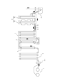
- FIG. 1 is a schematic diagram showing a schematic configuration of a continuous annealing facility according to an embodiment of the present disclosure.
- FIG. 2 is a schematic diagram showing another configuration of a continuous annealing facility according to an embodiment of the present disclosure.
- FIG. 3 is a schematic diagram showing the layout relationship between the cooling device and the induction heating device.
- FIG. 4 is a flow chart showing an example of a continuous annealing method.
- FIG. 1 shows a part of a hot-dip galvanizing process equipped with a continuous annealing facility according to the present embodiment.
- the steel material manufactured using the hot-dip galvanizing process is a thin steel sheet.
- the steel material manufactured is a cold-rolled steel sheet.
- the arrow in FIG. 1 indicates the line travel direction.
- the upstream side in this travel direction may be expressed as "front” and the downstream side as "rear”.
- the continuous annealing facility includes a payoff reel 1, a welding machine 2, an electrolytic cleaning device 3, an entry looper 4, a preheating zone 5, a heating zone 6, a soaking zone 7, and a cooling zone 8.
- the continuous annealing facility also includes an induction heating device 9 (hereinafter sometimes referred to as "IH"), a transformation rate meter 10, and a cooling device 13.
- the continuous annealing facility includes at least one induction heating device 9.
- the continuous annealing facility includes at least one transformation rate meter 10.
- the continuous annealing equipment is not limited to a configuration including the transformation ratio meter 10 as long as the phase fraction after annealing in the induction heating device 9 can be grasped.
- the continuous annealing equipment may be configured to predict the transformation ratio based on information from an installed thermometer instead of the transformation ratio meter 10.
- the continuous annealing equipment also includes at least one cooling device 13.
- the cooling zone 8 includes a first cooling zone 8A and a second cooling zone 8B.
- the continuous annealing equipment may further include a zinc plating tank (zinc pot 11) in which the thin steel sheet cooled to a predetermined temperature is immersed, an alloying zone, a holding zone, a final cooling zone, a temper rolling facility, an exit looper, a tension reel, and the like.
- the thin steel sheet wound into a coil in the previous process is unwound by the pay-off reel 1.
- the unwound thin steel sheet passes through the preheating zone 5 and then enters the continuous annealing furnace.
- the continuous annealing equipment is configured with a heating zone 6, a soaking zone 7, and a cooling zone 8, in that order, following the preheating zone 5.
- an induction heating device 9 is provided between the soaking zone 7 and the cooling zone 8.
- the continuous annealing equipment also includes a transformation rate meter 10 downstream of the induction heating device 9. In the example of FIG. 1, the transformation rate meter 10 is provided between the induction heating device 9 and the cooling zone 8, but the installation position is not limited as long as it is downstream of the outlet of the induction heating device 9.
- the transformation rate meter 10 can also be installed immediately after the induction heating device 9.
- the transformation rate meter 10 is an example of a measuring device that measures the austenite fraction ( ⁇ phase fraction) of the steel plate.
- a thermometer can be installed in the plate width direction in each annealing zone, and the results predicted from the steel plate dimensions and compositional performance, etc., can be used.
- the plate width direction is the width direction of the steel plate.
- the continuous annealing equipment is configured to include a mechanism for adjusting the output of the induction heating device 9 and the output of the cooling device 13 using the measurement results of the gamma phase fraction by the transformation rate meter 10.
- the continuous annealing equipment may be configured to change other annealing equipment conditions, such as the furnace temperature of the soaking zone 7, as necessary.
- the continuous annealing equipment according to this embodiment is not limited to the configuration of FIG. 1, and may be modified according to the desired quality of the steel sheet to be manufactured.
- a zinc pot 11 and an alloying zone may be provided following the continuous annealing furnace, or the zinc pot 11 may be omitted.
- the continuous annealing equipment may be partially divided.
- the soaking zone 7 may be divided, and each of the divided soaking zones 7 may independently control the atmosphere or temperature.
- Pre-tropical zone The thin steel plate discharged from the pay-off reel 1 at a temperature between room temperature and about 100° C. first enters the preheating zone 5 and is heated to about 200° C.
- the preheating zone 5 uses the high-temperature exhaust gas generated in the heating zone 6.
- the steel sheet enters the heating zone 6, where it is heated to a temperature of about 600 to 700°C.
- a direct-fired heating furnace is used in the heating zone 6 in order to raise the temperature to a certain level in a short time and to control the surface condition.
- a direct-fired heating furnace has high heating capacity and can reduce the volume of the furnace, and also allows for flexible control of the oxidation-reduction reaction on the steel sheet surface, taking into account the subsequent plating process.
- the soaking zone 7 mainly plays a role of promoting the recrystallization of the ⁇ phase. However, it does not matter if there are some parts that pass through the A1 transformation point at this time.
- a heating method for the soaking zone 7 it is desirable to adopt a radiant heating (radiant tube heating) method by gas combustion because of its high efficiency and heating uniformity.
- the soaking zone 7 may be composed of a large single furnace shell.
- the soaking zone 7 may have two or more compartments, each compartment may be separated by a heat insulating wall or the like, and the steel sheet may be held and heated in a target temperature range determined for each compartment.
- the soaking zone 7 holds or slowly heats the steel sheet so that the temperature is in a temperature range (about 600 to 730°C) lower than the A1 transformation point, thereby ensuring the residence time in the recrystallization temperature range and suppressing the remaining of the unrecrystallized ⁇ phase.
- the A1 transformation point is a temperature that causes austenite transformation
- the set furnace temperature is 730°C as an example.
- the austenite phase begins to occur at a temperature above the A1 transformation point.
- the recrystallization temperature range by predicting it in advance by measurement, calculation or simulation, and taking into account the error range during annealing.
- the continuous annealing equipment includes a soaking zone 7 using a radiant tube furnace, but may not include such a soaking zone 7 if it has the function of ensuring a heat retention time sufficient to advance ⁇ -phase recrystallization.
- the soaking zone 7 is not limited to having a radiant tube furnace.
- the continuous annealing equipment may not include a soaking zone 7, and the heating zone 6 may have the function of ensuring a heat retention time sufficient to advance ⁇ -phase recrystallization.
- the continuous annealing equipment may include a heat retention device instead of the soaking zone 7.
- the induction heating device 9 may be provided between the part that functions as the soaking zone 7 (the part or heat retention device that ensures the heat retention time of the heating zone 6 in the above example) and the cooling zone 8.
- the induction heating device 9 adjusts the output so that the temperature of the steel sheet is included in a temperature range (about 750 to 900 ° C.) that is equal to or higher than the A1 transformation point and lower than the A3 transformation point, and rapidly heats the steel sheet.
- the A3 transformation point is the upper limit temperature at which the ⁇ -phase fraction can be controlled.
- the purpose of this process is to uniformly heat the entire steel sheet to a temperature equal to or higher than the A1 transformation point in a short time so that the same ⁇ -phase fraction can be obtained at any location of the steel sheet.
- the adoption of the induction heating device 9 can also contribute to the miniaturization of the entire facility.
- the A1 transformation point and the A3 transformation point may vary slightly depending on the composition of the steel sheet. Therefore, it is preferable that the suitable temperature range is predicted in advance by measurement, calculation or simulation, and set after taking into consideration the error range during annealing.
- the temperature reached in the induction heating device 9 has a large effect on the mechanical properties of the final product. Therefore, the heating method of the induction heating device 9 needs to have a fast response to temperature control commands. Furthermore, when heating in this temperature range, the Curie point at which the magnetic properties of the steel sheet change is exceeded, so it is desirable for the induction heating device 9 to be of the transverse type.
- the induction heating device 9 may increase the temperature at 10°C/s or more and 200°C/s or less. If the heating rate is less than 10°C/s, the ⁇ -grains will become coarse, and if the heating rate is more than 200°C/s, local high-temperature areas will occur in the plate width direction and uniformity will not be maintained. It is more preferable that the induction heating device 9 increase the temperature at 20°C/s or more and 100°C/s or less. If the heating rate is 20°C/s or more, the line length can be shortened, and if the heating rate is 100°C/s or less, the risk of buckling deformation of the steel plate due to thermal stress can be further reduced.
- the induction heating device 9 When the induction heating device 9 is used to rapidly heat the steel to the target annealing temperature, it is possible that the transformation from the ⁇ phase to the ⁇ phase has not yet reached equilibrium immediately after heating. However, if the steel is held at near the target annealing temperature for too long, the transformation from the ⁇ phase to the ⁇ phase will proceed more than necessary, causing hardening, and the required elongation will not be obtained in the final product. Therefore, after the target annealing temperature is reached, it is most desirable to enter the steel into the cooling zone 8 as quickly as possible with a holding time of 0 seconds, and it is desirable for cooling to begin within 5 seconds. In order to avoid a non-equilibrium state, even if the steel is held, cooling will begin within 10 seconds at the latest. In other words, cooling of the steel sheet begins in the cooling zone 8 within 10 seconds after heating by the induction heating device 9 ends.
- the induction heating device 9 may be provided between the soaking zone 7 and the cooling zone 8.
- the induction heating device 9 is provided at the connection between the soaking zone 7 and the cooling zone 8, it is possible to add an induction heating device 9 to an existing furnace.
- the soaking zone 7 may be configured to be split into two zones, with the upstream zone performing holding in the recrystallization zone and the downstream zone performing holding in the high temperature zone to promote the reduction reaction on the steel sheet surface. Since there is a difference in the optimal temperature range for each zone, a first induction heating device 9 that rapidly heats from the low temperature zone to the temperature of the high temperature zone, and a second induction heating device 9 for the purpose of adjusting the temperature for material control just before entering the cooling zone 8 may be installed.
- the cooling device 13 is preferably a device that cools by spraying gas.
- the cooling device 13 cools the end of the steel plate with gas.
- the cooling device 13 is equipped with nozzles, and the nozzles may be attached to both the front and back sides of the steel plate so that gas is sprayed onto both sides (front and back) of the end of the steel plate.
- the range in which overheating occurs is a range of approximately 200 to 300 mm inward from each edge of the steel plate in the plate width direction. Therefore, as long as the nozzles can be positioned so as to specifically cool this range, the nozzle attachment is not limited to a specific form.
- the nozzle of the cooling device 13 may be a slit nozzle with a slit extending in the sheet width direction, or a nozzle with a small hole drilled in a nozzle header extending in the sheet width direction.
- the thickness of the slit can be set to any width, for example, between 1 and 5 mm.
- the small hole can be set to any diameter, for example, between 1 and 20 mm.
- the nozzles can be installed in multiple stages.
- the cooling gas is preferably a non-oxidizing gas (N 2 , H 2 , or a mixture thereof, etc.). In this case, the cooling gas is preferably a gas drawn from outside the furnace, not a high-temperature furnace gas.
- the cooling capacity of the cooling device 13 may be determined based on the passing speed of the steel plate, the dimensions of the steel plate, and the specifications of the induction heating device 9. It is desirable for the cooling device 13 to have a cooling performance capable of realizing a heat transfer coefficient of 50 to 500 W/( m2 ⁇ K). If the heat transfer coefficient exceeds 500 W/( m2 ⁇ K), the shape of the steel plate may be distorted, which may cause problems during transportation.
- the distance between the cooling device 13 and the induction heating device 9 is large, the steel sheet will be heated by the surrounding atmosphere before reaching the induction heating device 9 from the cooling device 13. As a result, the temperature distribution at the outlet side of the induction heating device 9 will not be uniform, which will cause the material to vary in the width direction.
- the heat transfer coefficient of heating by forced convection in the furnace atmosphere is estimated to be approximately 20 W/( m2 ⁇ K). Assuming a sheet passing speed of 100 mpm and a sheet thickness of 1 mm, the temperature rise at the outlet side of the soaking zone is about 5°C at a distance of 4 m and about 10°C at a distance of 8 m. From the above, from the viewpoint of uniforming the temperature variation in the width direction, the distance from the outlet side of the cooling device 13 to the inlet side of the induction heating device 9 is preferably within 8 m, more preferably within 4 m.
- a transformation rate meter 10 for measuring the phase fraction of the steel sheet is disposed downstream of the induction heating device 9, and the phase fractions (transformation rates) of the ⁇ -phase and ⁇ -phase of the steel sheet after the target annealing temperature is reached are measured.
- the transformation rate meter 10 is provided for the purpose of adjusting the operating conditions of the induction heating device 9, the cooling device 13, and the like, based on the measured ⁇ -phase fraction. By such adjustment, the mechanical properties of the steel sheet can be stably obtained.
- the installation position of the transformation rate meter 10 is not particularly limited as long as it is downstream of the induction heating device 9.
- the transformation rate meter 10 is installed between the exit of the induction heating device 9 and the entrance of the cooling zone 8.
- the method of measuring the transformation rate is not particularly limited.
- the austenite fraction may be measured using a magnetic detector, i.e., a magnetic transformation rate measuring device consisting of a driving coil that generates a magnetic field and a detection coil that measures the magnetic field that has passed through the steel strip, as a device for measuring the magnetic transformation rate of the steel strip.
- a magnetic transformation rate measuring device consisting of a driving coil that generates a magnetic field and a detection coil that measures the magnetic field that has passed through the steel strip
- the device described in JP 2019-7907 A can be used.
- the transformation rate meter 10 if the transformation rate meter 10 is installed near the induction heating device 9, the measurement accuracy may decrease due to the influence of the magnetic field.
- a device that applies the X-ray diffraction method can be used as a method that is not influenced by the magnetic field.
- ⁇ phase fraction can be quantified by the intensity of this diffraction peak.
- X-CAP manufactured by SMS.
- the transformation rate is preferably measured so as to obtain the phase fraction distribution in the plate width direction.
- at least three locations at the plate width center and both plate width ends may be measured.
- the plate width center is the central part of the steel plate in the plate width direction, and the center of the steel plate may be measured.
- the plate width ends are the parts close to each of both edges of the steel plate in the plate width direction.
- the measurement position at the plate width ends is not limited to a specific position, but it is necessary to measure at least one location within a range of 25 to 100 mm inward from the edge of the end of the steel plate.
- the method of determining the transformation rate is not limited to measurement using the transformation rate meter 10.
- a predicted value of the phase fraction may be used by calculation using a machine learning model or a physical model. In this case, it is desirable to install an appropriate thermometer inside the annealing furnace to improve the accuracy of the prediction model.
- the cooling zone 8 is a facility for cooling the steel sheet to a predetermined temperature, and gas jet cooling, roll cooling, water cooling (water quenching), etc. are used as the cooling means.
- the cooling zone 8 may be divided into a plurality of zones, such as a first cooling zone 8A and a second cooling zone 8B, and different cooling means may be combined or the cooling conditions of the same type of cooling means may be changed to control the thermal history of the steel sheet during cooling.
- a transformation rate meter 10 may be installed in the divided portion.
- Hot-dip galvanizing bath A hot-dip galvanizing bath is provided following the cooling zone 8, and hot-dip galvanizing can be applied to the surface of the steel sheet discharged from the cooling zone 8. Hot-dip galvanizing may be performed according to a conventional method, and a snout, a bath roll, and the like may be provided as necessary.
- the hot-dip galvanizing bath may be followed by an alloying treatment facility.
- the steel sheet is heated and subjected to an alloying treatment.
- the alloying treatment may be performed according to a conventional method.
- a holding zone, a final cooling zone, a temper rolling equipment, a straightener, an outlet looper, a tension reel, and the like may be further provided in order to improve the quality of the final product and to improve the manufacturing stability and efficiency.
- These facilities may be provided and used according to the quality required for the product, and are not particularly limited.
- straightening may be performed by passing the steel sheet through temper rolling equipment and a straightener. Temper rolling and straightening may be performed under conditions that allow the shape to be straightened without affecting the mechanical properties of the steel sheet.
- a "transformation ratio control model” is constructed by grasping in advance the optimum phase fraction range for each product, and the output of the induction heating device 9 or the output of the cooling device 13 is controlled so that the phase fraction measurement result by the transformation ratio meter 10 falls within the target range.
- other annealing equipment conditions such as the furnace temperature of the soaking zone 7, are also controlled as necessary. This makes it possible to manufacture products with very stable mechanical properties by further suppressing material variation in the sheet width direction, as compared to a method of simply homogenizing the steel sheet temperature during annealing in the sheet width direction.
- FIG. 4 is a flowchart showing an example of a continuous annealing method performed in the continuous annealing equipment in this embodiment.
- This continuous annealing method may be performed by a control device associated with the continuous annealing equipment, such as a process computer that accumulates and manages operating condition results.
- the phase fraction of the steel sheet that has passed through the induction heating device 9 is acquired as "actual transformation rate information.”
- the phase fraction may be a measured value or a predicted value.
- information on the dimensions of the steel sheet, such as the chemical composition, thickness, and width, obtained when the material is cast, is acquired as “material information.”
- the manufacturing conditions of the passing process may be acquired as material information.
- Information on the conveying speed of the steel sheet during annealing, the set furnace temperature, the atmosphere gas in the furnace, and the cooling conditions are acquired as "operating conditions of the continuous annealing equipment.” Based on this information, the mechanical properties (mechanical characteristics) of the final product are predicted using a "material prediction model.”
- the material prediction model may be a physical model obtained by offline experiments or numerical analysis.
- the material prediction model may be a machine learning model generated by machine learning using accumulated manufacturing results as learning data.
- the target range of the mechanical properties is given by the host computer.
- the host computer is a computer that gives manufacturing information, etc. to the process computer that manages the operation of the continuous annealing equipment. If the results are within the target range ("Mechanical properties within target range" in Figure 4 is Yes), the continuous annealing equipment continues operation under the current conditions (i.e., under the same conditions). If the results are outside the target range ("Mechanical properties within target range" in Figure 4 is No), the continuous annealing equipment changes the operating conditions.
- the amount of phase fraction adjustment required to bring the material within the target range is calculated from the material prediction model described above, and a "transformation rate control model” is used to calculate the amount of steel sheet temperature control to achieve the amount of transformation rate adjustment.
- the "transformation rate control model” may be a physical model obtained by offline laboratory experiments or numerical analysis, or a machine learning model obtained from accumulated manufacturing experience.
- the gamma phase is suitable as the metal phase to be adjusted.
- the continuous annealing equipment determines that the required steel sheet temperature control amount is within the controllable range of the cooling device 13 on the inlet side of the induction heating device 9 ("Within cooling device control range” in Figure 4 is Yes), it changes the cooling amount by only changing the output of the cooling device 13 ("Change cooling amount of cooling device” in Figure 4). If the continuous annealing equipment determines that the required steel sheet temperature control amount is not within the controllable range of the cooling device 13 ("Within cooling device control range" in Figure 4 is No), it also changes the conditions of the induction heating device 9.
- the continuous annealing equipment determines that the required steel sheet temperature control amount is within the range that can be controlled by the induction heating device 9 ("Within IH output control range" in FIG. 4 is Yes), it changes the output of the induction heating device 9.
- the continuous annealing equipment determines that the required steel sheet temperature control amount is not within the range that can be controlled by the induction heating device 9 ("Within IH output control range” in FIG. 4 is No)
- it also changes the conditions of the cooling device 13 and equipment other than the induction heating device 9 (“Change other annealing equipment conditions" in FIG. 4).
- other annealing equipment refers to the soaking zone 7 or cooling zone 8, etc.
- annealing equipment has a lower responsiveness to changes in operating conditions compared to the induction heating device 9, but by controlling it in combination with the induction heating device 9 via the above control flow from moment to moment even while the conditions are changing, it is possible to minimize the amount by which the mechanical properties of the product deviate from the target.
- the cooling device 13 creates a temperature difference between the sheet width end and the sheet width center in advance to eliminate this difference.
- the cooling amount required to create the temperature difference is calculated using the following method.
- ⁇ is approximately 2.
- the value of ⁇ is empirically obtained, for example, from laboratory experiments or accumulated manufacturing conditions and performance. If the widthwise center portion of the steel sheet is heated by 100° C. ( ⁇ T C is 100° C.) by the induction heating device 9, the widthwise end portion of the steel sheet is heated by an additional 100° C. ( ⁇ T E is approximately 200° C.) compared to the widthwise center portion of the steel sheet. Therefore, the widthwise end portion of the steel sheet may be cooled by the cooling device 13 by an amount sufficient to eliminate the temperature difference (approximately 100° C. in this example) just before the steel sheet is transported to the induction heating device 9.
- the temperature T EA of the widthwise end portion of the steel sheet after passing through the cooling device 13 has the following relationship of formula (2).
- T S is the temperature of the cooling gas
- T EA is the temperature of the width end of the plate after passing through the cooling device 13
- T EB is the temperature of the width end of the plate before passing through the cooling device 13
- h is the heat transfer coefficient of gas cooling (W/(m 2 ⁇ K))
- S is the surface area (m 2 ) of the steel plate in the cooling device 13
- c is the specific heat of the steel plate (J/(kg ⁇ K))
- ⁇ is the density of the steel plate (kg/m 3 )
- V is the volume (m 3 ) of the steel plate in the cooling device 13
- t is the time (s) that the steel plate passes through the cooling device 13.
- the cooling conditions are calculated so that, for example, T EB , which is the temperature at the sheet width end portion before cooling, is 800°C, and T EA is 700°C, using formula (2) and information on the conveying speed, specific heat, density, etc. of the steel sheet.
- the amount of cooling can be changed by controlling the temperature or flow rate of the gas used for cooling.
- the method for changing the amount of cooling there are no limitations on the method for changing the amount of cooling, but it is particularly desirable to control the flow rate by changing the gas ejection pressure.
- the relationship between the heat transfer coefficient of the cooling device and a controllable parameter e.g., gas flow rate or pressure
- the control parameters of the cooling device 13 may be changed so that the target amount of cooling is obtained at the plate width end. If the magnitude of variation in the gamma fraction is within a range of 10%, for example, at all positions in the width direction of the steel plate, the uniformity of the material is ensured.
- JP Patent Publication 7-418678 discloses a structure in which cooling pipes through which air or water passes as a cooling medium are arranged on the inner surface of the furnace wall in a non-oxidizing furnace type heating furnace using a flame burner as a method of suppressing overheating of the steel plate edge.
- this type of indirect cooling even if the cooling conditions such as the flow rate of the refrigerant are changed, it takes time for the temperature of the fluid in the furnace to change. Therefore, when the heat capacity of the plate changes due to a change in the plate passing speed or a change in plate thickness, it takes a certain amount of time for the plate temperature to reach the target temperature.
- the continuous annealing equipment anneals steel materials including DP steel to stably obtain the target mechanical properties.
- Specific examples of the steel sheets to be treated include, by weight, C 0.05% to 0.25%, Si 0.01% to 2.00%, Mn 0.50% to 4.00%, P 0.100% or less, S 0.0500% or less, and Sol.
- steel sheets examples include those containing 0.005% or more and 0.100% or less of Al, 0.100% or less of N, and optionally containing Cr, Cu, Ni, Sb, Sn (all 1.00% or less), Mo, V, Ti, Nb (all 0.50% or less), Ta (0.10% or less), Mg, Zr (all 0.050% or less), B, Ca, and REM (all 0.0050% or less), with the balance being Fe and unavoidable impurities.
- the steel sheet to be targeted is not limited as long as it is necessary to control the two-phase structure of ⁇ phase and ⁇ phase.
- Table 1 shows the conditions and results of producing thin steel sheets using a conventional continuous annealing facility and a continuous annealing facility according to the present embodiment (see Figs. 1 and 2).
- Comparative Example 1 Comparative Example 2, Comparative Example 1, and Example 2, three types of strength levels, 780 MPa, 980 MPa, and 1180 MPa, were produced, and three types of plate thicknesses, 1.0, 1.5, and 2.0 mm, were produced in ten pieces at each strength level.
- the ten slabs of each plate thickness in each grade were all cast in different lots using a continuous casting machine. Therefore, although within the manufacturing control range, the chemical composition of each slab varies and the transformation behavior is not uniform.
- Each slab was hot-rolled and pickled by a general method, and annealed and cold-rolled as necessary, and then heat-treated in a conventional continuous annealing facility and the continuous annealing facility disclosed herein, followed by post-treatment such as cooling and plating.
- Three arbitrary locations were selected in the steel sheet conveying direction (longitudinal direction) of the final product coil, and tensile test pieces were taken from three locations, the center of the sheet width and both ends of the sheet width (positions 50 mm toward the center from both edges), and mechanical properties were measured. In other words, a total of nine test pieces were taken for each final product coil, and mechanical properties were measured.
- the tensile test pieces were JIS No. 5.
- the tensile test was performed in accordance with JIS Z2241.
- the material was judged to be stable when the variation in TS (tensile strength) measured by the tensile test was within the range of 60 MPa, and the material was judged to be variable when it was greater than the range of -30 MPa to +30 MPa. Additionally, for the 780 MPa, 980 MPa, and 1180 MPa grades, the required strength ranges are 780 MPa or more, 980 MPa or more, and 1180 MPa or more, respectively.
- Comparative example 1 was manufactured from the above-mentioned material using a conventional annealing furnace consisting of a preheating zone 5, a heating zone 6, and a soaking zone 7, without an induction heating device 9 and a transformation rate meter 10.
- the line speed in the manufacturing process was in the range of 60 to 120 mpm, and the change in the steel sheet temperature was controlled according to the sheet thickness.
- the steel sheet temperature at the exit of the heating zone 6 (direct flame heating) was in the range of 600 to 700°C to control the oxidation-reduction reaction on the surface. Further heating was then performed in the soaking zone 7 using a radiant tube method.
- the steel sheet temperature at the exit of the soaking zone 7 (entrance to the cooling zone 8) was in the range of 770 to 870°C.
- the furnace temperature of the soaking zone 7 was controlled so that the steel sheet temperature at the exit was the target value.
- multiple material test pieces were taken from the final product after cooling, hot-dip galvanizing, alloying, etc., and the variation in mechanical properties was investigated.
- the tensile strength varied greatly among the grades, and some were below the lower limit of each grade. This is believed to be due to the phase fraction during annealing not reaching the target value due to fluctuations in the chemical composition of the material, and when the annealing conditions changed at the joints of coils with different thicknesses and grades, there were areas where the heating conditions could not keep up.
- Comparative Example 2 the continuous annealing equipment shown in FIG. 1 was used, but the cooling device 13 was not used to manufacture the product. Therefore, the cooling device is indicated as "none" in Table 1.
- the transformation rate meter 10 is placed in the middle of the cooling zone 8, that is, between the first cooling zone 8A and the second cooling zone 8B.
- the sheet passing speed and the outlet temperature of the heating zone 6 were controlled in the same range as in Comparative Example 1.
- the phase fraction in the center of the sheet width during annealing was measured by the transformation rate meter 10 at the outlet of the cooling zone 8, and the output of the induction heating device 9 and the furnace temperature of the soaking zone 7 were controlled.
- Example 1 shows the results of manufacturing a product using the continuous annealing equipment shown in Figure 1 and the cooling device 13.
- the transformation rate meter 10 is placed in the middle of the cooling zone 8, that is, between the first cooling zone 8A and the second cooling zone 8B.
- the phase fractions of the center and end portions of the strip width were measured by the transformation rate meter 10, and the output of the induction heating device 9, the furnace temperature of the soaking zone 7, and the cooling amount of the cooling device 13 on the inlet side of the induction heating device 9 were appropriately controlled in accordance with the control flow in Figure 4.
- an appropriate cooling amount of the cooling device 13 could be set, and the material variation was greatly improved in both the center and end portions of the strip width.
- the material variation of the end portions of the strip width became the same as that of the center portion of the strip width.
- Example 2 shows the results of manufacturing a product using the continuous annealing equipment shown in Figure 2 and the cooling device 13.
- the transformation rate meter 10 is placed immediately after the induction heating device 9.
- the phase fractions of the center and end portions of the plate width were measured by the transformation rate meter 10, and the output of the induction heating device 9, the furnace temperature of the soaking zone 7, and the cooling amount of the cooling device 13 on the inlet side of the induction heating device 9 were controlled.
- an appropriate cooling amount of the cooling device 13 could be set, and the material variation was greatly improved in both the center and end portions of the plate width.
- the material variation of the end portions of the plate width became the same as that of the center portion of the plate width.
- the transformation rate meter 10 immediately after the induction heating device 9, it became possible to measure the ⁇ fraction immediately before the end of annealing, and the operating conditions could be quickly corrected. Therefore, the material variation was reduced compared to Example 1.
- the continuous annealing equipment, continuous annealing method, manufacturing method for cold-rolled steel sheet, and manufacturing method for plated steel sheet according to this embodiment can suppress the occurrence of material variations in the sheet width direction by using the above-mentioned configuration. Furthermore, the continuous annealing equipment according to this embodiment uses an induction heating device 9 that has high heating capacity and fast response to temperature control, which makes it possible to reduce the line length compared to conventional methods, and is therefore expected to reduce the introduction costs of manufacturing equipment.
- the zinc pot 11 has been described as a zinc plating bath in which the thin steel sheet is immersed, but another plating process may be performed.
- the plating process may be, for example, an electrolytic zinc plating process, a hot-dip galvanizing process, or an alloyed hot-dip galvanizing process.
- the processor of the process computer may read and execute a program stored in a storage unit (e.g., a memory) of the process computer to execute processes such as controlling the output of the induction heating device 9, the furnace temperature of the soaking zone 7, and the cooling amount of the cooling device 13.
- a storage unit e.g., a memory
- the processor of the process computer may function as the above-mentioned control device by the program.
Landscapes
- Chemical & Material Sciences (AREA)
- Engineering & Computer Science (AREA)
- Materials Engineering (AREA)
- Metallurgy (AREA)
- Organic Chemistry (AREA)
- Mechanical Engineering (AREA)
- Physics & Mathematics (AREA)
- Thermal Sciences (AREA)
- Crystallography & Structural Chemistry (AREA)
- Chemical Kinetics & Catalysis (AREA)
- Oil, Petroleum & Natural Gas (AREA)
- Electromagnetism (AREA)
- Electrochemistry (AREA)
- Power Engineering (AREA)
- Heat Treatment Of Strip Materials And Filament Materials (AREA)
Abstract
Description
加熱帯、均熱帯及び冷却帯をこの順に備えて構成される鋼板の連続焼鈍設備であって、
前記均熱帯と前記冷却帯との間に設けられた誘導加熱装置と、
前記誘導加熱装置の入口で前記鋼板の端部をガスによって冷却する冷却装置と、
前記誘導加熱装置より下流における前記鋼板の相分率に基づいて、前記誘導加熱装置及び前記冷却装置の操業条件を制御する制御装置と、を備える。
前記相分率は、前記誘導加熱装置より下流に設置された変態率計を用いて測定される。
加熱帯、均熱帯及び冷却帯をこの順に備えて構成される鋼板の連続焼鈍設備で実行される連続焼鈍方法であって、
前記均熱帯と前記冷却帯との間に設けられた誘導加熱装置によって急速加熱を実施するステップと、
冷却装置によって前記誘導加熱装置の入口で前記鋼板の端部を冷却するステップと、
前記誘導加熱装置より下流における前記鋼板の相分率に基づいて、前記誘導加熱装置及び前記冷却装置の操業条件を制御するステップと、を含む。
前記誘導加熱装置は10℃/s以上、200℃/s以下で前記鋼板を加熱する。
前記相分率は、前記誘導加熱装置より下流に設置された変態率計を用いて測定される。
(3)から(5)のいずれかの連続焼鈍方法によって冷延鋼板である前記鋼板を焼鈍する。
(6)の冷延鋼板の製造方法によって焼鈍された前記鋼板の表面にめっき処理を施すステップを含む。
前記めっき処理は、電気亜鉛めっき処理、溶融亜鉛めっき処理又は合金化溶融亜鉛めっき処理である。
図1は、本実施形態に係る連続焼鈍設備を備えた溶融亜鉛めっきプロセスの一部を示す。本実施形態において、溶融亜鉛めっきプロセスを用いて製造される鋼材は薄鋼板である。また、製造される鋼材は冷延鋼板である。図1の矢印はライン進行方向を示す。以下において、この進行方向における上流側を「前」と、下流側を「後」と表現することがある。連続焼鈍設備は、ペイオフリール1、溶接機2、電解清浄装置3、入側ルーパー4、予熱帯5、加熱帯6、均熱帯7及び冷却帯8を備える。また、連続焼鈍設備は、誘導加熱装置9(Induction Heating device、以下「IH」と称されることがある)、変態率計10及び冷却装置13を備える。連続焼鈍設備は少なくとも1つの誘導加熱装置9を備える。本実施形態において、連続焼鈍設備は少なくとも1つの変態率計10を備える。しかし、連続焼鈍設備は、誘導加熱装置9で焼鈍した後の相分率を把握できれば、変態率計10を備える構成に限定されない。例えば、連続焼鈍設備は、変態率計10でなく、設置された温度計の情報に基づいて変態率を予測する構成であってよい。また、連続焼鈍設備は少なくとも1つの冷却装置13を備える。本実施形態において、冷却帯8は第1の冷却帯8Aと、第2の冷却帯8Bと、を含む。また、連続焼鈍設備は、所定の温度まで冷却された薄鋼板を浸漬する亜鉛めっき槽(亜鉛ポット11)、合金化帯、保熱帯、最終冷却帯、調質圧延設備、出側ルーパー、テンションリールなどをさらに備えてよい。
常温~100℃程度の温度でペイオフリール1から払い出された薄鋼板は、まず、予熱帯5に進入し200℃程度まで加熱される。本実施形態において、予熱帯5は加熱帯6で生じる高温の排気を利用する方式が採用されている。
続いて、鋼板は加熱帯6に進入し、鋼板温度が600~700℃程度まで加熱される。本実施形態において、加熱帯6は、短時間である程度の温度まで昇温し、かつ、表面状態を制御するため、直火加熱炉方式が採用されている。直火式加熱炉は、加熱能力が高く炉の容積を小さくできることに加え、鋼板表面の酸化還元反応について、後のめっきプロセスを考慮した柔軟な制御が可能である。
均熱帯7は、α相の再結晶を進行させることを主な役割とする。ただし、この際にA1変態点を通過する箇所があっても構わない。均熱帯7の加熱方式として、効率と加熱均一性の高さからガス燃焼による輻射加熱(ラジアントチューブ加熱)方式を採用することが望ましい。均熱帯7は大きな単一の炉殻で構成されてよい。また、均熱帯7は2つ以上の区画を有し、各区画を遮熱壁などで分離して、区画毎に決められた目標温度域で保持及び加熱を行う構成としてよい。本実施形態において、均熱帯7は、鋼板の温度がA1変態点より低い温度域(600~730℃程度)であるように保持又は緩速加熱を行って、再結晶温度域での滞在時間を確保し、未再結晶α相の残留を抑制する。ここで、A1変態点は、オーステナイト変態を生じさせる温度であって、一例として設定炉温が730℃である。換言すると、A1変態点以上の温度でオーステナイト相が発生し始める。
次に、誘導加熱装置9は、鋼板の温度がA1変態点以上かつA3変態点より低い温度域(750~900℃程度)に含まれるように、出力を調整して、鋼板を急速加熱する。ここで、A3変態点は、γ相分率を制御できる上限の温度である。鋼板のいずれの場所でも同一のγ相分率が得られるように、このプロセスは、短時間で、鋼板全体を均一にA1変態点以上の温度まで昇温することが目的である。誘導加熱装置9を採用することにより、設備全体の小型化にも寄与することができる。ここで、A1変態点及びA3変態点は、鋼板の成分によって若干変動する場合がある。そのため、好適な温度域は、あらかじめ測定、計算又はシミュレーションにより予測し、焼鈍中の誤差範囲を考慮した上で設定されることが好ましい。
誘導加熱装置9で鋼板を加熱する場合に、鋼板に発生した渦電流は板幅方向の両端部(エッジ)に集中する性質がある。そのため、板幅方向の両端部は、中央部分よりも高温になることが知られている。加熱後の鋼板の温度を板幅方向で均一化するため、図3のように鋼板の両端部を予め冷却する冷却装置13が誘導加熱装置9の入側に設置される。
誘導加熱装置9より下流には鋼板の相分率を測定する変態率計10が配置されており、目標焼鈍温度到達後の鋼板のα相及びγ相の相分率(変態率)が測定される。この変態率計10は、測定したγ相分率に基づき、誘導加熱装置9、冷却装置13などの操業条件を調整する目的で設けられている。このような調整によって、鋼板の機械的性質を安定して得ることができる。ここで、変態率計10の設置位置としては、誘導加熱装置9より下流であれば特に限定されない。ただし、測定値をフィードバックして、誘導加熱装置9などの制御に用いる観点から、なるべく誘導加熱装置9に近いことが望ましい。その観点では、冷却帯の出口よりは上流に設置することが好ましい。ただし、変態率計10の耐熱性を考慮して設置される必要がある。より迅速にフィードバックするために、変態率計10は、誘導加熱装置9の出口から冷却帯8の入口の間に設けられることがより好ましい。
冷却帯8は、鋼板を所定の温度まで冷却する設備であり、冷却手段としてガスジェット冷却、ロール冷却、水冷却(ウォータークエンチ)などが用いられる。本実施形態のように、冷却帯8を第1の冷却帯8Aと第2の冷却帯8Bなど複数に区分して、異なる冷却手段を組み合わせたり、同種の冷却手段の冷却条件を変更したりして、鋼板の冷却時の熱履歴が制御されてよい。また、冷却帯を分割した際に、分割部分に変態率計10が設置されてよい。
冷却帯8に溶融亜鉛めっき浴を後続させ、冷却帯8から排出される鋼板の表面に溶融亜鉛めっきを施すことができる。溶融亜鉛めっきは常法に従って行えばよく、必要に応じて、スナウト、浴中ロールなどを設けてよい。
溶融亜鉛めっき浴に続いて合金化処理設備が設けられてよい。合金化処理設備では鋼板を加熱し合金化処理を施す。合金化処理は常法に従って行えばよい。
合金化設備に続いて、最終製品の品質向上と製造安定性及び効率化のため、保熱帯、最終冷却帯、調質圧延設備、矯正機、出側ルーパー、テンションリールなどがさらに備えられてよい。これらの設備は製品に要求される品質に応じて設け、使用されればよく、特に限定されるものではない。また、形状の乱れが生じた場合に、調質圧延設備及び矯正機を通板させることによって矯正が行われてよい。調質圧延及び矯正は、鋼板の機械的性質に影響を与えずに形状を矯正可能な条件で行えばよい。
本実施形態では、製品毎に最適な相分率の範囲を事前に把握して「変態率制御モデル」を構築し、変態率計10での相分率の測定結果が、目標の範囲に収まるように誘導加熱装置9の出力又は冷却装置13の出力を制御する。また、本実施形態では、必要に応じて均熱帯7の炉温など、その他の焼鈍設備条件についても制御する。このことによって、単に板幅方向で焼鈍時の鋼板温度を均一化する手法と比べて、さらに板幅方向における材質ばらつきを抑えて、機械特性が非常に安定した製品を製造することが可能になる。


本実施形態に係る連続焼鈍設備は、DP鋼を含む鋼材を焼鈍し、目標とする機械的性質を安定的に得るものである。対象とする鋼板の具体例として、重量%で、Cが0.05%以上かつ0.25%以下、Siが0.01%以上かつ2.00%以下、Mnが0.50%以上かつ4.00%以下、Pが0.100%以下、Sが0.0500%以下、Sol.Alが0.005%以上かつ0.100%以下、Nが0.100%以下を含有し、必要に応じてCr、Cu、Ni、Sb、Sn(いずれも1.00%以下)、Mo、V、Ti、Nb(いずれも0.50%以下)、Ta(0.10%以下)、Mg、Zr(いずれも0.050%以下)、B、Ca、REM(いずれも0.0050%以下)を含有し、残部がFe及び不可避不純物からなるものが挙げられる。ただし、対象とする鋼板は、α相、γ相の二相組織を制御する必要性があるものであれば限定されない。
表1は、従来の連続焼鈍設備、本実施形態に係る連続焼鈍設備(図1及び図2参照)を用いて、薄鋼板を製造した条件と結果を示す。比較例1、比較例2、実施例1及び実施例2について、強度レベルが780MPa、980MPa、1180MPa級の3種類を製造し、板厚は各々の強度レベルで1.0、1.5、2.0mmの3種類を10本ずつ製造した。各グレードにおける各板厚の10本のスラブは、連続鋳造機において全て異なるロットで鋳造されたものを使用した。そのため、製造管理範囲内ではあるが各スラブの化学成分はばらついており変態挙動も均一にはなっていない。

2 溶接機
3 電解清浄装置
4 入側ルーパー
5 予熱帯
6 加熱帯
7 均熱帯
8 冷却帯
8A 第1の冷却帯
8B 第2の冷却帯
9 誘導加熱装置
10 変態率計
11 亜鉛ポット
13 冷却装置
Claims (8)
- 加熱帯、均熱帯及び冷却帯をこの順に備えて構成される鋼板の連続焼鈍設備であって、
前記均熱帯と前記冷却帯との間に設けられた誘導加熱装置と、
前記誘導加熱装置の入口で前記鋼板の端部をガスによって冷却する冷却装置と、
前記誘導加熱装置より下流における前記鋼板の相分率に基づいて、前記誘導加熱装置及び前記冷却装置の操業条件を制御する制御装置と、を備える、連続焼鈍設備。 - 前記相分率は、前記誘導加熱装置より下流に設置された変態率計を用いて測定される、請求項1に記載の連続焼鈍設備。
- 加熱帯、均熱帯及び冷却帯をこの順に備えて構成される鋼板の連続焼鈍設備で実行される連続焼鈍方法であって、
前記均熱帯と前記冷却帯との間に設けられた誘導加熱装置によって急速加熱を実施するステップと、
冷却装置によって前記誘導加熱装置の入口で前記鋼板の端部を冷却するステップと、
前記誘導加熱装置より下流における前記鋼板の相分率に基づいて、前記誘導加熱装置及び前記冷却装置の操業条件を制御するステップと、を含む、連続焼鈍方法。 - 前記誘導加熱装置は10℃/s以上、200℃/s以下で前記鋼板を加熱する、請求項3に記載の連続焼鈍方法。
- 前記相分率は、前記誘導加熱装置より下流に設置された変態率計を用いて測定される、請求項3又は4に記載の鋼板の連続焼鈍方法。
- 請求項3から5のいずれか一項に記載の連続焼鈍方法によって冷延鋼板である前記鋼板を焼鈍する、冷延鋼板の製造方法。
- 請求項6に記載の冷延鋼板の製造方法によって焼鈍された前記鋼板の表面にめっき処理を施すステップを含む、めっき鋼板の製造方法。
- 前記めっき処理は、電気亜鉛めっき処理、溶融亜鉛めっき処理又は合金化溶融亜鉛めっき処理である、請求項7に記載のめっき鋼板の製造方法。
Priority Applications (5)
| Application Number | Priority Date | Filing Date | Title |
|---|---|---|---|
| CN202380091340.7A CN120530210A (zh) | 2023-02-27 | 2023-11-15 | 连续退火设备、连续退火方法、冷轧钢板的制造方法以及镀覆钢板的制造方法 |
| KR1020257021464A KR20250116088A (ko) | 2023-02-27 | 2023-11-15 | 연속 어닐링 설비, 연속 어닐링 방법, 냉연 강판의 제조 방법 및 도금 강판의 제조 방법 |
| JP2024513286A JP7747181B2 (ja) | 2023-02-27 | 2023-11-15 | 連続焼鈍設備、連続焼鈍方法、冷延鋼板の製造方法及びめっき鋼板の製造方法 |
| EP23925379.2A EP4624598A4 (en) | 2023-02-27 | 2023-11-15 | CONTINUOUS ANNEALING EQUIPMENT, CONTINUOUS ANNEALING PROCESS, PROCESS FOR MANUFACTURING COLD-ROLL-ROLL STEEL SHEET AND PROCESS FOR MANUFACTURING CLAMED STEEL SHEET |
| MX2025010088A MX2025010088A (es) | 2023-02-27 | 2025-08-26 | Linea de recocido continuo, metodo de recocido continuo, metodo de produccion de lamina de acero laminada en frio, y metodo de produccion de lamina de acero recubierta o enchapada |
Applications Claiming Priority (2)
| Application Number | Priority Date | Filing Date | Title |
|---|---|---|---|
| JP2023-028934 | 2023-02-27 | ||
| JP2023028934 | 2023-02-27 |
Publications (1)
| Publication Number | Publication Date |
|---|---|
| WO2024180826A1 true WO2024180826A1 (ja) | 2024-09-06 |
Family
ID=92590249
Family Applications (1)
| Application Number | Title | Priority Date | Filing Date |
|---|---|---|---|
| PCT/JP2023/041124 Ceased WO2024180826A1 (ja) | 2023-02-27 | 2023-11-15 | 連続焼鈍設備、連続焼鈍方法、冷延鋼板の製造方法及びめっき鋼板の製造方法 |
Country Status (6)
| Country | Link |
|---|---|
| EP (1) | EP4624598A4 (ja) |
| JP (1) | JP7747181B2 (ja) |
| KR (1) | KR20250116088A (ja) |
| CN (1) | CN120530210A (ja) |
| MX (1) | MX2025010088A (ja) |
| WO (1) | WO2024180826A1 (ja) |
Citations (8)
| Publication number | Priority date | Publication date | Assignee | Title |
|---|---|---|---|---|
| JPS6269160A (ja) * | 1985-09-24 | 1987-03-30 | Kawasaki Steel Corp | 鋼材の相分率測定方法 |
| JPS62281290A (ja) * | 1986-05-29 | 1987-12-07 | 株式会社明電舎 | 平板の均熱誘導加熱方法とその装置 |
| JPH0741868A (ja) | 1993-07-26 | 1995-02-10 | Nippon Steel Corp | 連続焼鈍炉 |
| WO1997000975A1 (fr) * | 1995-06-23 | 1997-01-09 | Nippon Steel Corporation | Procede de recuit en continu de toles d'acier laminees a froid et equipement correspondant |
| JP2001006860A (ja) * | 1999-06-21 | 2001-01-12 | Sumitomo Heavy Ind Ltd | 誘導加熱装置 |
| JP2019007907A (ja) | 2017-06-28 | 2019-01-17 | Jfeスチール株式会社 | 焼鈍炉中の鋼板の磁気変態率測定方法および磁気変態率測定装置、連続焼鈍プロセス、連続溶融亜鉛めっきプロセス |
| JP2019505686A (ja) * | 2015-12-04 | 2019-02-28 | アーコニック インコーポレイテッドArconic Inc. | 横方向フラックス誘導熱処理中に導電性薄板を冷却する方法 |
| WO2022209364A1 (ja) * | 2021-03-30 | 2022-10-06 | Jfeスチール株式会社 | 連続焼鈍設備、連続焼鈍方法、冷延鋼板の製造方法及びめっき鋼板の製造方法 |
Family Cites Families (12)
| Publication number | Priority date | Publication date | Assignee | Title |
|---|---|---|---|---|
| JPS5938287B2 (ja) * | 1979-10-29 | 1984-09-14 | 川崎製鉄株式会社 | 複合組織鋼板の連続焼鈍方法および装置 |
| JPS6092428A (ja) * | 1983-10-25 | 1985-05-24 | Chugai Ro Kogyo Kaisha Ltd | 金属ストリツプの誘導加熱装置 |
| JPH01232685A (ja) | 1988-03-11 | 1989-09-18 | Mitsubishi Heavy Ind Ltd | 鋼板誘導加熱装置 |
| JPH093552A (ja) * | 1995-06-23 | 1997-01-07 | Nippon Steel Corp | 溶融亜鉛めっき鋼板を効率的に製造する連続溶融亜鉛めっき設備 |
| JPH10152728A (ja) * | 1996-11-25 | 1998-06-09 | Nippon Steel Corp | 加工性および表面性状に優れる冷延鋼板の製造方法 |
| JP3590578B2 (ja) | 1999-12-16 | 2004-11-17 | 管水工業株式会社 | 管ライニング工法及び管ライニング材の反転用ガイドチューブ |
| DE60133936D1 (de) * | 2000-12-18 | 2008-06-19 | Jfe Steel Corp | Verfahren zur herstellung einer stahlplatte und einrichtungen hierfür |
| JP4228654B2 (ja) * | 2002-10-24 | 2009-02-25 | Jfeスチール株式会社 | 鋼板の熱処理方法および装置 |
| AT514380B1 (de) * | 2013-05-03 | 2015-04-15 | Siemens Vai Metals Tech Gmbh | Bestimmung des ferritischen Phasenanteils nach dem Erwärmen oder Abkühlen eines Stahlbands |
| JP6812999B2 (ja) | 2018-03-30 | 2021-01-13 | Jfeスチール株式会社 | 金属帯の誘導加熱装置、金属帯の製造方法、及び合金化溶融亜鉛めっき鋼板の製造方法 |
| CN112313353A (zh) * | 2018-06-21 | 2021-02-02 | 首要金属科技美国有限责任公司 | 用于使用电磁传感器在热加工设备中控制钢带微结构的方法和系统 |
| MX2023002633A (es) * | 2020-09-03 | 2023-03-22 | Jfe Steel Corp | Metodo para predecir el contenido de hidrogeno en el acero de la tira de acero, metodo para controlar el contenido de hidrogeno en el acero, metodo de fabricacion, metodo para formar un modelo de prediccion del contenido de hidrogeno en el acero, y dispositivo que predice el contenido de hidrogeno en el acero. |
-
2023
- 2023-11-15 KR KR1020257021464A patent/KR20250116088A/ko active Pending
- 2023-11-15 WO PCT/JP2023/041124 patent/WO2024180826A1/ja not_active Ceased
- 2023-11-15 EP EP23925379.2A patent/EP4624598A4/en active Pending
- 2023-11-15 JP JP2024513286A patent/JP7747181B2/ja active Active
- 2023-11-15 CN CN202380091340.7A patent/CN120530210A/zh active Pending
-
2025
- 2025-08-26 MX MX2025010088A patent/MX2025010088A/es unknown
Patent Citations (8)
| Publication number | Priority date | Publication date | Assignee | Title |
|---|---|---|---|---|
| JPS6269160A (ja) * | 1985-09-24 | 1987-03-30 | Kawasaki Steel Corp | 鋼材の相分率測定方法 |
| JPS62281290A (ja) * | 1986-05-29 | 1987-12-07 | 株式会社明電舎 | 平板の均熱誘導加熱方法とその装置 |
| JPH0741868A (ja) | 1993-07-26 | 1995-02-10 | Nippon Steel Corp | 連続焼鈍炉 |
| WO1997000975A1 (fr) * | 1995-06-23 | 1997-01-09 | Nippon Steel Corporation | Procede de recuit en continu de toles d'acier laminees a froid et equipement correspondant |
| JP2001006860A (ja) * | 1999-06-21 | 2001-01-12 | Sumitomo Heavy Ind Ltd | 誘導加熱装置 |
| JP2019505686A (ja) * | 2015-12-04 | 2019-02-28 | アーコニック インコーポレイテッドArconic Inc. | 横方向フラックス誘導熱処理中に導電性薄板を冷却する方法 |
| JP2019007907A (ja) | 2017-06-28 | 2019-01-17 | Jfeスチール株式会社 | 焼鈍炉中の鋼板の磁気変態率測定方法および磁気変態率測定装置、連続焼鈍プロセス、連続溶融亜鉛めっきプロセス |
| WO2022209364A1 (ja) * | 2021-03-30 | 2022-10-06 | Jfeスチール株式会社 | 連続焼鈍設備、連続焼鈍方法、冷延鋼板の製造方法及びめっき鋼板の製造方法 |
Non-Patent Citations (1)
| Title |
|---|
| See also references of EP4624598A1 |
Also Published As
| Publication number | Publication date |
|---|---|
| EP4624598A1 (en) | 2025-10-01 |
| KR20250116088A (ko) | 2025-07-31 |
| JP7747181B2 (ja) | 2025-10-01 |
| MX2025010088A (es) | 2025-10-01 |
| CN120530210A (zh) | 2025-08-22 |
| JPWO2024180826A1 (ja) | 2024-09-06 |
| EP4624598A4 (en) | 2026-04-01 |
Similar Documents
| Publication | Publication Date | Title |
|---|---|---|
| US20240158885A1 (en) | Continuous annealing equipment, continuous annealing method, method of producing cold-rolled steel sheets and method of producing coated or plated steel sheets | |
| JP7666660B2 (ja) | 連続焼鈍設備、連続焼鈍方法、冷延鋼板の製造方法及びめっき鋼板の製造方法 | |
| JP7722311B2 (ja) | 連続焼鈍設備、連続焼鈍方法、冷延鋼板の製造方法及びめっき鋼板の製造方法 | |
| KR102283932B1 (ko) | 열적 처리된 강판의 제조를 위한 동적 조정 방법 | |
| JP2024032016A (ja) | 熱的に処理された鋼板を製造するための動的調整の方法 | |
| JP7747181B2 (ja) | 連続焼鈍設備、連続焼鈍方法、冷延鋼板の製造方法及びめっき鋼板の製造方法 | |
| JP5335179B2 (ja) | 熱延コイル及びその製造方法 | |
| JP7740442B1 (ja) | 鋼板の連続焼鈍設備、鋼板の連続焼鈍方法、および、亜鉛めっき鋼板の製造方法 | |
| JP2025095270A (ja) | 鋼板製造設備の制御方法および鋼板製造設備 | |
| WO2025126572A1 (ja) | 鋼板製造設備の制御方法および鋼板製造設備 | |
| WO2025258138A1 (ja) | 亜鉛めっき鋼板の製造設備、および、亜鉛めっき鋼板の製造方法 | |
| WO2025258169A1 (ja) | めっき合金化設備、合金化溶融亜鉛めっき鋼板の製造設備、めっき合金化方法及び合金化溶融亜鉛めっき鋼板の製造方法 | |
| WO2025258168A1 (ja) | めっき合金化設備、合金化溶融亜鉛めっき鋼板の製造設備、めっき合金化方法及び合金化溶融亜鉛めっき鋼板の製造方法 | |
| JP2983398B2 (ja) | 金属帯の連続焼鈍及び連続浸炭方法 | |
| JP2012036412A (ja) | 連続焼鈍炉を用いた鋼板の連続焼鈍方法 |
Legal Events
| Date | Code | Title | Description |
|---|---|---|---|
| WWE | Wipo information: entry into national phase |
Ref document number: 2024513286 Country of ref document: JP |
|
| 121 | Ep: the epo has been informed by wipo that ep was designated in this application |
Ref document number: 23925379 Country of ref document: EP Kind code of ref document: A1 |
|
| WWE | Wipo information: entry into national phase |
Ref document number: 2023925379 Country of ref document: EP |
|
| ENP | Entry into the national phase |
Ref document number: 2023925379 Country of ref document: EP Effective date: 20250626 |
|
| WWE | Wipo information: entry into national phase |
Ref document number: 202380091340.7 Country of ref document: CN |
|
| WWE | Wipo information: entry into national phase |
Ref document number: 202517070413 Country of ref document: IN |
|
| WWP | Wipo information: published in national office |
Ref document number: 1020257021464 Country of ref document: KR |
|
| WWE | Wipo information: entry into national phase |
Ref document number: 2501005249 Country of ref document: TH |
|
| WWP | Wipo information: published in national office |
Ref document number: 202517070413 Country of ref document: IN |
|
| WWP | Wipo information: published in national office |
Ref document number: 202380091340.7 Country of ref document: CN |
|
| WWE | Wipo information: entry into national phase |
Ref document number: MX/A/2025/010088 Country of ref document: MX |
|
| NENP | Non-entry into the national phase |
Ref country code: DE |
|
| WWP | Wipo information: published in national office |
Ref document number: MX/A/2025/010088 Country of ref document: MX Ref document number: 2023925379 Country of ref document: EP |