WO2024181535A1 - ガス分析装置 - Google Patents
ガス分析装置 Download PDFInfo
- Publication number
- WO2024181535A1 WO2024181535A1 PCT/JP2024/007550 JP2024007550W WO2024181535A1 WO 2024181535 A1 WO2024181535 A1 WO 2024181535A1 JP 2024007550 W JP2024007550 W JP 2024007550W WO 2024181535 A1 WO2024181535 A1 WO 2024181535A1
- Authority
- WO
- WIPO (PCT)
- Prior art keywords
- gas
- signal
- filter
- filters
- light
- Prior art date
- Legal status (The legal status is an assumption and is not a legal conclusion. Google has not performed a legal analysis and makes no representation as to the accuracy of the status listed.)
- Ceased
Links
Images
Classifications
-
- G—PHYSICS
- G01—MEASURING; TESTING
- G01N—INVESTIGATING OR ANALYSING MATERIALS BY DETERMINING THEIR CHEMICAL OR PHYSICAL PROPERTIES
- G01N21/00—Investigating or analysing materials by the use of optical means, i.e. using sub-millimetre waves, infrared, visible or ultraviolet light
- G01N21/17—Systems in which incident light is modified in accordance with the properties of the material investigated
- G01N21/25—Colour; Spectral properties, i.e. comparison of effect of material on the light at two or more different wavelengths or wavelength bands
- G01N21/31—Investigating relative effect of material at wavelengths characteristic of specific elements or molecules, e.g. atomic absorption spectrometry
- G01N21/35—Investigating relative effect of material at wavelengths characteristic of specific elements or molecules, e.g. atomic absorption spectrometry using infrared light
- G01N21/3504—Investigating relative effect of material at wavelengths characteristic of specific elements or molecules, e.g. atomic absorption spectrometry using infrared light for analysing gases, e.g. multi-gas analysis
- G01N21/3518—Devices using gas filter correlation techniques; Devices using gas pressure modulation techniques
-
- G—PHYSICS
- G01—MEASURING; TESTING
- G01N—INVESTIGATING OR ANALYSING MATERIALS BY DETERMINING THEIR CHEMICAL OR PHYSICAL PROPERTIES
- G01N21/00—Investigating or analysing materials by the use of optical means, i.e. using sub-millimetre waves, infrared, visible or ultraviolet light
- G01N21/17—Systems in which incident light is modified in accordance with the properties of the material investigated
- G01N21/25—Colour; Spectral properties, i.e. comparison of effect of material on the light at two or more different wavelengths or wavelength bands
- G01N21/31—Investigating relative effect of material at wavelengths characteristic of specific elements or molecules, e.g. atomic absorption spectrometry
- G01N21/314—Investigating relative effect of material at wavelengths characteristic of specific elements or molecules, e.g. atomic absorption spectrometry with comparison of measurements at specific and non-specific wavelengths
- G01N2021/317—Special constructive features
- G01N2021/3174—Filter wheel
-
- G—PHYSICS
- G01—MEASURING; TESTING
- G01N—INVESTIGATING OR ANALYSING MATERIALS BY DETERMINING THEIR CHEMICAL OR PHYSICAL PROPERTIES
- G01N21/00—Investigating or analysing materials by the use of optical means, i.e. using sub-millimetre waves, infrared, visible or ultraviolet light
- G01N21/01—Arrangements or apparatus for facilitating the optical investigation
- G01N21/03—Cuvette constructions
- G01N21/031—Multipass arrangements
-
- G—PHYSICS
- G01—MEASURING; TESTING
- G01N—INVESTIGATING OR ANALYSING MATERIALS BY DETERMINING THEIR CHEMICAL OR PHYSICAL PROPERTIES
- G01N21/00—Investigating or analysing materials by the use of optical means, i.e. using sub-millimetre waves, infrared, visible or ultraviolet light
- G01N21/17—Systems in which incident light is modified in accordance with the properties of the material investigated
- G01N21/59—Transmissivity
- G01N21/61—Non-dispersive gas analysers
Definitions
- the present invention relates to a gas analyzer.
- Patent Document 1 discloses an infrared absorption measurement device that intermittently irradiates an infrared ray into a sample cell into which a sample gas has been introduced, detects the amount of infrared light that has passed through the sample cell with a detector, and calculates the concentration of the gas to be measured in the sample gas.
- Patent Document 1 discloses sampling the output signal using a timing signal generated by dividing the measurement period by a specified number, there is an issue in that it is difficult to simultaneously analyze multiple types of gas.
- the objective of this embodiment is to provide a gas analyzer that can simultaneously analyze multiple types of gas.
- the gas analyzer of one aspect of this embodiment is characterized by comprising a light source that emits infrared light, a plurality of gas filters that transmit the light from the light source and contain a plurality of high-purity gases to be measured and one gas that does not absorb infrared light, a gas filter wheel that stores the plurality of gas filters and has a rotation mechanism, a sample gas cell into which the light that has transmitted through the gas filters is incident and through which gas including the gas to be measured flows, and a light receiving unit that receives the infrared light that has transmitted through the sample gas cell.
- the Gas Filter Correlation method is known as a measurement method that is not affected by interference gases or optical noise, but does not include electrical noise, by alternately detecting a high concentration of the target gas and a reference gas (zero gas) and taking the difference.
- the gas filter filled with gas and the disk-shaped chopper mechanism (rotating sector) that performs modulation must be constructed side by side, which tends to increase the size of the entire device, and the chopper mechanism must function simultaneously with the gas filter. This creates the problem that the size of the rotating part must increase when increasing the number of gas types.
- conventional devices can detect one type of gas (a combination of a measurement target gas and a reference gas), they are difficult to use for detecting two or more types of gas.
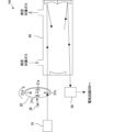
- FIG. 1 is an overall configuration diagram showing an example of a gas analyzer 100 according to this embodiment
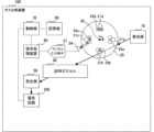
- FIG. 2 is a diagram showing an example of the outline of the gas analyzer 100 according to this embodiment.
- the gas analyzer 100 of this embodiment includes a light emitting unit 10, a gas filter wheel 20, a rotating mechanism 30, a sample gas cell 40, a light receiving unit 50, a signal processing device 60, a control unit 70, and an electric circuit 200.
- the gas analyzer 100 may include other components not shown in Figures 1 and 2.
- the gas filter wheel 20 includes multiple gas filters 21a-21d, position detection units 25a-25d, and a photodetector 26.
- the gas filter wheel 20 stores four gas filters 21a-21d. Note that the number of gas filters is not limited to four, and at least two or more can be stored.
- the light emitted from the light emitting unit 10 enters one of the gas filters 21a to 21d.
- the gas filters 21a to 21d are composed of cells that can be filled with gas.
- Zero gas e.g., N2 gas
- zero gas hereinafter also referred to as "gas type (A)"
- gas type (A) is filled in the gas filter 21a.
- the gas filters 21b to 21d other than the gas filter 21a in which zero gas is filled are filled with a plurality of high purity gases (hereinafter also referred to as "gas type ( B )", “gas type (C)”, and “gas type (D)”) of the measurement target gas (e.g., CO2 gas, etc.).
- the measurement target gas is filled in the gas filters 21b to 21d.
- the emitted light passes through one of the gas filters 21a to 21d, and a part of the light is absorbed by the gas component sealed in the gas filter 21a to 21d.
- the gas filter wheel 20 has a rotation mechanism 30.
- the gas filter wheel 20 is rotated in a predetermined direction by the drive of the rotation mechanism 30.
- the gas filter wheel 20 is rotated clockwise by the rotation mechanism 30 as shown by the arrow in FIG. 2.
- the gas filter wheel 20 may be rotated counterclockwise by the rotation mechanism 30.
- a general motor can be used for the rotation mechanism 30.
- the motor constituting the rotation mechanism 30 can rotate the gas filter wheel 20 at any rotation speed.
- the motor constituting the rotation mechanism 30 can rotate the gas filter wheel 20 at, for example, 1000 to 4000 rpm, and in this embodiment, can rotate the gas filter wheel 20 at 2000 rpm.
- the position detection units 25a to 25d detect the positions of the gas filters 21a to 21d in synchronization with the rotation of the gas filter wheel 20.
- the position detection units 25a to 25d are arranged near each of the gas filters 21a to 21d.
- the position detection units 25a to 25d are arranged radially inward of the gas filter wheel 20 with respect to each of the gas filters 21a to 21d.
- the gate signal is information indicating the position of each of the gas filters 21a to 21d corresponding to the position detection units 25a to 25d detected by the photodetector 26.
- the position detection units 25a to 25d are provided in the gas filter wheel 20 as holes corresponding to the filter numbers of each gas filter 21a to 21d.
- the position detection units 25a-25d of this embodiment are formed with a different number of holes for each of the gas filters 21a-21d.
- the gas filters 21a-21d are each formed with "1 hole” to "4 holes.”
- the number of holes is not limited to the embodiment shown in FIG. 1 and FIG. 2, and may be any number that allows each of the gas filters 21a-21d to be identified.
- the filter number can be set to a number that can uniquely identify each gas filter 21a to 21d.
- filter 1 to 4 can be set as the filter numbers of gas filters 21a to 21d, respectively.
- gas filters 21a to 21d may also be referred to as “filters 1 to 4.”
- Filters 1 to 4 are gas filters that correspond to gas types (A) to (D), respectively.
- the photodetector 26 can obtain information on the position of each of the gas filters 21a to 21d based on the gate signal corresponding to the position of the gas filters 21a to 21d detected by the position detectors 25a to 25d.
- the photodetector 26 obtains information on the position of the gas filter 21a by obtaining a single rising signal when passing through the position detector 25a corresponding to the gas filter 21a, and obtains information on the position of the gas filter 21b by obtaining two rising signals when passing through the position detector 25b corresponding to the gas filter 21b.
- the photodetector 26 obtains position information corresponding to the position of each gas filter 21a to 21d as a signal by combining the position detection units 25a to 25d with the photodetector 26, but this is not limited to the above. For example, it is sufficient to have the function of obtaining position information corresponding to the position of each gas filter 21a to 21d as a signal.
- a magnetic detection element not shown in the figure may return position information as a signal based on the magnetism emitted by the position detection units 25a to 25d.
- the position detection units 25a to 25d are formed by magnets that emit different magnetism for each gas filter 21a to 21d.
- the signal obtained by the photodetector 26 is input to the signal processing device 60 through the digital input terminal (Digital input) 51 as a synchronization signal (electrical signal).
- gas containing the gas to be measured flows through the sample gas cell 40.
- Light rays that pass through the gas filters 21a to 21d enter the sample gas cell 40.
- a multi-reflection cell may be used for the sample gas cell 40 in order to increase sensitivity.
- the light rays that pass through the sample gas cell 40 enter the light receiving unit 50.
- the light receiving unit 50 is equipped with a light receiving element (not shown).
- the light receiving element can be an element that is sensitive to both the light source and the gas to be measured, for example, an InAsSb photovoltaic element (P13243-022MS (manufactured by Hamamatsu Photonics)).
- P13243-022MS manufactured by Hamamatsu Photonics
- the light beam that passes through the gas filters 21a to 21d and the sample gas cell 40 and enters the light receiving unit 50 is input to the electrical circuit 200.
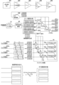
- FIG. 3 is a block diagram showing an example of the equipment configuration of the electrical circuit 200 that constitutes the gas analyzer 100.
- the electric circuit 200 includes a light receiving unit PD (photodiode) 201, an IV (current/voltage) conversion unit 202, an amplifier circuit (preamplifier circuit) 203, a low-pass filter (LPF: Low-pass Filter) 204, a band-pass filter (BPF: Band-pass Filter) 205, and an AD conversion unit 206.
- PD photodiode
- IV current/voltage
- LPF Low-pass Filter
- BPF Band-pass Filter
- the light receiving unit PD201 converts the amount of transmitted light that is incident from the light receiving unit 50 after passing through the gas filters 21a-21d and the sample gas cell 40 into a current (electrical signal) and causes it to flow into the electrical circuit 200.
- the IV conversion unit 202 converts the current flowing in by the light receiving unit PD201 into a voltage.
- the amplifier circuit 203 amplifies the output signal of the converted voltage. In this embodiment, the amplifier circuit 203 amplifies the output signal, but this is not limited to this. Amplification of the output signal by the amplifier circuit 203 may be omitted.
- the signal generated by the rotation of the motor that constitutes the rotating mechanism 30 is a square waveform signal (hereinafter also referred to as a "square wave signal"). Since the square wave signal contains many harmonic components, high frequency noise is removed by the low pass filter 204, and by passing only the necessary frequency bands and attenuating other frequencies by the band pass filter 205, components other than the frequency corresponding to the rotation of the motor that constitutes the rotating mechanism 30 are removed. This makes it possible to remove noise contained in the signal and improve the accuracy of gas concentration detection.
- the noise contained in the signal is removed by a combination of the low-pass filter 204 and the band-pass filter 205, but this is not limited to the above.
- the configuration of the low-pass filter 204 may be omitted and the noise contained in the signal may be removed only by the configuration of the band-pass filter 205.
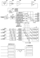
- FIG. 4 is a block diagram showing another example of the equipment configuration of the electric circuit 200 constituting the gas analyzer 100.
- the configuration of the low-pass filter 204 in the electric circuit 200 shown in FIG. 3 is omitted, and noise is removed by the band-pass filter 205. This simplifies the equipment configuration of the electric circuit 200 and reduces the manufacturing cost.
- the band-pass filter 205 may be replaced with a combination of a high-pass filter and a low-pass filter 204 (not shown) to remove noise contained in the signal.
- the AD conversion unit 206 digitizes the analog signal from which noise has been removed by the low-pass filter 204 and the band-pass filter 205, and outputs the digital signal.
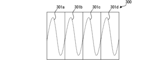
- FIG. 5 is a diagram showing an example of the digital signal after passing through the AD conversion unit 206. As shown in FIG. 5, the digital signal after passing through the AD conversion unit 206 is output as a continuous signal 300 including information on all signals 301a-301d of the gas filters 21a-21d. Note that in the descriptions of FIGS. 3 and 4, for convenience, the signals 301a-301d derived from the gas types (A)-(D) corresponding to the gas filters 21a-21d are illustrated using (1)-(4), respectively.
- the position information detected by the photodetector 26 is based on the rotation of the gas filter wheel 20. Therefore, when the motor constituting the rotation mechanism 30 rotates, the photodetector 26 can obtain a rising signal that corresponds to the position of each of the gas filters 21a to 21d. This signal is input to the signal processing device 60 as a digital signal from the digital input terminal 51. A comparator can be used as the input means.
- the signal processing device 60 generates a gate signal indicating the position of each gas filter 21a-21d based on the digitized synchronization signal (electrical signal) obtained by the photodetector 26.
- the control unit 70 provides overall control of the entire gas analyzer 100, and includes a CPU (Central Processing Unit) (not shown) that reads programs and executes gas concentration calculation processing.
- the memory unit 80 includes a RAM (Random Access Memory), a ROM (Read Only Memory), a HDD (Hard Disk Drive), an SSD (Solid State Drive), etc.
- the memory unit 80 stores the programs executed by the control unit 70 and various other data.
- the memory unit 80 also provides a working area for the control unit 70 when executing programs.
- the AD conversion unit 206 sequentially outputs signals (1) to (4) of gas types (A) to (D) corresponding to the gas filters 21a to 21d, and as shown in FIG. 5, the digital signal that has passed through the AD conversion unit 206 is output in the form of a continuous signal 300, like a continuous sine wave, that contains the information of all signals 301a to 301d of the gas filters 21a to 21d.
- the amplitude depends on the gas absorption, and the signals (1) to (4) of the gas types (A) to (D) each have a different amplitude.
- the signal processing device 60 generates a reference signal indicating the position of each gas filter 21a-21d based on the digitized synchronization signal (electrical signal) obtained by the photodetector 26.
- the reference signal is a signal used to synchronize the detected positions of the gas filters 21a-21d with the time information of the light rays transmitted through the gas filters 21a-21d.
- the synchronization signal generated in synchronization with the output from the gas filters 21a-21d is passed from the digital input terminal 51 through the signal processing device 60 to generate a gate signal and a reference signal.
- the gate signal generated by the signal processing device 60 is represented by a binary number, for example, ON or OFF.
- the gate signal detects the rotational position of each filter 1 to filter 4 based on the signal pattern of the synchronization signal (one ON or OFF signal for filter 1, two ON or OFF signals for filter 2, three ON or OFF signals for filter 3, and four ON or OFF signals for filter 4), and divides one rotation into four parts using the synchronization signal of filter 1 that comes after filter 4 as a trigger signal, and generates gate signal (1) that is ON during the sine wave of filter 1, gate signal (2) that is ON during the sine wave of filter 2, gate signal (3) that is ON during the sine wave of filter 3, and gate signal (4) that is ON during the sine wave of filter 4.
- the ON timing of each gate signal (1) to (4) must be determined taking into account the delay time of this bandpass filter 205.
- the reference signal may be a square wave or a sine wave digitally generated for four periods between the trigger signal and the next trigger signal, but as described above, the phase must be adjusted to take into account the effect of delay caused by the bandpass filter 205.
- the reference signal may be a sine wave or a square wave, but in the case of a square wave, the reference signal contains integer multiple harmonic components, making it impossible to narrow it down to a single frequency component by lock-in processing. In order to improve the SNR (signal-to-noise ratio), it is desirable to use a sine wave as the reference signal.
- the bandpass filter 205 it may be more advantageous to improve the SNR by widening the passband of the bandpass filter 205 to increase the signal amplitude. In that case, lock-in processing using a square wave as the reference signal is effective. Therefore, to perform the lock-in process, it is necessary to rearrange the continuous signal 300, which includes all the signals 301a-301d of the gas filters 21a-21d, into filter signals 401a-401d for each of the gas filters 21a-21d.
- the control unit 70 matches the continuous signal 300 including all the signals 301a to 301d of the gas filters 21a to 21d with the gate signal generated by the signal processing device 60, and divides the continuous signal 300 including all the signals 301a to 301d of the gas filters 21a to 21d to generate filter signals 401a to 401d for each of the gas filters 21a to 21d.
- the signal processing device 60 multiplies the gate signal indicating the position of each gas filter 21a to 21d (filters 1 to 4) by the signals 301a to 301d corresponding to each filter 1 to 4, respectively, to generate filter signals 401a to 401d corresponding to each gas filter 21a to 21d. In this way, the signal is separated into filter signals 401a to 401d by ANDing the gate signals (1) to (4) corresponding to the gas types (A) to (D).
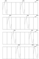
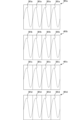
- FIG. 6 and 7 are diagrams showing an example of the generated filter signals 401a to 401d.
- the filter signals 401a to 401d corresponding to the gas filters 21a to 21d are generated by dividing them at predetermined timings as shown in FIG. 6, and are therefore generated as fragmentary sine waves that rise at predetermined timings. Therefore, the signal processing device 60 generates the generated fragmentary sine waves as continuous sine wave filter signals 401a to 401d as shown in FIG. 7. This allows each filter signal 401a to 401d to include a continuous sine wave signal corresponding to each gas filter 21a to 21d (filters 1 to 4).
- the separated filter signals 401a to 401d corresponding to each gas type (A) to (D) output signals at intervals of four signals.
- the envelope of this output continuous signal contains all of the absorption signals for each gas type (A) to (D), noise, etc.
- the control unit 70 performs gas concentration calculation processing on the output continuous signal by lock-in processing.
- the filter signals 401a to 401d are multiplied by a reference signal by multipliers 71a to 71d, and passed through digital LPFs 72a to 72d to output each signal component with DC components remaining, including the absorption signals of each gas type.
- the noise components of each filter signal 401a to 401d are removed by the digital LPFs 72a to 72d, allowing the control unit 70 to obtain signal components with a good SNR (Signal-to-Noise Ratio).
- each signal component output after the lock-in process contains disturbance factors such as temperature changes, pressure changes, and light source fluctuations at each time.
- Equation 1 is an example of the principle equation of the gas filter correlation method when the measurement component gas is CO.
- the light that passes through the N2 filter includes absorption by the measurement target gas in the gas filter, and the signal that passes through the filter containing the measurement target gas ideally absorbs all of the absorption by the measurement target gas in the filter, so a signal is output regardless of the concentration of the measurement target gas present inside the downstream gas cell.
- the signal that passes through the N2 gas filter + sample gas cell 40 by taking the difference in signal level between the signal that passes through the N2 gas filter + sample gas cell 40 and the signal that passes through the measurement target gas gas filter + sample gas cell 40, it is possible to remove noise components common to both paths.
- Equation 1 The value calculated by Equation 1 is proportional to the gas concentration according to the Beer-Lambert law. By performing zero-span calibration using a specified method, the gas concentration indication value for each gas type (A) to (D) can be calculated.
- the lock-in process is executed by the control unit 70, but this is not limited to the above.
- the lock-in process may be executed by a general-purpose PC (not shown) connected to the gas analyzer 100. This allows the control unit 70 of the gas analyzer 100 to be configured simply, thereby reducing costs.
Landscapes
- Physics & Mathematics (AREA)
- Spectroscopy & Molecular Physics (AREA)
- Health & Medical Sciences (AREA)
- Life Sciences & Earth Sciences (AREA)
- Chemical & Material Sciences (AREA)
- Analytical Chemistry (AREA)
- Biochemistry (AREA)
- General Health & Medical Sciences (AREA)
- General Physics & Mathematics (AREA)
- Immunology (AREA)
- Pathology (AREA)
- Investigating Or Analysing Materials By Optical Means (AREA)
Abstract
Description

20 :ガスフィルタホイール
21a~21d :ガスフィルタ
25a~25d :位置検知部
26 :フォトディテクタ
30 :回転機構
40 :試料ガスセル
50 :受光部
51 :デジタル入力端子
60 :信号処理装置
70 :制御部
71a~71d :乗算器
72a~72d :デジタルLPF
80 :記憶部
100 :ガス分析装置
200 :電気回路
201 :受光部PD
202 :IV変換部
203 :アンプ回路
204 :ローパスフィルタ
205 :バンドパスフィルタ
206 :AD変換部
300 :連続信号
301a~301d :信号
401a~401d :フィルタ信号
Claims (6)
- 赤外光線を射出する光源と、
前記光源からの光線を透過し、高純度の複数の測定対象ガス及び赤外光に吸収を持たない1つのガスが封入された複数のガスフィルタと、
複数の前記ガスフィルタが格納され、回転機構を有するガスフィルタホイールと、
前記ガスフィルタを透過した光線が入射し、測定対象ガスを含むガスが流通する試料ガスセルと、
前記試料ガスセルを透過した赤外光線を受光する受光部と、
を備えたガス分析装置。 - 前記受光部で受光した赤外光を電気信号に変換し、ガス濃度演算する信号処理装置と、
前記ガスフィルタホイールの回転に同期し、前記複数のガスフィルタの位置を検出する位置検知部と、
制御部と、を更に備え、
前記制御部は、
検出した前記ガスフィルタの位置と前記ガスフィルタを透過した光線の時間情報を同期し、
前記ガスフィルタ毎にガス濃度算出処理を行う
ことを特徴とする請求項1に記載のガスフィルタ相関方式(GFC:Gas Filter Correlation)のガス分析装置。 - 前記位置検知部の位置を検知するフォトディテクタを更に備え、
前記位置検知部は、前記ガスフィルタの位置毎に異なる数の穴により形成されている
ことを特徴とする請求項2に記載のガス分析装置。 - 前記位置検知部の位置を検知する磁気検出素子を更に備え、
前記位置検知部は、前記ガスフィルタの位置毎に異なる磁気を発する磁石により形成されている
ことを特徴とする請求項2に記載のガス分析装置。 - 前記制御部は、
同期信号を参照信号とゲート信号のANDを取って分離し、分離した前記同期信号を更につなぎ合わせて連続信号に並べる信号処理を行い、
前記連続信号をロックイン処理によって前記ガス濃度算出処理を行う
ことを特徴とする請求項2から4のうち何れかに記載のガス分析装置。 - 前記制御部は、前記測定対象ガスが封入された前記ガスフィルタの前記連続信号の信号成分の信号レベルと、参照ガスが封入された前記ガスフィルタの前記連続信号の信号成分の信号レベルと、を比較して、所定のガスフィルタ相関法の原理式に基づき、前記測定対象ガスの各ガス濃度指示値をそれぞれ算出する
ことを特徴とする請求項5に記載のガス分析装置。
Priority Applications (1)
| Application Number | Priority Date | Filing Date | Title |
|---|---|---|---|
| EP24764012.1A EP4563976A4 (en) | 2023-03-02 | 2024-02-29 | GAS ANALYSIS DEVICE |
Applications Claiming Priority (2)
| Application Number | Priority Date | Filing Date | Title |
|---|---|---|---|
| JP2023-031563 | 2023-03-02 | ||
| JP2023031563A JP7439974B1 (ja) | 2023-03-02 | 2023-03-02 | ガス分析装置 |
Publications (1)
| Publication Number | Publication Date |
|---|---|
| WO2024181535A1 true WO2024181535A1 (ja) | 2024-09-06 |
Family
ID=90011299
Family Applications (1)
| Application Number | Title | Priority Date | Filing Date |
|---|---|---|---|
| PCT/JP2024/007550 Ceased WO2024181535A1 (ja) | 2023-03-02 | 2024-02-29 | ガス分析装置 |
Country Status (3)
| Country | Link |
|---|---|
| EP (1) | EP4563976A4 (ja) |
| JP (1) | JP7439974B1 (ja) |
| WO (1) | WO2024181535A1 (ja) |
Cited By (1)
| Publication number | Priority date | Publication date | Assignee | Title |
|---|---|---|---|---|
| CN121141568A (zh) * | 2025-09-23 | 2025-12-16 | 济南德尔姆仪器有限公司 | 一种智能传感多通道泵吸式气体检测仪及其使用方法 |
Families Citing this family (1)
| Publication number | Priority date | Publication date | Assignee | Title |
|---|---|---|---|---|
| US20260063542A1 (en) * | 2024-08-29 | 2026-03-05 | Fuji Electric Co., Ltd. | Gas correlation filter wheel and gas analyzer |
Citations (10)
| Publication number | Priority date | Publication date | Assignee | Title |
|---|---|---|---|---|
| JPS5453579A (en) * | 1977-10-05 | 1979-04-26 | Fujitsu Ltd | Infrared ray multicomponent gas analysis apparatus |
| JPS5634814B2 (ja) * | 1973-05-10 | 1981-08-13 | ||
| JPH0135292B2 (ja) * | 1984-01-17 | 1989-07-25 | Yamatake Honeywell Co Ltd | |
| JPH0815128A (ja) * | 1994-06-27 | 1996-01-19 | Horiba Ltd | 自動周波数調整装置 |
| JPH0833349B2 (ja) * | 1986-07-31 | 1996-03-29 | 株式会社島津製作所 | 赤外線式ガス分析計 |
| JPH1048135A (ja) * | 1996-07-31 | 1998-02-20 | Shimadzu Corp | 赤外線ガス分析装置 |
| JPH1082740A (ja) * | 1996-09-06 | 1998-03-31 | Shimadzu Corp | 赤外線式ガス分析計 |
| JP4790330B2 (ja) | 2005-06-22 | 2011-10-12 | 東亜ディーケーケー株式会社 | ガス濃度測定装置 |
| EP3163291A1 (de) * | 2016-12-02 | 2017-05-03 | Sick Ag | Messgerät zur bestimmung von konzentrationen mehrerer gaskomponenten |
| JP2023031563A (ja) | 2021-08-25 | 2023-03-09 | 国立大学法人北海道大学 | 塩分含有水氷及び/又は水氷の製造量算出装置、塩分含有水氷及び/又は水氷の製造量算出方法、及び、塩分含有水氷及び/又は水氷の製造量算出装置を備えた塩分含有水氷及び/又は水氷製造装置 |
Family Cites Families (5)
| Publication number | Priority date | Publication date | Assignee | Title |
|---|---|---|---|---|
| US6744516B2 (en) * | 2001-08-21 | 2004-06-01 | Spx Corporation | Optical path structure for open path emissions sensing |
| CN101281125B (zh) * | 2008-05-19 | 2011-09-07 | 安徽敏测光电科技有限公司 | 一种智能红外多组分有害气体监测方法和装置 |
| KR101014245B1 (ko) * | 2008-11-11 | 2011-02-16 | 한국표준과학연구원 | 멀티가스필터를 갖는 비분산적외선 검출기를 이용한 다종오염물질 측정장치 및 방법 |
| KR101041768B1 (ko) * | 2009-04-10 | 2011-06-17 | (주)켄텍 | 일산화탄소-이산화탄소 성분 동시 측정 장치 |
| KR102435342B1 (ko) * | 2021-12-22 | 2022-08-23 | (주)켄텍 | 다중 대기 오염 가스 동시 측정장치 |
-
2023
- 2023-03-02 JP JP2023031563A patent/JP7439974B1/ja active Active
-
2024
- 2024-02-29 WO PCT/JP2024/007550 patent/WO2024181535A1/ja not_active Ceased
- 2024-02-29 EP EP24764012.1A patent/EP4563976A4/en active Pending
Patent Citations (10)
| Publication number | Priority date | Publication date | Assignee | Title |
|---|---|---|---|---|
| JPS5634814B2 (ja) * | 1973-05-10 | 1981-08-13 | ||
| JPS5453579A (en) * | 1977-10-05 | 1979-04-26 | Fujitsu Ltd | Infrared ray multicomponent gas analysis apparatus |
| JPH0135292B2 (ja) * | 1984-01-17 | 1989-07-25 | Yamatake Honeywell Co Ltd | |
| JPH0833349B2 (ja) * | 1986-07-31 | 1996-03-29 | 株式会社島津製作所 | 赤外線式ガス分析計 |
| JPH0815128A (ja) * | 1994-06-27 | 1996-01-19 | Horiba Ltd | 自動周波数調整装置 |
| JPH1048135A (ja) * | 1996-07-31 | 1998-02-20 | Shimadzu Corp | 赤外線ガス分析装置 |
| JPH1082740A (ja) * | 1996-09-06 | 1998-03-31 | Shimadzu Corp | 赤外線式ガス分析計 |
| JP4790330B2 (ja) | 2005-06-22 | 2011-10-12 | 東亜ディーケーケー株式会社 | ガス濃度測定装置 |
| EP3163291A1 (de) * | 2016-12-02 | 2017-05-03 | Sick Ag | Messgerät zur bestimmung von konzentrationen mehrerer gaskomponenten |
| JP2023031563A (ja) | 2021-08-25 | 2023-03-09 | 国立大学法人北海道大学 | 塩分含有水氷及び/又は水氷の製造量算出装置、塩分含有水氷及び/又は水氷の製造量算出方法、及び、塩分含有水氷及び/又は水氷の製造量算出装置を備えた塩分含有水氷及び/又は水氷製造装置 |
Non-Patent Citations (1)
| Title |
|---|
| See also references of EP4563976A4 |
Cited By (1)
| Publication number | Priority date | Publication date | Assignee | Title |
|---|---|---|---|---|
| CN121141568A (zh) * | 2025-09-23 | 2025-12-16 | 济南德尔姆仪器有限公司 | 一种智能传感多通道泵吸式气体检测仪及其使用方法 |
Also Published As
| Publication number | Publication date |
|---|---|
| JP2024123830A (ja) | 2024-09-12 |
| JP7439974B1 (ja) | 2024-02-28 |
| EP4563976A4 (en) | 2025-12-03 |
| EP4563976A1 (en) | 2025-06-04 |
Similar Documents
| Publication | Publication Date | Title |
|---|---|---|
| WO2024181535A1 (ja) | ガス分析装置 | |
| CN103842801B (zh) | 具有用于气体测量的多个源的红外传感器 | |
| FI69370B (fi) | Foerfarande foer maetning av egenskaperna hos ett plastskikt med hjaelp av infraroed straolning | |
| US20180238735A1 (en) | Spatially variable light source and spatially variable detector systems and methods | |
| US4084906A (en) | Multigas digital correlation spectrometer | |
| CN101231240A (zh) | 测量一氧化碳浓度的仪器及方法 | |
| CN114062286B (zh) | 气体分析系统及气体分析方法 | |
| CN102171548A (zh) | 适于对高浓度气体进行光谱分析的设备 | |
| US7288766B2 (en) | Infrared gas detector and method of the same | |
| JP2011149718A (ja) | ガス分析装置 | |
| KR20170052256A (ko) | 라만 산란을 이용한 물질의 농도 측정 장치 및 방법 | |
| US20050247878A1 (en) | Infrared gas sensor | |
| US20100078560A1 (en) | Gas detector | |
| JPH06249779A (ja) | ガス分析計 | |
| US4605313A (en) | Infrared detector for NDIR gas analysis | |
| WO2015122237A1 (ja) | 分光分析装置および分光分析方法 | |
| JPS61194332A (ja) | ガス濃度を測定する方法およびこの方法を実施するための装置 | |
| JPS59208445A (ja) | 試料の吸収性成分量を測定するための方法とその装置 | |
| NL7908629A (nl) | Inrichting voor het met behulp van straling detecteren van bestanddelen in gassen. | |
| JP2019536058A (ja) | 流体分析のためのシステム及び方法 | |
| WO2011160412A1 (zh) | 适用于光电检测的差分测量方法及装置 | |
| JP2004020539A (ja) | 赤外円二色性測定装置および赤外円二色性測定方法 | |
| JP4790330B2 (ja) | ガス濃度測定装置 | |
| JP6530669B2 (ja) | ガス濃度測定装置 | |
| JP2015227858A5 (ja) |
Legal Events
| Date | Code | Title | Description |
|---|---|---|---|
| 121 | Ep: the epo has been informed by wipo that ep was designated in this application |
Ref document number: 24764012 Country of ref document: EP Kind code of ref document: A1 |
|
| WWE | Wipo information: entry into national phase |
Ref document number: 2024764012 Country of ref document: EP Ref document number: 24764012.1 Country of ref document: EP |
|
| ENP | Entry into the national phase |
Ref document number: 2024764012 Country of ref document: EP Effective date: 20250227 |
|
| WWP | Wipo information: published in national office |
Ref document number: 2024764012 Country of ref document: EP |
|
| NENP | Non-entry into the national phase |
Ref country code: DE |