WO2024190768A1 - Procédé de production de solution de substance inorganique et appareil de production de solution de substance inorganique - Google Patents
Procédé de production de solution de substance inorganique et appareil de production de solution de substance inorganique Download PDFInfo
- Publication number
- WO2024190768A1 WO2024190768A1 PCT/JP2024/009499 JP2024009499W WO2024190768A1 WO 2024190768 A1 WO2024190768 A1 WO 2024190768A1 JP 2024009499 W JP2024009499 W JP 2024009499W WO 2024190768 A1 WO2024190768 A1 WO 2024190768A1
- Authority
- WO
- WIPO (PCT)
- Prior art keywords
- heating
- inorganic
- inorganic substance
- mixture
- additive
- Prior art date
- Legal status (The legal status is an assumption and is not a legal conclusion. Google has not performed a legal analysis and makes no representation as to the accuracy of the status listed.)
- Ceased
Links
Images







Classifications
-
- C—CHEMISTRY; METALLURGY
- C01—INORGANIC CHEMISTRY
- C01D—COMPOUNDS OF ALKALI METALS, i.e. LITHIUM, SODIUM, POTASSIUM, RUBIDIUM, CAESIUM, OR FRANCIUM
- C01D15/00—Lithium compounds
- C01D15/02—Oxides; Hydroxides
-
- C—CHEMISTRY; METALLURGY
- C22—METALLURGY; FERROUS OR NON-FERROUS ALLOYS; TREATMENT OF ALLOYS OR NON-FERROUS METALS
- C22B—PRODUCTION AND REFINING OF METALS; PRETREATMENT OF RAW MATERIALS
- C22B1/00—Preliminary treatment of ores or scrap
- C22B1/02—Roasting processes
-
- C—CHEMISTRY; METALLURGY
- C22—METALLURGY; FERROUS OR NON-FERROUS ALLOYS; TREATMENT OF ALLOYS OR NON-FERROUS METALS
- C22B—PRODUCTION AND REFINING OF METALS; PRETREATMENT OF RAW MATERIALS
- C22B26/00—Obtaining alkali, alkaline earth metals or magnesium
- C22B26/10—Obtaining alkali metals
- C22B26/12—Obtaining lithium
-
- C—CHEMISTRY; METALLURGY
- C22—METALLURGY; FERROUS OR NON-FERROUS ALLOYS; TREATMENT OF ALLOYS OR NON-FERROUS METALS
- C22B—PRODUCTION AND REFINING OF METALS; PRETREATMENT OF RAW MATERIALS
- C22B3/00—Extraction of metal compounds from ores or concentrates by wet processes
-
- C—CHEMISTRY; METALLURGY
- C22—METALLURGY; FERROUS OR NON-FERROUS ALLOYS; TREATMENT OF ALLOYS OR NON-FERROUS METALS
- C22B—PRODUCTION AND REFINING OF METALS; PRETREATMENT OF RAW MATERIALS
- C22B3/00—Extraction of metal compounds from ores or concentrates by wet processes
- C22B3/04—Extraction of metal compounds from ores or concentrates by wet processes by leaching
- C22B3/06—Extraction of metal compounds from ores or concentrates by wet processes by leaching in inorganic acid solutions, e.g. with acids generated in situ; in inorganic salt solutions other than ammonium salt solutions
-
- C—CHEMISTRY; METALLURGY
- C22—METALLURGY; FERROUS OR NON-FERROUS ALLOYS; TREATMENT OF ALLOYS OR NON-FERROUS METALS
- C22B—PRODUCTION AND REFINING OF METALS; PRETREATMENT OF RAW MATERIALS
- C22B3/00—Extraction of metal compounds from ores or concentrates by wet processes
- C22B3/04—Extraction of metal compounds from ores or concentrates by wet processes by leaching
- C22B3/12—Extraction of metal compounds from ores or concentrates by wet processes by leaching in inorganic alkaline solutions
-
- C—CHEMISTRY; METALLURGY
- C22—METALLURGY; FERROUS OR NON-FERROUS ALLOYS; TREATMENT OF ALLOYS OR NON-FERROUS METALS
- C22B—PRODUCTION AND REFINING OF METALS; PRETREATMENT OF RAW MATERIALS
- C22B4/00—Electrothermal treatment of ores or metallurgical products for obtaining metals or alloys
- C22B4/02—Light metals
Definitions
- the present invention relates to a method for producing an inorganic solution and an apparatus for producing an inorganic solution.
- lithium ores include spodumene (LiAlSi2O6), lepidolite (K(Al , Li) 2 (Si,Al) 4O10 ( OH ,F) 2 ) , petalite (LiAlSi4O10), elbaite ( Na (Li,Al) 3Al6 ( BO3 )3Si6O18 ( OH) 4 ) , and hectorite ( Na0.3 (Mg, Li ) 3Si4O10 ( OH)2 ) .
- the lithium When recovering lithium from lithium ore, the lithium is extracted from the lithium ore by dissolving the ore in a solvent. However, it is not easy to dissolve lithium ore in a solvent.
- Non-Patent Document 1 uses a method in which lithium ore is calcined at 1000°C or higher, and then roasted at 250°C using concentrated sulfuric acid.
- Patent Document 1 also uses a method in which lithium ore is mixed with a small amount of calcium oxide, heated at 1000 to 1300°C, and then dissolved using an acid solution at 400°C and under pressure.
- the amount of calcium oxide mixed with the lithium ore is 0.08 or more and less than 0.34 in molar ratio to the amount of lithium ore.
- the pressure in the dissolution process is 90 atmospheres or more.
- the dissolution process for dissolving lithium ore in an acid solution required heating to 250°C or 400°C. Furthermore, in the conventional technique described in Patent Document 1, in addition to heating, the dissolution process required pressurization to a high pressure of 90 atmospheres or more.
- the invention according to one aspect of the present invention was made in consideration of the above-mentioned problems, and its purpose is to provide a technology that can dissolve inorganic substances such as lithium ores more easily than the conventional technology described in Non-Patent Document 1 and Patent Document 1.
- a method for producing an inorganic solution includes a mixing step of obtaining a first mixture by mixing an inorganic substance that undergoes a phase change or thermal decomposition upon heating with an additive that is at least one of an alkali metal hydroxide, an alkaline earth metal hydroxide, and an alkaline earth metal oxide, and a heating step of obtaining a second mixture of the inorganic substance and the additive by heating the first mixture at a heating temperature that is equal to or higher than a predetermined temperature.
- the ratio of the additive to the inorganic substance in the mixing step is 0.5 or more in molar ratio
- the predetermined temperature is (1) a temperature at which the phase change occurs if the inorganic substance is an inorganic substance that undergoes a phase change upon heating, and (2) a temperature at which the thermal decomposition occurs if the inorganic substance is an inorganic substance that undergoes thermal decomposition upon heating.
- a method for producing an inorganic solution includes a phase change step of heating an inorganic substance that undergoes a phase change to cause a phase change, a mixing step of obtaining a first mixture by mixing the inorganic substance that has undergone a phase change with an additive that is at least one of an alkali metal hydroxide, an alkaline earth metal hydroxide, and an alkaline earth metal oxide, and a heating step of obtaining a second mixture of the inorganic substance and the additive by heating the first mixture.
- a molar ratio of the additive to the inorganic substance in the mixing step is 0.5 or more.
- a method for producing an inorganic solution includes a mixing step of obtaining a first mixture by mixing an inorganic substance containing ⁇ -spodumene with an additive that is at least one of an alkali metal hydroxide, an alkaline earth metal hydroxide, and an alkaline earth metal oxide, and a heating step of obtaining a second mixture of the inorganic substance and the additive by heating the first mixture.
- a molar ratio of the additive to the inorganic substance in the mixing step is 0.5 or more.
- an inorganic solution manufacturing apparatus includes a mixing section for obtaining a first mixture by mixing an inorganic substance that undergoes a phase change or thermal decomposition upon heating with an additive that is at least one of an alkali metal hydroxide, an alkaline earth metal hydroxide, and an alkaline earth metal oxide, and a heating section for obtaining a second mixture of the inorganic substance and the additive by heating the first mixture at a heating temperature that is equal to or higher than a predetermined temperature.
- the ratio of the additive to the inorganic substance in the mixing section is 0.5 or more in molar ratio
- the predetermined temperature is (1) the temperature at which the phase change occurs if the inorganic substance is an inorganic substance that undergoes a phase change upon heating, and (2) the temperature at which the thermal decomposition occurs if the inorganic substance is an inorganic substance that undergoes thermal decomposition upon heating.
- a technology can be provided that can dissolve inorganic materials such as lithium ores more easily than the conventional technology described in Non-Patent Document 1 and Patent Document 1.
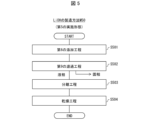
- FIG. 1 is a flowchart showing a method for producing an inorganic solution according to a first embodiment of the present invention.
- 5 is a flowchart showing a method for producing an inorganic solution according to a second embodiment of the present invention.
- 10 is a flowchart showing a method for producing an inorganic solution according to a third embodiment of the present invention.
- 10 is a flowchart showing a method for producing an inorganic solution according to a fourth embodiment of the present invention.
- 10 is a flowchart showing a method for producing an inorganic solution according to a fifth embodiment of the present invention.
- FIG. 13 is a schematic diagram of a dielectric heating device according to a sixth embodiment of the present invention.
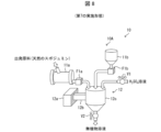
- FIG. 13 is a schematic diagram of an inorganic solution manufacturing apparatus provided in an inorganic solution manufacturing system according to a seventh embodiment of the present invention.
- 1 is a photograph showing the mixture after heating obtained in the first example.
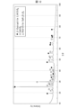
- 1 is a graph showing the results of an X-ray diffraction (XRD) test of inorganic substances contained in the mixture after heating obtained in the first example.
- 1 is a graph showing the results of an XRD test of inorganic substances contained in a solid phase of an inorganic substance solution obtained in the first example.
- 11 is a graph showing the results of an XRD test of inorganic substances contained in the mixture obtained after heating in the second example.
- 13 is a graph showing the relationship between the elution rate of lithium in the inorganic solution obtained in the third embodiment and the weight ratio of natural spodumene and calcium carbonate.
- FIG. 1 is a flow chart of the method for producing an inorganic solution M10.
- the method for producing an inorganic solution M10 will also be simply referred to as the production method M10.
- the inorganic solution means a solution in which an inorganic substance, which is a starting material, is dissolved.
- the inorganic substance is a general term for inorganic compounds and metals.
- the inorganic compound refers to a compound other than an organic substance or an organic compound, that is, a compound that does not contain carbon.
- the inorganic compound contains a metal such as lithium ore, rare metal, or rare earth, which will be described later.
- the metal contains a precious metal.
- the precious metal includes gold (Au), silver (Ag), and platinum metals (ruthenium (Ru), rhodium (Rh), palladium (Pd), osmium (Os), iridium (Ir), and platinum (Pt)).
- lithium ore containing natural spodumene is used as the inorganic material used in manufacturing method M10.
- Spodumene is an example of a lithium ore that exists in nature.
- Natural spodumene is divided into ⁇ -phase and ⁇ -phase depending on the crystal structure.
- ⁇ -phase and ⁇ -phase spodumene are referred to as ⁇ -spodumene and ⁇ -spodumene, respectively.
- Most natural spodumene obtained from mines is ⁇ -spodumene.
- spodumene undergoes a phase change to ⁇ -spodumene when heated at a temperature of 1000°C or higher.
- the inorganic substance used in the manufacturing method M10 is not limited to natural spodumene-containing ores, and may be appropriately selected from inorganic substances whose crystal structure undergoes a phase change or thermal decomposition upon heating.
- An example of an inorganic substance that undergoes thermal decomposition upon heating is petalite (LiAlSi 4 O 10 ).
- manufacturing method M10 includes a grinding and mixing step S101, a heating step S102, and a dissolving step S103.
- an inorganic material is pulverized to obtain an inorganic powder.
- the inorganic material is mechanically broken down to reduce the particle size, thereby improving the efficiency of the chemical reaction with the hydroxide or oxide.
- the technique used to pulverize the inorganic material is not limited and can be appropriately selected from existing techniques, for example, a jaw crusher or a ball mill.
- sodium hydroxide which is an example of an additive
- NaOH sodium hydroxide
- the step of pulverizing sodium hydroxide in the pulverizing/mixing step S101 may be omitted.
- the sodium hydroxide used in the pulverizing/mixing step S101 is granular or flaky
- the pulverization of sodium hydroxide in the pulverizing/mixing step S101 may be omitted.
- the shape of the sodium hydroxide used in the pulverizing/mixing step S101 is not limited. Note that sodium hydroxide is an example of a hydroxide.
- At least one of the hydroxides and oxides used in the manufacturing method M10 is not limited to sodium hydroxide, and may be calcium hydroxide (Ca(OH) 2 ) or calcium oxide (CaO).
- a plurality of sodium hydroxide, calcium hydroxide, and calcium oxide may be selected and combined.
- the ground inorganic substance and the ground additive are mixed to obtain a mixture of the inorganic substance and the additive.
- the mixture obtained in the grinding and mixing step S101 is an example of the first mixture.
- this mixture is in a powder form.
- the ratio of the additive to the inorganic substance is 0.5 or more in molar ratio.
- the ratio of the additive to the inorganic substance is expressed using a molar ratio unless otherwise specified.
- ⁇ -spodumene used as the inorganic substance and sodium hydroxide used as the additive react with each other in a ratio of 1:1 to generate lithium metasilicate (Li 2 SiO 3 ) that is easily dissolved in acid or water.
- this ratio is preferably 0.8 to 4, and more preferably 1 to 2.
- the heating step S102 is a step of obtaining a mixture of a phase-changed or thermally decomposed inorganic substance and an additive by heating the mixture obtained in the crushing and mixing step S101 at a heating temperature equal to or higher than a predetermined temperature.
- the predetermined temperature in the heating step S102 is (1) a temperature at which the phase change occurs if the inorganic substance is an inorganic substance that undergoes a phase change upon heating, or (2) a temperature at which the thermal decomposition occurs if the inorganic substance is an inorganic substance that undergoes thermal decomposition upon heating.
- the mixture obtained in the heating step S102 is an example of a second mixture.
- the mixture (first mixture) is heated to a temperature at which a phase change or thermal decomposition of the crystalline structure occurs in the inorganic substance.
- dielectric heating is used as the heating method in the heating step S102
- 700°C is used as the heating temperature.
- This heating temperature is equal to or higher than the temperature at which ⁇ -spodumene changes phase (i.e., the predetermined temperature).
- a radiation thermometer is used to measure the temperature of the mixture during dielectric heating.
- the heating temperature here is the temperature of the surface of the mixture measured using the radiation thermometer. Therefore, the inside of the mixture during heating may reach a temperature higher than 700°C.
- the heating temperature is not limited to 700°C, and can be set appropriately within the temperature range at which a phase change or thermal decomposition occurs in the inorganic material.
- the heating time can be set appropriately within the range at which the reaction described below proceeds sufficiently. By increasing the heating temperature, it is highly likely that the heating time can be shortened.
- the sodium hydroxide and the inorganic matter convert the energy of the electromagnetic waves, which will be described later, into thermal energy and are heated.
- the natural spodumene i.e., ⁇ -spodumene
- the inorganic matter undergoes a phase change to ⁇ -spodumene.
- ⁇ -spodumene reacts with sodium hydroxide in a 1:1 ratio to produce silica (NaAlSiO 4 ), Li 2 SiO 3 , and quartz (SiO 2 ).
- the mixture can be dielectrically heated under normal pressure.
- At least one of the starting material and the additive may contain moisture. If at least one of the starting material and the additive contains moisture, drying (boiling and evaporation of moisture) begins when the heating temperature reaches 100°C, and further heating is performed after all the moisture has evaporated. In this way, heating can be performed under normal pressure even if moisture is contained.
- Dielectric heating is a general term for a technology that heats an object by applying electromagnetic waves of a specific frequency to the object, and is also called high-frequency heating or microwave heating depending on the band of the electromagnetic waves applied.
- high-frequency heating applies electromagnetic waves in the band of 3 MHz or more and less than 300 MHz (so-called short waves or ultra-short waves) to an object
- microwave heating applies electromagnetic waves in the band of 300 MHz or more and less than 30 GHz (so-called microwaves) to an object.
- microwave ovens which are widely used in homes, are one example of a device that can perform microwave heating.
- electromagnetic waves with a frequency of 2.45 GHz are applied to the mixture.
- the configuration of the device that applies electromagnetic waves to the powdered mixture will be described later with reference to FIG. 6 or FIG. 8.
- manufacturing method M10 can provide a manufacturing method for an inorganic matter solution that can be more easily dissolved in an acid solution than conventional manufacturing methods.
- the heating method used in heating step S102 may be external heating instead of dielectric heating.
- the concentration of the acid solution is not particularly limited, and it is sufficient that the acid solution has a concentration at which the inorganic matter dissolves.
- the dissolving step S103 is a step of dissolving the mixture obtained in the heating step S102 in an acid solution or water to obtain a solution of inorganic substances contained in the starting materials.
- sulfuric acid H2SO4
- H2SO4 sulfuric acid
- a sulfuric acid solution in which Li2SO4 , Al2 ( SO4 ) 3 , H2SiO3 , and Na2SO4 are dissolved is obtained .
- the acid solution used in the dissolving step S103 is not limited to a sulfuric acid solution, but may be at least one of a hydrochloric acid solution, a nitric acid solution, a hydrofluoric acid solution, a hydrobromic acid solution, and a hydroiodic acid solution, or may be a mixed acid solution obtained by mixing a plurality of these acid solutions.
- An example of such a mixed acid solution is aqua regia obtained by mixing concentrated hydrochloric acid and concentrated nitric acid.
- water can also be used as the liquid for dissolving the heated mixture obtained in the heating step S102.
- the mixture obtained in the heating step S102 dissolves in a sulfuric acid solution at room temperature and pressure.
- the sulfuric acid solution may be heated or pressurized.
- a suitable means for heating the sulfuric acid solution is a device that applies electromagnetic waves, as used in the heating step S102.
- the dissolving step S103 in order to prevent the sulfuric acid solution from boiling, it is preferable to set the temperature of the sulfuric acid solution to less than 250 degrees (corresponding to the boiling point of concentrated sulfuric acid). This makes it unnecessary to pressurize the sulfuric acid solution, and the dissolving step S103 can be carried out under normal pressure.
- the crushing and mixing step S101 natural spodumene is crushed to obtain an inorganic powder.
- Calcium oxide is crushed to obtain calcium oxide powder.
- the crushed inorganic material and the crushed additive are mixed to obtain a mixture of the inorganic material and the additive (first mixture).
- the molar ratio of the additive to the inorganic material is 0.5 or more.
- the shape of the calcium oxide is not limited to a powder.
- ⁇ -spodumene used as the inorganic substance and calcium oxide used as the additive react in a 1:1 ratio to produce ⁇ -eucryptite (LiAlSiO 4 ), which is easily soluble in acid or water. If the ratio of additive to inorganic substance is set too high above 1, a large amount of additive will not be used in the reaction that converts ⁇ -spodumene to ⁇ -eucryptite, i.e., more additive will be wasted. Therefore, this ratio is preferably 0.8 to 4, and more preferably 1 to 2.
- the mixture is heated to a temperature at which a phase change of the crystal structure occurs in the inorganic substance.
- external heating is used as the heating method in the heating step S102, and 1050° C. is used as the heating temperature.
- the heating temperature during external heating is measured using a thermometer attached to the furnace used for external heating. Therefore, the temperature of the mixture is considered to be almost uniform regardless of its surface or inside.
- the mixture of the starting material powder and calcium oxide powder is externally heated to 1050° C., thereby causing a phase change from natural spodumene ( ⁇ -spodumene) to ⁇ -spodumene. Furthermore, ⁇ -eucryptite and CaSiO 3 are produced from ⁇ -spodumene. Note that in the heating step S102, dielectric heating may be used instead of external heating.
- the dissolving step S103 in this modification is the same as the dissolving step S103 in the case where sodium hydroxide is used as the additive. Therefore, in this modification , the description thereof is omitted.
- a sulfuric acid solution in which Li2SO4 , CaSO4 , H2SiO3 , and Al2 ( SO4 ) 3 are dissolved is obtained .
- an inorganic solution can be easily produced by using calcium oxide as an additive.
- one aspect of the present invention may include a mixing step of mixing an inorganic substance containing ⁇ -spodumene with the additive described above to obtain a mixture (first mixture), and a heating step of heating the mixture to obtain a mixture of the inorganic substance and the additive (second mixture).
- the molar ratio of the additive to the inorganic substance in the mixing step is also 0.5 or more.
- Fig. 2 is a flow chart of the method for producing an inorganic solution M20.
- the method for producing an inorganic solution M20 will also be simply referred to as the production method M20.
- manufacturing method M20 includes a grinding step S201, a phase change step S202, a mixing step S203, a heating step S204, and a dissolving step S205.
- an inorganic substance is pulverized to obtain an inorganic powder.
- natural spodumene is used as the inorganic substance used in the manufacturing method M20.
- sodium hydroxide (NaOH) is pulverized to obtain a sodium hydroxide powder.
- the pulverizing method can be performed by the method described in the pulverizing/mixing step S101 of the manufacturing method M10.
- phase change process In the phase change step S202, the inorganic powder obtained in the pulverization step S201 is heated to change the phase.
- natural spodumene ( ⁇ -spodumene) contained in the inorganic substance is subjected to dielectric heating to change the phase to ⁇ -spodumene.
- the heating method used in the phase change step S202 the method described in the heating step S102 of the manufacturing method M10 can be used. Note that the heating technique used in the phase change step S202 is not limited to dielectric heating, and may be external heating.
- the mixing step S203 is a step carried out after the phase change step S202.
- the ⁇ -spodumene obtained in the phase change step S202 is mixed with the sodium hydroxide powder obtained in the pulverizing step S201 to obtain a mixture of an inorganic substance and an additive.
- at least one of the additives described in the pulverizing/mixing step S101 of the manufacturing method M10 can be used in the mixing step S203.
- the heating step S204 is a step of obtaining a mixture of inorganic substances and additives by heating the mixture obtained in the mixing step S203.
- the heating step S204 the mixture is heated at a temperature at which a phase change of the crystal structure occurs in the inorganic substances. That is, the heating step S204 is a heating step similar to the heating step S102 in the manufacturing method M10. Therefore, in this embodiment, the description thereof is omitted.
- the dissolving step S205 is a step carried out after the heating step S204.
- the mixture obtained by the heating step S204 is dissolved in an acid solution or water to obtain a solution of an inorganic substance.
- the dissolving step S205 is a heating step similar to the dissolving step S103 of the manufacturing method M10. Therefore, in this embodiment, the description thereof will be omitted.
- a heated inorganic substance can be mixed with at least one of a hydroxide and an oxide to easily produce an inorganic substance solution.
- Fig. 3 is a flowchart of the production method M30.
- the method for producing lithium carbonate M30 will also be simply referred to as production method M30.
- natural spodumene is used as a starting material.
- manufacturing method M30 includes manufacturing method M10 shown in FIG. 1 (i.e., the grinding and mixing step S101, the heating step S102, and the dissolving step S103), a heating step S301, a first filtration step S302, a first addition step S303, a second filtration step S304, a second addition step S305, a third filtration step S306, an ion exchange step S307, a third addition step S308, a carbon dioxide gas introduction step S309, a fourth filtration step S310, and a drying step S311.
- the grinding and mixing step S101, heating step S102, and dissolving step S103 included in manufacturing method M30 are the same as the steps described in the first embodiment. Therefore, the explanation of the heating step S102 and dissolving step S103 will be omitted here. In other words, assuming that an inorganic solution has been obtained, only the steps from heating step S301 onwards will be described for manufacturing method M30.
- the heating process S301 is a process carried out after the dissolving process S103.
- the heating process S301 is a process in which the inorganic solution obtained in the dissolving process S103 is heated to 60°C to leach the inorganic substances.
- the first filtration step S302 is a step carried out after the heating step S301.
- the first filtration step S302 is a step of separating the solid phase and liquid phase contained in the solution using a filter.
- the solid phase contains Si compounds.
- the first adding step S303 is a step carried out after the first filtering step S302.
- the first adding step S303 is a step for adjusting the polarity of the liquid phase separated by the first filtering step S302 from acidic to basic by adding sodium hydroxide.
- the second filtration step S304 is a step performed after the first addition step S303.
- the second filtration step S304 is a step of separating the solid phase and the liquid phase contained in the solution using a filter.
- the solid phase contains Al compounds, Mg compounds, Fe compounds, and SO4 compounds.
- the second addition step S305 is a step carried out after the second filtration step S304.
- the second addition step S305 is a step for weakening the alkalinity of the liquid phase by adding sodium carbonate to the liquid phase separated by the second filtration step S304.
- the third filtration step S306 is a step performed after the second addition step S305.
- the third filtration step S306 is a step of separating the solid phase and the liquid phase contained in the solution using a filter.
- the solid phase contains CaCO 3 .
- the ion exchange process S307 is a process carried out after the third filtration process S306.
- the ion exchange process S307 is a process in which the liquid phase separated by the third filtration process S306 is ion-exchanged using an ion exchange resin.
- the third addition step S308 is a step carried out after the ion exchange step S307.
- the third addition step S308 is a step of adding at least one of sodium carbonate and sodium hydroxide to the liquid phase after the ion exchange.
- the carbon dioxide gas introduction step S309 is a step carried out after the third addition step S308.
- the carbon dioxide gas introduction step S309 is a step in which lithium carbonate is precipitated in the solution by introducing carbon dioxide gas into the solution.
- the fourth filtration step S310 is a step performed after the carbon dioxide gas introduction step S309.
- the fourth filtration step S310 is a step of heating and concentrating the solution, and separating lithium carbonate precipitated in the solution from the solution using a filter.
- the liquid phase contains sodium carbonate (Na 2 CO 3 ) and sodium sulfate (Na 2 SO 4 ).
- the drying process S311 is a process carried out after the fourth filtration process S310.
- the drying process S311 is a process for drying the lithium carbonate separated by the fourth filtration process S310.
- FIG. 4 is a flow chart of the method M40 for producing lithium carbonate
- Fig. 5 is a flow chart of the method M50 for producing lithium hydroxide.
- the method M40 for producing lithium carbonate and the method M50 for producing lithium hydroxide will also be simply referred to as production method M40 and production method M50.
- manufacturing method M40 includes a grinding/mixing step S101, a heating step S102, and a dissolving step S103 included in manufacturing method M10 shown in FIG. 1, as well as a fourth adding step S401, a fifth filtration step S402, a fifth adding step S403, a sixth filtration step S404, a carbon dioxide gas introducing step S405, a seventh filtration step S406, an eighth filtration step S407, and a drying step S408.
- natural spodumene is used as the starting material.
- Calcium oxide is used as at least one of the hydroxide and oxide.
- the grinding and mixing step S101, heating step S102, and dissolving step S103 included in manufacturing method M40 are the same as the steps described in the modified example of the first embodiment. Therefore, the explanation of the heating step S102 and dissolving step S103 will be omitted here. In other words, assuming that an inorganic solution has been obtained, only the steps from the fourth addition step S401 onwards will be described for manufacturing method M30.
- the fourth adding step S401 is a step carried out after the dissolving step S103.
- the fourth adding step S401 is a step of adjusting the polarity of the solution from acidic to basic by adding calcium hydroxide (Ca(OH) 2 ), calcium carbonate (CaCO 3 ), or sodium hydroxide to the inorganic solution obtained by the dissolving step S103.
- the fifth filtration step S402 is a step carried out after the fourth addition step S401.
- the fifth filtration step S402 is a step of separating the solid phase contained in the liquid phase from the liquid phase using a filter.
- the solid phase contains Si compounds and reaction residues.
- the fifth adding step S403 is a step carried out after the fifth filtering step S402.
- the fifth adding step S403 is a step of adding at least one of calcium hydroxide and sodium hydroxide to the liquid phase separated by the fifth filtering step.
- the sixth filtration step S404 is a step carried out after the fifth addition step S403.
- the sixth filtration step S404 is a step of separating the solid phase contained in the liquid phase from the liquid phase using a filter.
- the solid phase contains Mg compounds, Fe compounds, and calcium hydroxide.
- the carbon dioxide gas introduction step S405 is the same step as the carbon dioxide gas introduction step S309 included in the lithium carbonate manufacturing method M30 shown in FIG. 4. Therefore, in this embodiment, the description of the carbon dioxide gas introduction step S405 is omitted.
- the carbon dioxide gas introduction step S405 By carrying out the carbon dioxide gas introduction step S405, calcium carbonate precipitates in the solution.
- the seventh filtration step S406 is a step carried out after the carbon dioxide gas introduction step S405.
- the seventh filtration step S406 is a step of separating the calcium carbonate precipitated in the liquid phase from the solution using a filter.
- the eighth filtration step S407 is a step carried out after the seventh filtration step S406.
- the eighth filtration step S407 is a step of heating and concentrating the liquid phase separated by the seventh filtration step S406, and separating the liquid phase and solid phase in the solution using a filter.
- the solid phase contains lithium carbonate
- the liquid phase contains sodium sulfate and sodium carbonate.
- the drying step S408 is the same step as the drying step S311 included in the lithium carbonate manufacturing method M30 shown in FIG. 3, and is a step for drying the lithium carbonate separated by the eighth filtration step S407.
- the manufacturing method M50 includes a sixth adding step S501, a ninth filtering step S502, a separating step S503, and a drying step S504.
- lithium carbonate obtained by manufacturing method M50 is used.
- the sixth adding step S501 is a step of adding calcium hydroxide to the lithium carbonate obtained by the manufacturing method M50.
- calcium is precipitated by forming calcium carbonate (CaCO 3 ) which is a carbonate, and lithium is dissolved by being ionized together with hydroxide ions.
- the ninth filtration step S502 is a step carried out after the sixth addition step S501.
- the ninth filtration step S502 is a step of separating the liquid phase and the solid phase in the solution using a filter.
- the solid phase contains calcium sulfate.
- the liquid phase contains ionized lithium together with hydroxide ions.
- the separation step S503 is a step carried out after the ninth filtration step S502.
- the separation step S503 is a step of carrying out vacuum concentration and centrifugation on a solution containing ionized lithium together with hydroxide ions. By carrying out the separation step S503, a suspension in which lithium hydroxide is dispersed is obtained.
- the drying step S504 is a step in which the solution separated in the separation step S503 is evaporated and the precipitated lithium hydroxide is dried.
- the dielectric heating device D10 is an example of a heating unit provided in an inorganic solution manufacturing device according to one aspect of the present invention.
- Fig. 6 is a schematic diagram of the dielectric heating device D10.
- the dielectric heating device D10 is a heating device that performs the heating step S102 included in the manufacturing method M10 shown in Fig. 1.
- the dielectric heating device D10 can also be used for the heating.
- dielectric heating is classified as either high-frequency heating or microwave heating depending on the band of electromagnetic waves applied.
- the dielectric heating device D10 is a device that performs microwave heating, out of high-frequency heating and microwave heating, on an object.
- the dielectric heating device D10 includes an electromagnetic wave generating unit D11, a waveguide D12, an electromagnetic wave applying unit D13, a container D14, a rotating table D15, a stirrer D16, and a thermometer D17, and further includes an isolator D18 as shown in Fig. 7.
- the dielectric heating device D10 further includes a control unit not shown in Fig. 6.
- the electromagnetic wave generating unit D11 is configured to generate electromagnetic waves having a predetermined frequency.
- the predetermined frequency can be appropriately selected within the microwave band, for example, but in this embodiment, the predetermined frequency is 2.45 GHz.
- the frequency of 2.45 GHz is the same frequency as the electromagnetic waves used in home microwave ovens.
- the waveguide D12 is a metallic cylindrical member, one end of which is connected to the electromagnetic wave generating unit D11, and the other end of which is connected to the electromagnetic wave applying unit D13 that houses the container D14 described later. That is, the waveguide D12 is interposed between the electromagnetic wave generating unit D11 and the container D14.
- the waveguide D12 guides the electromagnetic wave generated by the electromagnetic wave generating unit D11 from one end to the other end. Then, the waveguide D12 radiates the electromagnetic wave from the other end into the internal space of the electromagnetic wave applying unit D13 that houses the container D14. That is, the waveguide D12 guides the electromagnetic wave generated by the electromagnetic wave generating unit D11 from the electromagnetic wave generating unit D11 in the direction of the container D14.
- FIG. 7 is a perspective view of the isolator D18 provided in the dielectric heating device D10. As shown in Fig. 7, the isolator D18 is provided in the middle section of the waveguide D12.
- the isolator D18 includes a circulator D181, a dummy load D182, and a cooling pipe D183.
- the circulator D181 is inserted in the middle section of the waveguide D12.
- the circulator D181 is equipped with a magnet (e.g., made of ferrite) and has three ports P1 to P3 as shown in FIG. 7.
- An electromagnetic wave generating unit D11 is connected to port P1 via one section of the waveguide D12.
- An electromagnetic wave applying unit D13 is connected to port P2 via the other section of the waveguide D12.
- a dummy load D182 is provided at port P3.
- the magnetic field generated by the magnet interacts with the electromagnetic waves passing through the circulator D181, causing the electromagnetic waves incident on port P1 to exit from port P2, and the electromagnetic waves incident on port P2 to exit from port P3.
- the circulator D181 couples the electromagnetic waves generated by the electromagnetic wave generating unit D11 in the direction of the electromagnetic wave applying unit D13, and couples the electromagnetic waves reflected in the internal space of the electromagnetic wave applying unit D13 to the dummy load D182.
- the dummy load D182 is made of a material that absorbs electromagnetic waves with a frequency of 2.45 GHz. Therefore, the dummy load D182 absorbs the electromagnetic waves reflected in the internal space of the electromagnetic wave application unit D13 and converts the energy into heat.
- the dummy load D182 is provided with a cooling pipe D183.
- a configuration is adopted in which a cooled refrigerant (e.g., water or air) circulates inside the cooling pipe D183.
- the cooled refrigerant can remove heat from the dummy load D182, preventing the temperature of the dummy load D182 from rising excessively.
- the circulator D181 configured as described above can couple the electromagnetic waves generated by the electromagnetic wave generating unit D11 to the electromagnetic wave applying unit D13 with almost no loss, and can absorb the electromagnetic waves reflected in the internal space of the electromagnetic wave applying unit D13. That is, the circulator D181 can propagate the electromagnetic waves from the electromagnetic wave generating unit D11 to the container D14 with almost no loss, and can absorb the electromagnetic waves propagating from the container D14 to the electromagnetic wave generating unit D11. Therefore, it is possible to prevent the electromagnetic waves reflected in the internal space of the electromagnetic wave applying unit D13 from returning to the electromagnetic wave generating unit D11 and adversely affecting the operation of the electromagnetic wave generating unit D11.
- the electromagnetic wave application unit D13 is a metal box-shaped member with a hollow internal space, and is configured to be able to accommodate the container D14 in the internal space.
- the electromagnetic wave application unit D13 applies electromagnetic waves irradiated from the other end of the waveguide D12 to the container D14 and the object to be heated accommodated in the container D14.
- the electromagnetic wave application unit D13 is configured to confine the electromagnetic waves in the internal space and to make it difficult for them to leak to the outside.
- the container D14 is a container formed into a bowl shape.
- the shape of the container D14 is not limited as long as it can accommodate a mixture of the starting material and sodium hydroxide. However, in order to efficiently apply electromagnetic waves, it is preferable that the container has a certain depth and the diameter of the bottom is smaller than the diameter of the opening. If a shallow dish-like container is used as the container D14, the mixture of the inorganic substance and the additive will be widely dispersed, and may not be heated sufficiently.
- the container D14 has an opening with a large diameter.
- the dissolving step S103 is carried out using the container D14 as is after the heating step S102, it is preferable that the container D14 has a volume capable of containing a predetermined amount of sulfuric acid solution.
- the mortar functions as the mixing section.
- container D14 functions as the mixing section.
- the container D14 is preferably made of a material that has high transmittance to the electromagnetic waves (2.45 GHz in this embodiment) generated by the electromagnetic wave generating unit D11.
- the container D14 is also preferably made of a material that is highly resistant to acids and bases. If the container D14 is made of a material that is highly resistant to acids and bases, the dissolving process S103 can be carried out by pouring a nitric acid solution into the container D14 after carrying out the heating process S102.
- the container D14 is made of a fluororesin such as polytetrafluoroethylene.
- the material constituting the container D14 is not limited to a fluororesin, and may be an aromatic polyetherketone resin such as polyetherketone, a polyimide resin, or an oxide such as alumina or titanium oxide.
- the turntable D15 is a sample stage provided on the bottom surface of the internal space of the electromagnetic wave application unit D13, and is configured so that the container D14 can be placed on the upper surface.
- the turntable D15 is circular in plan view and is configured to rotate at a predetermined speed around its central axis. With this configuration, the container D14 placed on the upper surface of the turntable D15 rotates periodically, so that the mixture can be heated more uniformly.
- the stirrer D16 is a metallic vane-shaped member provided on the ceiling surface of the internal space of the electromagnetic wave application unit D13. It is fixed in a freely rotatable state relative to the ceiling surface by a support rod connected to the center of the vane-shaped member.
- the stirrer D16 rotates at a predetermined speed with the support rod as the axis of rotation, thereby reflecting the electromagnetic waves generated by the electromagnetic wave generation unit D11 and scattering them in the internal space of the electromagnetic wave application unit D13. With this configuration, the stirrer D16 scatters the electromagnetic waves, allowing the mixture to be heated more uniformly.
- thermometer D17 is a radiation thermometer that measures the temperature of the container D14 by detecting infrared rays emitted by the mixture.
- the thermometer D17 is fixed to a part of the side wall of the electromagnetic wave application part D13 so that its light receiving part can detect infrared rays from the powdery mixture MP.
- the thermometer D17 outputs a temperature signal indicating the measured temperature of the mixture to the control part.
- the control unit may control the output of the electromagnetic wave generating unit D11 so that the output becomes a predetermined value, or may control the output of the electromagnetic wave generating unit D11 so that the temperature of the temperature signal received from the thermometer D17 becomes a predetermined temperature. Note that this predetermined temperature may be constant over time, or may change over time. In this embodiment, the control unit controls the output of the electromagnetic wave generating unit D11 so that the output value changes over time.
- An output control pattern is a pattern in which an output of 300 W is maintained for 600 seconds and then the output is set to 0 W.
- the heating step S102 can be carried out by using the dielectric heating device D10 configured in this manner and storing the mixture in the internal space of the container D14.
- the dissolving step S103 can be carried out by pouring a sulfuric acid solution into the container D14 after carrying out the heating step S102.
- the sulfuric acid solution can be heated, which can promote dissolution of the mixture in the sulfuric acid solution after heating.
- the sulfuric acid solution of an inorganic substance is an example of an inorganic substance solution.
- FIG. 8 is a schematic diagram of an inorganic substance solution manufacturing apparatus 10A constituting a part of the inorganic substance manufacturing apparatus 10.
- the inorganic substance manufacturing apparatus 10 will also be simply referred to as the manufacturing apparatus 10
- the inorganic substance solution manufacturing apparatus 10A will also be simply referred to as the manufacturing apparatus 10A.
- the manufacturing apparatus 10 includes a manufacturing apparatus 10A, and is an apparatus for carrying out the manufacturing method M10 shown in FIG. 1. More specifically, the manufacturing apparatus 10A is an apparatus for carrying out each step of the manufacturing method M10 shown in FIG. 1. However, the manufacturing apparatus 10 may also include an apparatus for isolating an inorganic substance from the inorganic substance solution obtained by the manufacturing apparatus 10A. Examples of such an apparatus include a crystallization apparatus for crystallizing an inorganic substance, and an anhydrification apparatus for anhydrifying an inorganic substance solution.
- an inorganic material containing natural spodumene is used as the starting material.
- Natural spodumene contains ⁇ -spodumene, which changes phase to ⁇ -spodumene when heated.
- the starting material in the manufacturing apparatus 10A may be any inorganic material that changes phase or decomposes when heated, and is not limited to natural spodumene.
- An example of an inorganic material that decomposes when heated is petalite.
- sodium hydroxide is used as the hydroxide.
- the additive in the manufacturing apparatus 10A is not limited to sodium hydroxide, and may be at least one of an alkali metal hydroxide, an alkaline earth metal hydroxide, and an alkaline earth metal oxide.
- an alkali metal hydroxide an alkaline earth metal hydroxide
- an alkaline earth metal oxide an alkaline earth metal oxide.
- calcium hydroxide and calcium oxide are preferred examples of additives.
- the manufacturing apparatus 10A includes a pulverizer 11a, a feeder F1a, a pulverizer 11b, a feeder F1b, valves V1 and V2, a dielectric heating device 12, and a heat exchanger 13.
- the manufacturing apparatus 10A also includes a control unit not shown in Fig. 8. The control unit controls each of the feeders F1a and F1b, the valves V1 and V2, the dielectric heating device 12, and the heat exchanger 13.
- the grinder 11a grinds the input starting material, natural spodumene, into powder.
- the grinder 11a then supplies the natural spodumene powder to the feeder F1a.
- the grinder 11a can be appropriately selected from existing grinders according to the desired specifications. Therefore, detailed explanations regarding the grinder 11a will be omitted here.
- the starting material is mechanically broken down to reduce the particle size, thereby improving the efficiency of the chemical reaction with the hydroxide or oxide.
- Feeder F1a is controlled by the control unit and supplies the starting material from the grinder 11a to the container 12c of the dielectric heating device 12, which will be described later.
- the pulverizer 11b pulverizes the input sodium hydroxide into powder.
- the pulverizer 11b then supplies the sodium hydroxide powder to the feeder F1b.
- the pulverizer 11b can be appropriately selected from existing pulverizers according to the desired specifications. Therefore, a detailed description of the pulverizer 11b will be omitted here.
- the particle size of the sodium hydroxide can be made to the desired size.
- the shape of the sodium hydroxide is not limited to powder. Therefore, the pulverizer 11b can be omitted in the manufacturing apparatus 10A.
- Feeder F1b is controlled by the control unit and supplies the sodium hydroxide powder supplied from pulverizer 11b to container 12c of dielectric heating device 12, which will be described later.
- feeder F1a and feeder F1b each supply inorganic substances and additives to container 12c so that the ratio of additives to inorganic substances is 0.5 or more.
- the dielectric heating device 12 includes an electromagnetic wave generating unit 12a, a waveguide 12b, a container 12c, a stirring mechanism, and a thermometer.
- the dielectric heating device 12 is an example of a heating unit that obtains a mixture of an inorganic substance and an additive (second mixture) by heating the mixture of an inorganic substance and an additive at a temperature at which a phase change occurs in the inorganic substance.
- the dielectric heating device 12 performs the heating step S102 and the dissolving step S103 of the manufacturing method M10 shown in FIG. 1.
- the electromagnetic wave generating unit 12a is controlled by the control unit and is configured to generate electromagnetic waves having a predetermined frequency.
- the predetermined frequency can be selected as appropriate within the microwave band, for example, but in this embodiment, the predetermined frequency is 2.45 GHz.
- the frequency of 2.45 GHz is the same frequency as the electromagnetic waves used in home microwave ovens.
- the waveguide 12b is a metallic cylindrical member, one end of which is connected to the electromagnetic wave generating unit 12a, and the other end of which is connected to the container 12c.
- the waveguide 12b guides the electromagnetic waves generated by the electromagnetic wave generating unit 12a from one end to the other end, and radiates the electromagnetic waves from the other end into the internal space of the container 12c.
- the isolator shown in FIG. 7 is provided in the middle section of the waveguide 12b. In this case, the waveguide D12 shown in FIG. 7 can be read as the waveguide 12b.
- a dielectric heating device 12 that uses dielectric heating is used as an example of a heating unit, but the heating unit may also be a furnace or heater that uses external heating.
- the container 12c is a box-shaped member that contains the starting material powder and the sodium hydroxide powder in its internal space.
- the container 12c is made of an acid-resistant material, similar to the container D14 shown in FIG. 6.
- the container 12c is supplied with the starting material powder supplied from the pulverizer 11a via the feeder F1a and the sodium hydroxide powder supplied from the pulverizer 11b via the feeder F1b.
- a stirring mechanism is provided inside the container 12c.
- the starting material powder and the sodium hydroxide powder supplied to the internal space of the container 12c are mixed by the control unit rotating the stirring mechanism.
- the container 12c is an example of a mixing unit that obtains a mixture (first mixture) by mixing the starting material powder and the sodium hydroxide powder.
- the container 12c may be a tubular container that rotates around an axis, such as a rotary kiln furnace. In addition, by combining the rotary kiln furnace with a liquid supply unit described later, continuous processing can be performed.
- the thermometer detects the temperature of the contents contained in the internal space of container 12c and outputs a temperature signal representing that temperature to the control unit.
- the thermometer may be a non-contact thermometer such as a radiation thermometer, or a contact thermometer such as a thermocouple. Regardless of which type of thermometer is used, it is preferable that the thermometer is provided in the internal space of container 12c and is configured to be able to directly detect the temperature of the contents contained in that internal space.
- the control unit may control the output of the electromagnetic wave generating unit 12a so that the output becomes a predetermined value, or may control the output of the electromagnetic wave generating unit 12a so that the temperature represented by the temperature signal received from the thermometer becomes a predetermined temperature.
- This predetermined temperature may be constant over time, or may change over time.
- the control unit controls the output of the electromagnetic wave generating unit 12a so that the temperature represented by the temperature signal changes over time in a predetermined profile.
- One example of the predetermined temperature profile is a pattern in which the temperature is instantly changed to 700°C and then maintained at 700°C for 30 minutes.
- the dielectric heating device 12 configured in this manner performs the heating step S102 of the manufacturing method M10 shown in FIG. 1 to obtain a mixture (second mixture) containing the phase-changed starting material and sodium hydroxide.
- the H 2 SO 4 solution is supplied through the valve V1.
- the dissolving step S103 is carried out by supplying the H 2 SO 4 solution to the container 12c through this valve V1.
- the mechanism for supplying the H 2 SO 4 solution to the container 12c through this valve V1 functions as a liquid supplying unit that supplies an acidic solution to the mixture after heating.
- the mixture is dissolved in the H 2 SO 4 solution to become an H 2 SO 4 solution containing an inorganic substance.
- the liquid that dissolves the mixture containing the starting material and sodium hydroxide is not limited to an acid solution such as an H 2 SO 4 solution, but may be water.
- the dissolving step S103 is carried out by supplying water to the container 12c through the valve V1. Therefore, the container 12c is an example of a dissolving unit that obtains a solution of the inorganic substance by dissolving a mixture of an inorganic substance and an additive in an acid solution or water.
- the control unit may control the output of the electromagnetic wave generating unit 12a so that the output becomes a predetermined value, or may control the output of the electromagnetic wave generating unit 12a so that the temperature indicated by the temperature signal received from the thermometer becomes a predetermined temperature.
- the control unit may continue to operate the stirring mechanism.
- Valve V2 opens and closes the path between the internal space of container 12c and a recovery line (not shown).
- the control unit closes valve V2 while the heating step S102 and the dissolving step S103 are being performed, and opens valve V2 after the heating step S102 and the dissolving step S103 are performed.
- the inorganic solution containing the inorganic substances obtained by the heating step S102 and the dissolving step S103 is recovered from container 12c to a recovery line (not shown).
- the manufacturing apparatus 10A can carry out the grinding and mixing step S101, the heating step S102, and the dissolving step S103 of the manufacturing method M10 shown in FIG. 1.
- the grinder 11a grinds the input starting material, natural spodumene, into powder (grinding step S201). The grinder 11a then supplies the natural spodumene powder to the feeder F1a. The feeder F1a supplies the starting material supplied from the grinder 11a to the container 12c of the dielectric heating device 12, which will be described later.
- the dielectric heating device 12 performs the phase change step S202 of the manufacturing method M20 shown in FIG. 2.
- the pulverizer 11b pulverizes the sodium hydroxide that has been added into powder.
- the pulverizer 11b then supplies the sodium hydroxide powder to the feeder F1b.
- the feeder F1b supplies the sodium hydroxide powder supplied from the pulverizer 11b to the container 12c of the dielectric heating device 12 that has performed the phase change process S202.
- a stirring mechanism (not shown in FIG. 8) is provided inside the container 12c.
- the controller rotates the stirring mechanism, so that the heated inorganic material and the sodium hydroxide powder are mixed in the internal space of the container 12c (mixing step S203).
- the dielectric heating device 12 performs the heating step S204 of the manufacturing method M20 shown in FIG. 2.
- the dissolving step S205 is carried out by supplying the H2SO4 solution to the container 12c through the valve V1. After carrying out the dissolving step S205, the valve V2 is opened, and the inorganic solution obtained by the dissolving step S205 is recovered from the container 12c to a recovery line (not shown).
- the modified manufacturing apparatus 10 can perform the grinding step S201, the phase change step S202, the mixing step S203, the heating step S204, and the dissolving step S205 of the manufacturing method M20 shown in FIG. 2.
- the manufacturing apparatus 10 uses natural spodumene (i.e., ⁇ -spodumene) as the inorganic substance.
- ⁇ -spodumene natural spodumene
- one aspect of the present invention may include a mixing section that mixes an inorganic substance containing ⁇ -spodumene with the additive described above to obtain a mixture (first mixture section), and a heating section that heats the mixture to obtain a mixture of the inorganic substance and the additive (second mixture section).
- first mixture section mixes an inorganic substance containing ⁇ -spodumene with the additive described above to obtain a mixture
- second mixture section a heating section that heats the mixture to obtain a mixture of the inorganic substance and the additive
- the molar ratio of the additive to the inorganic substance in the mixing section is 0.5 or more.
- Example group A set of examples of the present invention are described below. In the following set of examples, natural spodumene ( ⁇ -spodumene) was used as the starting material.
- the pulverizing/mixing step S101 to the dissolving step S103 were carried out in the manufacturing method M10 shown in Fig. 1.
- sodium hydroxide was used as at least one of the hydroxide and oxide mixed in the pulverizing/mixing step S101.
- sulfuric acid was used as the acid solution in the dissolving step S103.
- the crushing and mixing step S101 1 g of natural spodumene was crushed to less than 600 ⁇ m.
- natural spodumene and sodium hydroxide were mixed in a molar ratio of 1:1.
- dielectric heating was performed for 15 to 30 minutes at 500°C in an air atmosphere and normal pressure using a dielectric heating device D10.
- test area 1 a mixture of spodumene and sodium hydroxide was placed on a flat alumina dish and dielectric heating was performed.
- test area 2 the mixture was placed on an alumina crucible dish and dielectric heating was performed.
- the mixture obtained after heating was dissolved in concentrated sulfuric acid at room temperature and normal pressure to obtain an inorganic solution.
- the elution rate of Li contained in the inorganic solution was calculated.
- the elution rate was calculated by quantitatively measuring the inorganic solution using ICP and using the following formula (1).
- the weight percentage of Li element in the starting material was calculated by quantitative analysis. The results are shown in Table 1.
- test area 1 X-ray diffraction (XRD) tests were performed on the solidified portion of the mixture obtained after heating and the solid phase (residue) in the inorganic solution obtained by dissolving the solidified portion. The results are shown in Figures 10 and 11, respectively.
- the mixture contained Li 2 SiO 3 , nepheline (NaAlSiO 4 ), ⁇ -spodumene (LiAlSi 2 O 6 ), ⁇ -spodumene (LiAlSi 2 O 6 ), and quartz (SiO 2 ) by the heating step S102.
- the compounds other than ⁇ -spodumene (LiAlSi 2 O 6 ) among the compounds shown in Fig. 10 were dissolved into the inorganic solution by the dissolving step S103.
- the method for producing an inorganic solution according to one aspect of the present invention can produce ⁇ -spodumene, Li 2 SiO 3 , nepheline, and quartz from natural spodumene ( ⁇ -spodumene) as a starting material by the heating step, and can dissolve Li into the inorganic solution.
- the pulverizing/mixing step S101 to the dissolving step S103 were carried out in the manufacturing method M10 shown in Fig. 1.
- calcium hydroxide was used as at least one of the hydroxides and oxides mixed in the pulverizing/mixing step S101 in Test Area 3, calcium oxide in Test Area 4, and calcium carbonate in Reference Example 1.
- concentrated sulfuric acid was used as the acid solution in the dissolving step S103.
- the grinding and mixing step S101 1 g of natural spodumene was ground to less than 600 ⁇ m.
- natural spodumene and at least one of the hydroxide and oxide were mixed at a molar ratio of 1:1.
- external heating was performed at 1050°C for 30 minutes in an air atmosphere under normal pressure.
- the mixture obtained after heating was dissolved in concentrated sulfuric acid at room temperature and normal pressure to obtain an inorganic solution.
- the elution rate of Li contained in the inorganic solution was calculated using the same method as in the first example. The results are shown in Table 2.
- the Li elution rate was 50% or more. It was found that Li can be efficiently eluted by mixing an inorganic substance with at least one of a hydroxide and an oxide.
- the method for producing an inorganic solution can produce ⁇ -eucryptite, CaSiO 3 , and anorthite from natural spodumene ( ⁇ -spodumene) as the starting material through the heating step, and can dissolve Li into the inorganic solution.
- the pulverizing/mixing step S101 to the dissolving step S103 of the manufacturing method M10 shown in Fig. 1 were carried out.
- calcium oxide was used as at least one of the hydroxide and oxide mixed in the pulverizing/mixing step S101.
- concentrated sulfuric acid was used as the acid solution in the dissolving step S103.
- the crushing and mixing step S101 1 g of natural spodumene was crushed to less than 600 ⁇ m.
- natural spodumene and at least one of the hydroxide and oxide were mixed in a molar ratio of 1:1 in test area 5, 1:0.66 in test area 6, and 1:0.33 in reference example 2.
- external heating was performed at 1050°C for 30 minutes in the air atmosphere under normal pressure.
- the mixture obtained after heating was dissolved in concentrated sulfuric acid at room temperature and normal pressure to obtain an inorganic solution.
- the elution rate of Li contained in the inorganic solution was calculated using the same method as in the first embodiment. The results are shown in Table 3. The relationship between the Li elution rate and the molar ratio of natural spodumene and calcium carbonate is shown in Figure 13.
- the Li elution rate was 50% or more in test plots 5 and 6. Therefore, it was revealed that when natural spodumene is used as a starting material, an inorganic solution with a Li elution rate of 50% or more can be obtained by using calcium carbonate in a weight ratio of 0.2 or more to the natural spodumene.
- the method for producing an inorganic solution according to the first aspect of the present invention includes a mixing step of obtaining a first mixture by mixing an inorganic substance that undergoes a phase change or thermal decomposition by heating with an additive that is at least one of an alkali metal hydroxide, an alkaline earth metal hydroxide, and an alkaline earth metal oxide, and a heating step of obtaining a second mixture of the inorganic substance and the additive by heating the first mixture at a heating temperature that is equal to or higher than a predetermined temperature.
- the ratio of the additive to the inorganic substance in the mixing step is 0.5 or more in molar ratio
- the predetermined temperature is (1) a temperature at which the phase change occurs when the inorganic substance is an inorganic substance that undergoes a phase change by heating, or (2) a temperature at which the thermal decomposition occurs when the inorganic substance is an inorganic substance that undergoes thermal decomposition by heating.
- the second mixture obtained by this manufacturing method can be dissolved in a solvent without high temperature or high temperature and pressure as in the conventional techniques described in Non-Patent Document 1 and Patent Document 1. Therefore, the above configuration can provide a technology that can dissolve inorganic substances such as lithium ores more easily than the conventional techniques described in Non-Patent Document 1 and Patent Document 1.
- the ratio of additives to inorganic substances is expressed using molar ratios unless otherwise specified.
- the inorganic substance contains ⁇ -spodumene, which undergoes a phase change to ⁇ -spodumene when heated.
- the inventors of the present invention have discovered that when lithium ore is used as the inorganic substance, the amount of additives to be mixed can be reduced by changing the phase of ⁇ -spodumene to ⁇ -spodumene.
- the additive is at least one of sodium hydroxide, calcium hydroxide, and calcium oxide.
- the inventors of the present invention have found that it is preferable to use at least one of sodium hydroxide, calcium hydroxide, and calcium oxide as the additive used in this manufacturing method.
- the inorganic matter in addition to the configuration of the method for producing an inorganic solution according to the first aspect described above, contains petalite, which is thermally decomposed by heating.
- the amount of additives to be mixed can be reduced by thermally decomposing the petalite.
- the above configuration allows the first mixture to be heated efficiently, reducing the cost of producing the inorganic solution. It also contributes to the SDGs.
- the method for producing an inorganic solution according to the sixth aspect of the present invention has the same configuration as the method for producing an inorganic solution according to any one of the first to fifth aspects described above, and further includes a dissolving step of obtaining the inorganic solution by dissolving the second mixture obtained by the heating step in an acid solution or water.
- the second mixture obtained by this manufacturing method is capable of dissolving inorganic substances in a solvent without high temperatures or high temperatures and pressures, as in the conventional techniques described in Non-Patent Document 1 and Patent Document 1. Therefore, according to the above configuration, a solution of inorganic substances such as lithium ore can be obtained more easily than in the conventional techniques described in Non-Patent Document 1 and Patent Document 1.
- the method for producing an inorganic solution according to the seventh aspect of the present invention includes a phase change step of heating an inorganic substance that undergoes a phase change by heating to cause a phase change, a mixing step of obtaining a first mixture by mixing the inorganic substance that has undergone a phase change with an additive that is at least one of an alkali metal hydroxide, an alkaline earth metal hydroxide, and an alkaline earth metal oxide, and a heating step of obtaining a second mixture of the inorganic substance and the additive by heating the first mixture.
- a configuration is adopted in which the ratio of the additive to the inorganic substance in the mixing step is 0.5 or more in molar ratio.
- the thermal energy that causes the inorganic substance to undergo a phase change and the thermal energy that causes the inorganic substance to react with a compound that is easily soluble after the phase change are applied to the inorganic substance in the same process (heating process).
- the above-mentioned two thermal energies can also be applied to the inorganic substance in separate processes (phase change process and heating process) as in this production method.
- the method for producing an inorganic solution according to the eighth aspect of the present invention includes a mixing step of obtaining a first mixture by mixing an inorganic substance containing ⁇ -spodumene with an additive that is at least one of an alkali metal hydroxide, an alkaline earth metal hydroxide, and an alkaline earth metal oxide, and a heating step of obtaining a second mixture of the inorganic substance and the additive by heating the first mixture.
- a molar ratio of the additive to the inorganic substance in the mixing step is 0.5 or more.
- One aspect of the present invention can also be used effectively when using starting materials that contain ⁇ -spodumene as the inorganic substance.
- the manufacturing apparatus for an inorganic solution includes a mixing section for obtaining a first mixture by mixing an inorganic substance that undergoes a phase change or thermal decomposition upon heating with an additive that is at least one of an alkali metal hydroxide, an alkaline earth metal hydroxide, and an alkaline earth metal oxide, and a heating section for obtaining a second mixture of the inorganic substance and the additive by heating the first mixture at a heating temperature that is equal to or higher than a predetermined temperature.
- the ratio of the additive to the inorganic substance in the mixing section is 0.5 or more in molar ratio
- the predetermined temperature is (1) the temperature at which the phase change occurs if the inorganic substance is an inorganic substance that undergoes a phase change upon heating, and (2) the temperature at which the thermal decomposition occurs if the inorganic substance is an inorganic substance that undergoes thermal decomposition upon heating.
- the inorganic solution manufacturing device in addition to the configuration of the inorganic solution manufacturing device according to the ninth aspect described above, a configuration is adopted in which the inorganic substance contains ⁇ -spodumene, which undergoes a phase change to ⁇ -spodumene when heated.
- the additive is at least one of sodium hydroxide, calcium hydroxide, and calcium oxide.
- the inorganic matter in addition to the configuration of the inorganic solution manufacturing apparatus according to the ninth aspect described above, contains petalite that is thermally decomposed by heating.
- the heating section employs a configuration in which the first mixture is heated using dielectric heating.
- the inorganic solution manufacturing apparatus has the same configuration as the inorganic solution manufacturing apparatus according to any one of the 9th to 12th aspects described above, and further includes a dissolving section that obtains the inorganic solution by dissolving the second mixture obtained by the heating section in an acid solution or water.
- each of the inorganic solution manufacturing apparatuses according to the ninth to fourteenth aspects of the present invention corresponds to the inorganic solution manufacturing methods according to the first to sixth aspects of the present invention. Therefore, each of the inorganic solution manufacturing apparatuses according to the ninth to fourteenth aspects of the present invention achieves the same effects as the inorganic solution manufacturing methods according to the first to sixth aspects of the present invention.
- M10 Manufacturing method (method for manufacturing inorganic solution) S102 Heating process S103 Dissolving process D10, 12 Dielectric heating device (inorganic solution manufacturing device) D11, 12a Electromagnetic wave generating unit D12, 12b Waveguide D14, 12c Container D18 Isolator
Landscapes
- Chemical & Material Sciences (AREA)
- Engineering & Computer Science (AREA)
- Materials Engineering (AREA)
- Organic Chemistry (AREA)
- Geology (AREA)
- General Life Sciences & Earth Sciences (AREA)
- Environmental & Geological Engineering (AREA)
- Manufacturing & Machinery (AREA)
- Mechanical Engineering (AREA)
- Metallurgy (AREA)
- Life Sciences & Earth Sciences (AREA)
- Geochemistry & Mineralogy (AREA)
- Inorganic Chemistry (AREA)
- Compounds Of Alkaline-Earth Elements, Aluminum Or Rare-Earth Metals (AREA)
- Pharmaceuticals Containing Other Organic And Inorganic Compounds (AREA)
Abstract
Priority Applications (2)
| Application Number | Priority Date | Filing Date | Title |
|---|---|---|---|
| JP2025506863A JPWO2024190768A1 (fr) | 2023-03-14 | 2024-03-12 | |
| AU2024235029A AU2024235029A1 (en) | 2023-03-14 | 2024-03-12 | Inorganic substance solution production method, and inorganic substance solution production apparatus |
Applications Claiming Priority (2)
| Application Number | Priority Date | Filing Date | Title |
|---|---|---|---|
| JP2023040081 | 2023-03-14 | ||
| JP2023-040081 | 2023-03-14 |
Publications (1)
| Publication Number | Publication Date |
|---|---|
| WO2024190768A1 true WO2024190768A1 (fr) | 2024-09-19 |
Family
ID=92755195
Family Applications (1)
| Application Number | Title | Priority Date | Filing Date |
|---|---|---|---|
| PCT/JP2024/009499 Ceased WO2024190768A1 (fr) | 2023-03-14 | 2024-03-12 | Procédé de production de solution de substance inorganique et appareil de production de solution de substance inorganique |
Country Status (3)
| Country | Link |
|---|---|
| JP (1) | JPWO2024190768A1 (fr) |
| AU (1) | AU2024235029A1 (fr) |
| WO (1) | WO2024190768A1 (fr) |
Citations (1)
| Publication number | Priority date | Publication date | Assignee | Title |
|---|---|---|---|---|
| JP2021193216A (ja) * | 2015-12-22 | 2021-12-23 | アイシーエスアイピー プロプライエタリ リミテッド | ケイ酸塩鉱物からのリチウムの回収 |
-
2024
- 2024-03-12 WO PCT/JP2024/009499 patent/WO2024190768A1/fr not_active Ceased
- 2024-03-12 JP JP2025506863A patent/JPWO2024190768A1/ja active Pending
- 2024-03-12 AU AU2024235029A patent/AU2024235029A1/en active Pending
Patent Citations (1)
| Publication number | Priority date | Publication date | Assignee | Title |
|---|---|---|---|---|
| JP2021193216A (ja) * | 2015-12-22 | 2021-12-23 | アイシーエスアイピー プロプライエタリ リミテッド | ケイ酸塩鉱物からのリチウムの回収 |
Non-Patent Citations (2)
| Title |
|---|
| ANONYMOUS: "Succeeded in melting of lithium ore with CO2 reduction refining technology of energy-saving using microwave heating -Accelerating social implementation-", NATIONAL INSTITUTES FOR QUANTUM SCIENCE AND TECHNOLOGY PRESS RELEASES, 13 July 2022 (2022-07-13), JP, XP009557853, Retrieved from the Internet <URL:https://www.qst.go.jp/site/press/20220713.html> * |
| WANG SHILONG, SZYMANSKI NATHAN J., FEI YUXING, DONG WENMING, CHRISTENSEN JOHN N., ZENG YAN, WHITTAKER MICHAEL, CEDER GERBRAND: "Direct Lithium Extraction from α-Spodumene through Solid-State Reactions for Sustainable Li 2 CO 3 Production", INORGANIC CHEMISTRY, vol. 63, no. 29, 22 July 2024 (2024-07-22), Easton , US , pages 13576 - 13584, XP093209406, ISSN: 0020-1669, DOI: 10.1021/acs.inorgchem.4c01722 * |
Also Published As
| Publication number | Publication date |
|---|---|
| JPWO2024190768A1 (fr) | 2024-09-19 |
| AU2024235029A1 (en) | 2025-09-25 |
Similar Documents
| Publication | Publication Date | Title |
|---|---|---|
| Salakjani et al. | Production of lithium–A literature review part 1: Pretreatment of spodumene | |
| Han et al. | Direct extraction of lithium from α-spodumene by salt roasting–leaching process | |
| Wei et al. | Alkali desilicated coal fly ash as substitute of bauxite in lime-soda sintering process for aluminum production | |
| KR20160027348A (ko) | 석탄회로부터 리튬을 추출하는 방법 및 장치 | |
| Qiu et al. | Kinetics and mechanism of lithium extraction from α-spodumene in potassium hydroxide solution | |
| TWI650290B (zh) | 玻璃原料造粒體之製造方法、熔融玻璃之製造方法及玻璃物品之製造方法 | |
| Qiu et al. | Direct preparation of water-soluble lithium salts from α-spodumene by roasting with different sulfates | |
| Nunes et al. | Cu 2 O polyhedral nanowires produced by microwave irradiation | |
| Erdemoğlu et al. | Mechanical activation of pyrophyllite ore for aluminum extraction by acidic leaching | |
| Ghaderi et al. | Microwave-assisted leaching of olivine: Investigation of leaching characteristics and kinetics of Mg, Si, Fe, Co, and Ni | |
| JP7756954B2 (ja) | ベリリウム溶液の製造方法、ベリリウムの製造方法、水酸化ベリリウムの製造方法、酸化ベリリウムの製造方法、溶液の製造装置、ベリリウムの製造システム、及びベリリウム | |
| JP2025163141A (ja) | 無機物溶液の製造方法、及び、無機物溶液の製造装置 | |
| Jian et al. | Kinetics of decomposition of mullite and corundum in coal fly ash under highly alkaline condition | |
| Nandihalli et al. | Aspects of spodumene lithium extraction techniques | |
| WO2024190768A1 (fr) | Procédé de production de solution de substance inorganique et appareil de production de solution de substance inorganique | |
| Jena et al. | Potassium recovery from muscovite using NaCl-roasting followed by H2SO4-leaching | |
| JPWO2021039875A5 (fr) | ||
| CA3285750A1 (fr) | Procédé de production de solution de substance inorganique et appareil de production de solution de substance inorganique | |
| JPWO2022191290A5 (fr) | ||
| WO2021065230A1 (fr) | Procédé de production de matériau électrolytique solide inorganique à base de sulfure | |
| CN103803563A (zh) | 鳞片状二氧化硅粒子的制造方法 | |
| CA2526870C (fr) | Methodes de recuperation d'au moins un element metallique du minerai | |
| Zhao et al. | Microwave-assisted extraction of potassium from K-feldspar in the presence of NaOH and CaO at low temperature | |
| JP2024037557A (ja) | 無機物溶液の製造方法、及び無機物溶液の製造装置 | |
| Tomaz et al. | Kinetic model based on initial rates of alkali hydrothermal dissolution of Verdete rock |
Legal Events
| Date | Code | Title | Description |
|---|---|---|---|
| 121 | Ep: the epo has been informed by wipo that ep was designated in this application |
Ref document number: 24770873 Country of ref document: EP Kind code of ref document: A1 |
|
| ENP | Entry into the national phase |
Ref document number: 2025506863 Country of ref document: JP Kind code of ref document: A |
|
| WWE | Wipo information: entry into national phase |
Ref document number: 2025506863 Country of ref document: JP |
|
| WWE | Wipo information: entry into national phase |
Ref document number: AU2024235029 Country of ref document: AU |
|
| REG | Reference to national code |
Ref country code: BR Ref legal event code: B01A Ref document number: 112025019203 Country of ref document: BR |
|
| ENP | Entry into the national phase |
Ref document number: 2024235029 Country of ref document: AU Date of ref document: 20240312 Kind code of ref document: A |
|
| NENP | Non-entry into the national phase |
Ref country code: DE |
|
| 122 | Ep: pct application non-entry in european phase |
Ref document number: 24770873 Country of ref document: EP Kind code of ref document: A1 |