WO2024190880A1 - Procédé de fabrication de carbonate d'éthylène - Google Patents
Procédé de fabrication de carbonate d'éthylène Download PDFInfo
- Publication number
- WO2024190880A1 WO2024190880A1 PCT/JP2024/010056 JP2024010056W WO2024190880A1 WO 2024190880 A1 WO2024190880 A1 WO 2024190880A1 JP 2024010056 W JP2024010056 W JP 2024010056W WO 2024190880 A1 WO2024190880 A1 WO 2024190880A1
- Authority
- WO
- WIPO (PCT)
- Prior art keywords
- steam
- ethylene carbonate
- reaction
- kettle
- reactor
- Prior art date
- Legal status (The legal status is an assumption and is not a legal conclusion. Google has not performed a legal analysis and makes no representation as to the accuracy of the status listed.)
- Ceased
Links
Images

Classifications
-
- C—CHEMISTRY; METALLURGY
- C07—ORGANIC CHEMISTRY
- C07D—HETEROCYCLIC COMPOUNDS
- C07D317/00—Heterocyclic compounds containing five-membered rings having two oxygen atoms as the only ring hetero atoms
- C07D317/08—Heterocyclic compounds containing five-membered rings having two oxygen atoms as the only ring hetero atoms having the hetero atoms in positions 1 and 3
- C07D317/10—Heterocyclic compounds containing five-membered rings having two oxygen atoms as the only ring hetero atoms having the hetero atoms in positions 1 and 3 not condensed with other rings
- C07D317/32—Heterocyclic compounds containing five-membered rings having two oxygen atoms as the only ring hetero atoms having the hetero atoms in positions 1 and 3 not condensed with other rings with hetero atoms or with carbon atoms having three bonds to hetero atoms with at the most one bond to halogen, e.g. ester or nitrile radicals, directly attached to ring carbon atoms
- C07D317/34—Oxygen atoms
- C07D317/36—Alkylene carbonates; Substituted alkylene carbonates
- C07D317/38—Ethylene carbonate
Definitions
- Ethylene carbonate is widely used in fields such as plastics, dyes, polymer synthesis, gas purification and separation, the electronics industry, and the organic synthesis industry, and more specifically, it is used as a polar organic solvent and an organic synthesis intermediate. For this reason, large-scale industrial production equipment for industrially producing ethylene carbonate has been developed.
- Patent Documents 1 to 3 describe the collection and reuse of steam in a method for synthesizing ethylene carbonate.
- reaction temperature is set to 300°C or higher to recover heat at high temperatures, and steam at around 170°C is recovered; however, as the reaction temperature increases, the amount of side reactions increases, and high boiling point substances (HBs), which cause fouling inside the equipment, are produced in large amounts, which increases the maintenance burden and worsens the raw material consumption rate.
- HBs high boiling point substances
- the reaction of ethylene oxide with carbon dioxide to produce ethylene carbonate is an exothermic reaction, so when a heat exchanger is used to remove the heat of reaction in the industrial production of ethylene carbonate, fouling substances are generated and adhere to the reaction liquid side flow path of the heat exchanger. As a result, the heat removal capacity of the heat exchanger decreases, making it impossible to stably and continuously produce ethylene carbonate. In addition, a great deal of time and effort is required to clean the heat exchanger that has fouling substances attached to it.
- the objective of the present invention is to provide a method for producing ethylene carbonate that reduces the amount of heat supplied from outside and is easy to maintain.
- the present invention includes the following embodiments. ⁇ 1> a first reaction step of reacting ethylene oxide and carbon dioxide in a first reactor to obtain a reaction mixture containing ethylene carbonate; a first steam generating step of using a first kettle-type heat exchanger having a plurality of paths and a shell, introducing the reaction mixture into the paths and introducing water into the shell, thereby evaporating water by heat exchange; Including, The reaction temperature in the first reactor in the first reaction step is 150 to 200° C., and The difference between the reaction temperature in the first reaction step and the steam temperature generated from the shell in the first steam generation step is 5 to 20°C.
- a method for producing ethylene carbonate is 150 to 200° C.
- ⁇ 2> The method for producing ethylene carbonate according to ⁇ 1>, wherein the steam temperature in the first steam generation step is 145° C. or higher.
- ⁇ 4> The method for producing ethylene carbonate according to any one of ⁇ 1> to ⁇ 3>, wherein a temperature of the water supplied into the shell of the first kettle-type heat exchanger is 140° C. or higher.
- ⁇ 5> The method for producing ethylene carbonate according to any one of ⁇ 1> to ⁇ 4>, wherein a pressure of the steam generated from the shell in the first steam generation step is 0.40 to 0.80 MPaG.
- ⁇ 6> The method for producing ethylene carbonate according to any one of ⁇ 1> to ⁇ 5>, further comprising a step of washing an inlet and an outlet of a tube of the first kettle-type heat exchanger with a nozzle.
- ⁇ 7> The method for producing ethylene carbonate according to any one of ⁇ 1> to ⁇ 6>, wherein the first kettle-type heat exchanger has a pass number of 2 to 8.
- ⁇ 8> The method for producing ethylene carbonate according to any one of ⁇ 1> to ⁇ 6>, wherein the number of turns in the flow path of the reaction mixture in the kettle heat exchanger is 1 to 7.
- ⁇ 9> a separation and recovery step of separating and recovering ethylene carbonate from the reaction mixture that has been subjected to the first reaction step, The method for producing ethylene carbonate according to any one of ⁇ 1> to ⁇ 8>, wherein the steam obtained in the first steam generation step is utilized for the separation and recovery.
- the present invention makes it possible to provide a method for producing ethylene carbonate that reduces the amount of heat supplied from outside and is easy to maintain.
- FIG. 1 shows a schematic configuration of a method for producing ethylene carbonate.
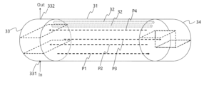
- FIG. 2 is a schematic diagram of the first kettle-type heat exchanger.
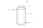
- FIG. 3 is a schematic diagram of the double pipe used in the comparative example.
- the present embodiment an embodiment of the present invention (hereinafter referred to as "the present embodiment") will be described in detail with reference to the drawings as necessary, but the present invention is not limited to this, and various modifications are possible without departing from the gist of the invention.
- positional relationships such as up, down, left, and right are based on the positional relationships shown in the drawings, unless otherwise specified.
- the dimensional ratios of the drawings are not limited to those shown in the drawings.
- the method for producing ethylene carbonate includes the steps of: a first reaction step of reacting ethylene oxide and carbon dioxide in a first reactor to obtain a reaction mixture containing ethylene carbonate; a first steam generating step of using a first kettle-type heat exchanger having the plurality of paths and a shell, introducing the reaction mixture into the paths and introducing water into the shell, thereby evaporating water by heat exchange; Including,
- the reaction temperature in the first reactor in the first reaction step is 150 to 200° C., and The difference between the reaction temperature in the first reaction step and the temperature of the steam generated from the shell in the first steam generation step is 5 to 20°C.
- the method for producing ethylene carbonate includes the steps of: a second reaction step in which the reaction mixture having undergone the first reaction step is reacted with ethylene oxide and carbon dioxide in a second reactor to obtain a reaction mixture containing ethylene carbonate; a second steam generation step in which a reaction mixture obtained by the second reaction step is introduced into the second kettle heat exchanger having the plurality of paths and a shell, and water is introduced into the shell to evaporate water by heat exchange; may also include
- the method may include a third reaction step in which the reaction mixture having undergone the second reaction step is reacted with ethylene oxide and carbon dioxide in a third reactor to obtain a reaction mixture containing ethylene carbonate.
- first,” “second,” and “third” do not refer to a sequence, but are used to distinguish between units, different devices, and different processes.
- Ethylene oxide used as a raw material in the method for producing ethylene carbonate according to this embodiment is a compound represented by formula (1).
- the raw material may contain bio-derived ethylene oxide and/or carbon dioxide by-produced in the production of bio-derived ethylene oxide.
- Ethylene carbonate which is the target compound in the production method of this embodiment, is a compound represented by formula (2).
- pass refers to the number of times that the tube-side fluid passes through the shell in a kettle heat exchanger.
- multiple passes means that the tube-side fluid in a kettle heat exchanger turns around two or more times.
- FIG. 1 shows a schematic configuration of the ethylene carbonate production method.
- the ethylene carbonate production method 1 according to this embodiment has a first reactor A, a first reaction liquid discharge line 2, a first kettle type heat exchanger 3, a second reactor B, a second reaction liquid discharge line 4, a second kettle type heat exchanger 5, a third reactor C, and a separation and recovery device E.
- Each step in the ethylene carbonate production method according to this embodiment will be described using production method 1.
- First reaction step In the first reaction step, ethylene oxide and carbon dioxide are reacted in a first reactor A to obtain a reaction mixture containing ethylene carbonate.
- the first reactor A a reactor using a commonly used reaction method, such as a completely mixed reactor or a plug flow reactor, may be used. Among these, it is preferable to use a completely mixed reactor as the first reactor A.
- the reactor for complete mixing it is preferable to use a reactor in which carbon dioxide is dissolved in the reaction liquid, Examples of the reactor include a shower nozzle type reactor, an ejector type reactor, and a bubble column reactor.
- a reactor for complete mixing it is also preferable to use a complete mixing tank reactor equipped with a Venturi stirrer.
- alkylene oxide and carbon dioxide are supplied from the top of the first reactor A.
- the reaction catalyst is adjusted to a predetermined concentration in advance using alkylene carbonate as a solvent, and is quantitatively supplied from the bottom of the first reactor A to the external circulation circuit 2 and is used in the first steam generation process.
- a catalyst may be used.
- the catalyst include organic catalysts such as tetraethylammonium bromide, halides of five-membered/six-membered ring hydrocarbons, rhodanium ammonium or its thermal decomposition products, inorganic catalysts such as bromides and iodides of metals or alkali metals, and catalysts to which a small amount of alcohol or water has been added.
- organic catalysts such as tetraethylammonium bromide, halides of five-membered/six-membered ring hydrocarbons, rhodanium ammonium or its thermal decomposition products
- inorganic catalysts such as bromides and iodides of metals or alkali metals
- catalysts to which a small amount of alcohol or water has been added are easy to recover.
- the amount of catalyst used is preferably 0.1 to 3 mass% of the total reaction system, and more preferably 0.1 to 2 mass%.
- the first reactor A is connected to a catalyst supply line Ac, and the catalyst is supplied into the first reactor A.
- the reaction temperature in the first reaction step is 150 to 200°C from the viewpoint of increasing the temperature of the steam recovered from the first kettle-type heat exchanger 3 described below and increasing its versatility as a heat source, and from the viewpoint of suppressing the production of high boiling point substances (HB) that cause fouling inside the device.
- the reaction temperature in the first reaction step is preferably 155 to 195°C, and more preferably 160 to 190°C.
- the reaction pressure in the first reaction step is preferably 2 to 15 MPaG, more preferably 4 to 12 MPaG, and even more preferably 6 to 10 MPaG.
- the reaction time in the first reaction step varies depending on the composition ratio of the raw materials ethylene oxide and carbon dioxide, the type and concentration of the catalyst used, the reaction temperature, etc.
- the average residence time calculated from the amount of retained liquid in the complete mixing reactor and the total amount of liquid supplied is preferably 0.5 to 10 hours, and more preferably 1 to 5 hours.
- the molar ratio of carbon dioxide to ethylene oxide in the first reaction step is preferably 1 to 5, and more preferably 1 to 2. It is preferable to supply carbon dioxide to the reactor by adjusting the amount of carbon dioxide supplied so that the pressure in the first reactor A is constant.
- First steam generation step In the first steam generation step, a first kettle-type heat exchanger having a plurality of paths and a shell is used, and the reaction mixture is introduced into the paths and water is introduced into the shell to evaporate water by heat exchange.
- the reaction liquid in the first reactor A is discharged from a first reaction liquid discharge line 2, and at least a part of it is sent to a first kettle-type heat exchanger 3.
- the steam generated from the first kettle-type heat exchanger 3 is taken out from a generated steam take-out line As.
- At least a part of the reaction liquid discharged to the first reaction liquid discharge line 2 is sent to a second reactor B through a reaction liquid supply line Ab.
- FIG. 2 is a schematic diagram of the first kettle-type heat exchanger.
- the first kettle-type heat exchanger 3 has a housing-shaped shell 31 and a number of tubes 32 (only some of which are shown) that penetrate the inside of the housing of the shell 31.
- the shell 31 has an inlet hole (not shown) for introducing water, and a steam outlet hole (not shown) for extracting steam generated by heat exchange.
- the tubes 32 penetrate the top and bottom surfaces of the shell 31, forming a flow path for the reaction liquid. Note that the flow paths within the tubes 32 are formed independently of the water in the shell 31 so that they do not mix with each other.
- Channel covers 33 and 34 are attached to the multiple tubes 32 that penetrate the shell 31, and form a flow path for the reaction liquid in combination with the tubes 32.
- the channel covers 33 and 34 partition the inside of the side adjacent to the shell 31, and form a reaction liquid flow path in the first kettle-type heat exchanger 3.
- the channel cover 33 has an inlet hole 331 for introducing the reaction liquid and an outlet hole 332 for discharging the reaction liquid.
- the reaction liquid flow path has four paths: a first path P1, a second path P2, a third path P3, and a fourth path P4.
- the material on the reaction liquid flow path side of the first kettle heat exchanger 3 is preferably corrosion-resistant to the reaction liquid, and specifically, is preferably stainless steel.
- the number of turns in the flow path of the reaction mixture in the first kettle-type heat exchanger is preferably 1 to 7, more preferably 2 to 6, and even more preferably 2 to 5, from the viewpoint of facilitating the maintenance and management of the heat exchanger.
- the temperature of the steam generated from the shell in the first steam generation process is preferably 145°C or higher, more preferably 150°C or higher, and even more preferably 150°C to 200°C, from the viewpoint of expanding the options for steam applications.
- the pressure of the steam generated from the shell in the first steam generation process is preferably 0.40 to 0.80 MPaG, and more preferably 0.50 to 0.70 MPaG, from the viewpoint of expanding the options for steam applications.
- the steam pressure is a value measured with a pressure gauge.
- the temperature of the water supplied into the shell of the first kettle-type heat exchanger 3 is preferably 140°C or higher, and more preferably 145 to 200°C.
- the difference between the temperature of the water supplied and the temperature of the steam generated from the shell is preferably 5 to 30°C, and more preferably 10 to 25°C.
- the temperature of the reaction liquid passing through the path of the first kettle-type heat exchanger 3 at the inlet of the first kettle-type heat exchanger 3 is preferably 150 to 200°C, more preferably 155 to 195°C, and even more preferably 160 to 190°C. By keeping the temperature within this range, it is possible to suppress the formation and adhesion of fouling substances on the inner wall of the first kettle-type heat exchanger on the reaction liquid flow path side.
- the method for producing ethylene carbonate according to this embodiment may include a first cleaning step of cleaning the inlet and outlet of the tube of the first kettle-type heat exchanger with a nozzle.
- the ethylene carbonate production method may include a first circulation step of circulating at least a part of the reaction liquid to the first reactor after the first steam generation step. As shown in Fig. 1, the first circulation step is carried out, for example, by supplying the reaction liquid to the first reactor A through a first reactor circulation line Ar.
- the ratio of "Ar(t/h)"/[Ap(t/h)] is preferably 50 to 150, more preferably 55 to 140, and even more preferably 60 to 130.
- the reaction liquid When using a complete mixing type reactor, it is preferable to circulate the reaction liquid at a high flow rate using a pump so that a larger amount of carbon dioxide is dissolved in the reaction mixture.
- the number of circulations per unit time is 10 to 70 times/hour, and preferably 20 to 50 times/hour.
- a first kettle-type heat exchanger is provided in the piping through which the reaction mixture is circulated by pumping to remove the heat of reaction, it is preferable to circulate at a high flow rate because this increases the cooling capacity of the heat exchanger.
- the method for producing ethylene carbonate according to this embodiment may include a second reaction step in which at least a part of the reaction mixture that has been subjected to the first reaction step is reacted with ethylene oxide and carbon dioxide in a second reactor B to obtain a reaction mixture containing ethylene carbonate.
- the reaction liquid in the second reactor B is discharged from a second reaction liquid discharge line 4, and at least a part of the reaction liquid is sent to a second kettle type heat exchanger 5.
- Steam generated from the second kettle type heat exchanger 5 is taken out from a generated steam take-out line Bs.
- At least a part of the reaction liquid discharged to the second reaction liquid discharge line 4 is sent to the third reactor C through a reaction liquid supply line Bb.
- the second reactor B is the same as the example of the first reactor A described above.
- alkylene oxide and carbon dioxide are supplied from the top of the second reactor B.
- the reaction catalyst is adjusted to a predetermined concentration in advance using alkylene carbonate as a solvent, and is quantitatively supplied from the bottom of the second reactor B to the external circulation circuit 4 and is used in the second steam generation process.
- the reaction temperature in the second reaction step is 150 to 200°C from the viewpoint of increasing the temperature of the steam recovered from the second kettle heat exchanger 5 described below and increasing its versatility as a heat source, and from the viewpoint of suppressing the production of high boiling point substances (hereinafter also referred to as "HB") that cause fouling inside the device.
- the reaction temperature in the second reaction step is preferably 155 to 195°C, and more preferably 160 to 190°C.
- the reaction pressure in the second reaction step is preferably 2 to 12 MPaG, more preferably 4 to 8 MPaG, and even more preferably 4.5 to 6.5 MPaG.
- the reaction time in the second reaction step varies depending on the composition ratio of the raw materials ethylene oxide and carbon dioxide, the type and concentration of the catalyst used, the reaction temperature, etc.
- the average residence time calculated from the amount of retained liquid in the complete mixing reactor and the total amount of liquid supplied is preferably 0.5 to 10 hours, and more preferably 1 to 5 hours.
- the molar ratio of carbon dioxide to ethylene oxide at the inlet of the second reactor in the second reaction step is preferably 1 to 5, and more preferably 1 to 4.
- the reaction liquid from the first reactor A may be used as is in the second reactor B without newly supplying carbon dioxide.
- the ethylene carbonate production method may also include a second steam generation step in which a second kettle heat exchanger having a plurality of paths and a shell is used, and the reaction mixture obtained in the second reaction step is introduced into the paths and water is introduced into the shell, thereby evaporating water by heat exchange.
- the configuration of the second kettle type heat exchanger is similar to that of the first kettle type heat exchanger described above.
- the number of passes in the second kettle heat exchanger is preferably 2 to 8, more preferably 2 to 7, and even more preferably 2 to 6, from the viewpoint of facilitating maintenance and management of the heat exchanger.
- the number of turns in the flow path of the reaction mixture in the second kettle-type heat exchanger is preferably 1 to 7, more preferably 1 to 6, and even more preferably 1 to 5, from the viewpoint of facilitating the maintenance and management of the heat exchanger.
- the difference between the reaction temperature in the second reaction process and the temperature of the steam generated from the shell in the second steam generation process is 5 to 20°C.
- the difference between the reaction temperature in the second reaction process and the temperature of the steam generated from the shell in the second steam generation process is preferably 5 to 15°C, and more preferably 6 to 15°C.
- the temperature of the steam generated from the shell in the second steam generation process is preferably 145°C or higher, and more preferably 150°C to 200°C, in order to broaden the options for steam applications.
- the pressure of the steam generated from the shell in the second steam generation process is preferably 0.40 to 0.80 MPaG, and more preferably 0.50 to 0.7 MPaG, from the viewpoint of expanding the options for steam applications.
- the steam pressure is a value measured with a pressure gauge.
- the temperature of the water supplied into the shell of the second kettle-type heat exchanger 5 is preferably 140°C or higher, and more preferably 145°C or higher.
- the difference between the temperature of the water supplied and the temperature of the steam generated from the shell is preferably 5 to 30°C, and more preferably 10 to 25°C.
- the temperature of the reaction liquid passing through the path of the second kettle-type heat exchanger 5 at the inlet of the second kettle-type heat exchanger 5 is preferably 150 to 200°C, more preferably 155 to 195°C, and even more preferably 160 to 190°C. By keeping the temperature within this range, it is possible to suppress the formation and adhesion of fouling substances on the inner wall of the second kettle-type heat exchanger on the reaction liquid flow path side.
- the method for producing ethylene carbonate according to this embodiment may include a second cleaning step of cleaning the inlets and outlets of the tubes of the second kettle heat exchanger with a nozzle.
- the ethylene carbonate production method may include a second circulation step of circulating at least a part of the reaction liquid to a second reactor after the second steam generation step. As shown in Fig. 1, the second circulation step is carried out, for example, by supplying the reaction liquid to a second reactor B through a second reactor circulation line Br.
- the ratio of "Br (t/h)"/[Ap (t/h)] is preferably 10 to 100, more preferably 15 to 95, and even more preferably 20 to 90.
- the reaction liquid When using a complete mixing reactor, it is preferable to circulate the reaction liquid at a high flow rate using a pump so that a larger amount of carbon dioxide is dissolved in the reaction mixture.
- the number of circulations per unit time is 5 to 50 times/hour, and preferably 10 to 30 times/hour.
- a second kettle-type heat exchanger is provided in the piping through which the reaction mixture is circulated by pumping to remove the heat of reaction, it is preferable to circulate at a high flow rate because this increases the cooling capacity of the heat exchanger.
- the method for producing ethylene carbonate according to this embodiment may include a third reaction step in which at least a part of the reaction mixture that has been subjected to the second reaction step is reacted with ethylene oxide and carbon dioxide in a third reactor C to obtain a reaction mixture containing ethylene carbonate.
- the third reactor is preferably a liquid-filled reactor.
- the third reactor is provided to react unreacted ethylene oxide with carbon dioxide.
- the third reactor preferably does not have an external circulation path.
- the method for producing ethylene carbonate according to this embodiment may include a separation and recovery step of separating and recovering ethylene carbonate from the reaction mixture that has been subjected to the first reaction step.
- the reaction mixture used in the separation and recovery step may be one that has further been subjected to the second reaction step or one that has further been subjected to the third reaction step.
- Dissolved carbon dioxide and alkylene oxide may be separated and removed from the reaction mixture prior to the separation and recovery step.
- Examples of the separation and recovery equipment E used for separation and recovery include a rectification tower, a distillation tower, a crystallizer, and a thin-film evaporator. Among these, a thin-film evaporator is preferred from the viewpoint of suppressing decomposition of the alkylene carbonate and the simplicity of the equipment.
- the steam used in the separation and recovery equipment E is led out through a steam drain line Eb.
- the steam obtained in the first steam generation process is used for the separation and recovery.
- the steam obtained in the second steam generation process is used for the separation and recovery.
- Japanese Patent Application Laid-Open No. 05-271218 describes a method for producing ethylene carbonate in which the reaction liquid that has not been subjected to the steam generation process is introduced into the jacket of the evaporator in the separation and recovery process. According to this method, the reaction heat of the ethylene carbonate production reaction is used as a heat source for the separation and recovery process without generating steam.
- the amount of steam generated from the kettle heat exchange in the first steam generation process is As (kg/h)
- the amount of steam generated from the kettle heat exchange in the first steam generation process is Bs (kg/h)
- the amount of steam used in the separation and recovery process is Eb (kg/h)
- the recovered steam usage rate in the steam usage rate Eb calculated by ⁇ [As (kg/h) + Bs (kg/h)] / Eb (kg/h) ⁇ ⁇ 100 is 40% or more.
- the recovered steam usage rate is preferably 50% or more, more preferably 60% or more, and even more preferably 65% or more. There is no particular upper limit to the recovered steam usage rate, but it may be, for example, 100% or less, or 90% or less.
- steam may be introduced from the outside through a steam supply line Si. Also, if excess steam is generated, the steam may be released to the outside through a steam release line So.
- the external steam consumption rate in the amount of steam consumed Eb calculated by ⁇ Si (kg/h)/Eb (kg/h) ⁇ ⁇ 100 is preferably 60% or less.
- the external steam consumption rate is preferably 50% or less, more preferably 40% or less, and even more preferably 35% or less.
- the "amount of steam supplied from outside” refers to the amount of steam newly generated by applying heat, not steam generated by utilizing recovered heat. More specifically, steam from outside is not steam generated in the first steam recovery process or the second steam recovery process, but steam newly generated by applying heat using a boiler or the like.
- part of the distillation residue is discharged from the waste liquid discharge line Acb, and part is recycled to the first reactor A.
- fresh catalyst may be supplied from the fresh catalyst supply line Acf.
- the ethylene carbonate production method according to this embodiment is preferably carried out on an industrial scale.
- industrial scale means a scale in which ethylene carbonate is produced at a rate of 1 ton/hour or more.
- the amount of ethylene carbonate produced in the ethylene carbonate production method according to this embodiment is preferably 1 ton/hour or more, more preferably 2 ton/hour or more, even more preferably 3 ton/hour or more, and even more preferably 4 to 20 ton/hour.
- the metal (potassium) concentration [mass %] of the catalyst was measured using an ICP emission spectrometer (ICP), and the catalyst amount [mass %] was calculated from the molecular weight of the catalyst (potassium iodide).
- Example 1 Ethylene carbonate was produced using the production apparatus shown in Figure 1.
- the first reactor A was a vertical cylindrical tank made of stainless steel.
- Ethylene oxide was cooled to about 5° C. and pressurized with a pump before being supplied.
- Carbon dioxide was prepared by gasifying liquefied carbon dioxide in a hot water bath type carbon dioxide evaporator, and adjusting the temperature to about 90° C. and the pressure to a constant level of about 9.81 MPaG before being supplied.
- the catalyst solution was supplied by mixing recovered catalyst recovered after refining ethylene carbonate products and fresh catalyst solution in a ratio of approximately 9:1.
- the kettle-type heat exchanger 3 connected to the first reactor A was a horizontal kettle-type heat exchanger.
- the kettle-type heat exchanger had four passes and three turns.
- the kettle-type heat exchanger 3 connected to the second reactor B was a horizontal kettle-type heat exchanger.
- the kettle-type heat exchanger had two passes and one turn.
- Table 1 shows the manufacturing conditions and the measurement results.
- Example 2 and 3 Ethylene carbonate was produced in the same manner as in Example 1 except for the production amount. Table 1 shows the manufacturing conditions and the measurement results.
- Examples 4 to 6 Comparative Examples 2 and 3
- Ethylene carbonate was produced in the same manner as in Example 1 except for the reaction temperature. In Comparative Example 2, no steam was recovered. Table 1 shows the manufacturing conditions and the measurement results.
- Example 7 and 8 Ethylene carbonate was produced in the same manner as in Example 1 except for the flow rate Ar of the circulation line of the first reactor. Table 1 shows the manufacturing conditions and the measurement results.
- Example 9 Ethylene carbonate was produced in the same manner as in Example 1 except for the feed water temperatures of the first and second kettle-type heat exchangers. Table 1 shows the manufacturing conditions and the measurement results.
- Ethylene carbonate was produced using the production apparatus shown in FIG. Ethylene carbonate was produced in the same manner as in Example 1, except that the kettle type heat exchangers in the reactors A and B were changed to multi-tube heat exchangers and steam recovery was not performed. Table 1 shows the manufacturing conditions and the measurement results.
- Example 9 there is no need to reduce the steam pressure for six months or more, but in Comparative Examples 2 to 6, the generated steam pressure must be reduced for one to four months, and heat recovery becomes impossible in the separation and recovery process.
- Example 9 an operation to reduce the steam pressure is required after six months of continuous operation.
- Comparative Example 1 uses a multi-tube heat exchanger, and therefore requires a larger amount of heat supplied from outside compared to Examples of the same scale.
- a First reactor Ac Catalyst supply line Ar First reactor circulation line As Generated vapor removal line Ab Reaction liquid supply line 2 First reaction liquid discharge line 3 First kettle type heat exchanger 31 Kettle type heat exchanger shell 32 Multiple tubes (only some are shown) penetrating the shell 31 33 Channel cover 34 Channel cover 331 Inlet hole 332 for introducing reaction liquid Outlet hole P1 for discharging reaction liquid First path P2 Second path P3 Third path P4 Fourth path B Second reactor Br Second reactor circulation line Bs Generated vapor extraction line Bb Reaction liquid supply line 4 Second reaction liquid discharge line 5 Second kettle type heat exchanger C Third reactor E Separation and recovery device Eb Steam drain line Acf Fresh catalyst supply line Acb Waste liquid discharge line So Steam release line Si Steam supply line
Landscapes
- Chemical & Material Sciences (AREA)
- Organic Chemistry (AREA)
- Organic Low-Molecular-Weight Compounds And Preparation Thereof (AREA)
Abstract
L'invention concerne un procédé de fabrication de carbonate d'éthylène qui comprend : une première étape de réaction pour obtenir un mélange réactionnel contenant du carbonate d'éthylène par réaction d'oxyde d'éthylène et de dioxyde de carbone à l'intérieur d'un premier réacteur ; et une première étape de génération de vapeur pour utiliser un premier échangeur de chaleur à calandre ayant une pluralité de chemins et une enveloppe pour effectuer un échange de chaleur et faire évaporer l'eau par introduction du mélange réactionnel dans les chemins et introduction d'eau dans l'enveloppe. La température de réaction dans le premier réacteur pendant la première étape de réaction est de 150 à 200°C, et la différence entre la température de réaction pendant la première étape de réaction et la température de vapeur générée par l'enveloppe pendant la première étape de génération de vapeur est de 5 à 20° C.
Priority Applications (1)
| Application Number | Priority Date | Filing Date | Title |
|---|---|---|---|
| JP2025507155A JP7782098B2 (ja) | 2023-03-16 | 2024-03-14 | エチレンカーボネートの製造方法 |
Applications Claiming Priority (2)
| Application Number | Priority Date | Filing Date | Title |
|---|---|---|---|
| JP2023-041979 | 2023-03-16 | ||
| JP2023041979 | 2023-03-16 |
Publications (1)
| Publication Number | Publication Date |
|---|---|
| WO2024190880A1 true WO2024190880A1 (fr) | 2024-09-19 |
Family
ID=92755861
Family Applications (1)
| Application Number | Title | Priority Date | Filing Date |
|---|---|---|---|
| PCT/JP2024/010056 Ceased WO2024190880A1 (fr) | 2023-03-16 | 2024-03-14 | Procédé de fabrication de carbonate d'éthylène |
Country Status (3)
| Country | Link |
|---|---|
| JP (1) | JP7782098B2 (fr) |
| TW (1) | TW202442641A (fr) |
| WO (1) | WO2024190880A1 (fr) |
Citations (5)
| Publication number | Priority date | Publication date | Assignee | Title |
|---|---|---|---|---|
| WO2004108696A1 (fr) * | 2003-06-04 | 2004-12-16 | Asahi Kasei Chemicals Corporation | Procede de fabrication de carbonate alkylene |
| WO2015182732A1 (fr) * | 2014-05-30 | 2015-12-03 | 丸善石油化学株式会社 | Appareil et procédé de production de carbonate cyclique |
| CN205046024U (zh) * | 2015-02-02 | 2016-02-24 | 中国石油天然气股份有限公司 | 环氧乙烷和二氧化碳合成碳酸乙烯酯的反应装置 |
| JP2022161807A (ja) * | 2021-04-08 | 2022-10-21 | 旭化成株式会社 | 環状アルキレンカーボネートの工業的製造方法 |
| JP2022551354A (ja) * | 2019-10-14 | 2022-12-09 | グリーン ケミカル カンパニー リミテッド | アルキレンカーボネート製造システム及びそれを利用した製造方法 |
Family Cites Families (1)
| Publication number | Priority date | Publication date | Assignee | Title |
|---|---|---|---|---|
| US7473349B2 (en) | 2004-12-30 | 2009-01-06 | Bp Corporation North America Inc. | Process for removal of sulfur from components for blending of transportation fuels |
-
2024
- 2024-03-14 WO PCT/JP2024/010056 patent/WO2024190880A1/fr not_active Ceased
- 2024-03-14 JP JP2025507155A patent/JP7782098B2/ja active Active
- 2024-03-15 TW TW113109763A patent/TW202442641A/zh unknown
Patent Citations (5)
| Publication number | Priority date | Publication date | Assignee | Title |
|---|---|---|---|---|
| WO2004108696A1 (fr) * | 2003-06-04 | 2004-12-16 | Asahi Kasei Chemicals Corporation | Procede de fabrication de carbonate alkylene |
| WO2015182732A1 (fr) * | 2014-05-30 | 2015-12-03 | 丸善石油化学株式会社 | Appareil et procédé de production de carbonate cyclique |
| CN205046024U (zh) * | 2015-02-02 | 2016-02-24 | 中国石油天然气股份有限公司 | 环氧乙烷和二氧化碳合成碳酸乙烯酯的反应装置 |
| JP2022551354A (ja) * | 2019-10-14 | 2022-12-09 | グリーン ケミカル カンパニー リミテッド | アルキレンカーボネート製造システム及びそれを利用した製造方法 |
| JP2022161807A (ja) * | 2021-04-08 | 2022-10-21 | 旭化成株式会社 | 環状アルキレンカーボネートの工業的製造方法 |
Also Published As
| Publication number | Publication date |
|---|---|
| JPWO2024190880A1 (fr) | 2024-09-19 |
| TW202442641A (zh) | 2024-11-01 |
| JP7782098B2 (ja) | 2025-12-08 |
Similar Documents
| Publication | Publication Date | Title |
|---|---|---|
| KR20220086665A (ko) | 기체-액체 기포층 반응기, 반응 시스템, 및 카보네이트 합성 방법 | |
| CN109134231B (zh) | 一种微分环流连续生产氯乙酸的装置与工艺 | |
| CN105026365B (zh) | 尿素合成方法和设备 | |
| US12012372B2 (en) | Process and plant for the synthesis of urea | |
| CN114573458A (zh) | 一种微通道反应器串联管式反应器合成四甲基碳酸氢铵的方法 | |
| JP7782098B2 (ja) | エチレンカーボネートの製造方法 | |
| KR101127162B1 (ko) | 반 연속식 공정을 이용한 불화에테르 제조방법 및 제조장치 | |
| EP2941416B1 (fr) | Procédé de transformation d´une installation de synthèse d'urée | |
| KR101385915B1 (ko) | 1,2-디클로르에탄의 제조 중에 발생한 반응열을 이용하기위한 방법 및 장치 | |
| JP4673028B2 (ja) | エチレンカーボネートの精製方法 | |
| US7199253B2 (en) | Method of manufacturing alkylene carbonate | |
| CN101657400B (zh) | 用于制备氯代醇的方法和设备 | |
| EP4452932B1 (fr) | Production d'urée par décapage thermique | |
| CN115974018B (zh) | 一种五氯化磷连续化合成工艺及装置 | |
| JP5114408B2 (ja) | 1,2−ジクロロエタンの精製のための蒸留塔の操作及び結合されたカセイソーダ蒸発濃縮の方法 | |
| CN213966566U (zh) | 一种反应釜、反应系统 | |
| JPH10512908A (ja) | マルチシアナートエステルの製造方法 | |
| JP7813576B2 (ja) | バイオ由来エチレンカーボネート及びその製造方法 | |
| CA3158794C (fr) | Reacteur a lit bouillonnant gaz-liquide, systeme de reaction et procede de synthese de carbonate | |
| CN212347756U (zh) | 一种甲基苯基碳酸酯反应精馏塔装置 | |
| WO2026059447A1 (fr) | Extraction thermique avec échange de chaleur hp-mp | |
| CN101228105B (zh) | 利用1,2-二氯乙烷制备过程中释放的反应热的方法和装置 | |
| RU2437869C2 (ru) | Способ и устройство для использования теплоты реакции, выделяющейся при получении 1,2-дихлорэтана | |
| MX2008003753A (en) | Method of operating a distillation column for purifying 1,2-dichloroethane and for coupled sodium hydroxide solution evaporative concentration |
Legal Events
| Date | Code | Title | Description |
|---|---|---|---|
| 121 | Ep: the epo has been informed by wipo that ep was designated in this application |
Ref document number: 24770983 Country of ref document: EP Kind code of ref document: A1 |
|
| WWE | Wipo information: entry into national phase |
Ref document number: 2025507155 Country of ref document: JP |
|
| NENP | Non-entry into the national phase |
Ref country code: DE |
|
| 122 | Ep: pct application non-entry in european phase |
Ref document number: 24770983 Country of ref document: EP Kind code of ref document: A1 |