WO2024190883A1 - 処理装置、載置部材及びプログラム - Google Patents
処理装置、載置部材及びプログラム Download PDFInfo
- Publication number
- WO2024190883A1 WO2024190883A1 PCT/JP2024/010085 JP2024010085W WO2024190883A1 WO 2024190883 A1 WO2024190883 A1 WO 2024190883A1 JP 2024010085 W JP2024010085 W JP 2024010085W WO 2024190883 A1 WO2024190883 A1 WO 2024190883A1
- Authority
- WO
- WIPO (PCT)
- Prior art keywords
- robot
- tip
- contact
- mounting member
- opposing
- Prior art date
- Legal status (The legal status is an assumption and is not a legal conclusion. Google has not performed a legal analysis and makes no representation as to the accuracy of the status listed.)
- Ceased
Links
Images


Classifications
-
- B—PERFORMING OPERATIONS; TRANSPORTING
- B25—HAND TOOLS; PORTABLE POWER-DRIVEN TOOLS; MANIPULATORS
- B25J—MANIPULATORS; CHAMBERS PROVIDED WITH MANIPULATION DEVICES
- B25J13/00—Controls for manipulators
- B25J13/08—Controls for manipulators by means of sensing devices, e.g. viewing or touching devices
-
- B—PERFORMING OPERATIONS; TRANSPORTING
- B25—HAND TOOLS; PORTABLE POWER-DRIVEN TOOLS; MANIPULATORS
- B25J—MANIPULATORS; CHAMBERS PROVIDED WITH MANIPULATION DEVICES
- B25J19/00—Accessories fitted to manipulators, e.g. for monitoring, for viewing; Safety devices combined with or specially adapted for use in connection with manipulators
-
- B—PERFORMING OPERATIONS; TRANSPORTING
- B25—HAND TOOLS; PORTABLE POWER-DRIVEN TOOLS; MANIPULATORS
- B25J—MANIPULATORS; CHAMBERS PROVIDED WITH MANIPULATION DEVICES
- B25J9/00—Program-controlled manipulators
- B25J9/10—Program-controlled manipulators characterised by positioning means for manipulator elements
Definitions
- This disclosure relates to technology for controlling the movement of robots.
- Patent document 1 describes technology related to a teaching method for a robot device.
- Patent document 2 describes technology related to robot calibration.
- the processing device includes an acquisition unit, a determination unit, and a lot control unit.
- At least one mounting member is arranged on a work object mounting surface of an unfixed work table for the robot.
- the acquisition unit acquires opposing member information when an opposing member of the robot is in contact with at least one mounting member.
- the determination unit determines the orientation of the mounting surface as viewed from above or the three-dimensional orientation of the mounting surface based on the opposing member information.
- the robot control unit controls the movement of the robot based on the orientation determined by the determination unit.
- the mounting member is a mounting member that is placed on the mounting surface of the robot for the work object.
- the mounting member has a groove portion into which the tip of the member placed on the robot fits.
- the inner surface of the groove portion has multiple surfaces that each come into point contact with the tip.
- the multiple surfaces of the mounting member have multiple opposing surfaces that face each other and a wall surface located at one end of the longitudinal direction of the groove.
- the multiple opposing surfaces include an inclined surface that slopes outwardly toward the top.
- the processing device includes a robot control unit that controls the robot so that the tip of the member moves within the groove of the mounting member.
- the robot control unit identifies the contact state of the tip with the inner surface of the groove based on the detection result of a sensor that detects the force applied to the tip.
- the robot control unit controls the robot so that the tip moves within the groove to the wall surface based on the identified contact state.
- the program causes a computer device to function as the processing device described above.
- FIG. 2 is a schematic diagram illustrating an example of a processing apparatus.
- FIG. 1 is a schematic diagram illustrating an example of a robot and an example of a state around the robot.
- FIG. 1 is a schematic diagram illustrating an example of a robot and an example of a state around the robot.
- FIG. 4 is a schematic diagram illustrating an example of an opposing member.
- FIG. 4 is a schematic diagram illustrating an example of a mounting member.
- FIG. 4 is a schematic diagram illustrating an example of a mounting member.
- FIG. 4 is a schematic diagram illustrating an example of a mounting member.
- 4A and 4B are schematic diagrams showing examples of arrangement of mounting members on a mounting surface.
- FIGS. 10A and 10B are schematic diagrams showing an example of a state in which an opposing member comes into contact with a mounting member.
- 10 is a schematic diagram showing an example of a state in which an opposing member comes into contact with an inner surface of a mounting member at one point.
- FIG. 10 is a schematic diagram showing an example of a state in which an opposing member comes into contact with an inner surface of a mounting member at two points.
- FIG. 10 is a schematic diagram showing an example of a state in which an opposing member comes into three-point contact with an inner surface of a mounting member.
- FIG. 10 is a flowchart showing an example of an operation of the processing device.
- 4 is a schematic diagram showing the relationship between a mounting member and a sensor coordinate system.
- FIGS. 10A to 10C are schematic diagrams showing an example of reference first contact position coordinates, reference second contact position coordinates, first contact position coordinates, and second contact position coordinates.
- 10 is a schematic diagram for explaining an example of a method for identifying the attitude of a mounting table.
- FIG. 10A and 10B are schematic diagrams showing examples of arrangement of two mounting members on a mounting surface.
- 11 is a schematic diagram showing an example of reference second contact position coordinates and second contact position coordinates of two mounting members.
- FIG. 10 is a schematic diagram for explaining an example of a method for identifying the attitude of a mounting table.
- FIG. FIG. 4 is a schematic diagram illustrating an example of a mounting member.
- FIG. 4 is a schematic diagram illustrating an example of a mounting member.
- FIG. 4 is a schematic diagram showing an example of a tip portion of an opposing member.
- FIG. FIG. 4 is a schematic diagram illustrating an example of a mounting member.
- 10 is a schematic diagram showing an example of a state in which a tip portion of an opposing member comes into contact with a recessed portion of a mounting member.
- FIG. FIG. 4 is a schematic diagram illustrating an example of a mounting member.
- 10 is a schematic diagram showing an example of a state in which a tip portion of an opposing member fits into a recessed portion of a mounting member.
- FIG. 10 is a schematic diagram for explaining an example of a method for identifying the attitude of a mounting table.
- FIG. 10 is a schematic diagram for explaining an example of a method for identifying the attitude of a mounting table.
- FIG. 10 is a schematic diagram for explaining an example of a method for identifying the attitude of a mounting table.
- FIG. 1 is a schematic diagram showing an example of the configuration of the processing device 1.
- the processing device 1 is capable of, for example, performing calibration to adjust the movement of the robot 10.
- the processing device 1 is also capable of, for example, controlling the robot 10.
- the processing device 1 can also be said to be a robot control device that controls the robot 10.
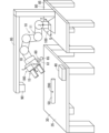
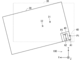
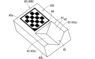
- FIG. 2 is a schematic diagram showing an example of the robot 10 and an example of the surroundings of the robot 10.
- the robot 10 performs work on, for example, an object 50 placed on the upper surface 35 of the work table 30.
- the robot 10 may hold the object 50 on the work table 30 and move it to another location, or may change the orientation of the held object 50 and place it back on the work table 30.
- the object 50 can also be said to be the work target 50 of the robot 10.
- the upper surface 35 of the work table 30 can also be said to be the placement surface 35 on which the work target 50 is placed.
- the position of the work target 50 (hereinafter also simply referred to as the object 50) on the placement surface 35 may be fixed, for example, by a fixing jig.
- multiple objects 50 may be placed on the placement surface 35.
- the object 50 may not be placed directly on the placement surface 35, but may be placed on the placement surface 35 via a container, for example. In other words, the object 50 may be placed in a container on the placement surface 35.
- the shape of the placement surface 35 is, for example, rectangular.
- the robot 10 includes, for example, an arm 11 and an end effector 15 connected to the arm 11.
- the end effector 15 is capable of holding an object 50.
- the arm 11 includes, for example, multiple joints.
- the posture of the arm 11 changes as the amount of rotation of at least one of the multiple joints changes.
- the change in posture of the arm 11 changes the position and posture of the end effector 15.
- the change in posture of the arm 11 also changes the position and posture of the object 50 held by the end effector 15.
- the end effector 15 is capable of, for example, grasping and holding the object 50 with multiple fingers.
- the end effector 15 may hold the object 50 by suction.
- the robot 10 may, for example, hold the object 50 with the end effector 15 and move the arm 11 (in other words, change the posture of the arm 11) to move the held object 50 to another location.
- the robot 10 may also move the arm 11 (in other words, change the posture of the arm 11) to change the posture of the object 50 held by the end effector 15 (for example, flip the object 50 over), and then place it again on the placement surface 35.
- the robot 10 is equipped with, for example, a force sensor 18.
- the force sensor 18 is provided, for example, on the wrist portion of the end effector 15.
- the force sensor 18 is capable of repeatedly detecting, for example, the force acting on the end effector 15.
- the force sensor 18 may be, for example, a six-axis force sensor.
- the force sensor 18 may be, for example, an electrical resistance type, an electrostatic capacitance type, a piezoelectric type, or an optical type.
- the robot 10 is fixed, for example, to the upper surface 85 of the stand 80.
- the robot 10 may be movable or transportable by the user during work.
- the stand 80 may have a moving mechanism, such as casters, and the robot 10 may be movable or transportable together with the stand 80 during work.
- One end of a holding arm 95 that holds a camera 90 is attached to the upper surface 85 of the stand 80.
- the camera 90 is fixed to the other end of the holding arm 95.
- the camera 90 is capable of photographing the placement surface 35 of the workbench 30.
- the relative positional relationship between the camera 90 and the robot 10 is fixed.
- Camera 90 is, for example, a three-dimensional camera. Camera 90 captures an image of the shooting range including the support surface 35 of workbench 30, and generates, for example, a two-dimensional color image and a distance image. Each pixel value of the color image includes, for example, an R component (red component), a G component (green component), and a B component (blue component). Such a color image is also called an RGB image. The color image shows the state of the shooting range.
- the distance image is an image that represents, in two dimensions, the distance to each measurement point included in the shooting range. Each pixel value of the distance image indicates the distance to the measurement point corresponding to that pixel value.
- the distance image is also called a depth image.
- the camera 90 that photographs the workbench 30 may be held by a holding arm 96 extending from the workbench 30.
- One end of the holding arm 96 is attached to the workbench 30, and the camera 90 is fixed to the other end of the holding arm 96.
- a working point 200 of the robot 10 is set based on the mounting surface 35 of the worktable 30.
- the working point 200 means the position of a specific part of the robot 10 when the robot 10 performs work.
- the working point 200 can also be called the work position 200.
- the processing device 1 controls the movement of the robot 10, moves the specific part of the robot 10 to the working point 200, and causes the robot 10 to perform work.
- the robot 10 moves according to the working point 200.
- the working point 200 is the position of the end effector 15 when holding the object 50.
- the working point 200 may be set, for example, on the surface of the object 50 on the placement surface 35, or may be set near the object 50.
- the processing device 1 moves the end effector 15 to the working point 200 and causes the end effector 15 to hold the object 50.
- the robot 10 is equipped with a camera for photographing the mounting surface 35 of the worktable 30.
- This camera is fixed to the end effector 15, for example.
- the position of the camera when the robot 10 is performing the task of photographing the mounting surface 35 with the camera becomes the working point 200.
- the working point 200 is set, for example, at a location a predetermined distance above the center of the mounting surface 35.
- the processing device 1 moves the camera of the robot 10 to the working point 200 and causes the camera of the robot 10 to photograph the mounting surface 35.
- multiple work points 200 are set relative to the placement surface 35, corresponding to each of the multiple objects 50. Even if the position and orientation of the placement surface 35 change, the relative position of the work point 200 with respect to the placement surface 35 remains constant. When a specific part of the robot 10 moves to the work point 200 and the robot 10 performs a task, this can be said to be a movement of the robot 10 relative to the placement surface 35. When at least one of the position and orientation of the placement surface 35 changes, causing the work point 200 to change, the movement of the robot 10 relative to the placement surface 35 changes. The robot 10 performs a movement according to the work point 200.
- the processing device 1 stores position information of the working point 200 in the robot coordinate system 100 when the position and orientation of the mounting surface 35 of the worktable 30 are set to a predetermined position and orientation in the robot coordinate system 100 of the robot 10.
- the position information of the working point 200 in the robot coordinate system 100 is expressed, for example, by the position coordinates of the working point 200 in the robot coordinate system.
- the robot coordinate system 100 is an XYZ Cartesian coordinate system set in the robot 10 as shown in FIG. 2.
- the origin of the robot coordinate system 100 is set, for example, at the end of the arm 11 of the robot 10 on the side of the base 80.
- the XY plane of the robot coordinate system 100 is set parallel to the top surface 85 of the base 80, and the Z axis of the robot coordinate system 100 is set in a direction perpendicular to the top surface 85.
- the X axis of the robot coordinate system 100 is set, for example, parallel to the short side direction of the rectangular top surface 85.
- the Y axis of the robot coordinate system 100 is set, for example, parallel to the long side direction of the top surface 85.
- the Z axis of the robot coordinate system 100 is, for example, approximately parallel to the direction of gravity.
- the processing device 1 grasps the position and posture of the robot 10 in the robot coordinate system 100, and controls the movement of the robot 10 in the robot coordinate system 100.
- the position and posture of an object such as a worktable may be collectively referred to as the position and posture.
- the above-mentioned predetermined position and posture with respect to the placement surface 35 may be referred to as the reference position and posture.
- the above-mentioned predetermined position with respect to the placement surface 35 may be referred to as the reference position, and the above-mentioned predetermined posture with respect to the placement surface 35 may be referred to as the reference posture.
- the position information of the working point 200 in the robot coordinate system 100 when the position and posture of the placement surface 35 in the robot coordinate system 100 is set to the reference position and posture in the robot coordinate system 100 may be referred to as the reference working point position information.
- the longitudinal direction and lateral direction of the placement surface 35 are parallel to the X-axis and Y-axis of the robot coordinate system 100, respectively, and the direction perpendicular to the placement surface 35 is parallel to the Z-axis of the robot coordinate system 100.
- Figure 2 shows an example of the position and posture of the placement surface 35 being the reference position and posture.
- the processing device 1 can move a specific part of the robot 10 (e.g., the end effector 15) to the working point 200 based on the reference working point position information. Therefore, when the position and posture of the mounting surface 35 is the reference position and posture, the robot 10 can properly perform work at the working point 200.
- a specific part of the robot 10 e.g., the end effector 15
- the processing device 1 attempts to move a specified part of the robot 10 to the working point 200, the actual destination will be a position shifted from the working point 200 by the amount that the position and orientation of the placement surface 35 deviates from the reference position and orientation.
- position information and position coordinates means position information and position coordinates in the robot coordinate system 100.
- the placement surface 35 may be referred to as the target placement surface 35.
- the work table 30 equipped with the target placement surface 35 may be referred to as the target work table 30.
- the placement member 40 on the target placement surface 35 may be referred to as the target placement member 40.
- the processing device 1 can correct the reference work point position information and obtain the position information of the work point 200 based on the target placement surface 35.
- a mounting member 40 arranged on the mounting surface 35 and an opposing member 60 arranged on the robot 10 are used.
- the opposing member 60 is positioned so as to face the mounting surface 35.
- Each of the mounting member 40 and the opposing member 60 can also be considered a calibration member.
- the opposing member 60 is attached to, for example, the end effector 15.
- the opposing member 60 may be removably fixed to, for example, the housing of the end effector 15.
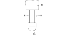
- the opposing member 60 is, for example, a rod-shaped member.
- the tip of the opposing member 60 is rounded.
- the opposing member 60 includes, for example, a rod-shaped portion 61 and a tip portion 65 connected to one end of the rod-shaped portion 61.
- the tip portion 65 is, for example, spherical.
- the other end of the rod-shaped portion 61 is attached to the end effector 15.
- the tip portion 65 of the opposing member 60 comes into contact with the mounting member 40.
- the position and orientation of the tip portion 65 of the opposing member 60 relative to the robot 10 or the end effector 15 are fixed.
- the tip 65 of the opposing member 60 may be, for example, hemispherical, as shown in FIG. 4.
- the end effector 15 may have a recess into which the opposing member 60 is inserted.
- the recess may be, for example, a screw hole, and the other end of the opposing member 60 (i.e., the end opposite the tip 65) may be, for example, a screw, so that the opposing member 60 can be fixed to the end effector 15.
- the other end of the opposing member 60 may have an indication line indicating a predetermined insertion depth so that the relative position and posture of the tip 65 of the opposing member 60 and the robot 10 or the end effector 15 are constant.
- the mounting member 40 is, for example, fixedly positioned with respect to the mounting surface 35.
- the position and orientation of the mounting member 40 relative to the mounting surface 35 is fixed. Even if at least one of the position and orientation of the mounting surface 35 changes, the position of the work point 200 relative to the mounting member 40 with respect to the mounting surface 35 as a reference is constant. It can also be said that the position of the work point 200 relative to the mounting member 40 is constant even if at least one of the position and orientation of the mounting member 40 changes.
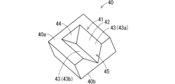
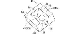
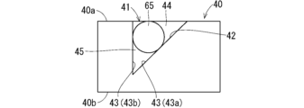
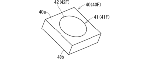
- FIG. 5 is a schematic perspective view showing an example of the mounting member 40.
- FIG. 6 is a schematic plan view showing an example of the mounting member 40.
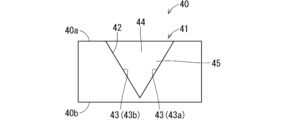
- FIG. 7 is a schematic side view showing an example of the mounting member 40.
- the mounting member 40 has a recess 41 into which the tip 65 of the opposing member 60 arranged on the robot 10 fits.
- the recess 41 opens toward the upper surface 40a of the mounting member 40, for example.
- the bottom surface 40b of the mounting member 40 is flat, for example.
- the recess 41 is, for example, a groove portion.
- the recess 41 is a V-groove portion.
- the recess 41 that is a groove portion may be referred to as the groove portion 41.
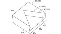
- each opposing surface 43 is, for example, an inclined surface that slopes outwardly toward the upper side.
- each opposing surface 43 is, for example, an inclined surface that slopes outwardly in a direction perpendicular to the mounting surface 35.
- each opposing surface 43 is an inclined surface that slopes outwardly in a direction perpendicular to the depth direction of the groove portion 41.
- the wall surface 44 is, for example, parallel to the direction perpendicular to the mounting surface 35.
- the opposing surface 43 shown on the right side of Fig. 7 may be referred to as the first opposing surface 43a, and the opposing surface 43 shown on the left side of Fig. 7 may be referred to as the second opposing surface 43b.
- the direction from the opening 45 along the groove 41 toward the wall surface 44 may be referred to as the depth direction of the mounting member 40
- the direction from the wall surface 44 toward the opening 45 along the groove 41 (the front direction of the paper in Fig. 7) may be referred to as the front direction of the mounting member 40.
- the direction from the bottom surface 40b toward the top surface 40a along the depth direction of the groove 41 may be referred to as the upward direction of the mounting member 40
- the direction from the top surface 40a toward the bottom surface 40b along the depth direction of the groove 41 may be referred to as the downward direction of the mounting member 40
- the direction from the first opposing surface 43a to the second opposing surface 43b along the direction perpendicular to the depth and longitudinal directions of the groove 41 (left direction in FIG. 7) may be referred to as the left direction of the mounting member 40.
- the direction from the second opposing surface 43b to the first opposing surface 43a along the direction perpendicular to the depth and longitudinal directions of the groove 41 (right direction in FIG. 7) may be referred to as the right direction of the mounting member 40.
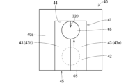
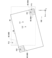
- FIG. 8 is a schematic diagram showing an example of the placement of the mounting member 40 on the mounting surface 35.
- FIG. 8 shows the mounting surface 35 in the reference position and orientation.
- the mounting member 40 is placed at the end of the mounting surface 35.
- the mounting member 40 is placed at a corner of the mounting surface 35.
- the mounting member 40 is less likely to interfere with the work of the robot 10.
- the mounting member 40 is placed at a corner of the mounting surface 35 as in the example of FIG. 8, the mounting member 40 is even less likely to interfere with the work of the robot 10.
- the position and orientation of the mounting member 40 on the mounting surface 35 are not limited to the example of FIG. 8.
- the mounting member 40 may have a linear or right-angled step on its bottom surface, and the step may be arranged to engage with the edge or corner of the workbench 30.
- Figure 8 shows the relationship between the mounting surface 35 in the reference position and posture on which the mounting member 40 is placed and the robot coordinate system 100.
- the Z axis of the robot coordinate system 100 is, for example, parallel to the depth direction of the groove portion 41 of the mounting member 40 on the mounting surface 35 in the reference position and posture.
- the Z axis of the robot coordinate system 100 is, for example, parallel to the up-down direction of the mounting member 40 on the mounting surface 35 in the reference position and posture.
- the positive direction of the Z axis of the robot coordinate system 100 is set, for example, in the same direction as the upward direction of the mounting member 40 on the mounting surface 35 in the reference position and posture.
- the Y axis of the robot coordinate system 100 is, for example, parallel to the longitudinal direction (in other words, the extension direction) of the groove portion 41 of the mounting member 40 on the mounting surface 35 in the reference position and posture.
- the positive direction of the Y axis of the robot coordinate system 100 is set, for example, in the same direction as the depth direction of the mounting member 40 on the mounting surface 35 in the reference position and posture.
- the X-axis of the robot coordinate system 100 is, for example, parallel to a direction perpendicular to the depth direction and longitudinal direction of the groove portion 41 of the mounting member 40 on the mounting surface 35 in the reference position and posture (the left-right direction in FIG. 8).
- the X-axis of the robot coordinate system 100 is, for example, parallel to the left-right direction of the mounting member 40 on the mounting surface 35 in the reference position and posture.
- the positive direction of the X-axis of the robot coordinate system 100 is set, for example, in the same direction as the left direction of the mounting member 40 on the mounting surface 35 in the reference position and posture.
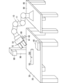
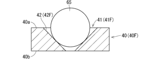
- FIG. 9 is a schematic diagram showing an example of the state in which the tip 65 comes into contact with the inner surface 42 of the groove portion 41.
- the tip 65 makes point contact with each of the pair of opposing surfaces 43 of the groove portion 41.
- the tip 65 also makes point contact with the wall surface 44 of the groove portion 41. It can be said that the mounting member 40 has multiple surfaces, each of which makes point contact with the tip 65.
- the posture of the mounting surface 35 of the workbench 30 is determined based on the opposing member information regarding the opposing member 60 acquired when the opposing member 60 is in contact with the mounting member 40.
- the opposing member information acquired when the opposing member 60 is in contact with the mounting member 40 may be referred to as contact opposing member information.
- the contact opposing member information includes, for example, position information of the tip 65 when the tip 65 is in contact with a predetermined location on the inner surface 42 of the groove 41.
- the contact opposing member information includes position information of the tip 65 at a predetermined contact position of the tip 65 on the inner surface 42 of the groove 41.
- this position information may be referred to as contact position information.
- the contact position information is expressed, for example, in position coordinates in the robot coordinate system.
- the movement of the robot 10 relative to the mounting surface 35 is adjusted based on the identified posture of the mounting surface 35 (also referred to as the specific posture of the mounting surface 35) and the contact position information included in the contact opposing member information. This allows the movement of the robot 10 relative to the mounting surface 35 to be appropriately adjusted. For example, based on the specific posture of the mounting surface 35 and the contact position information, the reference working point position information is corrected to determine the current position information of the working point 200. Calibration will be explained in detail later.
- the processing device 1 includes, for example, a control unit 2, a storage unit 3, an interface 4, and an interface 5.
- the processing device 1 may also be referred to as, for example, a processing circuit.
- the interface 4 is capable of communicating with the camera 90.
- the control unit 2 can acquire images generated by the camera 90 through the interface 4.
- the interface 4 can also be called, for example, an interface circuit, a communication unit, or a communication circuit.
- the interface 4 may communicate with the camera 90 via wired communication or wireless communication.
- the interface 5 is capable of communicating with the robot 10.
- the control unit 2 is capable of controlling the robot 10 through the interface 5.
- the interface 5 can be, for example, an interface circuit, a communication unit, or a communication circuit.
- the interface 5 may communicate with the robot 10 via wired communication or wireless communication.
- the control unit 2 is capable of overall management of the operation of the processing device 1 by controlling the other components of the processing device 1.
- the control unit 2 can be, for example, a control circuit.
- the control unit 2 includes at least one processor to provide control and processing power to perform various functions, as described in more detail below.
- the at least one processor may be implemented as a single integrated circuit (IC) or as multiple communicatively connected integrated circuits ICs and/or discrete circuits.
- the at least one processor may be implemented according to various known techniques.
- a processor includes one or more circuits or units configured to perform one or more data computation procedures or processes, e.g., by executing instructions stored in associated memory.
- a processor may be firmware (e.g., discrete logic components) configured to perform one or more data computation procedures or processes.
- the processor may include one or more processors, controllers, microprocessors, microcontrollers, application specific integrated circuits (ASICs), digital signal processors, programmable logic devices, field programmable gate arrays, or any combination of these devices or configurations, or other known devices and configurations, to perform the functions described below.
- ASICs application specific integrated circuits
- digital signal processors programmable logic devices, field programmable gate arrays, or any combination of these devices or configurations, or other known devices and configurations, to perform the functions described below.
- the control unit 2 may, for example, include a CPU (Central Processing Unit) as a processor.
- the memory unit 3 may include a non-transitory recording medium readable by the CPU of the control unit 2, such as a ROM (Read Only Memory) and a RAM (Random Access Memory).
- the memory unit 3 stores, for example, a program 3a for controlling the processing device 1.
- the various functions of the control unit 2 are realized, for example, by the CPU of the control unit 2 executing the program 3a in the memory unit 3.
- the memory unit 3 stores reference working point position information.
- control unit 2 may include multiple CPUs.
- the control unit 2 may also include at least one DSP (Digital Signal Processor). All or some of the functions of the control unit 2 may be realized by a hardware circuit that does not require software to realize the function.
- the memory unit 3 may also include a non-transitory computer-readable recording medium other than ROM and RAM.
- the memory unit 3 may include, for example, a small hard disk drive and an SSD (Solid State Drive).
- the control unit 2 performs calibration to adjust the movement of the robot 10 based on the placement surface 35.
- the control unit 2 for example, acquires contact opposing member information, and identifies the posture of the placement surface 35 of the worktable 30 based on the acquired contact opposing member information. Then, the control unit 2 corrects the reference work point position information based on the identified posture of the placement surface 35 and the contact position information included in the contact opposing member information, and obtains the current position information of the work point 200.
- the control unit 2 includes, for example, a robot control unit 20 that controls the robot 10, an identification unit 25, and an acquisition unit 27.
- the robot control unit 20, the identification unit 25, and the acquisition unit 27 are functional blocks formed in the control unit 2, for example, when the CPU of the control unit 2 executes a program 3a in the storage unit 3. Note that all or some of the functions of the robot control unit 20 may be realized by a hardware circuit that does not require software to realize the function. The same applies to the identification unit 25 and the acquisition unit 27.
- the acquisition unit 27 can acquire the contact opposing member information.
- the identification unit 25 identifies the posture of the target placement surface 35 based on the contact opposing member information acquired by the acquisition unit 27.
- the identification unit 25 identifies, for example, the three-dimensional posture (referred to as the three-dimensional posture) of the target placement surface 35 based on the contact opposing member information.
- the robot control unit 20 adjusts the movement of the robot 10 based on the target placement surface 35 as a reference, based on the posture (e.g., the three-dimensional posture) of the target placement surface 35 identified by the identification unit 25 and the contact position information included in the contact opposing member information.
- the robot control unit 20 corrects the reference working point position information based on, for example, the posture of the target placement surface 35 identified by the identification unit 25 and the contact position information included in the contact opposing member information, to obtain current position information of the working point 200.
- the robot control unit 20 controls the robot 10 through the interface 5.
- the robot control unit 20 also determines the contact state of the tip 65 of the opposing member 60 with the inner surface 42 of the groove 41 of the mounting member 40.
- the force sensor 18 also simply called the sensor 18 provided in the robot 10 detects the force acting on the tip 65 during calibration.
- the robot control unit 20 determines the contact state of the tip 65 with the inner surface 42 of the groove 41 based on the detection result of the sensor 18.
- the sensor 18 outputs force detection information indicating the detection result.
- the robot control unit 20 acquires the force detection information output from the sensor 18 through the interface 5.
- the robot control unit 20 determines the contact state of the tip 65 with the inner surface 42 of the groove 41 based on the acquired force detection information.
- the robot control unit 20 controls the movement of the robot 10 so that the tip 65 of the opposing member 60 moves within the groove 41 based on the determination result of the contact state of the tip 65 with the inner surface 42 of the groove 41.
- the operator instructs the processing device 1 to perform calibration.
- the processing device 1 has an input unit that accepts instructions input by the operator, the operator may instruct the processing device 1 to perform calibration through the input unit.
- the input unit provided in the processing device 1 may include, for example, a mouse, a keyboard, a touch sensor, etc.
- the operator may also instruct the processing device 1 to perform calibration using an information processing terminal that can communicate with the processing device 1 via a network.
- the information processing terminal may be, for example, a notebook or desktop personal computer, or a tablet terminal.
- the processing device 1 When the processing device 1 receives an instruction to perform calibration, it starts calibrating the robot 10. During the calibration, the robot control unit 20 of the processing device 1 determines whether the tip 65 is in contact with only the first opposing surface 43a based on the force detection information output from the sensor 18. When the tip 65 is not in contact with the first opposing surface 43a, the robot control unit 20 controls the movement of the robot 10 so that the tip 65 moves downward (toward the ground or floor) so that the tip 65 is in contact with only the first opposing surface 43a.
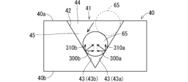
- FIG. 10 is a schematic diagram showing an example of how the tip 65 moves downward and contacts only the first opposing surface 43a of the groove 41. When the tip 65 contacts only the first opposing surface 43a of the groove 41, the tip 65 comes into contact with the inner surface 42 of the groove 41 at one point.
- the tip 65 when the tip 65 contacts only the first opposing surface 43a, the tip 65 receives a force 310a directed upward from the mounting member 40 and a force 300a directed leftward from the mounting member 40.
- the tip 65 when the tip 65 contacts only the first opposing surface 43a of the groove portion 41, the tip 65 receives a force 310a directed upward from the mounting member 40 and a force 300a directed leftward from the mounting member 40.
- the force 300a may be referred to as the leftward force 300a
- the force 310a may be referred to as the upward force 310a.
- the robot control unit 20 controls the robot 10 based on the force detection information so that the tip 65 moves along the first opposing surface 43a toward the bottom of the inner surface 42 of the groove 41.
- the robot control unit 20 determines that the tip 65 has reached the bottom of the inner surface 42 of the groove 41 and is in contact only with the first opposing surface 43a and the second opposing surface 43b.
- Figure 11 is a schematic diagram showing an example of the tip 65 in contact only with the first opposing surface 43a and the second opposing surface 43b.
- the determination unit 25 of the processing device 1 stores the current position information of the tip 65, that is, the position information of the tip 65 at the first contact position on the inner surface 42 of the groove portion 41, as first contact position information.
- the tip 65 in contact only with the first opposing surface 43a and the second opposing surface 43b makes two-point contact with the inner surface 42 of the groove portion 41.
- the first contact position can also be said to be, for example, the two-point contact position of the tip 65 on the inner surface 42.
- the first contact position is located on the inner surface 42.
- the processing device 1 determines that the tip 65 is in contact only with the first opposing surface 43a and the second opposing surface 43b based on the force detection information.
- the tip 65 when the tip 65 contacts only the first opposing surface 43a and the second opposing surface 43b, the tip 65 receives an upward force 300a and a leftward force 310a from the first opposing surface 43a, and receives a force 310b (also referred to as upward force 310b) directed toward the upper side of the target mounting member 40 and a force 300b (also referred to as rightward force 300b) directed toward the right side of the target mounting member 40 from the second opposing surface 43b.
- the tip 65 contacts only the first opposing surface 43a and the second opposing surface 43b, it receives the upward force 300a and the leftward force 310a, and the upward force 310b and the rightward force 300b.
- the force acting on the tip 65 in the left-right direction of the target placement member 40 is smaller than when the tip 65 contacts only the first opposing surface 43a.
- the upward forces 310a and 310b increase the force acting on the tip 65 in the up-down direction of the target placement member 40.
- the robot control unit 20 controls the robot 10 based on the force detection information so that the tip 65 moves along the groove 41 toward the wall surface 44.
- the robot control unit 20 determines that the tip 65 reaches the wall surface 44 of the groove 41 and the tip 6 is in contact with only the first opposing surface 43a, the second opposing surface 43b, and the wall surface 44.
- Figure 12 is a schematic diagram showing an example of the tip 6 in contact with only the first opposing surface 43a, the second opposing surface 43b, and the wall surface 44.
- the determination unit 25 stores the current position information of the tip 65, that is, the position information of the tip 65 at the second contact position of the inner surface 42 of the groove portion 41, as second contact position information.
- the tip 65 in contact only with the first opposing surface 43a, the second opposing surface 43b, and the wall surface 44 is in three-point contact with the inner surface 42 of the groove portion 41.
- the second contact position can be said to be, for example, the three-point contact position of the tip 65 on the inner surface 42.
- the second contact position is located away from the first contact position along the placement surface 35.
- the second contact position is located away from the first contact position along the longitudinal direction of the groove portion 41 on the inner surface 42 of the groove portion 41.
- the second contact position can also be said to be the contact position of the opposing member 60 with the wall surface 44.
- the processing device 1 determines that the tip 65 is in contact only with the first opposing surface 43a, the second opposing surface 43b, and the wall surface 44.
- the tip 65 when the tip 65 is in contact only with the first opposing surface 43a, the second opposing surface 43b, and the wall surface 44, the tip 65 receives an upward force 300a and a leftward force 310a from the first opposing surface 43a, and receives an upward force 300b and a rightward force 310b from the second opposing surface 43b.
- the tip 65 also receives a force 320 (also called a forward force 320) directed toward the front of the target placement member 40 from the wall surface 44.
- the tip 65 When the tip 65 is in contact only with the first opposing surface 43a, the second opposing surface 43b, and the wall surface 44, the tip 65 receives the upward force 300a and the leftward force 310a, the upward force 300b and the rightward force 310b, and the forward force 320.
- the identification unit 25 of the processing device 1 identifies the posture of the target placement surface 35 based on the first contact position information and the second contact position information.
- the first contact position information and the second contact position information can be said to be information about the opposing member 60 acquired when the opposing member 60 is in contact with the target placement member 40, that is, contact opposing member information.
- the robot control unit 20 corrects the reference work point position information based on the specific posture of the target placement surface 35 and the second contact position information to obtain current position information of the work point 200.
- the robot control unit 20 can appropriately move a specific part of the robot 10 (e.g., the end effector 15) to the work point 200 based on the position information obtained for the work point 200, and cause the robot 10 to perform work at the work point 200. It can be said that the robot control unit 20 controls the movement of the robot 10 based on the specific posture of the target placement surface 35 and the second contact position information.
- a specific part of the robot 10 e.g., the end effector 15
- an xyz orthogonal coordinate system 180 is set in the sensor 18.
- the xyz orthogonal coordinate system 180 set in the sensor 18 is referred to as the sensor coordinate system 180.
- the x-axis, y-axis, and z-axis of the sensor coordinate system 180 are referred to as the sensor x-axis, the sensor y-axis, and the sensor z-axis, respectively.
- the x-axis, y-axis, and z-axis of the sensor coordinate system 180 are referred to as the sensor x-direction, the sensor y-direction, and the sensor z-direction, respectively.
- the positive and negative directions of the sensor x-axis are referred to as the sensor +x-direction and the sensor -x-direction, respectively.
- the positive and negative directions of the sensor y-axis are referred to as the sensor +y-direction and the sensor -y-direction, respectively.
- the positive and negative directions of the sensor z-axis are referred to as the sensor +z-direction and the sensor -z-direction, respectively.
- the sensor 18 detects a force in the sensor x direction acting on the tip 65 of the opposing member 60, a force in the sensor y direction acting on the tip 65, and a force in the sensor z direction acting on the tip 65.
- the force in the sensor x direction detected by the sensor 18 will be referred to as the sensor x direction detection force.
- the force in the sensor y direction detected by the sensor 18 will be referred to as the sensor y direction detection force.
- the force in the sensor z direction detected by the sensor 18 will be referred to as the sensor z direction detection force.
- the force detection information output from the sensor 18 includes the sensor x-direction detection force, the sensor y-direction detection force, and the sensor z-direction detection force.
- the effect of gravity is cancelled out in the force detection information output from the sensor 18. Therefore, when an object is not in contact with the end effector 15 and the opposing member 60, the sensor x-direction detection force, the sensor y-direction detection force, and the sensor z-direction detection force included in the force detection information are each zero.
- the sensor z direction is set along the longitudinal direction of the opposing member 60 (in other words, the longitudinal direction of the rod-shaped portion 61).
- the sensor +z direction is set in the same direction as the direction from the base side of the opposing member 60 (in other words, the end effector 15 side) toward the tip portion 65.
- FIG. 13 is a flow chart showing an example of calibration.
- the processing device 1 receives an instruction to perform calibration, and the robot control unit 20 changes the posture of the arm 11 so that the orientation of the sensor +z direction is the same as the positive direction of the Z axis of the robot coordinate system 100.
- the sensor -z direction is roughly the same as the direction of gravity.
- the sensor z axis is parallel to the Z axis of the robot coordinate system 100.
- the direction perpendicular to the target placement surface 35 does not change significantly from the direction perpendicular to the placement surface 35 in the reference position and posture.
- the direction perpendicular to the target placement surface 35 does not deviate by more than 5 degrees from the direction perpendicular to the placement surface 35 in the reference position and posture. Therefore, the direction perpendicular to the target placement surface 35 is always approximately parallel to the Z axis of the robot coordinate system.
- the depth direction of the groove portion 41 of the target placement member 40 on the target placement surface 35 (in other words, the up-down direction of the target placement member 40) is always approximately parallel to the Z axis of the robot coordinate system.
- the upward direction of the target placement member 40 is approximately the same as the positive direction of the Z axis of the robot coordinate system.
- step s2 the robot control unit 20 determines whether the tip 65 of the opposing member 60 is in contact only with the first opposing surface 43a of the inner surface 42 of the groove portion 41 of the target placement member 40. In other words, the robot control unit 20 determines whether the tip 65 is in one-point contact with the inner surface 42 of the groove portion 41. In step s2, the robot control unit 20 determines that the tip 65 is in contact only with the first opposing surface 43a, for example, if the sensor z-direction detection force is positive and the absolute value of the sensor z-direction detection force is greater than the first threshold value.
- the tip 65 when the tip 65 contacts only the first opposing surface 43a, the tip 65 receives an upward force 310a directed upward from the target placement member 40.
- the sensor +z direction is the same as the positive direction of the Z axis of the robot coordinate system, and the positive direction of the Z axis of the robot coordinate system is generally the same as the upward direction of the target placement member 40. Therefore, the sensor +z direction is generally the same as the upward force 310a. Therefore, when the tip 65 contacts only the first opposing surface 43a, the sensor z direction detection force becomes positive, and the absolute value of the sensor z direction detection force becomes large.
- the robot control unit 20 can appropriately identify that the tip 65 contacts only the first opposing surface 43a by determining that the tip 65 contacts only the first opposing surface 43a.
- step s3 is executed.
- the robot control unit 20 moves the tip 65 in the sensor z direction until the absolute value of the sensor z direction detection force becomes greater than the first threshold value, so that the tip 65 contacts only the first opposing surface 43a.
- step s4 is executed. If step s3 is executed, step s4 is executed. In step s4, the robot control unit 20 changes the posture of the arm 11 of the robot 10 so that the orientation of the sensor +z direction and the position of the tip 65 set in step s1 do not change, and so that the sensor +x direction is roughly the same as the left direction of the target placement member 40.
- the sensor +z direction is the same as the upward direction of the target placement member 40
- the sensor +x direction is the same as the left direction of the target placement member 40.
- the sensor x-direction detection force becomes positive
- the absolute value of the sensor x-direction detection force becomes large.
- the absolute value of the sensor y-direction detection force becomes zero.
- step s4 the robot control unit 20 changes the posture of the arm 11 so that the end effector 15 rotates around the sensor z-axis as the rotation axis, and sets the posture of the end effector 15 to a posture in which the absolute value of the sensor y-direction detection force is minimum and the sensor x-direction detection force is positive.
- the sensor +x direction is approximately the same as the left direction of the target placement member 40.
- FIG. 14 is a schematic diagram showing an example of the relationship between the sensor coordinate system 180 and the target placement member 40 after execution of step s4. After step s4 is performed, as shown in FIG. 14, the sensor +x direction is generally oriented to the left of the target placement member 40, the sensor +z direction is generally oriented to the upward direction of the target placement member 40, and the sensor +y direction is generally oriented to the rear of the target placement member 40.
- step s5 the robot control unit 20 first moves the tip 65 in the sensor +x direction until the absolute value of the sensor z direction detection force becomes equal to or less than the first threshold value.
- the robot control unit 20 moves the tip 65 in the sensor -z direction until the absolute value of the sensor z direction detection force becomes equal to or greater than the first threshold value.
- step s7 is executed.
- step s7 is executed.
- the robot control unit 20 determines that the tip 65 is in two-point contact with the inner surface 42 of the groove portion 41.
- step s7 is executed.
- the robot control unit 20 determines that the tip 65 is in contact only with the first opposing surface 43a and the second opposing surface 43b.
- the robot control unit 20 determines that the tip 65 is in contact only with the first opposing surface 43a and the second opposing surface 43b, and is thereby able to appropriately identify that the tip 65 is in contact only with the first opposing surface 43a and the second opposing surface 43b.
- the identification unit 25 acquires the current position information of the tip 65 and stores it in the storage unit 3 as first contact position information.
- the identification unit 25 stores the position information of the tip 65 that is in contact with only the first opposing surface 43a and the second opposing surface 43b in the storage unit 3 as first contact position information. It can also be said that the identification unit 25 stores the position information of the tip 65 that is in two-point contact with the inner surface 42 of the groove portion 41 in the storage unit 3 as first contact position information.
- the first contact position information for example, the position coordinates in the robot coordinate system 100 for the tip 65 that is in contact with only the first opposing surface 43a and the second opposing surface 43b are adopted. Hereinafter, these position coordinates may be referred to as first contact position coordinates.
- the robot 10 is equipped with angle sensors that detect the rotation angle of each joint of the arm 11.
- the identification unit 25 can obtain current position information of the tip 65 based on the rotation angle detected by each angle sensor, robot shape information representing the shape of the robot 10, and opposing member shape information representing the shape of the opposing member 60.
- the identification unit 25 can obtain the rotation angle detected by each angle sensor of the robot 10 through the interface 5.
- the robot shape information and opposing member shape information are stored in the memory unit 3.
- the first contact position information acquired by the identification unit 25 may be referred to as acquired first contact position information.
- the first contact position coordinates acquired by the identification unit 25 may be referred to as acquired first contact position coordinates.
- step s8 the robot control unit 20 moves the tip 65 in the groove 41 toward the wall surface 44 of the groove 41.
- step s8 the robot control unit 20 moves the tip 65 in the groove 41 toward the wall surface 44 of the groove 41 by moving the tip 65 in the sensor +y direction.
- the robot control unit 20 moves the tip 65 in the +y direction, if the two-point contact maintenance condition for maintaining appropriate two-point contact of the tip 65 with the inner surface 42 of the groove 41 is no longer satisfied, the robot control unit 20 moves the tip 65 in the sensor z direction or the sensor x direction so that the two-point contact maintenance condition is satisfied.
- the two-point contact maintenance condition is composed of a first condition related to the sensor z-direction detection force and a second condition related to the sensor x-direction detection force. When both the first condition and the second condition are satisfied, the two-point contact maintenance condition is satisfied.
- the first condition is, for example, that the sensor z-direction detection force is positive and that the absolute value of the sensor z-direction detection force is within a predetermined range.
- the predetermined range is, for example, greater than or equal to the third threshold value and less than or equal to the second threshold value.
- the third threshold value is smaller than the second threshold value.
- the third threshold value may be the same as the first threshold value, or may be smaller than the first threshold value, or may be greater than the first threshold value.
- the second condition is that the absolute value of the sensor x-direction detection force is small.
- the second condition is that the absolute value of the sensor x-direction detection force is smaller than the fourth threshold value.
- the first and second conditions are satisfied, reducing the possibility that the two-point contact of the tip 65 will not be maintained, or that the tip 65 will be pressed too hard against the inner surface 42 of the groove 41, damaging the opposing member 60.
- step s9 When the robot control unit 20 determines that the tip 65 is in contact only with the first opposing surface 43a, the second opposing surface 43b, and the wall surface 44 while moving the tip 65 toward the wall surface 44 (step s9), it causes the robot 10 to stop the movement of the tip 65. In other words, when the robot control unit 20 determines that the tip 65 is in three-point contact with the inner surface 42 of the groove portion 41, it causes the robot 10 to stop the movement of the tip 65. When the movement of the tip 65 stops, step s11 is executed.
- the robot control unit 20 determines that the tip 65 is in contact only with the first opposing surface 43a, the second opposing surface 43b, and the wall surface 44.
- the identification unit 25 stores the current position information of the tip 65 as second contact position information in the storage unit 3.
- the identification unit 25 stores the position information of the tip 65 that is in contact only with the first opposing surface 43a, the second opposing surface 43b, and the wall surface 44 as second contact position information in the storage unit 3. It can also be said that the identification unit 25 stores the position information of the tip 65 that is in three-point contact with the inner surface 42 of the groove portion 41 as second contact position information in the storage unit 3.
- the second contact position information for example, the position coordinates in the robot coordinate system 100 of the tip 65 that is in contact only with the first opposing surface 43a, the second opposing surface 43b, and the wall surface 44 are adopted. Hereinafter, these position coordinates may be referred to as second contact position coordinates.
- the second contact position information acquired by the identification unit 25 may be referred to as acquired second contact position information.
- the second contact position coordinates acquired by the identification unit 25 may be referred to as acquired second contact position coordinates.
- step s12 the identification unit 25 identifies the posture of the target placement surface 35 based on the acquired first contact position information and the acquired second contact position information in the memory unit 3.
- the memory unit 3 stores position information of the tip 65 when it makes two-point contact with the inner surface 42 of the groove 41 of the mounting member 40 on the mounting surface 35 in the reference position and posture as reference first contact position information.
- the reference first contact position information can also be said to be position information of the tip 65 that makes contact only with the first opposing surface 43a and the second opposing surface 43b of the mounting member 40 on the mounting surface 35 in the reference position and posture.
- the reference first contact position information for example, the position coordinates in the robot coordinate system 100 of the tip 65 when it makes two-point contact with the inner surface 42 of the groove 41 of the mounting member 40 on the mounting surface 35 in the reference position and posture are used.
- these position coordinates may be referred to as reference first contact position coordinates.
- the memory unit 3 stores position information of the tip 65 when it makes three-point contact with the inner surface 42 of the groove 41 of the mounting member 40 on the work table 30 in the reference position and posture as reference second contact position information.
- the reference second contact position information can also be said to be position information of the tip 65 that makes contact only with the first opposing surface 43a, the second opposing surface 43b, and the wall surface 44 of the mounting member 40 on the work table 30 in the reference position and posture.
- the reference second contact position information for example, the position coordinates in the robot coordinate system 100 of the tip 65 when it makes three-point contact with the inner surface 42 of the groove 41 of the mounting member 40 on the work table 30 in the reference position and posture are used.
- these position coordinates may be referred to as reference second contact position coordinates.
- the identification unit 25 identifies the posture of the target placement surface 35 based on the reference first contact position coordinates and the reference second contact position coordinates, and the acquired first contact position coordinates and the acquired second contact position coordinates.
- FIG. 15 is a schematic diagram showing an example of the reference first contact position coordinate A1, the reference second contact position coordinate P1, the acquired first contact position coordinate A2, and the acquired second contact position coordinate P2.
- FIG. 15 shows the mounting surface 35 in the reference position and orientation and the mounting member 40 thereon. Also in FIG. 15, the target mounting surface 35 and the target mounting member 40 thereon are shown by solid lines. FIG. 15 also shows the reference work point coordinates I1 and the position coordinates I2 of the work point 200 based on the target mounting surface 35.
- the position of the tip 65 when it makes three-point contact with the inner surface 42 of the groove 41 of the reference mounting member 40 is determined by the position of the reference mounting surface 35. It can also be said that the position of the tip 65 when it makes three-point contact with the inner surface 42 of the groove 41 of the reference mounting member 40 is determined by the position of the reference mounting member 40 fixed to the reference mounting surface 35. Therefore, the reference second contact position coordinate P1 can be said to be information indicating the position of the reference mounting surface 35, and also information indicating the position of the reference mounting member 40.
- the position of the tip 65 when it makes three-point contact with the inner surface 42 of the groove 41 of the target placement member 40 is determined by the position of the target placement surface 35. It can also be said that the position of the tip 65 when it makes three-point contact with the inner surface 42 of the groove 41 of the target placement member 40 is determined by the position of the target placement member 40 fixed to the target placement surface 35. Therefore, the second contact position coordinate P2 acquired in step s10 can be said to be information indicating the position of the target placement surface 35, and also information indicating the position of the target placement member 40.
- the identification unit 25 identifies, for example, the three-dimensional orientation of the target placement surface 35 based on the reference first contact position coordinate A1, the reference second contact position coordinate P1, the acquired first contact position coordinate A2, and the acquired second contact position coordinate P2.
- the identification unit 25 first obtains a vector V1 from the reference second contact position coordinate P1 to the reference first contact position coordinate A1, and a vector V2 from the acquired second contact position coordinate P2 to the acquired first contact position coordinate A2, as shown in the upper part of FIG. 16.
- Vectors V1 and V2 are three-dimensional vectors.
- the identification unit 25 aligns the starting point of vector V1 with the starting point of vector V2 (i.e., the acquired second contact position coordinate P2).
- the position coordinate of the end point of vector V1 after the starting point of vector V1 is aligned with the starting point of vector V2 is indicated by A1a.
- the identification unit 25 calculates the angle ⁇ 1 between vector V1 and vector V2.
- the identification unit 25 obtains a first rotation matrix for rotating the vector V1 by an angle ⁇ 1 around the acquired second contact position coordinate P2 to overlap with the vector V2.
- the first rotation matrix represents the three-dimensional orientation of the target placement surface 35.
- the first rotation matrix represents the relative orientation of the target placement surface 35 with respect to the reference placement surface 35. It can also be said that the first rotation matrix represents the three-dimensional orientation of the target placement member 40. In other words, it can also be said that the first rotation matrix represents the relative orientation of the target placement member 40 with respect to the reference placement member 40.
- the identification unit 25 determines the three-dimensional orientation of the target placement surface 35 by obtaining the first rotation matrix based on the reference first contact position coordinate A1, the reference second contact position coordinate P1, the acquired first contact position coordinate A2, and the acquired second contact position coordinate P2. It can also be said that the determination unit 25 determines the three-dimensional orientation of the target placement member 40 by determining a first rotation matrix based on the reference first contact position coordinate A1, the reference second contact position coordinate P1, the acquired first contact position coordinate A2, and the acquired second contact position coordinate P2.
- the posture of the target placement surface 35 is identified based on the position information of the opposing member 60 at the first contact position of the target placement member 40 (i.e., first contact position information) and the second position information of the opposing member 60 at the second contact position of the target placement member 40 (i.e., second contact position information). Since the second contact position is located away from the first contact position along the target placement surface 35, the line connecting the first contact position and the second contact position is parallel to the target placement surface 35. In this way, the posture of the target placement surface 35 is identified based on the position information at the first contact position and the second contact position such that the line connecting them is parallel to the target placement surface 35, thereby improving the characteristic accuracy of the posture of the target placement surface 35.
- the processing device 1 can obtain position information of the opposing member 60 at the first contact position and the second contact position by moving the opposing member 60 along the groove portion 41 within the groove portion 41. This makes it easier to control the movement of the opposing member 60 when obtaining position information at the first contact position and the second contact position.
- the processing device 1 can obtain position information at the second contact position by obtaining position information of the opposing member 60 when it is in contact with the wall surface 44. This makes it easier to position the opposing member 60 when obtaining position information at the second contact position.
- step s13 is executed.
- the robot control unit 20 corrects the reference work point position information based on the specific posture of the target placement surface 35 and the acquired second contact position information indicating the position of the target placement surface 35 to obtain the target work point position information.
- the robot control unit 20 corrects the reference work point position information based on the first rotation matrix indicating the specific posture of the target placement surface 35 and the second contact position information indicating the position of the target placement surface 35 to obtain the target work point position information.
- This adjusts the movement of the robot 10 based on the target placement surface 35.
- the robot control unit 20 functions as an adjustment unit that adjusts the movement of the robot 10 based on the target placement surface 35.
- the first rotation matrix and the acquired second contact position information can be said to be information representing the position and posture of the target placement surface 35, or information representing the position and posture of the target placement member 40.
- step s12 the robot control unit 20 calculates the offset position coordinates by adding the offset value of the position of the target placement surface 35 relative to the position of the reference placement surface 35 to the reference working point coordinate I1. Specifically, the robot control unit 20 calculates the X-coordinate offset value obtained by subtracting the X-coordinate value of the reference second contact position coordinate P1 from the X-coordinate value of the acquired second contact position coordinate P2. The robot control unit 20 also calculates the Y-coordinate offset value obtained by subtracting the Y-coordinate value of the reference second contact position coordinate P1 from the Y-coordinate value of the acquired second contact position coordinate P2.
- the robot control unit 20 then calculates the Z-coordinate offset value obtained by subtracting the Z-coordinate value of the reference second contact position coordinate P1 from the Z-coordinate value of the acquired second contact position coordinate P2.
- the robot control unit 20 sets the position coordinates obtained by adding the X-coordinate offset value, the Y-coordinate offset value, and the Z-coordinate offset value to the X-coordinate value, the Y-coordinate value, and the Z-coordinate value of the reference working point coordinate I1, respectively, as the offset position coordinates.
- the robot control unit 20 multiplies the offset position coordinates obtained by offsetting the reference working point coordinates I1 by the first rotation matrix, and sets the position coordinates obtained as the target working point coordinates I2.
- step s12 the calibration is completed.
- the robot control unit 20 determines the contact state of the tip 65 with respect to the inner surface 42 of the groove 41 of the object placement member 40 based on the detection result of the sensor 18 that detects the force acting on the tip 65 of the opposing member 60. Then, the robot control unit 20 controls the robot 10 so that the tip 65 moves within the groove 41 to the wall surface 44 based on the determined contact state. In this way, the tip 65 can be easily moved to the wall surface 44 by moving the tip 65 within the groove 41 to the wall surface 44 based on the determination result of the contact state of the tip 65 with the inner surface 42 of the groove 41.
- the inner surface 42 of the groove portion 41 of the mounting member 40 has multiple surfaces that each make point contact with the tip portion 65 of the opposing member 60, so that the contact resistance between the tip portion 65 and the inner surface 42 of the groove portion 41 when the tip portion 65 moves within the groove portion 41 can be reduced. This makes it less likely that the opposing member 60 will be damaged when the tip portion 65 moves within the groove portion 41.
- the opposing surface 43 of the inner surface 42 of the groove 41 is an inclined surface that slopes outward in the upward direction, making it easier to insert the tip 65 into the groove 41.
- the inner surface 42 of the groove portion 41 has a wall surface 44 located at one end in the longitudinal direction of the groove portion 41. This makes it possible to easily obtain information representing the position of the support surface 35 of the workbench 30 by obtaining position information of the tip portion 65 at the contact position of the tip portion 65 with the wall surface 44.
- the other longitudinal end of the groove 41 is open, so the tip 65 can be inserted into the groove 41 at an angle, making it easier to insert the tip 65 into the groove 41.
- the robot control unit 20 controls the robot 10 so that when the tip 65 comes into contact with the inner surface 42 of the groove 41 at one point, the tip 65 moves toward the bottom of the inner surface 42 of the groove 41. This allows the tip 65 to come into contact with the opposing surface 43 and then move toward the bottom of the inner surface 42 of the groove 41.
- the robot control unit 20 controls the robot 10 so that when the tip 65 comes into contact with the inner surface 42 of the groove portion 41 at two points, the tip 65 moves toward the wall surface 44 of the inner surface 42 of the groove portion 41, and when the tip 65 comes into contact with the inner surface 42 of the groove portion 41 at three points, the robot control unit 20 causes the robot 10 to stop the movement of the tip 65. This makes it possible to move the tip 65 toward the wall surface 44 of the groove portion 41 after it has come into contact with each of the pair of opposing surfaces 43, and to stop the movement of the tip 65 when it comes into contact with the wall surface 44.
- the tip 65 of the opposing member 60 is in one-point contact with the first opposing surface 43a, but the tip 65 may be in one-point contact with the second opposing surface 43b.
- the movement of the tip 65 is controlled in a similar manner to that described above, so that the first contact position information and the second contact position information are appropriately acquired.
- one mounting member 40 is used in the calibration, but multiple mounting members 40 may be used.
- an example of calibration in which two mounting members 40 are used is described.
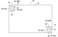
- FIG. 17 is a schematic diagram showing an example of the arrangement of two mounting members 40 on a workbench 30.
- the two mounting members 40 are arranged, for example, at two diagonally opposite corners of the mounting surface 35.
- Each mounting member 40 is arranged, for example, so that the longitudinal direction of the groove portion 41 is parallel to the short direction of the mounting surface 35.
- the two mounting members 40 are arranged so that the depth direction of one mounting member 40 (i.e., the direction from the opening 45 toward the wall surface 44) and the depth direction of the other mounting member 40 are in the same direction.
- the mounting member 40 at the bottom right of FIG. 17 may be referred to as the first mounting member 40A
- the mounting member 40 at the top left of FIG. 17 may be referred to as the second mounting member 40B.
- the identification unit 25 identifies the posture of the mounting surface 35 based on the reference second contact position information and the acquired second contact position information for the first mounting member 40A and the reference second contact position information and the acquired second contact position information for the second mounting member 40B.
- the reference first contact position information and the acquired first contact position information for the first mounting member 40A and the reference first contact position information and the acquired first contact position information for the second mounting member 40B are not used.
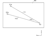
- FIG. 18 is a schematic diagram showing an example of the reference second contact position coordinate P11 and the acquired second contact position coordinate P21 for the first mounting member 40A, and the reference second contact position coordinate P12 and the acquired second contact position coordinate P22 for the second mounting member 40B.
- the mounting surface 35 and the reference mounting member 40 in the reference position and orientation are shown with dashed lines.
- the target worktable 30 and the target mounting member 40 are shown with solid lines.
- the identification unit 25 sets one of the first mounting member 40A and the second mounting member 40B as the reference mounting member 40 in a calibration using two mounting members 40 (also called a two-use calibration).
- This reference mounting member 40 can also be called the main mounting member 40.
- the reference mounting member 40 in a two-use calibration will be called the main mounting member 40.
- a mounting member 40 different from the main mounting member 40 may be called the secondary mounting member 40.
- a calibration using one mounting member 40 may be called a single-use calibration.
- the identification unit 25 first obtains a vector V11 from the reference second contact position coordinate of the main placement member 40 to the reference second contact position coordinate of the sub placement member 40.
- the identification unit 25 also obtains a vector V12 from the acquired second contact position coordinate of the main placement member 40 to the acquired second contact position coordinate of the sub placement member 40.
- the upper part of FIG. 19 shows vectors V11 and V12 when the main placement member 40 is the first placement member 40A.
- the vector V11 extends from the reference second contact position coordinate P11 of the first placement member 40A to the reference second contact position coordinate P12 of the second placement member 40B.
- the vector V12 extends from the acquired second contact position coordinate P21 of the first placement member 40A to the acquired second contact position coordinate P22 of the second placement member 40B.
- the vectors V11 and V12 are three-dimensional vectors.
- the identification unit 25 aligns the starting point of vector V11 with the starting point of vector V12.
- the lower part of Figure 19 shows the state in which the starting point of vector V11 is aligned with the starting point of vector V12 when the main mounting member 40 is the first mounting member 40A.
- the position coordinates of the end point of vector V11 after the starting point of vector V11 is aligned with the starting point of vector V12 are indicated by P12a.
- the identification unit 25 determines the angle ⁇ 2 formed by vector V11 and vector V12.
- the identification unit 25 obtains a second rotation matrix for rotating the vector V11 by an angle ⁇ 2 around the starting point of the vector V12 (the acquired second contact position coordinate P21 in FIG. 19) and overlapping it with the vector V12.
- the second rotation matrix represents the three-dimensional orientation of the target placement surface 35, similar to the first rotation matrix described above.
- the identification unit 25 obtains the second rotation matrix based on the reference second contact position coordinate P11, the reference second contact position coordinate P12, the acquired second contact position coordinate P21, and the acquired second contact position coordinate P22, thereby identifying the three-dimensional orientation of the target placement surface 35.
- the robot control unit 20 corrects the reference working point coordinate I11 based on the second rotation matrix and the acquired second contact position information of the main mounting member 40 to obtain the target working point coordinate I12. Specifically, for example, when the first mounting member 40A is the main mounting member 40, the robot control unit 20 obtains an X-coordinate offset value obtained by subtracting the X-coordinate value of the reference second contact position coordinate P11 of the first mounting member 40A from the X-coordinate value of the acquired second contact position coordinate P21 of the first mounting member 40A.
- the robot control unit 20 also obtains a Y-coordinate offset value obtained by subtracting the Y-coordinate value of the reference second contact position coordinate P11 from the Y-coordinate value of the acquired second contact position coordinate P21.
- the robot control unit 20 then obtains a Z coordinate offset value by subtracting the Z coordinate value of the reference second contact position coordinate P11 from the Z coordinate value of the acquired second contact position coordinate P21.
- the robot control unit 20 determines the position coordinates obtained by adding the X coordinate offset value, the Y coordinate offset value, and the Z coordinate offset value to the X coordinate value, the Y coordinate offset value, and the Z coordinate offset value of the reference working point coordinate I11, respectively, as the offset position coordinates.
- the robot control unit 20 then multiplies the offset position coordinates obtained by offsetting the reference working point coordinate I11 by the second rotation matrix as the target working point coordinate I12.
- the second contact position information for one of the mounting members 40 is acquired, and then the second contact position information for the other mounting member 40 is acquired.
- the operator grasps and moves the end effector 15 of the robot 10 in free drive mode so that the tip 65 contacts only one of the opposing surfaces 43 of the inner surface 42 of the groove portion 41 of one of the mounting members 40 on the target worktable 30, or places the tip 65 close to one of the opposing surfaces 43.
- the processing device 1 then executes steps s1 to s11 shown in FIG. 13 in response to the operator's instructions to acquire the second contact position information for one of the mounting members 40.
- the processing device 1 executes steps s1 to s10 shown in FIG. 13 in response to the instructions of the worker to acquire second contact position information for the other mounting member 40. Then, the processing device 1 specifies the posture of the target mounting surface 35 based on the reference second contact position information and the acquired second contact position information for one mounting member 40 and the reference second contact position information and the acquired second contact position information for the other mounting member 40, as described above. Then, the processing device 1 corrects the reference working point position information based on the specified posture of the target mounting surface 35 and the acquired second contact position information of the main mounting member 40 of the two mounting members 40, to acquire the target working point position information.
- the robot control unit 20 may acquire the height information of the placement surface 35 based on the acquired second contact position information.
- the robot control unit 20 may acquire the height information of the placement surface 35 based on the acquired second contact position information and placement member shape information representing the shape of the placement member.
- the robot control unit 20 can also acquire the height information of the placement surface 35 based on a distance image obtained by the camera 9.
- the accuracy of the height information of the placement surface 35 acquired based on the distance image may be lower than the accuracy of the height information of the placement surface 35 calculated based on the acquired second contact position information.
- the robot control unit 20 may control the robot 10 based on the position information of the placement surface 35 calculated based on the acquired second contact position information.
- the posture of the mounting surface 35 is identified based on the opposing member information regarding the opposing member 60 acquired when the opposing member 60 is in contact with at least one mounting member 40 arranged on the mounting surface 35. Then, the movement of the robot 10 is controlled based on the identified posture of the mounting surface 35. This allows the robot 10 to perform movements according to the posture of the mounting surface 35, and the movement of the robot 10 is appropriately controlled.
- the robot control unit 20 may acquire position information of the placement surface 35 when controlling the robot 10. In other words, when the positional relationship between the placement member 40 and the working point 200 is fixed, the robot 10 may be moved to the working point 200 based on the position where the opposing member 60 of the robot 10 makes three-point contact with the placement member 40.
- the mounting member 40 on the mounting surface 35 of the target object 50 becomes large, there is a possibility that the mounting member 40 may interfere with the work of the robot 10, so it is difficult to make the mounting member 40 large. Therefore, in one-piece calibration, it is difficult to increase the lengths of the vectors V1 and V2 (see FIG. 16). Therefore, if an error is included in the acquired first contact position coordinate A2 and the acquired second contact position coordinate P2, when the start point of the vector V1 is made to coincide with the start point of the vector V2, the angle ⁇ 1 does not appear properly, and the first rotation matrix representing the attitude of the mounting surface 35 may not be obtained properly.
- the arrangement of the two mounting members 40 is not limited to the example in FIG. 17.
- the two mounting members 40 may be arranged side by side along the longitudinal direction of the mounting surface 35, or side by side along the lateral direction of the mounting surface 35.
- each of the pair of opposing surfaces 43 of the groove portion 41 of the mounting member 40 is inclined outwardly toward the upper side, but only one of the pair of opposing surfaces 43 may be inclined outwardly toward the upper side.
- FIG. 20 is a schematic diagram showing an example in which only the first opposing surface 43a of the pair of opposing surfaces 43 is inclined outwardly toward the upper side. When only one of the pair of opposing surfaces 43 is inclined, the tip 65 of the opposing member 60 may come into contact with the inclined opposing surface 43 at one point during calibration.
- FIG. 21 is a schematic diagram showing an example of a mounting member 40 (also called mounting member 40D) used in this case.
- a mark 500 is provided on the upper surface 40a of the mounting member 40D to identify the position and posture of the mounting member 40D.
- the robot control unit 20 acquires a color image obtained by the camera 90 through the interface 4.
- the robot control unit 20 identifies the position and posture of the mounting member 40D based on the mark 500 appearing in the acquired color image.
- the robot control unit 20 identifies the position and posture of the first opposing surface 43a based on the identified position and posture of the mounting member 40D and mounting member shape information representing the shape of the mounting member 40D.
- the mounting member shape information is stored in the memory unit 3.
- the robot control unit 20 controls the movement of the robot 10 based on the identified position and posture of the first opposing surface 43a to bring the tip 65 of the opposing member 60 into contact with only the first opposing surface 43a or to position the tip 65 near the first opposing surface 43a. Then, for example, the process shown in FIG. 13 above is executed to adjust the movement of the robot 10 relative to the target placement surface 35.
- the mark 500 on the mounting member 40 may be used to calibrate the camera 9.
- Calibration of the camera 9 is a process of converting each position in the camera coordinate system, which is a three-dimensional coordinate system set in the camera 9, into a position in the robot coordinate system 100, which is the basis for control of the robot 10.
- the camera coordinate system may be calibrated based on the robot coordinates when the opposing member 60 of the robot 10 is in three-point contact with the groove portion 41.
- the position of the target object 50 may be recognized by the camera 9, and the robot 10 may be moved to the working position based on the recognition by the camera 9.
- the tip 65 is specified to be in one-point contact with the inner surface 42 of the groove 41, but the one-point contact need not be specified.
- the tip 65 when calibration is started, the tip 65 is placed at the bottom of the inner surface 42 of the groove 41 and in two-point contact with the inner surface 42 by the operator or by the control of the robot 10 by the robot control unit 20, or is placed near the bottom.
- the robot control unit 20 specifies whether the tip 65 is in two-point contact with the inner surface 42 of the groove 41 based on the force detection information output by the sensor 18.
- the robot control unit 20 moves the tip 65 downward on the mounting member 40 while checking the force detection information, and makes the tip 65 in two-point contact with the inner surface 42 of the groove 41. Thereafter, the processing device 1 operates in the same manner.
- the placement member 40 is used to determine the posture of the placement surface, but the placement member 40 may be used to set or calibrate the robot control point or tool center point.
- the robot control point or tool center point may be set based on the position where the tip 65 of the opposing member 60 makes three-point contact with the placement member 40.
- the posture of the arm is changed while correcting the control value of the arm to maintain the three-point contact, thereby calibrating the robot control point or tool center point.
- the robot control point or tool center point is a point that is treated as a reference point for control when the robot is operated, and is set to the point where the object 50 is located when the robot 10 grasps the object 50, for example.
- the shape of the tip 65 is not limited to the above example.
- the tip 65 may be a polyhedron.
- FIG. 22 is a schematic diagram showing an example of a polyhedron tip 65.
- the shape of the tip 65 (also called tip 65A) shown in FIG. 22 is a polygonal prism.
- the shape of the tip 65A is a low triangular prism.
- the triangular prism that constitutes the tip 65A has a shape that corresponds to the shape of the inner surface 42 of the groove 41 of the mounting member 40, and can enter the inside of the groove 41.
- the tip 65A can move within the groove 41 along the longitudinal direction of the groove 41.
- the triangular prism formed by the tip 65A has three side surfaces 65a, 65b, and 66c, and a pair of bottom surfaces 65d.
- One end of the rod-shaped portion 61 of the opposing member 60 is connected to the side surface 65a.
- the side surfaces 65b and 65c each come into contact with the pair of opposing surfaces 43 of the groove 41.
- each of the side surfaces 65b and 65c is in surface contact with the opposing surface 43.
- Figure 22 shows an example of the state in which the side surfaces 65b and 65c each come into contact with the pair of opposing surfaces 43 of the groove 41.
- the tip 65A moves inside the groove 41 and reaches the wall surface 44 of the groove 41, one of the pair of bottom surfaces 65d comes into contact with the wall surface 44. At this time, the bottom surface 65d comes into surface contact with the wall surface 44.
- the operator grasps and moves the end effector 15 in his/her hand so that the side surfaces 65b and 65c of the tip 65A come into contact with the pair of facing surfaces 43 of the groove 41, respectively, or the side surfaces 65b and 65c are positioned near the pair of facing surfaces 43.
- the robot control unit 20 controls the movement of the robot 10 so that the side surfaces 65b and 65c of the tip 65A come into contact with the pair of facing surfaces 43 of the groove 41, respectively, or the side surfaces 65b and 65c are positioned near the pair of facing surfaces 43.
- the robot control unit 20 determines whether the side surfaces 65b and 65c of the tip 65A are in contact with the pair of opposing surfaces 43 of the groove 41 based on the force detection information output by the sensor 18. If the side surfaces 65b and 65c of the tip 65A are not in contact with the pair of opposing surfaces 43 of the groove 41, the robot control unit 20 moves the tip 65A downward on the mounting member 40 while checking the force detection information, so that the side surfaces 65b and 65c come into contact with the pair of opposing surfaces 43.
- the robot control unit 20 acquires the position information of the tip 65A at that time as first contact position information. After that, while checking the force detection information, the robot control unit 20 moves the tip 65A to the wall surface 44 of the groove portion 41 and brings one bottom surface 65d of the tip 65A into contact with the wall surface 44. As a result, the side surfaces 65b and 65c of the tip 65A are in contact with the pair of opposing surfaces 43, and one bottom surface 65d of the tip 65A is in contact with the wall surface 44.
- the robot control unit 20 acquires the position information of the tip 65A at that time as second contact position information.
- the robot control unit 20 determines the posture of the target placement surface 35 based on the acquired first contact position information and second contact position information in the same manner as described above. The robot control unit 20 then corrects the reference working point position information based on the determined posture of the target placement surface 35 and the acquired second contact position information to obtain the target working point position information.
- the robot control unit 20 similarly identifies the posture of the target mounting surface 35 based on the second contact position information of one mounting member 40 acquired by using the tip portion 65A as described above, and the second contact position information of the other mounting member 40 acquired by using the tip portion 65A. Then, the robot control unit 20 corrects the reference working point position information based on the identified posture of the target mounting surface 35 and the second contact position information to obtain the target working point position information.
- the robot control unit 20 does not need to acquire the first contact position information.
- the robot control unit 20 may acquire the reference work point coordinates and use the above offset position coordinates, which are offset based on the second contact position information, as the target work point coordinates. In this way, if the position of the worktable 30 deviates from the reference position but the attitude of the worktable 30 hardly deviates from the reference attitude, the robot control unit 20 can also control the movement of the robot 10 based on the position information of the opposing member 60 at a specified contact position of the mounting member 40.
- the robot control unit 20 may set the position coordinates obtained by multiplying the reference workpoint coordinates by the first rotation matrix or the second rotation matrix as the target workpoint coordinates.
- the recess 41 (also called recess 41F) of the mounting member 40 (also called mounting member 40F) shown in Figures 23 and 24 is open not only to the top surface 40a but also to the bottom surface 40b of the mounting member 40F.
- the inner surface 42 (also called inner surface 42F) of the recess 41F is, for example, a truncated cone shape whose diameter decreases from the top surface 40a toward the bottom surface 40b.
- Figure 24 shows the cross-sectional shape of the mounting member 40 along the depth direction of the recess 41F.
- a rounded tip 65 of a sphere or hemisphere is inserted into the recess 41F.
- the tip 65 makes line contact with the inner surface 42F of the recess 41F.
- Figure 24 shows an example of how the tip 65 makes line contact with the inner surface 42F of the recess 41F.
- the operator grasps and moves the end effector 15 in his/her hand so that the tip 65 touches the inner surface 42F of the recess 41F or is positioned close to the inner surface 42F.
- the robot control unit 20 controls the movement of the robot 10 so that the tip 65 touches the inner surface 42F of the recess 41F or is positioned close to the inner surface 42F.
- the robot control unit 20 determines whether the tip 65 is in line contact with the inner surface 42F of the recess 41F based on the force detection information. If the tip 65 is not in line contact with the inner surface 42F, the robot control unit 20 moves the tip 65 while checking the force detection information, and brings the tip 65 into line contact with the inner surface 42F. If the tip 65 is in line contact with the inner surface 42F, the robot control unit 20 acquires position information of the tip 62 at that time as third contact position information. The robot control unit 20 uses the acquired third contact position information instead of the second contact position information to determine offset position coordinates obtained by offsetting the reference working point coordinates. The robot control unit 20 then sets the acquired offset position coordinates as the target working point coordinates.
- FIGs 25 and 26 are schematic diagrams showing another example of a mounting member 40 used when the position of the work table 30 deviates from the reference position, but the posture of the work table 30 hardly deviates from the reference posture.
- the tip portion 65 also called tip portion 65H
- Tip portion 65H fits inside the recess 41 (also called recess 41H) of the mounting member 40H.
- Figure 26 shows tip portion 65H fitting inside recess 41H.
- the tip 65H is shaped like a low triangular prism.
- the triangular prism that the tip 65H forms has three side surfaces 65p and a pair of bottom surfaces 65q and 65r.
- One end of the rod-shaped portion 61 of the opposing member 60 is connected to one bottom surface 65q.
- the operator grasps and moves the end effector 15 to bring the bottom surface 65r and two side surfaces 65p of the tip portion 65H into contact with the bottom surface 42a and two side surfaces 42b of the recess 41H, respectively.
- the operator positions the bottom surface 65r and two side surfaces 65p of the tip portion 65H near the bottom surface 42a and two side surfaces 42b of the recess 41H, respectively.
- the robot control unit 20 controls the movement of the robot 10 so that the bottom surface 65r and two side surfaces 65p of the tip portion 65H come into contact with the bottom surface 42a and two side surfaces 42b of the recess 41H, respectively.
- the robot control unit 20 controls the movement of the robot 10 so that the bottom surface 65r and the two side surfaces 65p of the tip 65H are positioned near the bottom surface 42a and the two side surfaces 42b of the recess 41H, respectively.
- the robot control unit 20 determines whether the bottom surface 65r and two side surfaces 65p of the tip portion 65H are in contact with the bottom surface 42a and two side surfaces 42b of the recessed portion 41H. If the bottom surface 65r and two side surfaces 65p of the tip portion 65H are not in contact with the bottom surface 42a and two side surfaces 42b of the recessed portion 41H, the robot control unit 20 moves the tip portion 65H while checking the force detection information, and brings the bottom surface 65r and two side surfaces 65p of the tip portion 65H into contact with the bottom surface 42a and two side surfaces 42b of the recessed portion 41H, respectively.
- the robot control unit 20 acquires the position information of the tip portion 65 at that time as the fourth contact position information.
- the robot control unit 20 uses the acquired fourth contact position information instead of the second contact position information to determine the offset position coordinates by offsetting the reference working point coordinates.
- the robot control unit 20 sets the determined offset position coordinates as the target working point coordinates.
- the determination unit 25 can also determine the posture of the support surface 35 based on information about the tip 65H when the tip 65H fits inside the recess 41H and contacts the inner surface 42H. Information about the tip 65H when the tip 65H fits inside the recess 41H and contacts the inner surface 42H can also be said to be contact opposing member information. A method for determining the posture of the support surface 35 in this case will be described below.
- a first fixed point and a second fixed point are set for one of the bottom surfaces 65q and 65r. Since the bottom surfaces 65q and 65r are parallel to the mounting surface 35, the line connecting the first fixed point and the second fixed point is parallel to the target mounting surface 35, similar to the line connecting the first contact position and the second contact position described above.
- the position coordinates of the first fixed point and the position coordinates of the second fixed point when the tip portion 65H is fitted into the recess 41H of the mounting member 40H on the mounting surface 35 in the reference position and posture are stored in the memory unit 3 as the reference first fixed point coordinates and the reference second fixed point coordinates, respectively.
- the first fixed point may be set at the apex of the triangular bottom surface 65q or 65r.
- the second fixed point may be set at the center of the bottom surface 65q or 65r, or at the intersection of the tip portion 65H and the rod-shaped portion 61.
- the identification unit 25 acquires the position coordinates of the first fixed point and the position coordinates of the second fixed point when the tip 65H is engaged with the recess 41H of the target mounting member 40H on the target mounting surface 35.
- the acquired position coordinates of the first fixed point and the position coordinates of the second fixed point are referred to as the acquired first fixed point coordinates and the acquired second fixed point coordinates, respectively.
- the acquired first fixed point coordinates and the acquired second fixed point coordinates can be said to be information about the tip 65H when the tip 65H is engaged inside the recess 41H and in contact with the inner surface 42H, and can also be said to be contact opposing member information.
- the identification unit 25 uses the reference first fixed point coordinates, the reference second fixed point coordinates, the acquired first fixed point coordinates, and the acquired second fixed point coordinates, respectively, instead of the reference first contact position coordinates, the reference second contact position coordinates, the acquired first contact position coordinates, and the acquired second contact position coordinates, to identify the orientation of the target placement surface 35. Specifically, the identification unit 25 obtains a first vector (corresponding to vector V1) from the reference second fixed point coordinates to the reference first fixed point coordinates, and a second vector (corresponding to vector V2) from the acquired second fixed point coordinates to the acquired first fixed point coordinates. Next, the identification unit 25 matches the starting point of the first vector with the starting point of the second vector, and then obtains the angle formed by the first vector and the second vector.
- the identification unit 25 obtains a third rotation matrix for rotating the first vector by the obtained angle around the starting point of the second vector to overlap it with the second vector.
- the third rotation matrix represents the three-dimensional position and orientation of the target placement surface 35. It can also be said that the determination unit 25 determines the three-dimensional orientation of the target placement member 40 by determining a third rotation matrix based on the reference first fixed point coordinates, the reference second fixed point coordinates, the acquired first fixed point coordinates, and the acquired second fixed point coordinates.
- the robot control unit 20 determines offset position coordinates obtained by offsetting the reference working point coordinates using the acquired second fixed point coordinates and the reference second fixed point coordinates instead of the acquired second contact position coordinates and the reference second contact position coordinates. The robot control unit 20 then multiplies the offset position coordinates by the third rotation matrix to obtain the target working point coordinates.
- the identification unit 25 identifies the three-dimensional orientation of the target placement surface 35, but the identification unit 25 may identify at least the orientation of the target placement surface 35 as viewed from above. For example, consider a case where the orientation of the target placement surface 35 as viewed from above is identified in single-use calibration. In this case, the identification unit 25 matches the start point of the vector V1 with the start point of the vector V2, as in the lower part of FIG. 16 described above. Next, as shown in FIG.
- the identification unit 25 considers a specific plane 900 that includes the position coordinate A1a of the end point of the vector V1 after matching the start point of the vector V1 with the start point of the vector V2 and the acquired second contact position coordinate P2, and is parallel to the XY plane of the robot coordinate system 100.
- the specific plane 900 is treated as a plane formed by the XY components of the reference placement surface 35, for example.
- the specific plane 900 may be treated as a plane onto which the reference placement surface 35 is projected, for example, as a plane perpendicular to the Z axis or weight direction.
- the identification unit 25 obtains a position coordinate A2x obtained by projecting the acquired first contact position coordinate A2 of the vector V2 onto the specific surface 900.
- the position coordinate A2x is the position coordinate of the foot of a perpendicular line drawn from the acquired first contact position coordinate A2 onto the specific surface 900.
- the vector from the acquired second contact position coordinate P2 to the position coordinate A2x is called vector V2x. It can be said that the vector V2x is the vector obtained by projecting the vector V2 onto the specific surface 900.
- the identification unit 25 obtains a fourth rotation matrix for rotating the vector V1 by an angle ⁇ 11 around the acquired second contact position coordinate P2 to overlap with the vector V2x.
- the fourth rotation matrix represents the orientation of the target placement surface 35 as viewed from above.
- the fourth rotation matrix represents the orientation of the target placement surface 35 when viewed from the positive side of the Z axis of the robot coordinate system 100.
- the fourth rotation matrix represents the relative orientation of the target placement surface 35 with respect to the reference placement surface 35 when viewed from above.
- the identification unit 25 determines the orientation of the target placement surface 35 as viewed from above by obtaining the fourth rotation matrix.
- the fourth rotation matrix represents the rotation within the plane of the identification surface 900. It can also be said that the identification unit 25 determines the rotation from the reference orientation of the target placement surface 35 when viewed from above by obtaining the fourth rotation matrix.
- the robot control unit 20 determines, for example, offset position coordinates obtained by offsetting the reference working point coordinates I1 in the same manner as described above. The robot control unit 20 then multiplies the offset position coordinates by the fourth rotation matrix to obtain the position coordinates as the target working point coordinates I2.
- the target work point position information can be obtained with a certain degree of accuracy.
- the identification unit 25 can similarly identify the posture of the target placement surface 35 as viewed from above.
- the identification unit 25 matches the starting point of the vector V11 with the starting point of the vector V12, as in the lower part of FIG. 19 described above.
- the identification unit 25 considers a specific surface 950 that includes the position coordinate P12a of the end point of the vector V11 after matching the starting point of the vector V11 with the starting point of the vector V12 and the acquired second contact position coordinate P21, and is parallel to the XY plane of the robot coordinate system 100.
- the identification unit 25 obtains a position coordinate P22x obtained by projecting the acquired second contact position coordinate P22 of the vector V12 onto the specific surface 950.
- the position coordinate P22x is the position coordinate of the foot of a perpendicular line drawn from the acquired second contact position coordinate P22 to the specific surface 950.
- the vector from the acquired second contact position coordinate P21 to the position coordinate P22x is called a vector V12x.
- specific surface 950 is, for example, similar to specific surface 900.
- the identification unit 25 obtains a fifth rotation matrix for rotating the vector V11 by an angle ⁇ 22 around the acquired second contact position coordinate P21 to overlap with the vector V12x.
- the fifth rotation matrix like the fourth rotation matrix, represents the orientation of the target placement surface 35 as viewed from above.
- the fifth rotation matrix represents the orientation of the target placement surface 35 when viewed from the positive side of the Z axis of the robot coordinate system 100.
- the robot control unit 20 determines the offset position coordinates by offsetting the reference working point coordinates I11 in the same manner as described above. The robot control unit 20 then multiplies the offset position coordinates by the fifth rotation matrix to obtain the position coordinates as the target working point coordinates I12.
- This disclosure includes the following:
- the processing device includes an acquisition unit that acquires opposing member information when at least one mounting member is placed on a work object mounting surface of an unfixed work table for a robot and an opposing member of the robot is in contact with the at least one mounting member, an identification unit that identifies the orientation of the mounting surface as viewed from above or the three-dimensional orientation of the mounting surface based on the opposing member information, and a robot control unit that controls the movement of the robot based on the orientation identified by the identification unit.
- the at least one mounting member has a first mounting member
- the opposing member information includes first position information of the opposing member at a first contact position of the first mounting member and second position information of the opposing member at a second contact position on the first mounting member that is spaced along the mounting surface from the first contact position
- the identification unit identifies the posture based on the first position information and the second position information.
- the first mounting member has a groove portion extending parallel to the mounting surface, the first contact position is located on the inner surface of the groove portion, and the second contact position is located on the inner surface of the groove portion away from the first contact position along the longitudinal direction of the groove portion.
- the inner surface of the groove portion includes a wall surface located at one end of the groove portion in the longitudinal direction, and the second contact position is the contact position of the opposing member with the wall surface.
- the at least one mounting member has a first mounting member
- the opposing member information includes position information of the opposing member at a predetermined contact position of the first mounting member
- the robot control unit controls the movement of the robot based on the position information.
- the first mounting member has a groove portion having a wall surface that extends parallel to the mounting surface and is located at one end in the longitudinal direction, and the predetermined contact position is a position where the opposing member contacts the wall surface.
- the at least one mounting member has a first mounting member and a second mounting member positioned away from the first mounting member
- the opposing member information includes first position information of the opposing member at a first contact position of the first mounting member and second position information of the opposing member at a second contact position of the second mounting member
- the identification unit identifies the posture based on the first position information and the second position information.
- the mounting member is a mounting member that is placed on the mounting surface of the robot for the work object, and has a groove portion into which the tip of the member placed on the robot fits, and the inner surface of the groove portion has multiple surfaces that each make point contact with the tip.
- the multiple surfaces have multiple opposing surfaces that face each other, and the multiple opposing surfaces include inclined surfaces that slope outwardly in an upward direction.
- the multiple surfaces have a wall surface located at one end of the groove in the longitudinal direction.
- the processing device includes a robot control unit that controls the robot so that the tip of the member moves within the groove of the mounting member of (10) or (11) above, and the robot control unit determines the contact state of the tip with the inner surface of the groove based on the detection result of a sensor that detects the force applied to the tip, and controls the robot so that the tip moves within the groove to the wall surface based on the determined contact state.
- the robot control unit controls the robot so that when the tip portion makes contact with the inner surface at two points, the tip portion moves toward the wall surface of the inner surface of the groove portion, and when the tip portion makes contact with the inner surface at three points, the robot is caused to stop moving the tip portion.
- the robot control unit controls the robot so that when the tip portion comes into contact with the inner surface at one point, the tip portion moves toward the bottom of the inner surface of the groove portion.
- the program is a program for causing a computer device to function as any one of the processing devices (1) to (7) and (12) to (14) above.
Landscapes
- Engineering & Computer Science (AREA)
- Robotics (AREA)
- Mechanical Engineering (AREA)
- Human Computer Interaction (AREA)
- Manipulator (AREA)
Priority Applications (1)
| Application Number | Priority Date | Filing Date | Title |
|---|---|---|---|
| JP2025507158A JPWO2024190883A1 (2) | 2023-03-15 | 2024-03-14 |
Applications Claiming Priority (2)
| Application Number | Priority Date | Filing Date | Title |
|---|---|---|---|
| JP2023040659 | 2023-03-15 | ||
| JP2023-040659 | 2023-03-15 |
Publications (1)
| Publication Number | Publication Date |
|---|---|
| WO2024190883A1 true WO2024190883A1 (ja) | 2024-09-19 |
Family
ID=92755310
Family Applications (1)
| Application Number | Title | Priority Date | Filing Date |
|---|---|---|---|
| PCT/JP2024/010085 Ceased WO2024190883A1 (ja) | 2023-03-15 | 2024-03-14 | 処理装置、載置部材及びプログラム |
Country Status (2)
| Country | Link |
|---|---|
| JP (1) | JPWO2024190883A1 (2) |
| WO (1) | WO2024190883A1 (2) |
Citations (9)
| Publication number | Priority date | Publication date | Assignee | Title |
|---|---|---|---|---|
| US5329092A (en) * | 1991-11-27 | 1994-07-12 | Deere & Company | Welding torch alignment monitor |
| WO1998032571A1 (en) * | 1997-01-29 | 1998-07-30 | Kabushiki Kaisha Yaskawa Denki | Device and method for calibrating robot |
| JP2001038662A (ja) * | 1999-08-04 | 2001-02-13 | Honda Motor Co Ltd | 作業ロボットの校正方法 |
| JP2006297559A (ja) * | 2005-04-22 | 2006-11-02 | Yaskawa Electric Corp | キャリブレーションシステムおよびロボットのキャリブレーション方法 |
| JP2011011326A (ja) * | 2009-07-06 | 2011-01-20 | Ihi Corp | ロボットのツール位置較正治具と方法 |
| US20110046782A1 (en) * | 2008-04-30 | 2011-02-24 | Abb Technology Ab | A method and system for determining the relation between a robot coordinate system and a local coordinate system located in the working range of the robot |
| JP2011067889A (ja) * | 2009-09-25 | 2011-04-07 | Ihi Corp | キャリブレーション装置及びキャリブレーション方法 |
| JP2019042837A (ja) * | 2017-08-31 | 2019-03-22 | セイコーエプソン株式会社 | ロボット、ロボット制御装置、ロボットシステム、及びロボット制御方法 |
| CN115338870A (zh) * | 2022-09-14 | 2022-11-15 | 苏州瀚华智造智能技术有限公司 | 一种面向简单几何特征的机器人装夹标定方法 |
-
2024
- 2024-03-14 JP JP2025507158A patent/JPWO2024190883A1/ja active Pending
- 2024-03-14 WO PCT/JP2024/010085 patent/WO2024190883A1/ja not_active Ceased
Patent Citations (9)
| Publication number | Priority date | Publication date | Assignee | Title |
|---|---|---|---|---|
| US5329092A (en) * | 1991-11-27 | 1994-07-12 | Deere & Company | Welding torch alignment monitor |
| WO1998032571A1 (en) * | 1997-01-29 | 1998-07-30 | Kabushiki Kaisha Yaskawa Denki | Device and method for calibrating robot |
| JP2001038662A (ja) * | 1999-08-04 | 2001-02-13 | Honda Motor Co Ltd | 作業ロボットの校正方法 |
| JP2006297559A (ja) * | 2005-04-22 | 2006-11-02 | Yaskawa Electric Corp | キャリブレーションシステムおよびロボットのキャリブレーション方法 |
| US20110046782A1 (en) * | 2008-04-30 | 2011-02-24 | Abb Technology Ab | A method and system for determining the relation between a robot coordinate system and a local coordinate system located in the working range of the robot |
| JP2011011326A (ja) * | 2009-07-06 | 2011-01-20 | Ihi Corp | ロボットのツール位置較正治具と方法 |
| JP2011067889A (ja) * | 2009-09-25 | 2011-04-07 | Ihi Corp | キャリブレーション装置及びキャリブレーション方法 |
| JP2019042837A (ja) * | 2017-08-31 | 2019-03-22 | セイコーエプソン株式会社 | ロボット、ロボット制御装置、ロボットシステム、及びロボット制御方法 |
| CN115338870A (zh) * | 2022-09-14 | 2022-11-15 | 苏州瀚华智造智能技术有限公司 | 一种面向简单几何特征的机器人装夹标定方法 |
Also Published As
| Publication number | Publication date |
|---|---|
| JPWO2024190883A1 (2) | 2024-09-19 |
Similar Documents
| Publication | Publication Date | Title |
|---|---|---|
| US11254008B2 (en) | Method and device of controlling robot system | |
| JP6966582B2 (ja) | ロボットモーション用のビジョンシステムの自動ハンドアイ校正のためのシステム及び方法 | |
| CN108453701B (zh) | 控制机器人的方法、示教机器人的方法和机器人系统 | |
| US9517563B2 (en) | Robot system using visual feedback | |
| CN107428009B (zh) | 用于工业机器人调试的方法、使用该方法的工业机器人系统和控制系统 | |
| US10434655B2 (en) | Robot apparatus and method for controlling robot apparatus | |
| US9519736B2 (en) | Data generation device for vision sensor and detection simulation system | |
| US12290945B2 (en) | Robot device controller for controlling position of robot | |
| US20240139935A1 (en) | Robotic arm calibration method | |
| CN106003021A (zh) | 机器人、机器人控制装置以及机器人系统 | |
| JP4794011B2 (ja) | 画像処理装置、およびロボット制御システム | |
| JP6885856B2 (ja) | ロボットシステムおよびキャリブレーション方法 | |
| JP2020138292A (ja) | ロボットシステムおよび制御方法 | |
| JP2020138293A (ja) | ロボットシステムおよび制御方法 | |
| JP2021024075A (ja) | ロボットの位置を制御するロボット装置の制御装置 | |
| WO2024190883A1 (ja) | 処理装置、載置部材及びプログラム | |
| US20240246237A1 (en) | Robot control device, robot control system, and robot control method | |
| JP7583942B2 (ja) | ロボット制御装置、ロボット制御システム、及びロボット制御方法 | |
| JP2016203282A (ja) | エンドエフェクタの姿勢変更機構を備えたロボット | |
| CN118510633A (zh) | 具备三维传感器的机器人装置以及机器人装置的控制方法 | |
| US20250001594A1 (en) | Robot control device, robot control system, and robot control method | |
| JP2022164308A (ja) | システム、製造方法、制御方法、プログラム、媒体 | |
| JP2024101194A (ja) | ロボット制御装置及び搬送ロボットシステム | |
| WO2022202655A1 (ja) | 3次元測定システム |
Legal Events
| Date | Code | Title | Description |
|---|---|---|---|
| 121 | Ep: the epo has been informed by wipo that ep was designated in this application |
Ref document number: 24770986 Country of ref document: EP Kind code of ref document: A1 |
|
| ENP | Entry into the national phase |
Ref document number: 2025507158 Country of ref document: JP Kind code of ref document: A |
|
| WWE | Wipo information: entry into national phase |
Ref document number: 2025507158 Country of ref document: JP |
|
| NENP | Non-entry into the national phase |
Ref country code: DE |
|
| 122 | Ep: pct application non-entry in european phase |
Ref document number: 24770986 Country of ref document: EP Kind code of ref document: A1 |